

Page 1
Cartridge Seals
Installation
Instructions
Experience In Motion
Page 2
1 Equipment Check
1.1 Follow plant safety regulations prior to equipment disassembly:
• lock out motor and valves.
• wear designated personal safety equipment.
• relieve any pressure in the system.
• consult plant MSDS les for hazardous material regulations.
1.2 Disassemble equipment to allow access to seal installation area.
1.3 Remove all burrs and sharp edges from the shaft or sleeve
including sharp edges of keyways and threads. Replace shaft or
sleeve if it is worn in the sleeve gasket area. Make sure the seal
housing bore and face are clean and free of burrs.
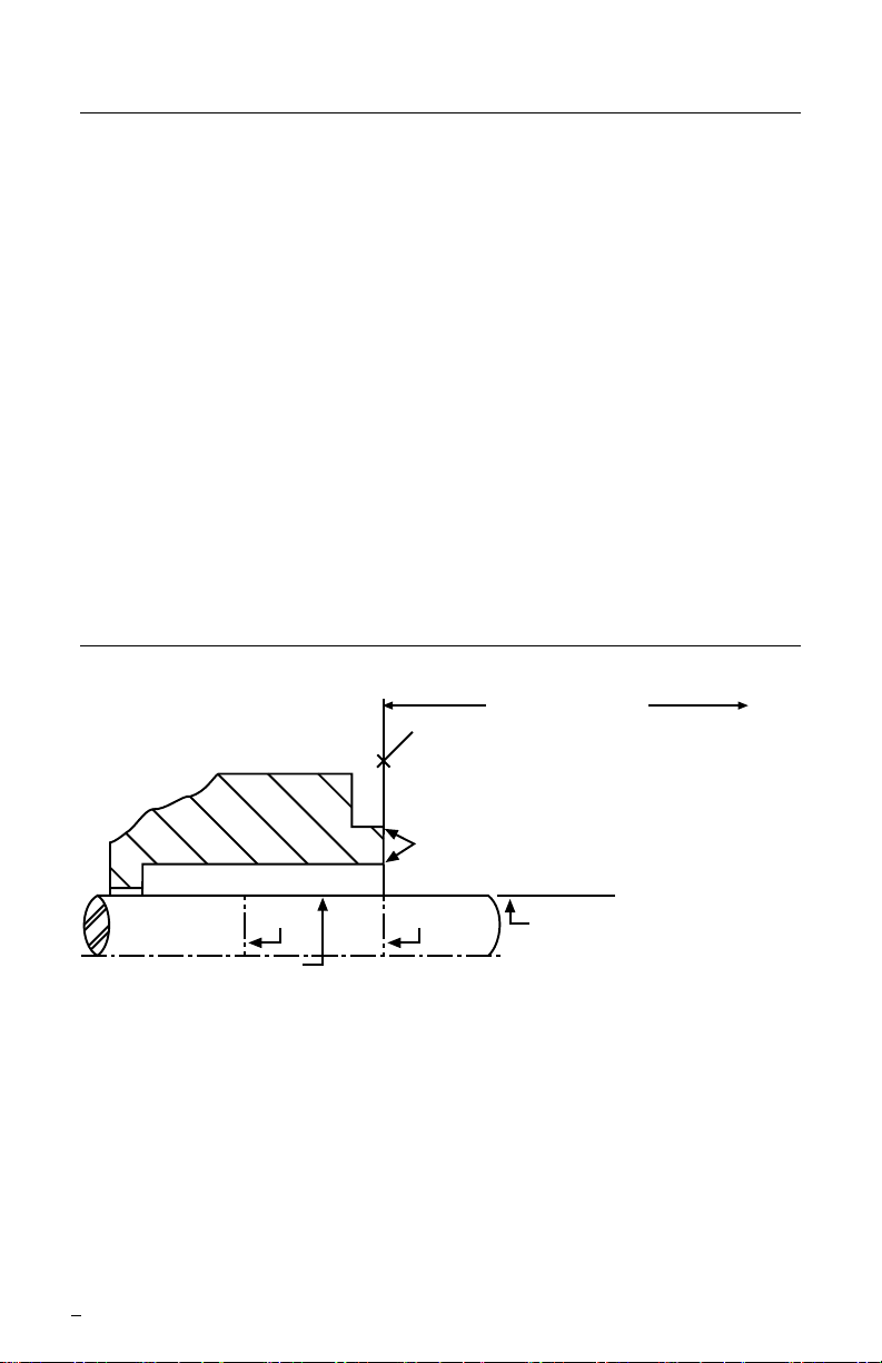
1.4 Check requirements for shaft, sleeve, and seal housing.
See Figure 1.
Seal Chamber Requirements Figure 1
To first obstruction
Face of seal housing to be square to the
axis of the shaft to within 0.0005 mm/mm
(0.0005 inch/inch) of seal chamber bore TIR
and have a 1.6
μm (63 μinch) R finish or better
a
Gland pilot can be at either of these
register locations, concentric to within
0.125 mm (0.005 inch) of shaft or
Seal housing bore to have 3.2 μm
(125 μinch) R finish or better
Sleeve or shaft finish to be
0.8 μm (32 μinch) R or better
• Bearings must be in good condition
• Maximum lateral or axial movement of shaft (end play) = 0.25 mm (0.010 inch) TIR
• Maximum shaft runout at face of seal housing = 0.05 mm (0.002 inch) TIR
• Maximum dynamic shaft deflection at seal housing = 0.05 mm (0.002 inch) TIR
a
Scribe
Mark B
a
The images of parts shown in these instructions may differ visually from the actual
parts due to manufacturing processes that do not affect the part function or quality.
sleeve OD TIR
Scribe
Mark A
Shaft or sleeve OD
+0.000 mm (+0.000 inch)
-0.050 mm (-0.002 inch)
+0.000 mm (+0.000 inch) API 610/682
-0.025 mm (-0.001 inch) DIN/ISO
2
ANSI
Page 3

1.5 Check assembly drawing included with the cartridge seal for specic
seal design, materials of construction, dimensions, and piping
connections.
1.6 Check shaft or sleeve OD, seal housing bore, and distance to
the rst obstruction to ensure they are dimensionally the same as
shown on the seal assembly drawing.
1.7 Check gland pilot and bolt holes to ensure they are adaptable to the
equipment and are the same as shown on the assembly drawing.
Many cartridge seal designs include setting devices that center the
seal around the shaft and do not require a gland pilot.
1.8 Handle all seal parts with care, they are manufactured to precise
tolerances. The rubbing contact faces of the rotating and stationary
faces are of special importance. These two sealing faces are lapped
at to within three light bands (34.8 millionths of an inch).
Keep the seal faces perfectly clean at all times.
2 Cartridge Seal Installation
2.1 Lubricate the shaft or sleeve lightly with lubricant provided with
the seal.
2.2 Install the complete cartridge seal assembly on the shaft.
2.3 For overhung pumps: Position the seal close to the bearing housing
with the seal oriented toward the pump. Install the pump back-plate
or seal housing and assemble the pump.
2.4 Position the cartridge gland against the seal housing face and
tighten the gland stud nuts up evenly, cross staggering the
adjustment of the nuts. The gland nuts should be torqued to a
maximum of 13 N-m (10 ft-lbs). Excessive gland nut pressure can
result in distortion of the stationary face.
2.5 For between bearings pumps: Assemble the bearings, coupling,
etc. and adjust the impeller so that the shaft is in its operating axial
position.
2.6 For end suction pumps: Adjust the bearings, coupling, and impeller
so that the shaft is in its operating axial position.
2.7 Tighten the set screws on the seal cartridge drive collar.
Note Any subsequent axial adjustment of the shaft requires resetting of
the seal.
3
Page 4

2.8 Disengage or remove setting devices. Eccentric washer or slotted
plate type setting devices should be repositioned clear of rotating
parts and locked to the gland in a neutral position. Centering type
devices cap screwed to the sleeve drive collar should be removed
and stored for future seal removal and repair. All setting device
types need to be reinstalled for resetting the seal when repositioning
the pump impeller.
2.9 See Operational Recommendations, paragraph 3 and 4, before
starting pump.
3 Operational Recommendations for Single
Cartridge Seal
3.1 Do not start up the equipment dry. Vent air from the casing of
the pump and the seal chamber before startup. Check the seal
assembly drawing for the recommended piping plan and follow any
special instructions. Plan 11 is a good default ush plan if none are
specied for horizontal pumps.
3.2 If the seal runs hot, check for proper seal setting, seal housing
dimensions, and check the bypass or ush line for obstructions.
Do not allow the equipment to run for any extended time if the seal
gets hot or squeals.
4
Page 5

4 Operational Recommendations for Dual
Cartridge Seal
4.1 A dual seal must be supplied a clean buffer/barrier uid compatible
with the product.
4.2 Dual pressurized seals must at all times maintain barrier uid
pressure at least 172 kPa (25 psig) above the maximum product
pressure in the seal chamber.
4.2 The recommended piping for a dual pressurized seal with the use
of a Supply Tank is shown in Figure 2, Plan 53A. Circulation from
an external source is shown in Figure 3, Plan 54. Other mechanical
seal support systems are also available from Flowserve.
4.3 Turn on any cooling water to the supply tank or other support
system.
4.4 Start-up the seal barrier uid system before starting pump.
4.5 Do not start up the equipment dry. Vent air from the casing of the
pump before startup.
4.6 If the seal runs hot, check for proper seal setting, seal housing
dimensions, and check the barrier uid system. Do not allow the
equipment to run for any extended time if the seal gets hot or
squeals.
For special problems encountered during installation, contact your
nearest Flowserve Sales and Service Representative or Flowserve
Authorized Distributor.
5
Page 6

Recommended Piping for Dual Liquid Lubricated Seals Figure 2
Plan 53A - Dual pressurized seal with circulation
through a supply tank
Pressure Source,
Normally Open
seal
end view
Outlet
Inlet
Fill Connection,
Normally Closed
Reservoir
Cooling Out
Drain,
Normally
Closed
Pressure Indicator (low)
Pressure Switch
(low)
Level switch (high)
Level Switch (low)
Cooling Coils
Cooling In
6
Page 7

Plan 54 - Dual seal circulation from an external source Figure 3
Outlet
seal
end view
Inlet
From /External
Circulating System
5 Repair
This product is a precision sealing device. The design and dimension
tolerances are critical to seal performance. Only parts supplied by
Flowserve should be used to repair a seal. To order replacement parts,
refer to the part code and B/M number. A spare backup seal should be
stocked to reduce repair time.
When seals are returned to Flowserve for repair, decontaminate the
seal assembly and include an order marked "Repair or Replace."
A signed certicate of decontamination must be attached.
A Material Safety Data Sheet (MSDS) must be enclosed for any
product that came in contact with the seal. The seal assembly will be
inspected and, if repairable, it will be rebuilt, tested, and returned.
7
Page 8

TO REORDER REFER TO
flowserve.com
B/M #
F.O
.
FIS122eng REV 10/13 Printed in USA
To find your local Flowserve representative
and find out more about Flowserve Corporation,
visit www.flowserve.com
Flowserve Corporation has established industry leadership in the design and manufacture of its products. When
properly selected, this Flowserve product is designed to perform its intended function safely during its useful life.
However, the purchaser or user of Flowserve products should be aware that Flowserve products might be used
in numerous applications under a wide variety of industrial service conditions. Although Flowserve can provide
general guidelines, it cannot provide specific data and warnings for all possible applications. The purchaser/user
must therefore assume the ultimate responsibility for the proper sizing and selection, installation, operation, and
maintenance of Flowserve products. The purchaser/user should read and understand the Installation Instructions
included with the product, and train its employees and contractors in the safe use of Flowserve products in connection
with the specific application.
While the information and specifications contained in this literature are believed to be accurate, they are supplied for
informative purposes only and should not be considered certified or as a guarantee of satisfactory results by reliance
thereon. Nothing contained herein is to be construed as a warranty or guarantee, express or implied, regarding any
matter with respect to this product. Because Flowserve is continually improving and upgrading its product design,
the specifications, dimensions and information contained herein are subject to change without notice. Should any
question arise concerning these provisions, the purchaser/user should contact Flowserve Corporation at any one of
its worldwide operations or offices.
© 2013 Flowserve Corporation
USA and Canada
Kalamazoo, Michigan USA
Telephone: 1 269 381 2650
Telefax: 1 269 382 8726
Europe, Middle East, Africa
Roosendaal, the Netherlands
Telephone: 31 165 581400
Telefax: 31 165 554590
Asia Pacific
Singapore
Telephone: 65 6544 6800
Telefax: 65 6214 0541
Latin America
Mexico City
Telephone: 52 55 5567 7170
Telefax: 52 55 5567 4224
 Loading...