

Page 1
Byron Jackson Type M
Double Mechanical Seal
Submersible Pumping Unit
USER INSTRUCTIONS:
INSTALLATION, OPERATION, MAINTENANCE
PCN=85392711 1042.293/9 • Edition June 2004
Page 2

Page 3

®
Byron Jackson Double Mechanical Seal Submersible Pumping Unit • 1042.293/9 • June 04
CONTENTS
PAGE
1
INTRODUCTION AND SAFETY ...................5
1.1 About the product and these user
instructions........................................... 5
1.2 CE marking and approvals ..................5
1.3 Disclaimer............................................5
1.4 Copyright ............................................. 6
1.5 Duty conditions....................................6
1.6 Safety................................................... 6
1.6.1 Safety symbols................................6
1.6.2 General safety instructions..............7
1.6.3 Personnel qualification, training
and protective clothing ....................7
1.6.4 Authorized and prohibited use.........7
2 TRANSPORT AND STORAGE.....................9
2.1 Consignment receipt and
unpacking ............................................ 9
2.2 Transport ........................................... 10
2.2.1 Safety instructions.........................10
2.2.2 Equipment and personnel
required ........................................ 10
2.2.3 Transport of the motor................... 10
2.2.4 Transport of the pump bowl
assembly....................................... 11
2.3 Storage and shipping......................... 12
2.4 Recycling and end of product life ...... 13
3 DESCRIPTION.............................................14
3.1 Configurations.................................... 14
3.1.1 General Description.......................14
3.1.2 Main Components.........................14
3.1.3 Motor serial number ...................... 14
3.5 Electrical requirements.......................17
3.5.1 General electrical requirements.... 17
3.5.2 Motor protection............................ 18
3.5.3 Short circuit protection .................. 18
4 INSTALLATION AND
UNINSTALLATION..................................... 19
4.1 Fitter ...................................................19
4.2 Equipment and personnel required....19
4.2.1 Equipment and tools supplied
with motor ..................................... 19
4.2.2 Equipment and tools to be
supplied by operator ..................... 19
4.2.3 Personnel required........................ 21
4.3 Hydraulic connection..........................21
4.4 Installation..........................................23
4.4.1 Safety instructions......................... 23
4.4.2 Sequence of installation................ 23
4.4.3 Prepare installation site................. 23
4.4.4 Arrange components for
installation..................................... 24
4.4.5 Inspect components...................... 25
4.4.6 Install motor .................................. 26
4.4.7 Install coupling.............................. 27
4.4.8 Install pump bowl assembly.......... 30
4.4.9 Install impeller............................... 32
4.4.10 Vent motor..................................... 33
4.4.11 Install power cable ........................ 35
4.4.12 Fasten the power cable to the
cable guard................................... 39
4.4.13 Install riser pipe, fasten power
cable to riser pipe.......................... 40
4.4.14 Connect power cable to
terminal box .................................. 43
4.4.15 Connect terminal box to main
power supply ................................. 43
4.5 Uninstallation......................................45
4.5.1 Safety instructions......................... 45
4.5.2 Uninstallation ................................ 45
3.2 Design of major parts.........................14
3.3 Performance and operating limits......15
3.3.1 Normal operating conditions..........15
3.3.2 Design changes ............................15
3.4 Preconditions at the installation
site .....................................................16
3.4.1 Survey of well................................ 16
3.4.2 Crooked well .................................16
3.4.3 Development of the well................16
3.4.4 Suction and submergence
requirements.................................16
3.4.5 Effect of pumping sand..................16
3.4.6 Effect of air or gas.........................16
3.4.7 Oxidizing and corrosive effects
of chemicals, air and gases...........16
5 COMMISSIONING STARTUP,
OPERATION AND SHUTDOWN................ 46
5.1 Safety instructions..............................46
5.2 Direction of rotation............................46
5.3 Starting the pump...............................46
5.3.1 First-time start-up of the pump...... 46
5.3.2 Normal start-up of the pump ......... 47
5.4 Running or operation..........................47
5.4.1 Performance and operating
limits ........................................ 47
5.4.2 Motor operation............................. 48
5.4.3 Starting frequency......................... 48
5.5 Stopping and shutdown......................49
Page 3 of 68
Page 4

®
Byron Jackson Double Mechanical Seal Submersible Pumping Unit • 1042.293/9 • June 04
6 MAINTENANCE ..........................................50
6.1 Safety instructions .............................50
6.2 Maintenance schedule....................... 50
6.3 Working substances and auxiliary
agents................................................51
6.4 Motor maintenance............................ 51
6.5 Pump maintenance............................51
6.6 Pump test run .................................... 51
6.7 Periodic testing of motor and pump... 52
6.8 Electrical tests of the motor ...............53
6.8.1 Insulation test................................ 53
6.8.2 Continuity testing...........................53
6.9 Spare parts........................................ 54
6.9.1 Recommended spares and
consumable items ......................... 54
6.9.2 Ordering spare parts ..................... 54
6.9.3 Storage of spare parts................... 54
6.10 Tools for repair and maintenance...... 55
7 FAULTS, CAUSES AND REMEDIES.........56
8 PARTS LIST AND DRAWINGS..................59
9 CERTIFICATION.........................................60
10 OTHER RELEVANT DOCUMENTATION
AND MANUALS ..........................................61
10.1 Change notes ....................................61
10.2 Abbreviations..................................... 61
11 GLOBAL CONTACT POINTS, EU CE
MARKER AND SERVICE CONTACTS ......62
12 APPENDIX...................................................63
12.1 Scope of delivery ...............................64
12.2 Data sheet .........................................65
12.3 Tightening torques............................. 66
12.4 Safety data sheet for motor oil...........67
Page 4 of 68
Page 5

®
f
r
Byron Jackson Double Mechanical Seal Submersible Pumping Unit • 1042.293/9 • June 04
1 INTRODUCTION AND SAFETY
1.1 About the product and these user
instructions
NOTE These user instructions must always
be kept close to the product's operating location of operation or directly
with the product so that they are
available to the operating personnel at
any time.
ned, developed and
Flowserve's products are d
manufactured with state-of-the-art technologies in
modern facilities. The pumping unit is produced
with great care and commitment to continuous
quality control, utilizing sophisticated quality techniques, and safety requirements.
Flowserve is committed to continuous quality im-
ent a
provem
formation about the product in its installation and
operation or about its support products, repair and
diagnostic services.
These instructions are intended to facilitate familiarization
Operating the product in compliance with these
instructions is important to help ensure reliability in
service and avoid risks. The instructions may not
take into account local regulations; ensure such
regulations are observed by all, including those
installing the product. Always coordinate repair activity with operations personnel, and follow all plant
safety requirements and applicable safety and
health laws/regulations.
NOTE These instructions should be read
These user instructions outline the general proce-
s
that must be observed to ensure long, trou-
dure
ble free performance of the pumping unit. However, it is assumed that plant personnel are familiar
with the basic principles and tools involved in the
installation, operation and maintenance of a pumping unit. Successful pumping unit operation is dependent on careful study of these user instructions
nd being at service for any further in-
with
the product and its permitted use.
prior to ins
and maintaining the equipment in
any region worldwide.
The equipment must not be put into
ce until all the conditions relat-
i
serv
ing to safety, noted in the instructions, have been met.
esig
t
alling, operating, using
and a well planned and observed maintenance
program.
In these user instructions, the numbers in brackets
umbers, e. g.: shaft button screw
are item
(806-2). Refer to the drawings in Chapter 8 "Parts
list and drawings", Page 59, for the position of the
respective item.
n
1.2 CE marking and approvals
It is a legal requirement that machinery and
equipment put into service within certain regions of
the world shall conform with the applicable CE
Marking Directives covering Machinery and, where
applicable, Low Voltage Equipment, Electromagnetic Compatibility (EMC) and Pressure Equipment
Directive (PED).
Where applicable, the Directives and any addi-
ovals cover important safety aspects
tional App
relating to machinery and equipment and the satisfactory provision of technical documents and safety
instructions. Where applicable, this document incorporates information relevant to these Directives
and Approvals.
To check if the approvals apply and if the product
itself is CE marked, check
markings and the Certification, see Section 9
"Certification", Page 60.
r
the seri
al number plate
1.3 Disclaimer
Information in these user instructions is believed
to be reliable. In spite of all the efforts o
Flowserve Pump Division to provide sound and all
necessary information the content of these use
instructions may appear insufficient and is not
guaranteed by Flowserve as to its completeness
or accuracy.
Flowserve manufactures products according to
International Quality Management System Standards as certified and audited by external Quality
Assurance organizations. Genuine parts and accessories have been designed, tested and incorporated into the products to help ensure continued
product quality and performance in use.
As Flowserve cannot test parts and accessories
ced from other vendors the incorrect installa-
r
sou
tion of such parts and accessories may adversely
affect the performance and safety features of the
products. The failure to properly select, install or
use authorized Flowserve parts and accessories is
considered to be misuse. Damage or failure
caused by misuse is not covered by Flowserve's
warranty. In addition, any modification of
Page 5 of 68
Page 6
®
r
r
Byron Jackson Double Mechanical Seal Submersible Pumping Unit • 1042.293/9 • June 04
Flowserve products or removal of original components may impair the safety of these products in
their use.
1.4 Copyright
All rights reserved. No part of these user instructions may be reproduced, stored in a retrieval system or transmitted in any form or by any means
without prior permission of Flowserve Pump Division.
1.5 Duty conditions
This product has been selected to meet the specifications of your purchaser order. The acknowledgement of these conditions has been sent separately to the purchaser. A copy should be kept with
these user instructions.
NOTE The product must not be operated
beyond the parameters specified fo
the application.
If there is any doubt as to the suitability of the product for the application intended, contact Flowserve fo
advice, quoting the serial number.
If the conditions of service on your purchase order
are changed (for example liquid pumped, temperature or duty) it is requested that the user seeks our
written agreement before start up.
1.6 Safety
1.6.1 Safety symbols
These user instructions contain specific safety
symbols where non-observance of an instruction
would cause hazards.
Safety symbol and safety
word
DANGER This symbol indicates an
This symbol indicates a
CAUTION This symbol indicates a
The following symbols may be added to the above symbols
CAUTION This word indicates a situation
NOTE This sign is not a safety symbol
This symbol indicates a
This symbol indicates a
Table 1 Safety symbols in these user instructions
Meaning
imminent hazardous situation.
The situation, if not avoided, will
result in death or serious injury.
potentially hazardous situation.
The situation, if not avoided,
could result in death or serious
injury.
potentially hazardous situation.
The situation, if not avoided,
could result in minor or moderate
injury.
which, if not avoided, could
damage the equipment.
but indicates an important
instruction in the assembly
process.
potentially hazardous situation
due to hazardous and toxic fluid.
The situation, if not avoided,
could result in death or serious
injury.
This symbol indicates a
potentially hazardous situation
due to strong magnetic field.
The situation, if not avoided,
could result in death or serious
injury to persons with pacemaker
implant.
Further, the situation could
damage instruments and stored
data sensitive to magnetic fields.
potentially hazardous situation in
an explosive atmosphere
according to ATEX.
The situation, if not avoided in
the hazardous area, could cause
an explosion.
Page 6 of 68
Page 7
®
r
r
A
Byron Jackson Double Mechanical Seal Submersible Pumping Unit • 1042.293/9 • June 04
1.6.2 General safety instructions
NOTE Always follow
• legal regulations
• plant regulations
• these user instructions
concerning safety.
Absolutely heed all information placed directly on
the pumping unit and given in Chapter 12.2 "Data
sheet", as for example
• rotation arrow
• labeling of connections
• rating plate.
Danger of injury by
• knocking against parts, tools o
equipment
• jamming fingers or hands in o
between parts, tools or equipment
• dropping parts, tools or equipment on parts of the body.
DANGER
ll work on the electrical system
may only be performed by qualified
electricians!
All work on the hydraulic connections may only be performed by
qualified fitters.
Protective clothing
During transport, installation and removal of the
pumping unit, all personnel must wear
• helmet
• safety boots
•
protective gloves
During operation of the pumping unit at the control
center, all personnel must wear
•
protective gloves
NOTE Also follow
• legal regulations
• plant regulations
concerning protective clothing.
1.6.3 Personnel qualification, training and protective clothing
Personnel qualification and training
All personnel involved in the operation, installation,
inspection and maintenance of the pumping unit
must be qualified and authorized to carry out the
work involved.
If the personnel in question do not already possess
the necessary knowledge and skill, appropriate
training and instruction must be provided. If required, the operator may commission the manufacturer / supplier to provide applicable training.
Always co-ordinate repair activity with operations
and health and safety personnel, and follow all
plant safety requirements and applicable safety
and health laws and regulations.
1.6.4 Authorized and prohibited use
The safe operation of the pumping unit can only be
guaranteed if it is operated as authorized.
The only authorized utilization of the pumping unit
is to pump water from a well. The pumping unit is
to be operated submerged in water.
NOTE Not all components or sub-
assemblies of a pumping unit are
necessarily supplied by Flowserve
or part of this delivery.
These user instructions apply only
to the components or subassemblies supplied by Flowserve
in this delivery, see Chapter 12.1
"Scope of delivery".
By not heeding this user instructions, product liability is rendered void.
Page 7 of 68
Page 8

®
Byron Jackson Double Mechanical Seal Submersible Pumping Unit • 1042.293/9 • June 04
Non-authorized utilization of the pumping unit includes:
• operating the pumping u
nit in a known mal-
functioning state
• operating the pumpin
g unit in conditions other
than those given in Chapter 3.3.1 "Normal operating conditions", Page 15.
• making modifications of the pumping unit that
are not auth
orized by Flowserve
• using spare parts that are not authorized by
Flowse
rve.
CAUTION Alterations to the pumping unit are
only
permitted a
fter written permis-
sion by Flowserve.
Only use spare parts that have been
autho
rized b
y Flowserve.
Flowserve is not liable for any dam-
ause
age c
d by the use of parts ob-
tained from third parties.
Page 8 of 68
Page 9

®
Byron Jackson Double Mechanical Seal Submersible Pumping Unit • 1042.293/9 • June 04
2 TRANSPORT AND STORAGE
2.1 Consignment receipt and unpack-
ing
A submersible pumping unit consists of
• Motor
• Pump bowl assembly
• Non-return valve
• Powe
• Riser pipe
• Cable or bracket to fasten the motor power
• Wellhead (surface plate)
• Terminal box or jun
• Tools for inst
NOTE Not all components or sub-
Flowserve generally ships the pumping unit in two
packa
• Main compon
• Tools described in
All components and parts are suitably protective
ppe
wra
ate.
The motor is shipped nearly completely filled with
oil, with
mounted outside of the motor to allow thermal expansion and contraction of the motor oil.
r cable
(discharge column)
cabl
e onto the riser pipe
ction box
allation and maintenance.
assemblies
of a pumping unit are
necessarily supplied by Flowserve
or part of this delivery.
These user instructions apply only
to the c
omponen
ts or subassemblies supplied by Flowserve
in this delivery, see Chapter 12
"Scope of delivery".
s:
ge
ents described in Chapter 3.1.2
"Main Components", Page 14.
Chapter 4.4.4 ”Arrange
components for installation", Page 24.
d, crated or mounted on skids as appropri-
oil expansion bag (shipping bladder)
an
The power cable, if included in the delivery, is
ship
ped on a reel with a sh
ipping cap or other pro-
tective covering installed to protect the connectors.
Immediately after receipt of the equipment
1. Uncrate all parts.
Check all crates, boxes and wrappings for any
accessorie
s or spare parts which may be
packed separately with the equipment or attached to side walls of the box or equipment.
2. Check the scope of delivery.
• Che
ck the delivery against the delivery
and shippi
ng documents for its com-
pleteness.
Each product has a unique serial num-
at this number corresponds
ber. Ch
eck th
with that advised.
NOTE Make sure you can always quote
t
each par
's serial number in correspondence and when ordering
spare parts or further accessories.
• Ins
pect the delivery for trans
damage.
Immediately report any shortage and or dam-
age to Flowserve and the ship
ping company.
Claims must be reported in writing within one
month of receipt of the equipment. Flo
does not accept latter claims.
3. Check the available power against the res given on the motor data plate and
ment
quire
in Chapter 12.2 "Data sheet".
If the equipment is to be stored
• continue with Chapter 2.3 "Storage and ship-
ping", Page 1
2.
If the equipment is to be installed
• contin
ue with Chapter 4.4 "Installation",
Page 23.
portation
wserve
Page 9 of 68
Page 10
®
Byron Jackson Double Mechanical Seal Submersible Pumping Unit • 1042.293/9 • June 04
2.2 Transport
2.2.1 Safety instructions
Transport is the process of moving the pumping
unit or its components from the installation site to a
storage site, maintenance site or repair site, or vice
versa.
During transport, always
• Work carefully to avoid accidents.
• Handle equipment carefully.
• Be sure lifting devices are in good condition
and are capable of safely handling the
weights to be lifted.
• Mark and seal off the transport route so that
unauthorized personnel do not enter the danger area.
• Take precautions to prevent foreign materials
or dirt from entering the working parts of pump
and motor.
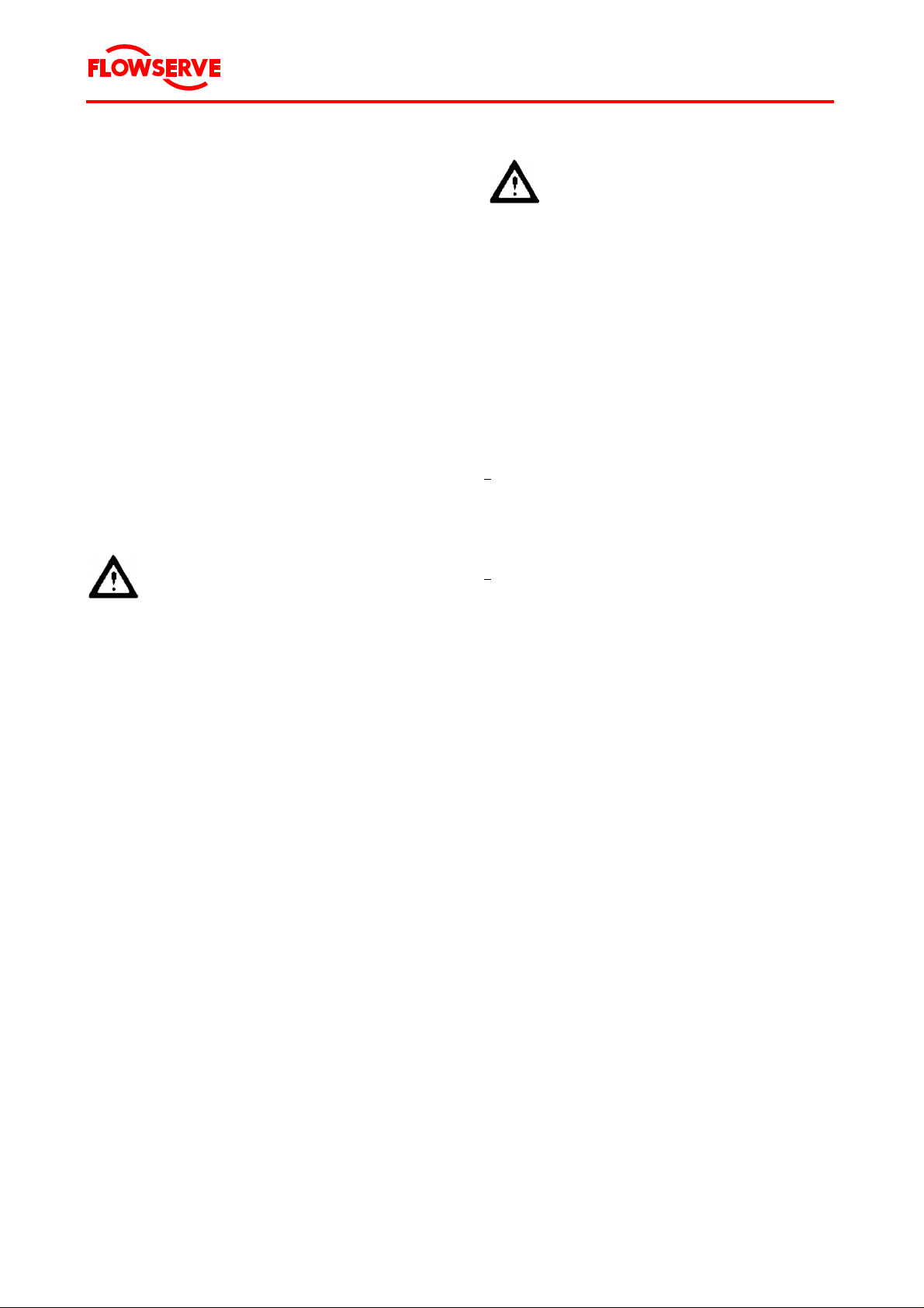
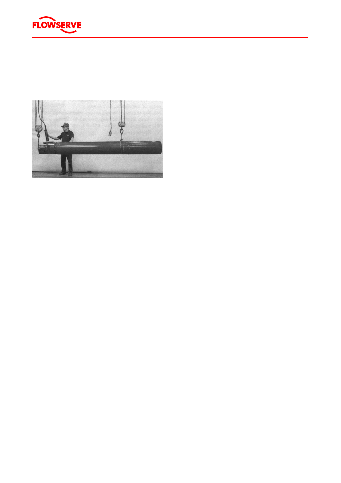
2.2.3 Transport of the motor
Do not raise or move the motor by
the power cables!
CAUTION The motor is a dynamically bal-
anced machine and should be handled accordingly.
Take precautions to prevent foreign
materials or dirt from entering the
working parts of the motor.
1. Refer to Figure 1.
Place hitching line under lifting lugs.
Take care that the hoist has an adequate carrying force. For weight see
Chapter 12.2 "Data sheet".
Never step under floating load.
Watch for and avoid overhead ob-
structions including power lines.
2.2.2 Equipment and personnel required
Provide the following equipment for the transport:
• Portable crane with adequate carrying force.
For weight see Chapter 12.2 "Data sheet.
• Also see Chapter 4.2 "Equipment and personnel required", Page 19.
Flowserve recommends that 2 persons plus 1
crane operator perform the transport.
Figure 1 Hitching line under lifting lugs
Page 10 of 68
Page 11
®
Byron Jackson Double Mechanical Seal Submersible Pumping Unit • 1042.293/9 • June 04
2. Refer to Figure 2.
Place a wire around the motor. The wire is to
be positioned between stator and lower casing, approx. 1/3 from bottom of motor.
Figure 2 Lifting motor for installation
3. Lift the motor horizontally by 2 points.
4. Transport the motor horizontally to the installation or storage site.
5. Carefully lower the motor at the respective
site and place it on the floor.
If the motor is to be stored:
• Continue with Chapter 2.3 "Storage and shipping", Page 12.
If the motor is to be installed in a well:
• Continue with Chapter 4 "Installation",
Page 19.
2.2.4 Transport of the pump bowl assembly
NOTE Not all components or sub-
assemblies of a pumping unit are
necessarily supplied by Flowserve
or part of this delivery.
These user instructions apply only
to the components or subassemblies supplied by Flowserve
in this delivery, see Chapter 12.1
"Scope of delivery".
CAUTION Use care to prevent bumping, push-
ing, or scraping of pump bowl assembly parts, especially the shafts,
or other machined surfaces.
Take precautions to prevent foreign
materials or dirt from entering the
working parts of the pump bowl assembly.
NOTE The following description refers to
pumps without auxiliary carriers.
Should the pump be delivered on an
auxiliary carrier, refer to the pump
manual for transportation instructions.
1. Connect the pump
• directly to the hoists, or
• to the cross-beam
If the motor is to be maintained:
• Continue with Chapter 6 "Maintenance",
Page 50.
Page 11 of 68
of a portable crane.
2. By means of the crane, carefully lift the pump
and move it to the desired site.
If the pump bowl assembly is to be stored:
• Continue with Chapter 2.3 "Storage and shipping", Page 12.
If the pump bowl assembly is to be installed in a
well:
• Continue with Chapter 4 "Installation",
Page 19.
If the pump bowl assembly is to be maintained:
• Continue with Chapter 6 "Maintenance",
Page 50.
Page 12

®
Byron Jackson Double Mechanical Seal Submersible Pumping Unit • 1042.293/9 • June 04
2.3 Storage and shipping
For the removal of the pump from the well see
Chapter 4.5 "Uninstallation", Page 45, if necessary.
Requirements for the storage area
• Safe
• Clea
• Away from extended p
n
eriods of direct sunlight
• Well ventilated
• Dry
Air humidity:
................................40 % to 60 %
• Cool
Air temperatur
e for motors
originally filled by Flowserve:...+50 °C to -5 °C
CAUTION Always s tore mot or and pump bowl
assembly
separately
.
Prepare motor for storage or shipping after removing the motor from the well
1. Arrange the motor horizontally.
2. If pump and coupling are to be stored or
shipped sep
nents on motor shaft.
3. Install power terminal shipping cap (112),
power te
shipping caps (112-1).
4. If the motor is to be stored in a vertical position, proceed
a. Remove the adapter bracket (808).
b. Drill a vent hole in the motor shipping cap
(112-1
If the motor is returned to factory at a
later time, se
plug.
5. If the motor is to be returned to the factory,
eed as follows:
c
pro
a. Remove motor half-coupling (529) or mo-
tor one-pie
b. Lubricate shaft with some form of pene-
trating oil.
c. Place coupling and components in motor
ship
minal gasket (744-6) and bolt cap securely in place.
arately: Install coupling compo-
nal gasket (744-6), and motor
rmi
as follo
ws:
).
al the vent hole by a pip
ce coupling (531).
ping cap
(112-1) with its power ter-
e
d. Elevate motor over a sump or drum to
nd
drain oil a
water from motor.
e. Remove lower casing drain plug (806)
from bottom of motor, then remove vent
plugs (806-4 and 806-5) at top of motor
and allow motor to fully drain.
f. Replace drain and vent plugs.
Prepare pump bowl assembly for storage or
shipping
NOTE Not all components or sub-
assemblies
of a pumping unit are
necessarily supplied by Flowserve
or part of this delivery.
These user instructions apply only
to the c
omponen
ts or subassemblies supplied by Flowserve
in this delivery, see Chapter 12.1
"Scope of delivery".
NOTE The following description refers to
w
pumps
ithout auxiliary carriers.
Should the pump be delivered on an
y
auxiliar
carrier, refer to the pump
manual for storage and shipping
instructions.
1. Install blocks in the strainer to restrain the
pump shaft.
This prevents shaft end float and possible in-
e during handling.
ternal da
mag
2. Make sure the bowl assembly is thoroughly
dry.
3. Install suitable covers to seal off all openings.
Page 12 of 68
Page 13
®
V
Byron Jackson Double Mechanical Seal Submersible Pumping Unit • 1042.293/9 • June 04
Store pumping unit
NOTE The following description refers to
pumps without auxiliary carriers.
Should the pump be delivered on an
auxiliary carrier, refer to the pump
manual for storage and shipping
instructions.
Store the pumping unit as follows:
• Motor:
Preferably vertically
Filled with oil
• Pump bowl assembly with rubber bearing
bushes:
Vertically
• Pump bowl assembly with other than rubber
bearing bushes:
Preferably vertically
DANGER
Horizontally stored motors and
pump bowl assemblies must be secured against rolling.
ertically stored motors and pump
bowl assemblies must be secured
by appropriate means in this storage position to prevent tipping over.
• Power cable:
Leads protected from moisture
NOTE Do not bend power cable during
storage.
Maintenance during storage
• Storage up to four weeks
At the beginning and end of the storage pe-
riod: Carefully check the motor to be sure
there are no signs of oil leakage.
• Storage between 1 and 24 months
Maintenance of the motor, every 6 to 8 weeks:
1. Remove the motor shipping cap (112) at
the motor.
3. Mount the motor shipping cap (112) to
the motor.
Maintenance of the pump, every 6 to 8 weeks:
1. Remove the discharge housing and the
non-return valve for the pump shaft.
2. Turn the pump shaft several times by
means of a wrench.
4. Mount the discharge housing and nonreturn-valve to the pump.
• Storage for over 24 months
After a storage of more than 24 months, we
recommend a complete visual inspection at
our main factory or at your nearest Flowserve
representative.
Shipping
Ship motor and pump bowl assembly
• in non-airtight protection film
• in wooden box or similar transport packaging.
2.4 Recycling and end of product life
At the end of the service life of the pumping unit or
its parts, the relevant materials and parts should be
recycled or disposed of using an environmentally
acceptable method and heeding local regulations.
If the product contains substances which are harmful to the environment, these should be removed
and disposed of in accordance with local regulations. This also includes the liquids and or gases in
the "seal system" or other utilities.
DANGER
Make sure that hazardous sub-
stances are disposed of safely and
that the correct personal protective
equipment is used.
The safety specifications must be in
accordance with the local regulations at all times.
Hazardous substances in the pumping unit are
• Motor oil
2. Turn the motor shaft several times by
means of a wrench.
Page 13 of 68
Page 14

®
Byron Jackson Double Mechanical Seal Submersible Pumping Unit • 1042.293/9 • June 04
3 DESCRIPTION
3.1 Configurations
3.1.1 General Description
The Flowserve submersible pumping unit is a
combination of
• a vertic
chanical seal
• a vertical pump bowl a
designed for sustained operation submerged in
water.
The
pump bowl assembly.
The rotating element of the pump bowl assembly is
driven from the bottom
connected to the motor shaft by a coupling.
Power is supplied to the motor through a submarine po
we
and extends to the starting equipment. Motor and
pump bowl assembly are connected to the riser
pipe. The riser pipe is threaded or flanged and
coupled in random lengths and the entire unit is
coupled to a wellhead assembly.
Each pumping unit has been individually manufac-
ccording to the special requirements of the
a
tured
customer. The technical data is given in Chapter
12.2 "Data sheet".
al, oil filled motor with double me-
ssembly
motor is positioned directly below the
where its extended shaft is
r cable which is fastened to the riser pipe
These user instructions apply only
to the componen
ts or subassemblies supplied by Flowserve
in this delivery, see Chapter 12.1
"Scope of delivery".
3.1.3 Motor serial number
The motor serial number is on the name plate on
the stator.
3.2 Design of major parts
The motor is filled with, lubricated and cooled by a
special mineral oil of high dielectric strength.
This oil
• allows high efficiency rotor-stator design,
• provides
qualities, and
• protects the motor from internal corrosion.
CAUTIO
excellent insulation and lubrication
N The oil used in this pumping unit is
specifie
d in Chap
ter 12.2 "Data
sheet".
Use of other oil
3.1.2 Main Components
A pumping unit consists of
• Motor
• Pump bowl assembly
• Non-return valve
• Power cable
• Riser pipe
(discharge column)
• Cable or bracket to fasten the motor power
cabl
e onto the riser pipe
• Wellhead (surface plate)
• Terminal box or jun
• Tools for inst
ction box
allation and maintenance.
NOTE Not all components or sub-
assemblies of a pumping unit are
necessarily supplied by Flowserve
or part of this delivery.
• ma
y cause damage to the
pumping unit
• renders Flo
wserve's warranty
void.
The motor does not require periodic oil changes.
The oil is circulated within the motor by pumping
action of the
thrust bearing disc. Separation between the motor oil and pump liquid at the shaft
exit is maintained by two mechanical seals.
The motor is pressure compensated.
The double mechanical seal system uses a pres-
balan
sure
ce process to equalize the pressure differential across the seals, minimizing leakage and
providing years of maintenance free service. The
inner seal diverts any pumped fluid leakage via a
communication line to a storage reservoir at the
bottom of the motor. The motor is vented to the
well by the balance line. As the oil expands, some
oil is pushed out of the motor through the balance
tube. As the oil cools down, pumped fluid is drawn
back into the lower casing at the bottom of the motor through the balance tube.
Page 14 of 68
Page 15

®
r
f
Byron Jackson Double Mechanical Seal Submersible Pumping Unit • 1042.293/9 • June 04
3.3 Performance and operating limits
3.3.1 Normal operating conditions
Operating purpose
Submersible pumps serve to transport water under
the operating con
ditions described in the following.
tion
Opera
• Operation
wit
hin prescribed voltage tolerance,
see Chapter 12.2 "Data sheet"
• No operation against closed slide valve
• Permissible o
perational range: 50 % to 120 %
of the optimal delivery rate
CAUTION Other uses, operating purposes o
operating conditions must be
agreed upon by Flowserve.
Water characteristics
• Water temperature: .............
• Sand content:
......................Maximum 25 mg/l
Also see Chapter 3.4.3 "
well", Page 16, and Chapter 3.4.5 "Effect of
pumping sand", Page 16.
• No impuritie
s which could lead to deposits
and blockages within the pump or to deposits
on the motor surface.
Also see Chapter 3.4.6 "Effect of air or gas",
nd Chapter 3.4.7 "Oxidizing and
16 a
Page
corrosive effects of chemicals, air and gases",
Page 16.
• No occurrence of water hammer
CAUTIO
N At higher surrounding temperatures
and/or lo
er flow velocities on the
w
external motor surfaces, or if there
is risk of clogging, special measures for heat dissipation are required.
Inform Flowserve of the surrounding conditio
ns.
See Chapter 12.2
"Data sheet"
evelopment of the
D
• Observation of the
starting frequency
maximum permissible
Installation position
Take the following criteria into account when determinin
• Vertical installation in a
g the installatio
n position and depth:
well above the filter
line, so that a perfect flow is guaranteed along
the external motor wall.
• Sufficient water cover
• A static wat
er level at least 2 m above the
pump exit
• A dynamic water level above the suction
hou
sing, taking into account the required net
positive suction head for the pump (see Chapter 12.2 "Data sheet")
• Flow rate (see Cha
• Supply cond
pter 12.2 "Data sheet")
itions of the pumping medium
(dependent upon the installation conditions)
CAUTION The pumping unit should be in-
stalled above the
well filter.
If this is not possible, prevent direct
w
suction
ithin the filter line by suitable measures (e.g. blind tube in
the filter, outer pump mantle, pump
with sand protection jacket.
Flo
of the p
application and confirm its use, i
applicable.
Pumping unit
• Corre
ctly selected and adjusted motor protec-
tion
wserve will check the suitability
ump
ing unit for its planned
Page 15 of 68
3.3.2 Design changes
Alternation or addition of the pumping unit may
c
only take pla
• by Flowserve,
e
or
• after written consent by Flowserve.
Page 16

®
Byron Jackson Double Mechanical Seal Submersible Pumping Unit • 1042.293/9 • June 04
3.4 Preconditions at the installation
site
3.4.1 Survey of well
Always sound the well to make sure it is deep
enough to permit install
consisting of pump bowl assembly and motor. If
the exact diameter and depth of the well casing is
not known, "cage" the well following the procedure
outlined in Chapter 3.4.2 "Crooked well", Page 16.
Experience indicates that many wells have more
stri
that one
ng of casing installed and frequently
the lower sections are smaller in diameter than the
surface casing. Be certain the submersible pumping unit will pass into the well freely and hang well
above of the well bottom.
3.4.2 Crooked well
A well that is known to be crooked and that has not
ly accommodated a pumping unit of com-
previou
s
parable size must be "caged" before the submersible pumping unit is installed.
1. Prepare a cage of the same length and di-
the combined motor and pump
ameter a
s
bowl assembly, with 12 m to 15 m (40 feet to
50 feet) of the proper size of riser pipe.
2. Lower the cage into the well to the point at
h the pumping unit is to be placed.
c
whi
3. If the cage can be lowered to this point with-
out touching
the inner wall of the well, the
submersible pumping unit can be installed.
3.4.3 Development of the well
Do not use a new pumping unit to develop the well.
Developing, surging and freeing the well of sand
s
are con
idered a part of the well drillers contract
and should be accomplished by the use of a test
pumping unit.
ation of the pumping unit
maximum well draw-down level, although some
installations may require more submergence.
3.4.5 Effect of pumping sand
Flowserve does not guarantee the pumping unit to
be resistant
against the erosive action of sand, silt
or other abrasive materials suspended in water.
Pumping sand will adversely affect the motor be-
e the vibration produced in a worn pump bowl
s
cau
assembly will be transmitted to the motor and
could result in a shortened motor life.
3.4.6 Effect of air or gas
The presence of gases in the water may reduce
a
city and head of the pumping unit, thus de-
cap
creasing the hydraulic performance. Further, air or
gas in the water will cause deterioration of materials of the pumping unit sooner than under normal
conditions.
3.4.7 Oxidizing and corrosiv e effects of
r and gases
chemicals, a
i
Even if the composition of the pumped water is
n due to chemical analysis, it is not always
know
possible to predict the corrosive action of water on
the metals of the pumping unit.
In addition to chemicals, water may also contain
entrain
ed air or ga
ses that have a definite oxidizing
or corrosive action of their own. This action is accentuated by high velocities within the pump.
Such conditions are not recognizable in the chemical analysis of the water.
Conforming with the Standards of the Hydraulic
Institute of th
e United States and the p
ractice of all
reliable pump manufacturers, Flowserve does not
guarantee its pumps and motors to be resistant
against corrosive or electrolytic action.
Should you require motors or pumps to perform
unde
r oxidizi
ng or corrosive conditions, contact
Flowserve for further information.
3.4.4 Suction and submergence requires
ment
Pumping th
unit br
e well at a rate at which the pumping
eaks suction will cause pump deterioration.
It is suggested that a method be provided for keeping a record of the water level above the suction
inlet.
The minimum submergence recommended is 3 m
(10
feet) of
riser pipe submergence below the
Page 16 of 68
Page 17
®
Byron Jackson Double Mechanical Seal Submersible Pumping Unit • 1042.293/9 • June 04
3.5 Electrical requirements
3.5.1 General electrical requirements
The Byron Jackson submersible motor is designed
for across-line start, eliminating the need for reduced voltage starting equipment. Maximum current inrush when the motor is connected across the
line at full voltage will be limited to about 700 % of
the rated load current.
Because starting the motor at full voltage results in
high starting torque, the motor accelerates to operating speed very rapidly (within 0.8 seconds, typically), and current consumption correspondingly
drops to normal. The rated power requirements of
the motor are stated on the pump nameplate located on the wellhead.
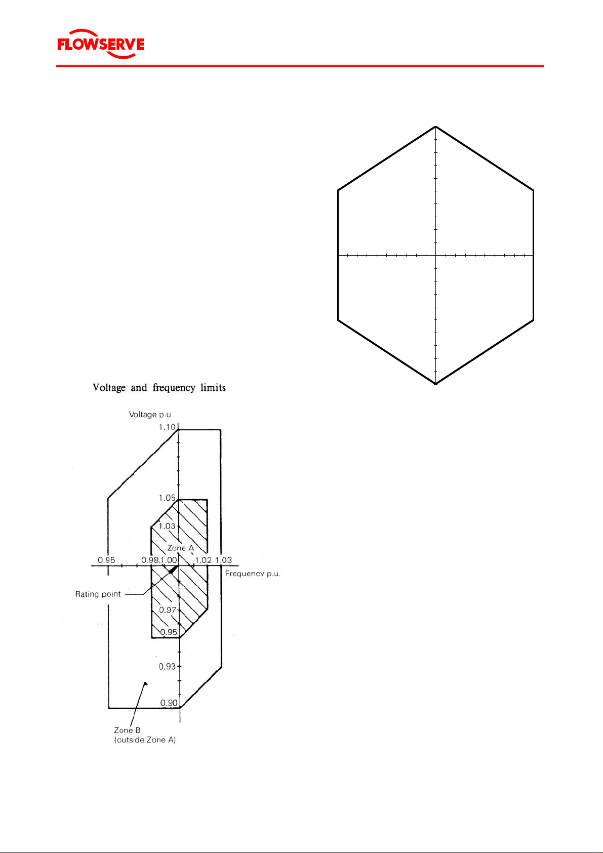
Allowed combinations of voltage and frequency
variations during operation are classified according
IEC 60034 as being either Zone A or Zone B
(Figure 3) or according NEMA (see Figure 4).
Voltage and frequency limits
0,1
0,08
0,06
0,04
0,02
0
-0,05 -0,04 -0,03 -0,02 -0,01 0 0,01 0,02 0,03 0,04 0,05
-0,02
Voltage Variation p.u.
-0,04
-0,06
-0,08
-0,1
Frequency Variation p.u.
Figure 3 Voltage and frequency limits acc. IEC 60034
Figure 4 Voltage and frequency limits acc. NEMA
The motor is capable of performing its rated torque
continuously within Zone A, but need not comply
fully with its performance at rated voltage and frequency (see rated point in Figure 3), and may exhibit some deviations. Temperature rises may be
higher than at rated voltage and frequency. For
conditions at the extreme boundaries of Zone A,
the temperature rises and temperatures may exceed the specified limits of temperature rise and
temperature by approximately 10 K.
Operation outside Zone A (within Zone B) may exhibit greater deviations from its performance at
rated voltage and frequency than in Zone A. Temperature rises may be higher than at rated voltage
and frequency and most likely will be higher than
those in Zone A. Extended operation at the
perimeter of Zone B is not recommended.
Low voltage is a serious problem since the operating motor current is increased, resulting in additional motor heating. However, the motor is designed to operate continuously at 110 % of rated
current, so that some reduction in voltage can be
tolerated as long as it is not also accompanied by
an overload of the motor.
Page 17 of 68
Page 18
®
f
Byron Jackson Double Mechanical Seal Submersible Pumping Unit • 1042.293/9 • June 04
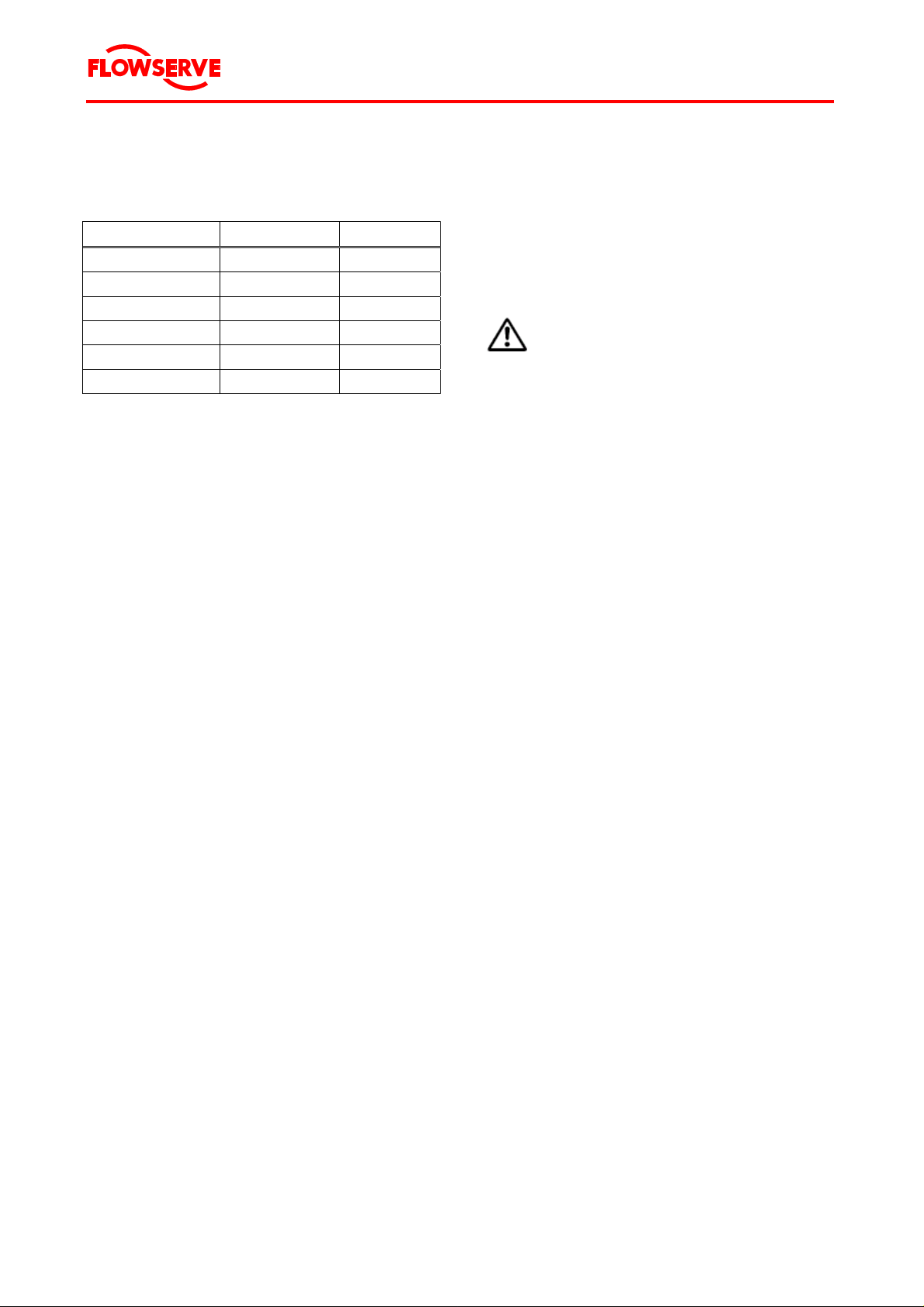
With variations in voltage, the motor characteristics
will, in general, vary as given in Table 2.
Voltage 110 % 90 %
Speed Increase 1 % Decrease 1.5 %
Efficiency (full load) Increase 0.5 % Decrease 1 %
Power factor (full load) Decrease 3 % No change
Current (starting) Increase 11 % Decrease 11 %
Current (full load) Decrease 8 % Increase 11 %
Temperature Decrease 2 % Increase 5 %
Table 2 Motor characteristics at varying voltage
Rated or full load current refers to the amperage
drawn by the motor at nameplate output, frequency
and voltage at the motor terminals. The maximum
allowable current (except momentarily at start-up)
is 110 % of the rated value.
The voltage on all three phases should be evenly
balanced as closely as can be read on the usually
available commercial voltmeter, because the current unbalance will be in the order of 6 to 10 times
the voltage unbalance. Running the motor with the
unbalanced voltage will lead to increased temperature and decreased motor life time, and therefore
must be avoided.
The value given in Chapter 12.2 "Data sheet", is a
standard value for the operating point. If the actual
operational current in the operating point of the
pump bowl assembly lies under this given value,
the switch must be adjusted lower so that there is
effective protection and malfunctions can be indicated in time.
DANGER
Do not set the motor protection ad-
justment higher than the highest permissible value given in Chapter 12.2
"Data sheet".
Do not test the perfect functioning o
a motor protection switch by intentional single-phasing.
3.5.3 Short circuit protection
To prevent short circuiting of the power cable and
the motor, safety measures must be taken according to local ordinances.
Guide values for the safety fuse sizes can be taken
from Chapter 12.2 "Data sheet".
Poor voltage regulations of an engine-driven generator, if the power is derived from such a source,
can be very disadvantageous to the motor. Thus,
Flowserve assumes no responsibility for pumping
units operated on such equipment unless agreed
on in writing.
Also, because of the unpredictable characteristics
and past experiences associated with the use of
phase converters, Flowserve must void all guarantees for applications that incorporate these devices
as a means of obtaining three phase power.
3.5.2 Motor protection
To protect the motor against power overload, an
inverse time-lag overload relay must be provided,
sensitive to phase failure and which compensates
for temperature.
The over current relay for the switchgear and the
safety fuses can be adjusted or selected according
to Chapter 12.2 "Data sheet".
The adjustment of the motor protection switch
(thermally delayed over current relay) must be
done according to the value given in Chapter 12.2
"Data sheet".
Page 18 of 68
Page 19

®
Byron Jackson Double Mechanical Seal Submersible Pumping Unit • 1042.293/9 • June 04
4 INSTALLATION AND UNINSTALLA-
TION
4.1 Fitter
It is recommended that the services of Flowserve
be employed for the installation and initial starting
of a Byron Jackson pump.
Such service will ensure the purchaser that the
properly installed, and will provide an
equipm
ent is
excellent opportunity for the plant operator to receive special instructions relative to the pumping
unit.
4.2 Equipment and personnel re-
quired
4.2.1 Equipment and tools supplied with mo-
tor
Equipment and tools supplied with motor and
half coupling
• Hex so
(806-2)
• Hex socket wrench for coupling set screw
(806
• Hex socket wren
• Hex socket wren
cket wrench for shaft button screw
-1)
ch for vent plug (806-4)
ch for vent plug (806-5)
4.2.2 Equipment and tools to be supplied by
opera
tor
Provide the followin
g equipment and tools:
• Lifting Equipment.
Must be of sufficient strength and rigidity to lift
the com
lete unit safely, see Table 3,
p
Page 20, and of sufficient height to allow
clearance between load hook and foundation.
For weight see Chapter 12.2 "Data sheet".
• Two pai
rs of corre
• One correc
• One correc
tly sized column U-plate
tly sized motor U-plate (see Figure
ctly sized pipe elevators
5, Page 21 and Table 4, Page 21)
• One 1.2 - 1.8 m (4 - 6 feet) section of column,
thread
ed and coupled, to be attached to the
top case and used for handling the pump bowl
assembly.
Deduct this length from total column length
specifications.
• Colum
n
A supply of pipe, in random lengths, threaded
and
pled, of correct size to handle the unit
cou
capacity and total weight and of adequate
length to set the unit at the correct pumping
level in the well. The threading is 8 threads
per 25 mm (1 inch) and 19 mm (0.75 inch) taper per foot.
• Aligning jig as
sembly, including the following
parts:
- Shim, shaft adjusting (262-6)
- Shim, shaft adjusting (262-7)
- Button, thrust (130)
- Screw, thrust Button (806-2)
- Washer, coupling lock screw (690-4)
- Screw, coupling lock (806-3)
- Aligning jig (265)
- Coupling, driver (529)
- Key, coupling (676-1)
- Screw, set, coupling (806-1)
• One pai
r of cable re
el stands, with axle
• One portable insulation resistance tester
("Megg
• One clamp
er"), 0 - 100 MΩ / 1000 Volts
-on ammeter
• One volt/ohmmeter
• Components for water level indicating system
• Special ba
nding tool ("Band-it") for cable
bands
• A length of 1.27
cm (0.5 inch) hemp rope and
a cable installation wheel. Diameter must be
at least 14 times cable outer diameter.
• Ordinary hand tools (mechanical and electrial) used in this kind of work
c
• Two sets of chain tongs
• Rubber mat and insulated gloves for electrical
work in da
mp conditions
Page 19 of 68
Page 20
®
Byron Jackson Double Mechanical Seal Submersible Pumping Unit • 1042.293/9 • June 04
• An adequate supply of approved thread compounds, as follows
- For installation of the short section of col-
Motors
Nominal motor
size
umn pipe, next to top case or top case
flange, use only Loctite 277 (Red) &
Primer T or equal.
- For remaining column pipe threads, use a
8"
pipe thread compound that is capable of
lubricating and sealing.
Column
Size Weight per foot in kg (pounds)
Empty Full
2-1/2 2.6 (5.8) 3.6 (7.9)
3 3.4 (7.6) 4.9 (10.8)
4 4.9 (10.9) 7.4 (16.4)
5 6.7 (14.8) 10.7 (23.5)
6 8.7 (19.2) 14.4 (31.7)
8 11.3 (25.0) 21.4 (47.2)
10 14.5 (32.0) 30.2 (66.6)
12 20.4 (45.0) 42.6 (93.9)
Bowl Slumps
Size Weight in kg (pounds)
1
8MQ 36 (80) 7 (15)
10MQ 79 (175) 17 (37)
11MQ 132 (290) 32 (70)
12MQ 200 (440) 57 (125)
13MQ 284 (625) 79 (175)
15MQ 386 (850) 120 (265)
Cable
Volts Size Weight per foot
600
5000
st
Stage Additional Stage
in kg (pounds)
8 0.14 (0.30)
4 0.35 (0.77)
2 0.50 (1.10)
300MCM 2.00 (4.40)
500MCM 3.08 (6.80)
6 0.41 (0.90)
2 0.54 (1.20)
1/0 1.00 (2.20)
4/0 1.54 (3.40)
10"
12"
14"
17"
21"
Table 3 Component weight chart for calculating
foundation, derrick and hoist loads
Horsepower Weight
in kg (pounds)
7-1/2 211 (465)
10 211 (465)
20 227 (500)
25 249 (550)
30 249 (550)
40 431 (950)
50 431 (950)
60 458 (1 010)
75 458 (1 010)
100 490 (1 080)
125 553 (1 220)
125 915 (2 018)
150 953 (2 100)
175 1 002 (2 210)
200 1 027 (2 265)
125 1 170 (2 580)
150 1 288 (2 840)
200 1 424 (3 140)
250 1 485 (3 273)
300 1 485 (3 273)
300 1 690 (3 725)
350 1 860 (4 100)
400 1 928 (4 250)
450 1 996 (4 400)
500 1 996 (4 400)
600 2 087 (4 600)
600 1 950 (4 300)
800 2 359 (5 200)
1 000 2 767 (6 100)
1 200 3 221 (7 100)
1 500 3 720 (8 200)
Page 20 of 68
Page 21
®
Byron Jackson Double Mechanical Seal Submersible Pumping Unit • 1042.293/9 • June 04
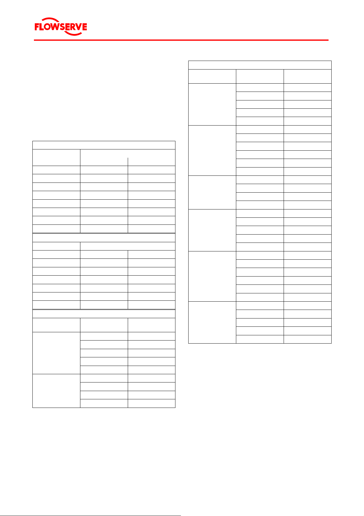
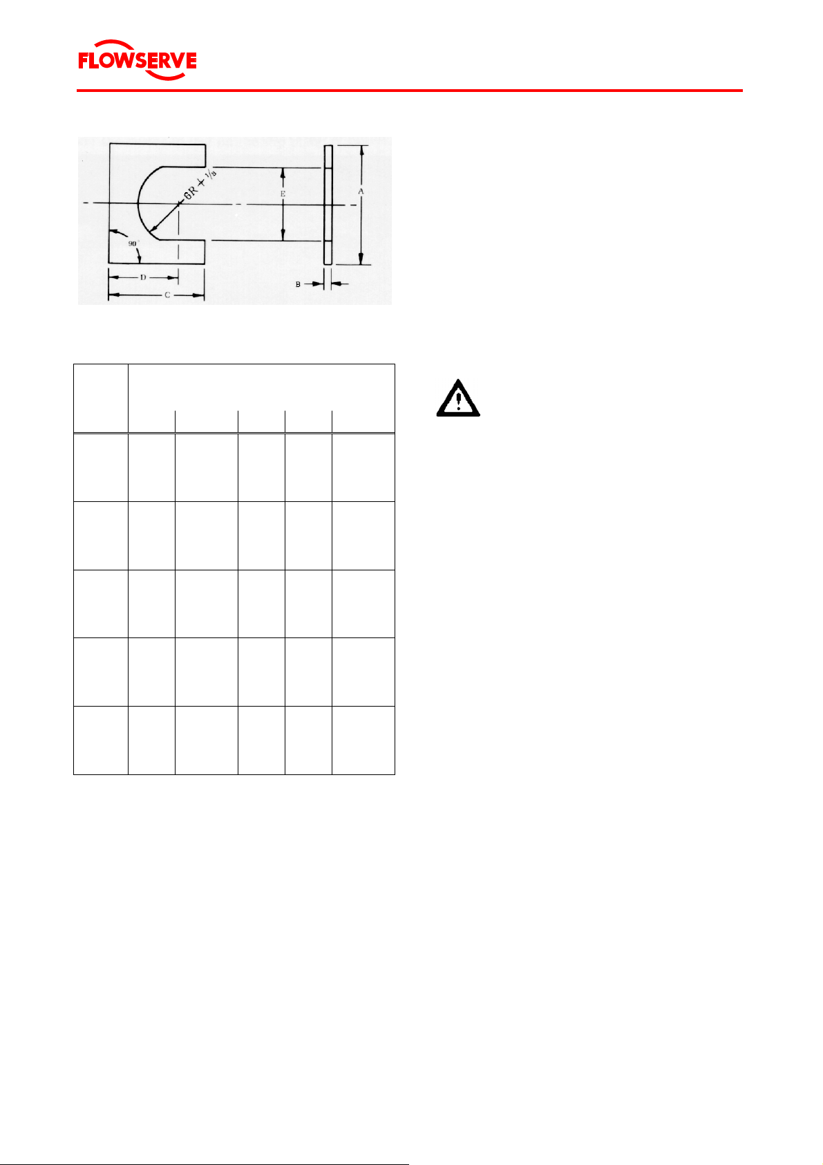
Figure 5 Motor U-plate
Nominal
motor
size
A B C D E
8" 38.10
10" 40.64
12" 45.72
14" 50.80
21" 91.44
Table 4 Motor U-plate chart
Dimensions in cm
(inches)
(15)
(16)
(18)
(20)
(36)
0.95 +
0.32
(0.375 +
0.125)
0.95 +
0.32
(0.375 +
0.125)
1.27 +
0.32
(0.500 +
0.125)
1.27 +
0.32
(0.500 +
0.125)
1.27 +
0.32
(0.500 +
0.125)
25.40
(10)
30.48
(12)
35.56
(14)
35.56
(14)
73.66
(29)
25.40
(10)
25.40
(10)
25.40
(10)
25.40
(10)
53.34
(21)
14.61 +
0.32
(5.750 +
0.125)
18.10 +
0.32
(7.125 +
0.125)
19.05 +
0.32
(7.500 +
0.125)
24.77 +
0.32
(9.750 +
0.125)
42.57 +
0.32
(16.760
+ 0.125)
4.2.3 Personnel required
Flowserve recommends that 2 persons plus 1
crane operator perform the installation or uninstallation procedure.
4.3 Hydraulic connection
Exemplary construction of a water supply system is
depicted in Figure 6, Page 22. As this shows a basic arrangement, the actual layout must be suited
to local and technical conditions.
DANGER
All work on the hydraulic connec-
tion may only be done by qualified
fitters.
Page 21 of 68
Page 22

®
Byron Jackson Double Mechanical Seal Submersible Pumping Unit • 1042.293/9 • June 04
Figure 6 Scheme of water supply system
Page 22 of 68
Page 23

®
f
Byron Jackson Double Mechanical Seal Submersible Pumping Unit • 1042.293/9 • June 04
4.4 Installation
4.4.1 Safety instructions
DANGER
Before starting any installation work
or removing any parts of the pumping unit, read Chapter 1.6 "Safety",
Page 6.
Tighten all screws in accordance
with Chapter 12.3 "Tightening
torques".
4.4.2 Sequence of installation
Perform the installation in the following order:
1. Prepare installation site, see Chapter 4.4.3,
Page 23.
2. Arrange components for installation, see
Chapter 4.4.4, Page 24.
3. Inspect components, see Chapter 4.4.5,
Page 25.
4. Install motor, see Chapter 4.4.6, Page 26.
5. Install coupling, see Chapter 4.4.7, Page 27.
6. Install pump bowl assembly, see Chapter 4.4.8, Page 30.
7. Install impeller, see Chapter 4.4.9, Page 32.
8. Vent motor, see Chapter 4.4.10, Page 33.
9. Install power cable, see Chapter 4.4.11,
Page 35.
10. Fasten the power cable to the cable guard,
see Chapter 4.4.12, Page 39.
11. Install riser pipe, fasten power cable to riser
pipe, see Chapter 4.4.13, Page 40.
12. Connect power cable to terminal box, see
Chapter 4.4.14, Page 43.
13. Connect terminal box to main power supply,
see Chapter 4.4.15, Page 43.
4.4.3 Prepare installation site
1. Verify that the wellhead foundation is poured
and cured, if made of concrete.
The total load on the wellhead foundation will
consist of the motor, pump bowl assembly,
riser pipe (full of water), wellhead assembly
and power cable. See Chapter 12.2 "Data
sheet", for weights.
2. Verify that open discharge run-off, ditch, etc.
for flushing out well and testing unit is provided for.
3. Verify that a log of the well recording depth,
straightness, casing variations, standing water
level, rated capacity, pumping level, etc., is at
the installation site.
4. Ensure that the well diameter is large enough
down to the installation depth so that the
pumping unit can be fitted without difficulties.
See Chapter 3.4.1 "Survey of well", Page 16.
5. Check the dependability of auxiliary equipment, particularly of hoists.
6. Compare the information in Chapter 12.2
"Data sheet" with that on the rating plate on
the motor.
7. Ensure that the line voltage (measured between two phases) is equal to the motor voltage according to the rating plate.
The maximum permissible voltage fluctuation
is given in Chapter 12.2 "Data sheet".
Greater voltage and frequency fluctuations
must be reported to Flowserve and be confirmed by Flowserve in written. In case of
doubt, ask Flowserve before starting up the
pumping unit.
8. Measure the insulating resistance of the motor
according to Chapter 6.8.1 "Insulation test",
Page 53.
CAUTION If the ascending riser pipe is made
of flanged pipes, the flanges must
have recesses for the power cable i
the well diameter is narrowly proportioned.
Page 23 of 68
Page 24

®
Byron Jackson Double Mechanical Seal Submersible Pumping Unit • 1042.293/9 • June 04
4.4.4 Arrange components fo r installation
Figure 7 Components arranged for installation
Refer to Figure 7. An orderly arrangement of subassemblies will reduce the installation time.
1. Lay out the parts in order of installation, as
follows:
• Motor
Arranged horizontally.
• Pump bowl assembly
Uncrated and arranged horizontally.
• Riser pipes
Place all riser pipe sections with coupling
end toward the well.
Check couplings with chain tongs to
make sure they are screwed tight.
Place riser pipe check valve sections so
that each will be installed in the proper
sequence.
• Power cable
• Wellhead
• Tools for installation, see Chapter 4.2
"Equipment and personnel required",
Page 19.
• U-plate
2. Record the complete motor serial number
from the motor, see Chapter 3.1.3 "Motor serial number", Page 14.
NOTE Make sure you can always quote each
part's serial number in correspondence and when ordering spare parts
or further accessories.
3. Check motor rating, horsepower, poles, volts,
and frequency against job requirements.
Page 24 of 68
Page 25

®
Byron Jackson Double Mechanical Seal Submersible Pumping Unit • 1042.293/9 • June 04
4.4.5 Inspect components
1. Remove the nuts (003-3) and lock washers
(690-3) to remove the motor terminal shipping
cap (112), and gasket (747-10).
2. Verify that motor terminal gland plate (111)
and power terminals (019) are clean and free
of dirt and foreign matter.
3. Megger the motor for ground and continuity
(see Figure 8).
The reading should be 10 MΩ or more.
Figure 8 Megger test
4. Remove the shipping cap from the power cable terminal box.
5. Verify that the terminal box and connectors
are clean and free of dirt and foreign matter.
6. Verify that the power terminals (019) at the
motor will fit the connectors of the terminal
box:
• Refer to Figure 9.
Check position of power terminals (019)
against that of connectors.
The terminals (019) and connectors may
be arranged in either an equilateral triangle or a right triangle positioning.
• Check height of terminal against depth of
connector to assure proper engagement.
Figure 9 Arrangement of terminals
7. Mount motor power terminal shipping cap
(112), gasket (747-10), lock washers (690-3)
and nuts (003-3).
8. Reinstall power cable shipping cap.
9. Verify that all riser pipe threads are clean and
free of dirt and foreign matter.
Page 25 of 68
Page 26

®
Byron Jackson Double Mechanical Seal Submersible Pumping Unit • 1042.293/9 • June 04
4.4.6 Install motor
Transport the motor to the well site, see Chapter
2.2.3 "Transport of the motor", Page 10.
Never step under floating load.
Watch for and avoid overhead ob-
structions including power lines.
1. Install motor U-plate on foundation.
Use to 2 persons to install the
U-plate.
Handle the U-plate carefully.
Danger of injury by dropping the
U-plate onto parts of the body.
2. Cover the U-plate and foundation with a tarpaulin.
3. Orient the motor horizontally so that the terminal shipping cap is on top.
Remove motor shipping cap (112-1), power
terminal gasket (744-6), nuts (003-8), and lock
washers (690-5). Some oil may be present in
the shipping cap.
Be certain to put the power terminal gasket
(744-6) in a safe area until it can be stored in
the motor shipping cap (112-1).
NOTE The power terminal gasket is not
used in the unit assembly.
Then remove the tools and the power terminal
gasket (744-10) from the power terminal shipping cap.
4. Reinstall motor shaft shipping cap (112-1),
nuts (003-8), and lock washers (690-5).
5. Lift the motor as described in Chapter 2.2.3
"Transport of the motor", Page 10.
6. Slowly elevate the motor to vertical position.
7. Center the motor over the well casing opening.
8. Lower the motor to rest on the U-plate.
Refer to Figure 10.
Figure 10 Motor in place on U-plate
9. Remove motor shipping cap (112-1), nuts
(003-8), and lock washers (690-5).
10. Cover coupling (529 or 531) and shaft with a
clean cloth.
The motor is now ready to receive the coupling.
Page 26 of 68
Page 27

®
Byron Jackson Double Mechanical Seal Submersible Pumping Unit • 1042.293/9 • June 04
4.4.7 Install coupling
NOTE Not all components or sub-
assemblies of a pumping unit are
neces
sarily supplied by Flowserve
or part of this delivery.
These user instructions apply only
to the c
omponen
ts or subassemblies supplied by Flowserve
in this delivery, see Chapter 12.1
"Scope of delivery".
The coupling between motor and pump bowl as-
nds on the type of pump bowl assem-
sembly de
pe
bly delivered.
Flowserve manufactures two coupling variants for
the Byron Ja
ckson Doubl
• Variant A: Motor half coup
• Variant B: One-pie
e Mechanical Seal Motor:
ling
ce coupling
Both are described in the following. See Chapter
12.1 "Sco
of delivery" to determine the coupling
pe
delivered and follow the respective instructions.
Variant A: Motor half coupling
1. Motor half coupling is factory installed. Refer
to Figure 11
.
washers (690-4), shaft button screw (806-2)
and shims (262-6 and 262-7).
7. Remove string from shaft button screw
) which holds shim in place.
(806-2
Verify that the shims (262-6 and 262-7) are
attach
ed to the screw (806-2).
8. Install alignment jig assembly in motor half
pling (265
cou
).
9. Install cap screw (806-2) and use wrench pro-
vided to tighten screw (80
6-2).
10. Remove the coupling lock screws (806-3) and
a
shers (690-4).
w
Set these pieces aside for later use (see
p
ter 4.4.8 "Install pump bowl assembly",
Cha
Page 30).
11. Remove alignment jig (265) and hold for stor-
ping cap (112-1).
age in moto
r ship
12. Clean the motor flange face of any dirt or for-
eign matter.
Verify that the balance line hole in the flange
pen
face is o
and clear.
13. Cover the coupling (529) and shaft with a
n cloth.
clea
The m
otor is now ready to receive the pump bowl
assembly.
2. Clean coupling and shaft, and lightly oil both.
3. Slip coupling on shaft with keyways aligned.
NOTE Do not attempt to force the cou-
pling.
If the coupling will not seat freely:
- remove the coupling
- verify that the shaft is free of dirt
and foreign matte
r
- replace the coupling.
4. Insert key (676-1), round end down, in the
key
w
ay.
5. Install socket head set screw (806-1) through
in th
its hole
e coupling (529) to engage its
hole in the shaft.
Use wrench provided to tighten set screw
).
-1
(806
6. Identify the shaft adjusting button (130),
alignmen
t jig (265), screws (806-3) with
Page 27 of 68
Page 28

®
Byron Jackson Double Mechanical Seal Submersible Pumping Unit • 1042.293/9 • June 04
Figure 11 Motor half coupling components
Page 28 of 68
Page 29

®
Byron Jackson Double Mechanical Seal Submersible Pumping Unit • 1042.293/9 • June 04
Variant B: One-piece coupling
See Figure 12.
1. Clean the coupling (531) and shaft and lightly
oil both.
2. Identify the thrust button (130), thrust button
screw (806-2) and shaft adjusting shims
(262-6 and 262-7) as required. These pieces
are factory installed.
3. Insert key (676-1), round end down, in the
keyway.
4. Slip coupling (531) on shaft with keyways
aligned.
CAUTION Do not force the coupling.
If the coupling will not seat properly, again verify that shaft and
coupling are clean.
5. Install the coupling pins (697) into the coupling holes and the thrust button.
The thrust button may need to be rotated to
align holes.
Install the coupling lock screws (806-6), flat
washers (004-1), a nd lock washers (6 90-6) to
secure the pins in the coupling.
6. Tighten the thrust button socket head screw
(806-2).
7. Rotate the motor shaft and coupling until the
pin holes on the coupling are pointed 90 °
from the power terminal shipping cap.
This aligns pin holes in coupling with adapter
bracket to allow pump coupling pin (697-1) to
be installed later. Also see Figure 12.
8. Clean the motor flange face of any dirt or foreign matter. Verify that the balance line hole is
open and clear.
9. Cover the coupling (531) and shaft with a
clean cloth.
Figure 12 Components for one-piece coupling
The coupling is now ready to receive the pump
bowl assembly.
Page 29 of 68
Page 30

®
Byron Jackson Double Mechanical Seal Submersible Pumping Unit • 1042.293/9 • June 04
4.4.8 Install pump bo wl assembly
NOTE Not all components or sub-
assemblies of a pumping unit are
necessarily supplied by Flowserve
or part of this delivery.
These user instructions apply only
to the components or subassemblies supplied by Flowserve
in this delivery, see Chapter 12.1
"Scope of delivery".
Lift pump bowl assembly
Never step under floating load.
Watch for and avoid overhead ob-
structions including power lines.
NOTE The following description refers to
pumps without auxiliary carriers.
The motor hangs in the well on the U-plate.
1. Disassemble discharge housing or non-return
valve from the pump bowl assembly.
2. Install the discharge housing or non-return
valve in the short section of riser pipe.
Additional information for threaded riser pipes:
a. Clean the mating pipe threads of the pipe
and the case or flange as shown in
Figure 13.
Should the pump be delivered on an
auxiliary carrier, refer to the pump
manual for lifting instructions.
To transport the pump bowl assembly to the well
site see Chapter 2.2.4 "Transport of the pump bowl
assembly", Page 11.
1. Connect the pump to two lifting lines of a
portable crane.
The attachment points may vary according to
pump type and local requirements.
2. Carefully lift the pump to a vertical position
over the well head.
Install pump bowl assembly
The riser pipes are connected among each other
by
• threads or
• flanges.
Figure 13 Cleaning riser pipe threads
b. Apply thread locking fluid, e. g. Loctite
242 or DELO 5249/5349 or equivalent, to
the threads as shown in Figure 14.
Figure 14 Applying thread locking fluid
Page 30 of 68
Page 31

®
r
Byron Jackson Double Mechanical Seal Submersible Pumping Unit • 1042.293/9 • June 04
c. Install the pipe using chain tongs.
Figure 15 shows the proper method of
applying chain tongs to the flange.
Thereby most of the force is exerted on
the upper flange rather than the on the
discharge housing or the non-return
valve.
Apply torque approximating the values
given in Table 5.
CAUTION The discharge section may require
modification to provide protective
clearance to the flat cable and
splice which will be mounted late
on the riser pipe just above the
pump.
3. Mount the first length of the riser pipe, which
should not be longer than 0.5 m, onto the assembled pump bowl assembly.
4. Remove the cable clamps or cable guard from
the pump bowl assembly.
5. Remove the cloth from the coupling.
6. Lift the pump bowl assembly above the motor.
7. Check the end float settings that are preadjusted by Flowserve.
Figure 15 Proper method of applying chain tongs
Pipe Torque Torque
Size [Nm] [ft-lbs]
2-1/2 620 500
3 950 700
4 1 220 900
5 1 425 1 050
6 1 625 1 200
8 2 170 1 600
10 2 710 2 000
12 4 070 3 000
Table 5 Torque for riser pipe assembly
Page 31 of 68
Page 32

®
Byron Jackson Double Mechanical Seal Submersible Pumping Unit • 1042.293/9 • June 04
4.4.9 Install impeller
NOTE Not all components or sub-
assemblies of a pumping unit are
necessarily supplied by Flowserve
or part of this delivery.
These user instructions apply only
to the components or subassemblies supplied by Flowserve
in this delivery, see Chapter 12.1
"Scope of delivery".
Flowserve manufactures two impeller variants for
the Byron Jackson Double Mechanical Seal Motor:
Figure 16 Verify end float
• Variant A: Closed impeller
• Variant B: Open impeller
Both are described in the following. See Chapter
12.1 "Scope of delivery" to determine the coupling
delivered and follow the respective instructions.
Variant A: Closed impeller
1. Refer to Figure 16.
Scale from the face of the adapter bracket
(808) to the end of the pump shaft (167) with
the shaft down.
2. Remove adapter bracket (808) from bowl assembly.
3. Install adapter bracket (808) on motor top
flange, using fasteners for motor shipping cap
(112-1).
4. Scale from the face of the motor top case
(076) to the face of the shaft adjusting button
(130).
5. The distance recorded in step 1 should be
3.175 mm to 6.350 mm (1/8" to 1/4") less than
that of step 4.
Variant B: Open impeller
1. Remove adapter bracket (808) from bowl assembly.
2. Install adapter bracket (808) on motor top
flange, using fasteners from motor shipping
cap (112-1).
3. Remove the pump half coupling (530) or onepiece coupling (531).
4. Provide four pieces of shim stock, each
(50.8 mm x 50.8 mm x 0.508 mm (2" x 2" x
0.020") thick, and place each shim 90 degrees
apart on the face of the adapter bracket.
5. Lower the pump bowl assembly into the
adapter bracket (808) to rest on the shims.
6. Put a feeler gauge through the plug opening
in the adapter bracket (808) and check the
gap from shaft adjusting button (130) to pump
shaft (167).
7. If gap, step 6, is less than 0.0381 mm (0.015")
or more than 0.4572 mm (0.018"), the shims
beneath the shaft button (130) must be
changed.
8. Reinstall the pump half coupling (530) or onepiece coupling (531).
Page 32 of 68
Page 33

®
r
Byron Jackson Double Mechanical Seal Submersible Pumping Unit • 1042.293/9 • June 04
4.4.10 Vent motor
1. Remove the oil vent plugs (806-4) and (806-5)
in the flange located at the power terminals
and 90° or 180° from the power terminals.
Add oil into the adapter bracket as shown in
Figure 17. See Chapter 12.2 "Data sheet",
Page 65, for oil quality.
NOTE Do not add more than two full moto
shipping caps' amount of oil during
the venting process. The oil level in
the motor will then rise and expel
any air in the upper case cavity.
Figure 18 Removing vent plug
Figure 17 Adding oil
2. Continue to add oil until bubble free oil flows
from the vent located near the power terminals.
Reinstall vent plug (806-4). Refer to Figure
18.
Continue to add oil until bubble free oil flows
from the vent located 90° or 180° from the
power terminals.
Reinstall vent plug (806-5) and tighten to
27 Nm (20 foot pounds). Refer to Figure 18.
Figure 19 Reinstalling vent plug
3. Remove oil vent plug next to power terminals
(806-4) and again check for bubble free oil.
Reinstall vent plug (806-4) and tighten to
27 Nm (20 foot pounds).
4. Place power terminal shipping cap (112-2),
power terminal gasket (744-7), jig (265), hex
socket wrenches (806-1, 806-2, 806-4, and
806-5), and power terminal gasket (744-6)
into the motor shipping cap (112-1).
Send to storage.
The motor is now ready to receive the pump
bowl assembly.
6. Verify that the pump half coupling (530) or
one-piece coupling (531) is securely locked in
place
- by the coupling pin (697-1) and retainer
ring (526) on pump half coupling or
Page 33 of 68
Page 34

®
Byron Jackson Double Mechanical Seal Submersible Pumping Unit • 1042.293/9 • June 04
- by the coupling pin (697-1) and the retainer
screws (806-6), flat washers (004-1), and
lock washers (690-5) on the one-piece
coupling.
Also verify that the coupling bore and motor
shaft are clean and free of dirt and foreign
matter.
7. Refer to Figure 20.
Lower the bowl assembly to engage
- the jaws of the pump half coupling (530)
and those of the motor half coupling (529)
or
- the one-piece coupling bore (531) with the
motor shaft and key (676-1).
9. Remove the adapter bracket pipe plugs (794)
to observe, through the pipe plug holes, the
alignment of the holes for the half coupling
lock screws (806-3).
Install the half coupling lock screws (806-3) in
the half-coupling, with their washers (690-4)
and apply torque to the half coupling screws
(806-3) according to Table 6.
Unit size
[inches]
8 27 20
10 41 30
12 54 40
14 54 40
17 68 50
18 68 50
21 68 50
Table 6 Torque for half coupling screws
Torque
[Nm]
Torque
[Ft-lbs]
Figure 20 Aligning strainer and adapter
8. Rotate the bowl assembly to line up bolt holes
of strainer with those of the adapter (808) and
to line up bottom cable guard with power terminal shipping cap (112-2), then lower until
flanges butt metal-to-metal.
Install and tighten fasteners (cap screws or
stud nuts with washers).
After tightening, check that lock washers
(806-3) are seated firmly and lock washers
(690-4) are compressed.
For one piece couplings, you will now install
the coupling pin (697), coupling lock screws
(806-6), lock washers (690-6), and flat washers (004-1) or the retaining rings (526) to retain the coupling pin in its proper position.
10. Reinstall the adapter bracket pipe plugs (609)
and tighten firmly.
11. The strainer body has two holes, size 1/8"
N.P.T. at 180°. Pour water into one of these
holes to fill the adapter bracket (808) until water runs out the other hole. (A 90° street elbow
is used for this purpose.)
The pumping unit is now ready for installation of
the power cable.
Page 34 of 68
Page 35

®
Byron Jackson Double Mechanical Seal Submersible Pumping Unit • 1042.293/9 • June 04
4.4.11 Install power cable
NOTE Not all components or sub-
assemblies of a pumping unit are
necessarily supplied by Flowserve
or part of this delivery.
These user instructions apply only
to the c
omponen
ts or subassemblies supplied by Flowserve
in this delivery, see Chapter 12.1
"Scope of delivery".
• Use a
rope to hold the cable and the power
e installation wheel to support the power
cabl
cable.
• Bring the p
ower cable looping up off the
power cable reel stand so that the power cable terminal box is suspended over the power
terminal shipping cap.
CAUTION Do not strain the power cable or
t
bend i
sharper than a diameter of
14 times the power cable outer diameter.
Avoid strain on terminal box.
Do not use cable installation wheel
pend
to sus
cable above the top of
pump bowl assembly until the flat
cable guards are securely banded.
In the following, two variants of the power cable
scri
are de
bed:
• Power cable for voltages of 2 300 V and less
(metal cl
amp power terminal connector)
• Power cable for voltages of 4 000 V and
greate
r (metal housing power terminal con-
nector)
Page 35 of 68
Page 36

®
r
Byron Jackson Double Mechanical Seal Submersible Pumping Unit • 1042.293/9 • June 04
Power cable for voltages of 2 300 V and less
(metal clamp power terminal connector)
1. Use the power cable installation wheel to unreel a sufficient length of power cable to pass
the bowl assembly.
Elevate the power cable to the approximate
height of the pump bowl assembly and fasten
the cable plug to the motor.
CAUTION Do not kink or stretch the powe
cable.
2. Remove the power terminal shipping cap nuts
(003-3), washers (690-3) and power terminal
shipping cap (112) at the motor.
3. Depending on configuration supplied:
• For flat faced (no rabbet fit) gland plate:
Install flat gasket (744-10) over power
terminals (019).
See Figure 21.
4. Remove the shipping cap (023) from the
power cable plug (182).
5. Refer to Figure 22.
Slide the metal terminal box clamp (180)
down over the terminal box (182) as far as
possible.
Then check gap from bottom face of terminal
box clamp (180) to bottom face of terminal
box. This gap should be minimum 0.8 mm
(1/32) and maximum 2.4 mm (3/32).
Figure 22 Checking gap, terminal box clamp to terminal
box
Figure 21 Installing power terminal gasket (flat-faced
type shown)
• For gland plate with rabbet fit:
First install gasket (744-11) over rabbet
fit on gland plate (111).
Then install gasket (744-10) over the mo-
tor terminals (019).
6. See Figure 23.
Slide the metal clamp (180) up the flat cable
and off the cable plug (182), loosening the
clamping screws (806), if necessary.
CAUTION Do not distort the clamp.
Figure 23 Preparing terminal box clamps
Page 36 of 68
Page 37

®
Byron Jackson Double Mechanical Seal Submersible Pumping Unit • 1042.293/9 • June 04
7. See Figure 24.
Align plug connectors with the motor power
terminals and push the cable plug (182) down
on the motor power terminals (019) to mate
with the gland plate (111) and gasket(s)
(744-10, 744-11).
Figure 24 Terminal box installed
8. See Figure 25.
Slide metal clamp (180) down over terminal
box (182) and gland plate studs (002-1)
9. Install washers (690-3) and nuts (003-3).
Tighten the nuts (003-3) alternatively and
evenly to bring the clamp (180) firmly metal to
metal against the gland plate (111).
Figure 25 Power cable clamp installed
10. Back off the nuts (003-3) two or three turns
each and tighten clamping screws (806).
11. Retighten the nuts (003-3) to achieve metalto-metal fit of clamp (180) to gland plate (111).
12. Attach ground wire to rib of pump adapter using terminal, lock washer and cap screw.
13. Using surface end of the power cable, which
should be accessible, megger the power cable and motor for ground and continuity.
The megger reading should 10 MΩ or more.
14. When megger test is completed, install a plastic bag over the surface end of the power cable for protection from the weather.
Continue with "Fasten the power cable to the cable
guard", Page 39.
NOTE Key and keyway must be engaged
prior to terminal engagement to prevent damage.
Page 37 of 68
The gland nut must be tightened by
hand and repeated until seal is accomplished.
Failure to fully engage the plug and
receptacle will result in electrical
failure.
Page 38

®
Byron Jackson Double Mechanical Seal Submersible Pumping Unit • 1042.293/9 • June 04
Power cable for voltages of 4 000 V and greater
(metal housing power terminal connector)
Figure 26 Metal housing power terminal connector
(4 000 V-cable)
1. Remove the power terminal shipping cap nuts
(003-3), washers (690-3) and power terminal
shipping cap (112) at the motor.
2. Remove the shipping cap (023) from the
power cable connector (182).
Place new O-Ring (747-10) into groove of the
terminal gland plate (111) at the motor top
case (074).
4. Align the power cable connector (182) with
the motor power terminals (019) and push
down them down to mate with the gland plate
(111) and O-Ring (747-10).
Slight side-to-side movement will aid this en-
gagement.
3. Install the lock washers (690-3) and tighten
nuts (003-3) at gland plate studs (002-1).
4. Tighten the nuts alternately and evenly to
bring the power cable connector (182) firmly
metal to metal against the gland plate (111) at
the motor top case (074).
5. Attach ground wire to rib of pump adapter using terminal, lock washer and cap screw.
6. Using surface end of the power cable, which
should be accessible, megger the power cable and motor for ground and continuity. The
megger reading should 10 MΩ or more.
7. When megger test is completed, install a plastic bag over the surface end of the power cable for protection from the weather.
Continue with "Fasten the power cable to the cable
guard", Page 39.
NOTE Key and keyway must be engaged
prior to terminal engagement to prevent damage.
The gland nut must be tightened by
hand and repeated until seal is accomplished.
Figure 27 O-ring for metal housing power terminal
connector at motor gland plate (4 000 V-cable)
3. Refer to Figure 27.
Failure to fully engage the plug and
receptacle will result in electrical
failure.
Page 38 of 68
Page 39

®
Byron Jackson Double Mechanical Seal Submersible Pumping Unit • 1042.293/9 • June 04
4.4.12 Fasten the power cable to the cable
guard
4. Remove the U-plate.
Use to 2 persons to remove the
U-plate.
Handle the U-plate carefully.
Danger of injury by dropping the
U-plate onto parts of the body.
5. Install a clamp to hold the pumping unit.
The pumping unit is now ready for the attachment
of riser pipe and lowering into the well.
Figure 28 Outer guard and band in place - example
1. Inspect cable guards, particularly their inner
surfaces, for sharp edges that could damage
the cable jacket or insulation.
2. Support the cable alongside the pump bowl
assembly with the cable installation wheel
without stretching or straining the terminal
box.
CAUTION The attachment of the power cable
to the cable guard depends on the
type of the pump bowl assembly.
3. Slightly lift the pumping unit.
Page 39 of 68
Page 40

®
Byron Jackson Double Mechanical Seal Submersible Pumping Unit • 1042.293/9 • June 04
4.4.13 Install riser pipe, fasten power cable to
riser pipe
NOTE Not all components or sub-
assemblies of a pumping unit are
necessarily supplied by Flowserve
or part of this delivery.
These user instructions apply only
to the c
omponen
ts or subassemblies supplied by Flowserve
in this delivery, see Chapter 12.1
"Scope of delivery".
CAUTION Do not stretch the power cable and
the splices.
During the installation, observe the following pre-
ns:
cautio
• Support the
pumping unit weight with riser
pipe elevator.
• Keep the riser pip
e centered in the well cas-
ing.
• While lowe
ring the riser pipe, hold the power
cable flat against the pipe and keep it from
dragging across the sharp well casing or
flange.
• Avoid loss of power cable l
• Prevent rotation of the riser pi
ength.
pe so that the
power cable does not spiral wrap around it.
• If used or out of round ri
ser pipe is utilized it is
recommended to weld a steel strap across
each coupling to prevent unthreading during
start up or running.
Install the riser pipe(s)
1. Raise power cable installation wheel to 1.5
times the riser pip
e length to facilitate power
cable alignment to riser pipe and well casing.
2. Arrange the random lengths of riser pipe with
g ends facing one direction.
their co
uplin
At five feet in from each pipe end, draw a
chalk ma
rk to set the banding location.
3. Install the riser pipe.
Ensure that the flow direction is upward.
If the riser pipes are threaded:
• Clea
n the mating pipe threads of the riser
s shown in Figure 13, Page 30.
pipe a
• Apply thread
locking fluid, e. g. Loctite
242 or DELO 5249/5349 or equivalent, to
the threads as shown in Figure 14,
Page 30.
• Install the pipe usi
Figure 15, Page 31) and apply torque ac-
ng chain tongs (see
cording to Table 5, Page 31.
6. When the motor first enters the water, use the
e end of the power cable to megger the
c
surfa
power cable and motor for ground and continuity. The reading should be 10 MΩ or more.
If one or more vertical riser pipe check valves are
d
to be use
on an installation, each valve, which
should have a bleed-back self draining feature, will
take the place of a riser pipe coupling.
The recommended installation is as follows:
• One valve:
Locate the valve approximately 23 m (75 feet)
above the pu
mp bowl a
ssembly.
• Two valves:
Locate the first valve 30 m (100 feet) above
the pump bowl assem
bly.
Locate the second valve at 3/5 of the distance
en fi
betwe
rst valve and the surface support
plate.
Fasten the power cable to the riser pipe
Use "BAND-IT" or equal stainless steel bands and
buckles
to fasten the cable guard to the riser pipe.
Pull each steel band tight enough to fasten the ca-
ard
ble gu
onto the riser pipe, but do not over ten-
sion it.
Instructions for use of "BAND-IT" materials and
e shown in Figure 29, Page 41, to Figure
tools a
r
36, Page 42.
Page 40 of 68
Page 41

®
Byron Jackson Double Mechanical Seal Submersible Pumping Unit • 1042.293/9 • June 04
Use of BAND-IT steel bands
1. Cut off about 12" of band from the bulk roll.
Figure 29 Use of "Band-It" steel band, step 1
2. Hook one end on the buckle and bring the
other end around the object to be banded and
through the buckle.
For best results, apply the band twice around.
Double banding develops almost 4 times the
grip of single banding.
3. Draw band tight.
With the thumb on the band gripper lever, ap-
ply tension with the tool.
Figure 31 Use of "Band-It" steel band, step 3
4. Apply a proper amount of tension. The band
gripper lever locks itself under tension.
Figure 30 Use of "Band-It" steel band, step 2
Figure 32 Use of "Band-It" steel band, step 4
Page 41 of 68
Page 42

®
Byron Jackson Double Mechanical Seal Submersible Pumping Unit • 1042.293/9 • June 04
5. Rotate the tool over the buckle, backing of
with tension handle throughout the entire
course of the bend.
Failure to back off with tension handle
throughout the entire course of bend may result in breaking of band. There is no loss of
tension, as the band released is used up in
the bend.
Figure 33 Use of "Band-It" steel band, step 5
7. Remove the tool holding the stub of the band
down with your thumb.
Figure 35 Use of "Band-It" steel band, step 7
8. Lock the stub by hammering down the buckle
ears, thus completing the BAND-IT clamp.
6. Pull the cutter handle to cut the band.
Figure 34 Use of "Band-It" steel band, step 6
Figure 36 Use of "Band-It" steel band, step 8
Page 42 of 68
Page 43

®
Byron Jackson Double Mechanical Seal Submersible Pumping Unit • 1042.293/9 • June 04
4.4.14 Connect power cable to terminal box
NOTE Not all components or sub-
assemblies of a pumping unit are
necessarily supplied by Flowserve
or part of this delivery.
These user instructions apply only
to the components or subassemblies supplied by Flowserve
in this delivery, see Chapter 12.1
"Scope of delivery".
DANGER
Before completing the electrical con-
nection, review Chapter 3.5
"Electrical requirements", Page 17.
The surface plate assembly is screwed in place
and the pumping unit hangs well above the well
base.
1. Measure and cut the cable to approximate
length for surface make up.
2. Strip the power cable, if necessary.
3. Feed the cable through the packing gland (or
glands) in wellhead and then into the terminal
box.
4. Connect the terminal box leads to the power
cable.
Each lead is to be waterproof.
5. Place the two final supporting cable clamp
assemblies 0.9 m to 1.2 m (3 feet to 4 feet)
below the wellhead.
6. If the power cable is a 4-conductor cable and
the grounding is in the scope of delivery:
make the ground wire connection to wellhead
with lug, lock washer and cap screw.
7. Lower the wellhead into its correct position
and secure it in place.
8. At the terminal box, megger the power cable
and motor for ground and continuity.
The reading should be 10 MΩ or more.
The pumping unit is now ready for connection to
the power supply.
4.4.15 Connect terminal box to main power
supply
NOTE Starting equipment for the pump
bowl assembly is furnished by the
customer.
1. Ensure that the rating of the equipment is
used conform to the National Electric Code
requirements for high reactance squirrel cage
motors.
Make certain that the starter main contacts
are in good condition and are working properly.
Also see that the overload relays are for the
correct full load current.
To ensure that the starter is operated safely,
verify that the panel housing is properly
grounded to a ground rod and to the surface
plate assembly.
2. Check the no-load voltage at the starter be-
tween all three phases. The voltage values
must be equal and must be approximately the
same as the voltage rating.
3. Strip back the outer sheath on the cable be-
tween 152 mm and 457 mm (6 " to 18") depending on cable size and panel terminal requirements.
Strip by scoring the sheath, lengthwise with a
knife or tool to the length needed, in several
places around the outside.
Do not cut all the way through and damage
the individual conductor insulation.
Grasp a scored segment of the sheath at the
end and peel like a banana.
Repeat this all the way around and cut off the
stripped segments.
4. Strip a short segment of insulation off the end
of each conductor for connection into the
starter load terminals.
5. Remove a conduit knock-out in the bottom of
the panel. Install the cable with its gasketed
grip in this hole, and connect to the starter
load terminals.
6. Ensure that the starter cannot be activated
accidentally.
7. Perform insulation test as described in Chap-
ter 6.8.1 "Insulation test", Page 53.
Insulation resistance must be at least 10 MΩ.
Page 43 of 68
Page 44

®
Byron Jackson Double Mechanical Seal Submersible Pumping Unit • 1042.293/9 • June 04
8. Perform continuity test as described in Chapter 6.8.2 "Continuity testing, Page 53.
9. Connect the terminal box to the power source
cable.
The pum
ping unit is now ready to be started.
Page 44 of 68
Page 45

®
Byron Jackson Double Mechanical Seal Submersible Pumping Unit • 1042.293/9 • June 04
4.5 Uninstallation
4.5.1 Safety instructions
DANGER
Before starting any installation work
or removing any parts of the pumping unit, read Chapter 1.6 "Safety",
Page 6.
Tighten all screws in accordance
with Chapter 12.3 "Tightening
torques".
DANGER
If the area was designated a hazard-
ous location, refer to applicable
safety procedures for safe handling
of tools, equipment, and test instruments.
CAUTION If the pumping unit is equipped with
a non-return valve without load relieving holes, the pumping unit
weight with ascending pipeline und
the water column contained within it
must be lifted during removal!
If the non-return valve is provided
with load relieving hoIes, the weight
of the water column does not apply.
4.5.2 Uninstallation
1. Stop the pumping unit operation at the control
panel.
2. Measure the power cable leads to check insulation resistance (leads-to-ground) and conductance (lead-to-lead) as directed in Chapter 6.8 "Electrical tests of the motor", Page 53.
b. Disconnect power cable form terminal
box, see Page 43.
c. Uninstall riser pipe and detach power ca-
ble from riser pipe, see Page 40.
If the bands are double wrapped, cut
them properly so that they can be saved
for use as a single band for reinstallation.
d. Uninstall power cable, see Page 35.
Separate cable from motor and seal the
cable with the original terminal box ship-
ping cover (023).
e. Uninstall pump bowl assembly, see
Page 30.
f. Uninstall coupling, see Page 27.
g. Uninstall motor, see Page 26.
5. Check the riser pipes for need of replacement,
particularly the sections between high and low
well fluid levels.
6. Inspect any column check valves for wear and
proper functioning.
7. Remove the coupling retainer rings, retainer
screws, lock washers, and coupling pins.
Separate the pump element from the motor
between the adapter bracket (808) and the
strainer body (564).
8. Megger the motor for ground and continuity.
Reading should be 10 MΩ or more.
9. Seal the motor terminals with original power
terminal gasket (744-7) and power terminal
shipping cap (112-2).
10. If there is water in the motor, elevate motor
over a sump or drum. Remove lower casing
drain plug (806) from bottom of motor, then
remove vent plugs (806-4 and 806-5) at top of
motor to drain the water from the motor. Replace drain and vent plugs.
Continue with Chapter 2.3 "Storage and shipping",
Page 12.
3. Disconnect the cable at the starter panel.
Megger the leads for ground and continuity.
Reading should be 10 MΩ.
4. Remove the pumping unit in the reverse order
of the installation procedure (see Chapter 4.4
"Installation", Page 23) and place all parts on
the floor.
Also consider Chapter 2.2 "Transport",
Page 10.
a. Disconnect terminal box from main power
supply, see Page 43.
Page 45 of 68
Page 46

®
r
Byron Jackson Double Mechanical Seal Submersible Pumping Unit • 1042.293/9 • June 04
5 COMMISSIONING STARTUP, OP-
ERATION AND SHUTDOWN
5.1 Safety instructions
NOTE Before commissioning, operation o
shutdown of the pumping unit, read
Chapter 1.6 "Safety", Page 6.
The pumping unit may only be operated
• by trained pe
• in a comple
• completely filled and immersed.
nel,
rson
tely assembled condition, and
5.2 Direction of rotation
The direction of rotation of motor and pump is
given in Chapter 12.2 "Data sheet".
5.3 Starting the pump
5.3.1 First-time start-up of the pump
1. Measure insulation resistance (leads-toground
turned off to ascertain that not short circuits
are present.
CAUTION Do not attempt to start the pumping
2. Verify that balanced three-phase voltage is
sup
meter and using the voltmeter selector switch.
CAUTION Never attempt to run the pumping
) with power turned off and motor
w
unit
reading of less than 5 MΩ.
p
lied by taking readings with the line volt-
unit
tween two leads.
An imbalance between two leads
can cau
of imbalance in an amperage and the
resultant temperature increase
means a decrease in motor life.
Poor voltage regulation of an engine
driv
tained from such a source, can be
very detrimental.
ith an insulation resistance
w
ith an unbalanced voltage be-
se 6
- 10 times that amount
en gener
ator, if the power is ob-
3. Close the pump discharge valve.
4. Start the motor.
The contractor closes and the pump motor
s.
art
st
CAUTION Do not run the pump for more than
minutes
2
closed.
5. Immediately take current reading using line
ammeter.
If the current is in the range of amps at shut-
off (see
correct.
If current is about 80 % of shut-off amps, rota-
tion is
a. press STOP
b. turn off all power
c. move isolator handle to OFF
d. reconnect motor leads for proper rotation.
Mark the leads so that they can always be
placed corre
6. After verifying proper rotation,
• stop the pum
• open the discharg
• start the pumping unit ag
7. Recheck the current, which should be the full
load cu
sheet".
Current could also be the same as full load
amps with re
would be greatly reduced.
CAUTION If a circuit breaker trips, always wait
During first-time start-up, take notice of the following:
• Whe
spe
If after this period the line current is still high
(over twi
not attaining the full speed.
Chapter 12.2 "Data sheet"), rotation is
orrect. In this case,
not c
c
nt as shown in Chapter 12.2 "Data
rre
verse
at leas
n motor is started, it should attain full
ed within 3 seconds.
c
e normal value), the pumping unit is
with discharge valve
tly any time they are removed.
ping unit.
e valve
ain.
d rotation but head and flow
t 10 minutes be
fore resetting.
Page 46 of 68
Page 47

®
Byron Jackson Double Mechanical Seal Submersible Pumping Unit • 1042.293/9 • June 04
CAUTION In the event the pumping unit does
not attain the full speed, stop the
pumping unit and do not attempt to
restart it until the trouble is found
and corrected.
During normal operation, the current must not ex-
the motor data plate value.
d
cee
• Measure the line voltag
e between phases
while the pumping unit is pumping.
The readings obtained should not be more
than 10 % a
bove or below the rated motor
voltage.
• In case of malfunction, stop the pumping unit
and refe
r to Chapter 7 "Faults, causes and
remedies", Page 56.
5.3.2 Normal start-up of the pump
CAUTION If maintenance has been performed,
w
Chapter 5.3.1 "First-time start-
follo
up of the pump", Page 46.
1. Verify that the control panel door is closed.
2. Verify that balanced three-phase voltage is
lied by taking readings with the line volt-
supp
meter and using the voltmeter selector switch.
CAUTION Never attempt to run the pumping
w
unit
ith an unbalanced voltage be-
tween two leads.
then stop the pumping unit and refer to Chap-
ter 7 "Faults, cau
ses and remedies", Page 56.
5.4 Running or operation
5.4.1 Performance and operating limits
Usually, a pumping unit has been selected and
built to perform a maximum efficiency under de
fined conditions, see Chapter 3.3 "Performance
and operating limits", Page 15.
crease or de-
Changes of these conditions, e.
g. in
crease in head, will not cause an noticeable difference in the efficiency.
However, a large variation in head will not only
up as efficiency loss, but as a output, or
show
thrust bearing overload.
Water level
• A well shou
ld alway
s be provided with a
means for determining the static water level,
and pumping level. A good air line, with depth
gage, is generally the most simple and practical.
rin
• For monito
g the water level in the well, we
recommend water level detectors or water
level measuring units.
Sand
• When a pumping unit is first started, a new
well may produ
ce considerable amounts of
sand, despite the fact it had been sand
pumped after drilling.
-
3. Start the pumping unit.
The contractor completes the pump circuit,
and the pump
motor starts.
4. Verify that the pump motor comes up to speed
3
within
seconds as indicated by normal read-
ings of current, voltage, head and flow.
If
• current exceeds the rated value of the
ampe
rage shown in Chapter 12.2 "Data
sheet", or
• voltage varie
s + 10 % or - 10 % from the
rated value shown in Chapter 12.2 "Data
sheet", or
• head and flo
w are abnormal
Page 47 of 68
The discharge should be throttled back to
e this is cut down to a minimum, then
r
whe
gradually opened up to full discharge as the
sand disappears.
This operation may last from a matter of minutes to seve
ral days or lo
nger.
If the sand flow shows no signs of stopping
• rework the well to screen
• install a pumping unit
out the san
with a capacity
d, or
smaller than that of the currently installed
unit.
Continued sand pumping will result in in-
p wear which in turn will show up
creased
pum
as increased efficiency loss. Too great a wear
will run the pump beyond the repair stage and
possibly have serious effects on the motor.
Page 48

®
r
Byron Jackson Double Mechanical Seal Submersible Pumping Unit • 1042.293/9 • June 04
• Some wells will always produce a small
amount of sand at start-up. Therefore, it may
be necessary to bypass or trap out this first
flow at each start-up, particularly if a closed
piping system is used.
• Whe
n a pumping unit is known installed near
to the bottom of a well, a
close check should
be kept to make sure that the well does not
sand-up (fill in) around the motor.
This is may take place without any noticeable
mping or motor operation. How-
effect in
pu
ever, the motor is dependent on adequate
cooling from water, and any sand around it
would eventually create overheating, resulting
in at least shortened life, if not a burnout.
If this problem cannot be cured by well work,
c
t Flowserve for devices that can be
conta
added to the pumping unit to prevent its sanding up.
Hydro-pneumatic pressure system
If the pumping unit is coupled into a hydropneumatic p
ressure system, the set-up must be
designed so that the pumping unit
• does not get "water-logged" (loss of air
through water absorption without replac
e-
ment) and
• and does no
t receive too much air at each
start-up.
5.4.2 Motor operation
" the motor before setting a
• Always "me
g
tripped circuit breaker.
• Wait 10 minutes befo
re restarting the motor.
• Breaking suction and/or inadequate power
sup
ply renders warranty void.
• A time de
lay must be installed when any type
of automatic system is used in order to prevent starting of the motor while it is spinning
backwards due to riser pipe drainback through
the pump.
A 3 minute time delay is usually adequate.
r
This p
ovides a safety measure in the event a
failure in the automatic control system creates
a rapid recycle series. It also provides a time
period for the rotating element of pump and
motor to stop, after reverse rotation due to
vertical riser pipe drain- back.
the energy created is then dissipated as heat.
This condition has been known to have practically "boiled" the water in the well and created
an overheating problem for the motor.
• After the pu
mping
unit has operated for a
longer period of time, a minimal readjustment
of the motor circuit breaker may be required
due to changed operating conditions, e. g.
sinking of the water level.
CAUTION In no case select a motor protection
adjustme
setting that is greate
nt
than the highest permissible value
given in Chapter 12.2 "Data sheet".
If the pumping unit has shut-off hand the reason
can
not be tra
ced to a positive external source:
1. Switch off the motor.
2. Disconnect the motor from the main power
sup
.
ply
3. Disconnect the power cable leads from the
start
er
4. Measure the insulation resistance of the
ead
power cable l
s to the ground (the well cas-
ing).
CAUTION Never re-set or re-fuse and start a
o
tor without first measuring the
m
insulation resistance the unit.
5.4.3 Starting frequency
The amount of regularly-distributed starts per hour
n from Chapter 12.2 "Data sheet".
must be ta
ke
Higher starting frequencies are only permissible
e
upon written agre
ment by Flowserve.
Amount of maximum permissible starts in sequence:
• Cold motor............................................2 s
• Warm motor..........................................1 s
tarts
tarts
• Rest interval after each cycle .........10 minutes
It is
suggested to protect the motor against non-
permitted reconne
ction by
a time relay.
• A pumping u
nit should n
ot be run at closed
valve for more than 2 minutes as virtually all
Page 48 of 68
Page 49

®
Byron Jackson Double Mechanical Seal Submersible Pumping Unit • 1042.293/9 • June 04
5.5 Stopping and shutdown
To stop the pump, follow the user instructions of
the control panel.
NOTE An automatic 10-minute delay be-
fore res
ture in the control panel.
art is suggested as a fea-
t
Page 49 of 68
Page 50

®
r
f
Byron Jackson Double Mechanical Seal Submersible Pumping Unit • 1042.293/9 • June 04
6 MAINTENANCE
• all screws and connections that were previously undone are retightened
6.1 Safety instructions
Before maintenance or repair work
DANGER
Before commissioning, operation or
shutdown of the pumping unit, read
Chapter 1.6 "Safety", Page 6.
Before starting any maintenance o
repair work or removing any parts o
the pumping unit:
1. Switch off the motor, see Chapter 5.5 "Stopping and shutdown",
Page 49.
2. Completely separate the pumping unit from the power supply.
During maintenance or repair work
During maintenance or repair work, avoid polluting
water or soil with hazardous substances such as
lubricants or cleaning agents. Collect these substances in suitable containers and dispose of the in
accordance with the local regulations.
After maintenance or repair work
Immediately after finishing maintenance or repair
work and before restarting the pumping unit, ensure that
• all tools and equipment required for maintenance or repair work have been removed from
the pumping unit
• all safety devices are replaced and/or operate
correctly
• the motor is filled.
6.2 Maintenance schedule
NOTE Not all components or sub-
assemblies of a pumping unit are
necessarily supplied by Flowserve
or part of this delivery.
These user instructions apply only
to the components or subassemblies supplied by Flowserve
in this delivery, see Chapter 12.1
"Scope of delivery".
Flowserve submersible pumps are custom designed to operate for extended periods with a
minimum of regular maintenance, the frequency
and scope of maintenance depending primarily on
the conditions of service to which the pump is subject. Periodic dismantling for inspection is not necessary unless excessive wear is indicated or a
pump malfunction is suspected.
To determine when major maintenance is required,
periodic testing of the pumping unit (as described
in Chapter 6.7 "Periodic testing", Page 52) is
strongly recommended. This will establish a baseline of performance data indicative on pump condition that will permit scheduling of major maintenance tasks well ahead of the time they become
necessary and will prove very beneficial to the prolonged lift and satisfactory operation of the pumping unit.
Interval Part Maintenance
Before each installation and after
each uninstallation
Every 2 to 3 months if pump stands
idle for longer period of time
All parts Inspect all piping connections for evidence of leakage, loosening or
other damage and repair if necessary.
Pump bowl assembly Inspect the integrity of the pump mounting fasteners which may loosen
due to vibration, and tighten if necessary.
Motor Periodic testing, see Chapter 6.7, Page 52. Every 2 - 3 months
Power cable, motor Electrical tests of the motor, see Chapter 6.8, Page 53.
Pump bowl assembly Pump test run, see Chapter 6.6, Page 51.
Table 7 Maintenance schedule
Page 50 of 68
Page 51

®
Byron Jackson Double Mechanical Seal Submersible Pumping Unit • 1042.293/9 • June 04
6.3 Working substances and auxiliary
agents
Motor lubricants
The specific type of oil used in the motor is given in
Cha
ter 12.2 "Data sheet". Do not use other oils.
p
The motor does not require periodic changing of
oil. However,
larger intervals.
Pump bowl assembly lubricants
NOTE Not all components or sub-
The pump bowl assembly does not contain lubri-
s.
cant
The b
earings of the pump bowl assembly are self-
c
ated by the liquid being pumped.
lubri
it may be necessary to f
assemblies
necessarily supplied by Flowserve
or part of this delivery.
These user instructions apply only
to the c
assemblies supplied by Flowserve
in this delivery, see Chapter 12.1
"Scope of delivery".
of a pumping unit are
omponen
ill up oil in
ts or sub-
6.4 Motor maintenance
Motor maintenance can consist of anything from
disassembly and inspection to complete rewinding
and overhaul. In normal service, motor maintenance should be required infrequently.
To determine when motor maintenance is needed,
sting should be faithfully performed as
dic te
perio
described in Chapter 6.7 "Periodic testing ", Page
52. If periodic testing is performed satisfactorily,
the need for motor maintenance can usually be
anticipated and maintenance scheduled accordingly.
When periodic testing indicates a motor problem,
mp and inspect the motor while still
remove the p
vertical in the top of the well to check its electrical
condition (see Chapter 6.8 "Electrical tests", Page
53). Also rotate the shaft manually to check for
possible binding. Spare motors should be maintained in field stock to permit rapid re-installation
when a pump is pulled.
No attempt should be made to repair a motor in the
field. If a mo
Flowserve service representative for further in-
u
tor pro
blem is suspected, contact a
structions. When repair of a motor is required, install a spare motor in its place and arrange to have
the pumping unit returned to the factory.
6.5 Pump maintenance
NOTE Not all components or sub-
assemblies of a pumping unit are
necessarily supplied by Flowserve
or part of this delivery.
These user instructions apply only
to the c
assemblies supplied by Flowserve
The pumping unit can be operated without mainte-
ce mea
nan
eration or pumping, caused by sand or a corrosive
pumping medium, make premature removal necessary.
Fluctuating and/or rapidly increasing current consumptio
pump bowl assembly or motor.
Strong oscillation of the pressure and at the same
time of the ammeter
water inflow.
in this delivery, see Chapter 12.1
"Scope of delivery".
sures, insofar as no irregularities in op-
n poi
nts to mechanical problems in the
omponen
n be caused by irregular
ca
ts or sub-
6.6 Pump test run
NOTE Not all components or sub-
assemblies of a pumping unit are
necessarily supplied by Flowserve
or part of this delivery.
These user instructions apply only
to the c
assemblies supplied by Flowserve
in this delivery, see Chapter 12.1
"Scope of delivery".
If the pump bowl assembly should stand idle for a
r peri
longe
every 2 to 3 months, in order to recognize malfunctions.
CAUTION The pumping unit must be com-
od of time, perform a 10-minute test run
pletely
dium for this test run.
submersed in
omponen
ts or sub-
pumping me-
Page 51 of 68
Page 52

®
Byron Jackson Double Mechanical Seal Submersible Pumping Unit • 1042.293/9 • June 04
6.7 Periodic testing of motor and
pump
Motivation
As the pump wears, the internal sealing clearances
increa
flow (or leakage) from the impeller discharge back
to its suction side.
At a fixed differential head, the total flow through
each impelle
new pump, but more of the flow is recirculated flow
that the net flow out of the pump discharge is reduced.
To produce the same net flow output as a new
pump, a wo
ential head so that the impellers can operate at a
higher flow rate to make up for the higher recirulation flow. This reduced performance in a worn
pump is the basis for the periodic testing procedure
outlined below.
Scope
Periodic testing or mounting of critical pump bowl
assembly an
as head, flow, line voltage, driver current, starting
time, etc., is recommended to establish a reliable
performance record for use in evaluating and projecting the pumping unit's condition and in establishing the maintenance requirements for its particular application. Periodic testing is and important
part of a well-planned maintenance program.
The scope and frequency of periodic testing is primarily a m
severity of pump operating conditions.
A "Periodic Test Record" is provided with each
submersibl
tests.
Operating conditions during test
Periodic test measurements should be taken under
one of the following
• Pumping unit operating
The test flow used should be the same in
• Pumping uni
• Shut-off head redu
which results in increased recalculation
se,
r in a worn pu
rn
pump must operate at a lower differ-
d motor pe
atter of
customer decision based on the
mp is the same as in a
rformance parameters such
e pump to record the results of periodic
conditions:
at a predetermined
test flow.
each test an
d should be greater than 75 % of
the design flow.
t operating at zero flow (dis-
charge valve closed).
ced by 5 % - 10 %.
CAUTION To prevent possible overheating, do
un
not r
the pump more than
2 minutes against closed valve.
Evaluation
Periodic test data can be used in the following
ways to plan
preventative maintenance:
• Method 1
Plot total differential head measurements at
zero flow an
d, if practica
ble, at a fixed test
flow.
Extend (extrapolate) the curve to a future time
when the diff
erential
head will be reduced to
an unacceptable value. Plan to pull the pump
before this future time.
• Method 2
Sometimes, customer flow requirements will
not permit throttling pump flow.
If total differential head and flow can be
measured during n
ormal operation, this data
can be used to plan preventative maintenance. To do so, plot the measured head and
capacity point on the factory pump performance curve and record the test head as a percentage of the performance curve head at the
test capacity. Plot this head versus time, extrapolate and use as in method 1.
• Method 3
An alternate method would be to plot capacity
a percentage of performance
(flow rate) a
s
curve capacity at test head. Plot this capacity
data versus time, extrapolate and use as head
data used in method 1. Note that in any case,
absolute accuracy of test equipment is not too
important, but repeatability is important to
permit comparison of worn pump performance
with pump performance when new.
Adaptation of maintenance intervals
If direct or projected periodic testing readings show
ce
redu
d shut-off head, change maintenance inter-
vals as follows.
• Shut-off head redu
ced by < 5 %
No preventative maintenance is indicated.
• Shut-off head
ced by 5 % - 10 %
redu
Consider and project maintenance to take
place at a time most
venient to the user
con
providing the fall off in shut-off head would not
exceed 15 % by such time.
Page 52 of 68
Page 53

®
r
r
Byron Jackson Double Mechanical Seal Submersible Pumping Unit • 1042.293/9 • June 04
• Shut-off head reduced by 10 % - 15 %
Undertake maintenance before the next check
period.
• Shut-off head reduced by > 15 %
The pump requires immediate attention and
should not be run further.
6.8 Electrical tests of the motor
DANGER
Do not conduct this test in an area
that has been designated a hazardous location.
6.8.1 Insulation test
Before initial starting, as well as after longer storage or idle time, the insulation resistance of the
drive must be measured.
The limits for minimum insulation resistance and
critical insulation resistance for measurements at
20 °C winding temperature are as follows:
• Critical insulation value after
longer operational time..........................10 M
Ω
CAUTION A relatively low insulation resis-
tance does not definitely show that
the pumping unit will break down
due to insulation problems.
If however after measurements ove
a longer period of time, an extreme
drop in the insulation resistance
occurs within a short time, these
must then be inspected.
If the insulation resistance falls below minimum
value, the cause or the malfunctioning part (power
cable, line connection or windings) must be determined and the insulation weakness removed.
6.8.2 Continuity testing
DANGER
During and after the measurement,
the connector ends of the motor line
and/or the connection terminals
partly carry dangerous voltage and
may not be touched.
Before the measurement, ensure
that there is no line voltage.
To measure the insulation, disconnect all leads of
the power cable of the motor.
All leads must carefully be cleaned of all dirt. Heed
the operating instructions of the insulation measuring device.
Insulation measurement is always performed with
a measuring-circuit voltage of 1000 V. The measured value must be read after a minute of measurement duration.
DANGER
The motor windings or power cable,
charged up to the measuring-circuit
voltage, must be discharged afte
measurement by means of the insulation measuring device.
1. For continuity testing of the motor stator windings, use low resistance Ohm-Meter (4-pole
Kelvin Bridge)
2. Perform continuity test with motor. The terminal resistance must first be measured in the
three possible combinations (1-2, 1-3, 2-3).
These three values must not vary by more
than ± 2% from their average. The terminals
must be grounded before the low resistance
Ohm-Meter leads are connected. The temperature of the winding in °C must also be
measured and recorded.
Page 53 of 68
Page 54

®
r
r
Byron Jackson Double Mechanical Seal Submersible Pumping Unit • 1042.293/9 • June 04
6.9 Spare parts
6.9.1 Recommended spares and consumable items
Flowserve generally provides spare parts listings
as part of the origin
Flowserve recommends that the customer holds
the following s
General spares:
• One full spare pum
stalled, and available to replace any unit, or
one full spare pump installed in system with
valve.
Spares for the pump bowl assembly:
• One full set o
• One pump sh
• Two full sets
Spares for the motor:
• Cas
• Case shipping plugs.
• Shaft shipping cap n
• Driver sh
• Coupling lock pin with retaining ring, if re-
• Motor oil (F
6.9.2 Ordering spare parts
Ordering identical duplicate spare parts
When ordering identical duplicate replacement
parts fo
• pump serial n
e vent plug with gasket.
quire
d (depends on pump type).
see Chapter 12.2 "Data sheet").
r this pumping unit, be certain to state
al order specifications.
p
ares at the installation site.
p, assembled, but not in-
f
bowl assembly bearings
aft key.
of case gaskets.
uts and lock washers.
aft key.
lowserve part no. and quantity
umber,
Ordering spare parts for pumps with modified
operating co
If the operating conditions have changed since
pump wa
operating conditions. This is especially important
when selecting new impellers.
CAUTION Should a
Ordering oversized or undersized parts
If oversized or undersized parts are required add:
• Req
possibl
• Finishing by
rough")
NOTE If the customer finishes parts the
Replacement of parts alternated during operation
Flowserve accepts no responsibility for incorrect
ement of original parts which have been al-
replac
tered in the field.
6.9.3 Storage of spare par ts
nditions
s purchased, add full particulars of new
change in operating conditions be co
nearest Flowserve representative o
factory to determine if such a
change is feasible with the existing
pumping unit.
uired dimensions (with sketch of part, if
e).
Flowserve or by customer ("leave
customer as
sibility.
Determine whether such a change is
feasible.
nsidered, consult you
sumes th
e sole respon-
Storage of spare metal parts
Shelf life:
• size,
• type,
• servi
• part name, and
• part referen
as indicated on the applicable sectional drawing in
Chap
ce (or application)
ce number
ter 8 "Parts list and drawings".
• Indefinitely
Storage conditions:
• Adequately
Page 54 of 68
prote
physical damage.
cted from moisture and
Page 55

®
Byron Jackson Double Mechanical Seal Submersible Pumping Unit • 1042.293/9 • June 04
Storage of rubber parts, e. g. spare O-rings
Shelf life:
• Maximum three years
Storage conditions:
• Stored in ori
• Adequately p
inal heat sealed packaging
g
rotected from air, light, ozone,
radiation, excessive temperature > 49 °C
(> 120°F), contamination, and physical damage.
6.10 Tools for repair and maintenance
Refer to Chapter 4.2 "Equipment and personnel
required", Page 19.
Page 55 of 68
Page 56

®
r
f
r
Byron Jackson Double Mechanical Seal Submersible Pumping Unit • 1042.293/9 • June 04
7 FAULTS, CAUSES AND REMEDIES
DANGER
Before repairing the pumping unit,
read Chapter 1.6 "Safety", Page 6.
Before starting any maintenance o
repair work or removing any parts o
the pumping unit:
1. Switch off the motor, see Chapte
5.5 "Stopping and shutdown",
Page 49.
2. Completely separate the pumping
unit from the power supply.
Page 56 of 68
Page 57

®
Byron Jackson Double Mechanical Seal Submersible Pumping Unit • 1042.293/9 • June 04
FAULT SYMPTOM
Motor protection triggered
Pump does not start
⇓
⇓
Flow inadequate
⇓
⇓
Pumping unit runs, but does not pump
⇓
⇓
Shut-off head current (amps) is higher than originally
⇓
⇓
Shut-off head is diminished but shut-off curre
⇓
⇓
Shut-off head is diminished and shut-off current (a
⇓
⇓
Duty capacity and head are low but running current (amps) and shut-off valves are normal
⇓
⇓
Pump starts bus trips circuit breaker
⇓
⇓
Pump does not start
⇓
⇓
PROBABLE CAUSES POSSIBLE REMEDIES
⇓
⇓
recorded but shut-off head is not diminished
nt (amps) is unchanged
mps) is much higher
A. SYSTEM TROUBLES
z
Pump or motor sluggish Check smooth running of pump and
motor.
z Heat to great because total system head does
Reduce head.
not correspond to pump characteristics.
z Unit not suspended in pumping medium due to
inadequate installation depth.
Check well level and/or suspend unit
deeper.
B. MECHANICAL TROUBLES
z
Pump blocked due to impurities in the pump. Disassemble pump section and clean.
z Reduction of area in the pressure pipe be-
Completely open isolator valves.
cause isolator valves are not completely open.
z Reduction of area in the pressure pipe be-
Clean pressure pipe.
cause pressure pipe is clogged.
z Reduction of area in the pressure pipe be-
Clean pipework.
cause of foreign body in the pipe.
z Reduction of area in the pressure pipe be-
Remove unit and regenerate well.
cause well filter stopped up.
z Pressure pipe leak due to defective pipework. Check pipework.
z Impellers worn out because of high sand con-
tent in the pumping medium.
Remove pump and repair.
Check material selection.
Analyze water.
z Impellers worn out because of corrosive pump-
ing medium
Remove pump and repair.
Check material selection.
Analyze water.
z Impellers worn out because of cavitation. Check operating conditions.
z Pressure pipe not free because main slide
Check blockage and control units.
valve is closed.
z Motor runs but pump does not turn because
Remove unit and repair.
coupling between pump and motor is defective.
z Suction sieve stopped up because of foreign
Remove unit and clean suction sieve..
body in well
z Fracture in riser pipe Replace respective riser pipe
z Valve open on by-pass line etc. Close respective valve
Page 57 of 68
Page 58

®
Byron Jackson Double Mechanical Seal Submersible Pumping Unit • 1042.293/9 • June 04
FAULT SYMPTOM
Motor protection triggered
Pump does not start
⇓
⇓
Flow inadequate
⇓
⇓
z Blockage in discharge or intake Disassemble and clean discharge and
z Valve in system is not fully open Fully open valve
C. ELECTRICAL TROUBLES
z
z
z
z Insulation failure Measure insulation resistance.
z Insulation failure Measure insulation resistance.
z Pumping unit is stuck Try momentarily reversing rotation by
Pumping unit runs, but does not pump
⇓
⇓
Shut-off head current (amps) is higher than originally recorded but shut-off head is not diminished
⇓
⇓
Shut-off head is diminished but shut-off current (amps) is unchanged
⇓
⇓
Shut-off head is diminished and shut-off current (amps) is much higher
⇓
⇓
Duty capacity and head are low but running current (amps) and shut-off valves are normal
⇓
⇓
Pump starts bus trips circuit breaker
⇓
⇓
Pump does not start
⇓
⇓
PROBABLE CAUSES POSSIBLE REMEDIES
⇓
⇓
intake.
Motor circuit breaker adjusted too
Current consumption of motor too high due to
Phase failure. Check fuses.
z
Voltage failure due to blown fuse(s). Replace fuse(s).
z
Defective power cable. Replace power cable.
z
Incorrect rotating direction. Change rotating direction.
z
Rotating speed too low because of under volt-
z
Rotating speed too low because motor runs
z
Rotating speed too low due to bearing dam-
z z
Drop in line voltage If amperage remains within 110 % of
under voltage o
age or wrong frequency.
with one phase.
age.
r wrong frequency.
low. Readjust motor circuit breaker
according to rating plate or Chapter
12.2 "Data sheet".
Check system voltage and frequency.
Check if the information on the type
plate corresponds with the system
voltage and frequency.
Examine power cables for damage.
Check system voltage and frequency.
Check fuses.
Remove pumping unit and repair.
the rated value: No remedy necessary.
If amerage does not remain within
110
% of the rate value: Check line
voltage
Check voltage.
interchanging any two leads
Page 58 of 68
Page 59

®
Byron Jackson Double Mechanical Seal Submersible Pumping Unit • 1042.293/9 • June 04
8 PARTS LIST AND DRAWINGS
Page 59 of 68
Page 60

®
Byron Jackson Double Mechanical Seal Submersible Pumping Unit • 1042.293/9 • June 04
9 CERTIFICATION
Certificates determined from the Contract requirements are provided with these user instructions
where applicable. Examples are certificates for CE
marking, etc.
ates sent sepa-
If required, copies of other certifi
rately to the purchaser should be obtained from the
purchaser for retention with these user instructions.
c
Page 60 of 68
Page 61

®
Byron Jackson Double Mechanical Seal Submersible Pumping Unit • 1042.293/9 • June 04
10 OTHER RELEVANT DOCUMENTA-
TION AND MANUALS
10.1 Change notes
If any changes, agreed with Flowserve Pump Division, are made to the product after its supply, a
record of the details should be maintained with
these user instructions.
10.2 Abbreviations
ATEX Equipment for Potentially Explosive At-
mospheres
NPSH Net positive suction head
OD Outer diameter
rpm revolutions per minute
VDE German Association for electrical, elect-
ronic and inf
band der Elektrotechnik, Elektronik und
Informationstechnik e.V.")
ormation technologies ("Ver-
Page 61 of 68
Page 62

®
Byron Jackson Double Mechanical Seal Submersible Pumping Unit • 1042.293/9 • June 04
11 GLOBAL CONTACT POINTS, EU CE
MARKER AND SERVICE CONTACTS
Page 62 of 68
Page 63

®
12 APPENDIX
Byron Jackson Double Mechanical Seal Submersible Pumping Unit • 1042.293/9 • June 04
Page 63 of 68
Page 64

®
Byron Jackson Double Mechanical Seal Submersible Pumping Unit • 1042.293/9 • June 04
12.1 Scope of delivery
Page 65

®
Byron Jackson Double Mechanical Seal Submersible Pumping Unit • 1042.293/9 • June 04
12.2 Data sheet
Page 66

®
Byron Jackson Double Mechanical Seal Submersible Pumping Unit • 1042.293/9 • June 04
12.3 Tightening torques
Page 67

®
Byron Jackson Double Mechanical Seal Submersible Pumping Unit • 1042.293/9 • June 04
12.4 Safety data sheet for motor oil
Page 68

®
Byron Jackson Double Mechanical Seal Submersible Pumping Unit • 1042.293/9 • June 04
®
USA and Canada
Flowserve Corporation Headquarters
5215 North O'Conner Blvd. Suite 2300
Irving, Texas 75039, USA
Tel +1 972 443 6500
Toll free 800 728 PUMP (7867)
Fax +1 972 443 6800
Europe, Middle East & Africa
Flowserve Limited (Pump Division)
Harley House, 94 Hare Lane
Claygate, Esher, Surrey KT10 0RB
United Kingdom
Tel +44 (0)1372 463 700
Fax +44 (0)1372 460 190
Visit our web site at: www.flowserve.com
Latin America & Caribbean
Flowserve Corporation (Pump Division)
6840 Wynnwood Lane
Houston, Texas 77008, USA
Tel +1 713 803 4434
Fax +1 713 803 4497
Asia Pacific
Flowserve Pte Ltd (Pump Division)
200 Pandan Loop, 06-03/04
Pantech 21, Singapore 128388
Tel +65 775 3003
Fax +65 779 4607
Your Flowserve company contact:
Flowserve Hamburg GmbH
Friedrich-Ebert-Damm 105
D-22047 Hamburg
Post Address:
PO Box 70 13 20
D-22013 Hamburg
Germany
Telephone: +49 (0)40 69 689 379
Repair & Service Fax: +49 (0)40 69 689 480
Sales & Admin Fax: +49 (0)40 69 689 242
Email: hamburg@flowserve.com
Your local Flowserve representative:
You will find your local Flowserve-Agent "
Sales Support Locator System" under:
www.flowserve.com
 Loading...