

Page 1
Automax BUSwitchTM – Profibus-DP
Flowserve Corporation
Flow Control Division
Installation, Operating & Maintenance Instructions
Electronic Printed Circuit
Board Specifications
Power requirements
XA0231 Profibus-DP
Interface Card
Temperature
Operational
† To operate, an external 24 VDC source must be locally
supplied to the interface card.
†
Storage
- 675 mA max with
solenoid activated.
-40 °F to +185 °F
(-40 °C to +85 °C)
-40 °F to +250 °F
(-40 °C to +120 °C)
Principles of Operation
Flowserve’s BUSwitch is a valve automation and
control product that uses the Profibus-DP
communication protocol to operate and monitor
position as well as provide predictive and
preventative maintenance functions. In response to
a command from the operator, the BUSwitch
energizes the appropriate solenoid valve, which
shifts a spool valve, directing the pneumatic force to
the appropriate actuator port, thereby operating the
valve actuator.
solenoid coil is mounted internal to the BUSwitch
housing to protect it from the environment. A 4-way
spool valve is bolted externally to the housing. The
fail direction of the actuator can be established
based on which set of terminals (open or closed) the
solenoid coil is connected to. For dual coil
operation, externally mounted solenoid valves must
be used as the housing will not accommodate two
internal coils. Upon reception of an open or close
command, a timer is started whose value is
compared to a user-defined setpoint for that
particular operation. If this timer value exceeds the
setpoint, an alarm is sent back to the control
operator to indicate a possible problem exists at the
valve. In addition, an odometer counter totals the
number of transitions the valve has made, which is
then compared to a user-defined limit. If this limit is
exceeded an indication is sent back to the control
operator. The odometer limit can be reset by the
control operator after maintenance has been
performed. During operation the valve status (open,
closed or in-transit) is continuously available to the
control operator. The Profibus-DP Interface Board
(XA0231) requires 24 VDC at 175 mA maximum.
For single coil operation, the
765 South 100 East
Provo, Utah 84606
www.flowserve.com
24 VDC
Email: actuators@flowserve.com
Phone: 801 373 3028
Facsimile: 801 489 2228
Profibus
Information
Manufacturer
Device
GSD File AMAX0867.GSD
Firmware
Revision
Transmission
GSD file supplied on diskette included with every
device.
ID 0867 (Hex)
Speed
12 MBaud maximum
Current consumption with a solenoid activated will
be the sum of the solenoid current plus 175 mA.
Mechanical Installation
Installation is best performed with Flowserve
NAMUR mounting kits. These kits allow direct
mounting of the BUSwitch shaft to the actuator
pinion without a coupler. The NAMUR mounting kits
will work with any actuator conforming to the
NAMUR standard for accessory mounting hole
locations and pinion dimensions. Simply attach the
bracket to actuator and BUSwitch to the bracket with
the included fasteners. The BUSwitch shaft features
an integral alignment pin that engages the tapped
pinion hole. Flowserve also offers a full line of nonNAMUR kits.
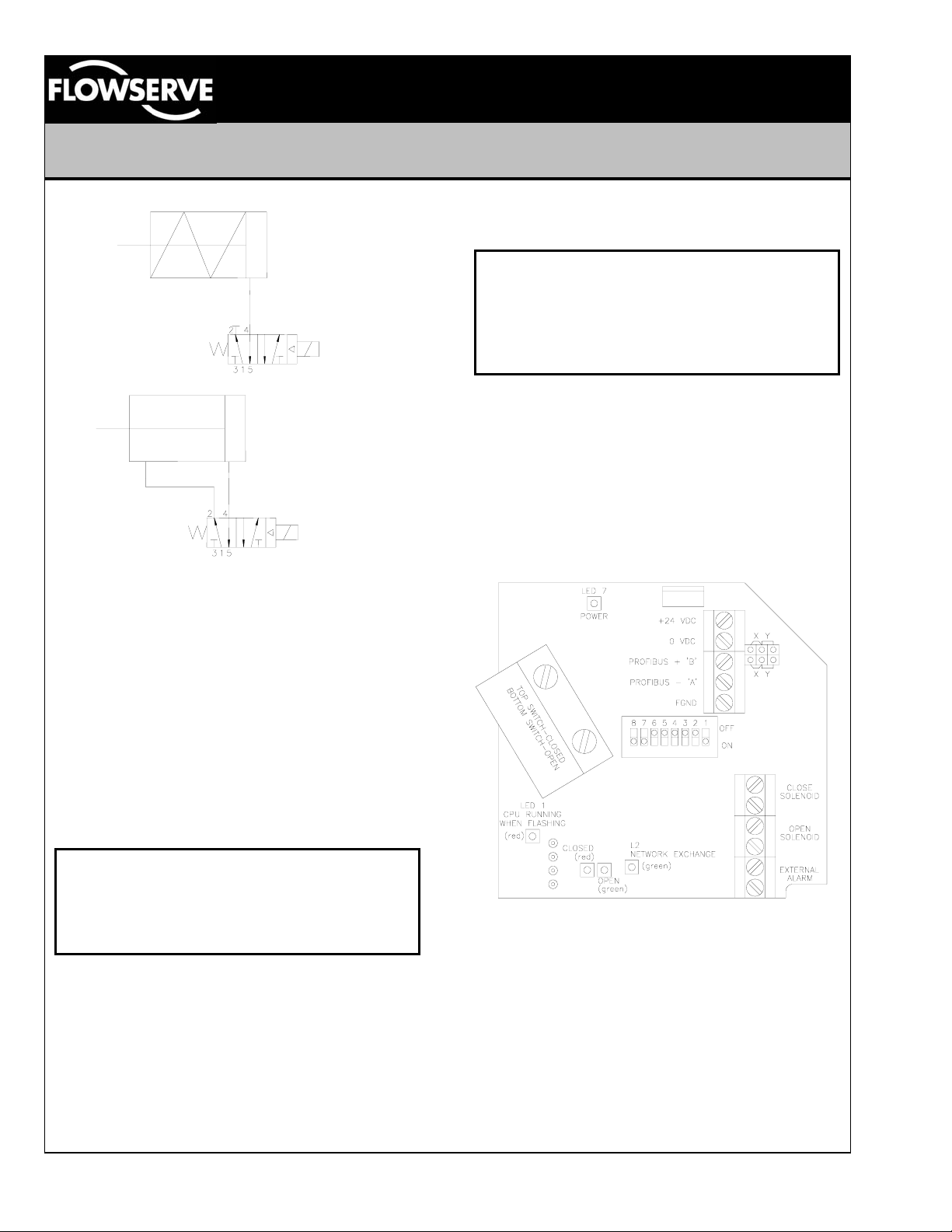
Spool and Tubing Configuration
1. For spring return actuators, a 4-way spool valve
is provided with port #2 plugged. For double
acting actuators, the same valve is provided with
no plugs. Make sure the correct spool is
selected before installing tubing. (Note: the
Flowserve APS2 purge module can be supplied
on spring return actuators to purge the spring
chamber with supply air.)
2. Make sure all air pressure is removed before
installing tubing.
3. Attach tubing according to Figures 1 or 2 below,
depending upon application. Attach supply
tubing to Port 1 and use 3 and 5 for exhaust.
4. To prolong actuator life use only clean, dry plant
air. Lubricated air is not required, although it is
recommended, particularly for high cycle
applications.
1.13
LML0012-0 8/99 Page 1 of 6
©1999, Flowserve Corporation, Provo, Utah
Page 2
Flowserve Corporation
Flow Control Division
Automax BUSwitchTM – Profibus-DP
765 South 100 East
Provo, Utah 84606
www.flowserve.com
Email: actuators@flowserve.com
Phone: 801 373 3028
Facsimile: 801 489 2228
Figure 1
Figure 2
Lubrication
All BUSwitch™ spool valves are pre-lubricated and
will operate dry (with no additional lubrication). The
use of lubricated air will not interfere with the
BUSwitch’s functioning. If air lubrication is used, the
oils listed below are popular, easily obtainable, fluids
that are recommended for use with the BUSwitch
spool valve: Gulf Harmony 47, Mobil DTE Medium,
Shell Tellus 29, Texaco Rondo B, Sohivis 47 and
Sunnis 921. Many other lubricants are acceptable
providing they do not contain detergents that will
attack Buna-N or Viton Seals.
Electrical Connections
marked ‘OPEN’ and ‘CLOSE’. External power (24
VDC) is connected to the indicated location.
CAUTION
BE SURE TO OBSERVE CORRECT POLARITY
OF THE EXTERNAL POWER CONNECTIONS
OR DAMAGE TO THE PRINTED CIRCUIT
BOARD WILL OCCUR!
A ‘dry-contact’ device can be connected to the
terminals marked ‘EXTERNAL ALARM’, the
meaning of which is determined by the customer.
Refer to figure three. The data cable connection is
made to the locations marked PROFIBUS + B and
PROFIBUS – A, observing polarity. If this is the last
device on the segment, move the shorting jumpers
to the Y position to enable the termination resistor.
Refer to figure three for data cable connection
locations.
CAUTION
To prevent ignition of hazardous atmospheres,
keep cover bolts tight while circuits are live.
Disconnect supply circuit before opening.
Entry into the BUSwitch housing is made through
three ½” NPT conduit entries. All electrical
connections (power, data, external alarm, open and
close solenoids) are made to captive screw cage
terminal strips located on the Profibus-DP Interface
board (XA0231). BUSwitch models with an internal
pilot valve will have the valve connected to the
appropriate circuit board terminals by the factory.
For dual solenoid applications, connect the
respective solenoids to the terminal strip locations
For hazardous locations, Underwriters Laboratories
(UL) and the National Electric Code (NEC) require
an approved sealing fitting within eighteen inches of
the switch enclosure. Sealing fittings are not
required for Division 2 non-incendive applications.
Open conduit entries must be closed after
installation using a close-up plug approved for
hazardous locations. Conduit and plugs must
engage a full five threads. Flowserve can provide
the sealing fitting with a union and junction box for
‘daisy chain’ wiring applications.
LML0012-0 8/99 Page 2 of 6
©1999, Flowserve Corporation, Provo, Utah
Profibus-DP Interface Card (XA0231)
Figure 3
Page 3

Flowserve Corporation
Flow Control Division
Automax BUSwitchTM – Profibus-DP
765 South 100 East
Provo, Utah 84606
www.flowserve.com
Email: actuators@flowserve.com
Phone: 801 373 3028
Facsimile: 801 489 2228
Special notes on the fieldbus cabling.
Due to the high-speed communication capability of
Profibus-DP networks, it is important to follow
established specifications closely to ensure full
communication capability. Governance of the
physical level requirements is specified in the
European Norm EN50170: "General Purpose Field
Communication System.” To obtain the maximum
communication capability it is highly recommended
to only use type ‘A’ cable as defined in table one
below. As a rule, data speed and maximum
segment length are inversely related. At 9.6 kBaud,
segment lengths up to 1200 meters are allowed. At
12 MBaud the segment length falls to 100 meters.
The following tables were obtained from The Rapid
Way to Profibus-DP by Manfred Popp; available
from the PROFIBUS Nutzerorganisation (PNO) as
order number 4.072. To order, contact the Profibus
Trade Organization (PTO) in your area.
Line Parameters
Line Type A Line Type B
Impedance (Ω)
Capacitance per
unit length (pF/m)
Loop resistance
(Ω/km)
Core diameter
(mm)
Core cross
section (mm
2
)
135 to 165 100 to 130
<30 <60
110 ---
0.64 >0.53
>0.34 >0.22
Table 1
Recommended Line Lengths
Transmission rate (kBaud) 9.6 19.2 93.75
Line Type A 1200 1200 1200
Line Type B 1200 1200 1200
Transmission rate (kBaud) 187.5 500 1500
Line Type A 1000 400 200
Line Type B 600 200 -
Transmission rate (kBaud) 1200
Line Type A 100
Line Type B -
Table 2
Adjustment of Switch Cams
1. Loosen five captive cover screws and remove
lid, turning slightly while lifting.
2. Place the actuator in the clock-wise (CW)
position and apply 24 VDC to the Profibus-DP
Interface Card.
3. Push down on the top cam (figure 4)
until it clears the splined coupler and
rotate clockwise until the CW LED (red)
is illuminated.
4. Release the cam and insure that it
fully engages the spline.
5. Place the actuator in the counterclockwise (CCW) position.
6. Pull up on the lower cam (figure 4)
until it clears its splined coupler and
rotate counter-clockwise until the
CCW LED (green) is illuminated.
7. Release the cam and insure that
it fully engages the spline.
Figure 4
8. Cycle the actuator to insure that
each LED is illuminated at the appropriate time.
Some minor readjustment might be necessary.
9. Clean base, lid flanges, and replace lid on base.
Make sure wires are NOT caught between
flanges, and tighten captive screws.
BUSwitch Configuration
Configuration of the BUSwitch is accomplished
through three main steps; physically connecting to
the network, setting the device address / operating
mode and sending operating parameters over the
Profibus segment. The physical connection to the
segment was covered previously in this document.
Setting of the device address and operating mode is
accomplished by a printed circuit board (PCB)
mounted switch assembly (refer to figure three).
The switch assembly has eight numbered positions,
each of which can be set to either ON or OFF.
Switch #1 sets dual coil operation when in the ON
position, or single coil operation when placed in the
OFF position. Switches 2 through 8 are used to set
the address of the BUSwitch on the Profibus
segment. The switches are a binary representation
of the address with switch number 2 being the most
significant digit and switch number 8 being the least
significant digit. The decimal value of each switch
when set to the ON position is as follows.
Switch # 2 3 4 5 6 7 8
Decimal Value 64 32 16 8 4 2 1
Table 3
LML0012-0 8/99 Page 3 of 6
©1999, Flowserve Corporation, Provo, Utah
Page 4

Flowserve Corporation
Flow Control Division
Automax BUSwitchTM – Profibus-DP
765 South 100 East
Provo, Utah 84606
www.flowserve.com
Email: actuators@flowserve.com
Phone: 801 373 3028
Facsimile: 801 489 2228
A simple algorithm that can be used to set the board
to a specific address is.
1. Put switches 2 through 8 into the OFF position.
2. Determine the address where the BUSwitch will
reside. This value will be known as the ‘target’
value.
3. Referring to Table 3, locate the switch with the
highest decimal value that is less than or equal
to the target value. Move that switch to the ON
position. For example if the target value is 33,
switch #3, with a decimal value of 32, would be
moved to the ON position.
4. Subtract the decimal value of the switch that
was just turned on from the target value. The
difference, if it is not equal to zero, will become
the new ‘target’ value. From the example
above, 1 will be the new target value (33-32=1).
5. Repeat steps 3 and 4 until the difference
between the switch value and the target value is
zero. Upon application of power to the board,
the address will be read from the switches.
Communication of the operating parameters to the
BUSwitch is accomplished by reading and writing of
six, 16-bit words. To ensure that the BUSwitch
sends and receives the correct data, all six words
should be read or written anytime one of the
parameters is changed.
Board Indicators
The Profibus-DP Interface Board (XA0231) contains
several indicators that are helpful when initially
configuring the device or when troubleshooting.
Refer to figure three for the locations of the
indicators.
BUSwitch Input Data Packet
Word
Bit→
1 2 3 4 5 6 7 8 9 10 11 12 13 14 15 16
LED 7 – Power Illuminated when 24 VDC is
present.
LED 1 – CPU Running When Flashing This
indicator will flash red approximately every 2
seconds to indicate that the microprocessor is
operating normally. If the indicator glows steadily or
does not come on, remove device power for 10
seconds and then reapply to reset.
L2 – Network Exchange This indicator will be
green when communication with the device is taking
place over the network.
Terminations
For proper communication to take place, each end
of the network segment must have terminators.
Terminators are resistive devices used to insure the
proper network impedance is maintained. In most
systems, one of the terminators will be located at the
PLC. The other terminator is located at the last
device on the segment. If the BUSwitch is the last
device on the segment, move the two jumpers on
the ‘X” locations over to the ‘Y’ locations to enable
the on board terminator. If the BUSwitch is located
within the center of the segment, the jumpers should
be set on the ‘X’ locations. Refer to figure five.
Figure 5
1
2
3
4
5
6
OP CL RS AL FA FO Reserved
Odometer Limit (Most significant word)
Odometer Limit (Least significant word)
Oneshot Duration ( 50 millisecond ‘ticks’ )
Valve Opening Response Timeout ( 50 millisecond ‘ticks’ )
Valve Closing Response Timeout ( 50 millisecond ‘ticks’ )
Table 4 – Input Data Packet
LML0012-0 8/99 Page 4 of 6
©1999, Flowserve Corporation, Provo, Utah
Page 5

Flowserve Corporation
Flow Control Division
Automax BUSwitchTM – Profibus-DP
765 South 100 East
Provo, Utah 84606
www.flowserve.com
Email: actuators@flowserve.com
Phone: 801 373 3028
Facsimile: 801 489 2228
OP (OPen) Changing this bit from a zero to a one
will result in the valve actuating to the open position
- only if the valve is in the closed position. If the
valve is currently in the ‘OPEN’ state, this bit will be
ignored. This bit is dependent on the value written
to the closed bit (CL). If CL contains a one when OP
is set to one, actuation will not occur until CL is
reset.
CL (CL
osed) Changing this bit from a zero to a one
will result in the valve actuating to the closed
position - only if the valve is in the open position. If
the valve is currently in the ‘CLOSED’ state, this bit
will be ignored. This bit is dependent on the value
written to the open bit (OP). If OP contains a one
when CL is set to one, actuation will not occur until
OP is reset.
RS (Odometer R
eSet) Setting this bit to a value of
one will result in the odometer counter being set to
zero subject to the following conditions:
1. RS is set to one
2. OP is set to zero
3. CL is set to zero
4. The odometer limit has all bits set to 1
5. No valve actuation is currently in process
AL (ALarm) The value written to this bit will affect
the meaning of the external alarm input of the
BUSwitch. When a zero is placed in this position,
the external alarm bit (EX) of the BUSwitch output
data packet will be set to a one when the connection
to the external alarm input terminals is broken.
Placing a one in this position will result in the EX bit
being set when a closed connection is made to the
external alarm input terminals.
FA (F
ailsafe Arm) If communication over the
network is lost, the default action of the valve is to
fail in place. By setting this bit to one, either fail
open or fail close can be enabled. The fail direction
is determined by the state of the FO bit described
below.
FO (F
ail Open) This bit determines the direction of
the fail action when the FA bit has been enabled.
When this bit is set to zero and the FA bit is set to
one, the valve will fail close upon loss of
communication with the master. If it is desired for
the valve to fail open, set this bit to one.
The following truth table illustrates the interactions
between the FA and FO bits.
FA FO Failsafe Action
0 0 Fail in place
0 1 Fail in place
1 0 Fail closed
1 1 Fail Open
Table 5
Odometer Limit: The odometer limit is a 32-bit
value that is comprised of words 3 and 4 of the input
data packet. When the odometer counter exceeds
this value, the Odometer Limit (LI) bit of the output
data packet is set to one, indicating an alarm
condition. When set to zero the BUSwitch will
default to 2,000,000. Valid range is from 0 to
4,294,967,295 (2
32
-1).
One-shot Duration: Integer value that when
multiplied by 0.05, represents the number of
seconds to energize the solenoids in dual coil mode.
Any integer value between 0 and 65535 can be
input, however, values below 10 (0.5 seconds) will
result in a value of 10 being used. Integer values
above 6000 (300 seconds) will result in 6000 being
used. To calculate the value to enter from a desired
time value, divide the time value by 0.05 and round
to the nearest integer.
Valve Opening Timeout / Valve Closing Timeout:
When a either the OPEN or CLOSE solenoid is
activated, the response time for the valve to
complete the transition is monitored and compared
to the limit specified by the user for that respective
operation. If the transition time exceeds the value
specified for that operation, the time-out (TO) bit will
be set to one in the BUSwitch output data packet.
As with the one-shot duration value above, the value
entered into these words represent 50 millisecond
intervals. Values entered that are below 10 (0.5
seconds) will default to 10 (0.5 second). Values
above 6000 (300 seconds) will default to 6000.
Allowable input range is from 0 to 65535.
LML0012-0 8/99 Page 5 of 6
©1999, Flowserve Corporation, Provo, Utah
Page 6

Flowserve Corporation
Flow Control Division
BUSwitch Output Data Packet
Word
Bit→
1 2 3 4 5 6 7 8 9 10 11 12 13 14 15 16
Automax BUSwitchTM – Profibus-DP
765 South 100 East
Provo, Utah 84606
www.flowserve.com
Email: actuators@flowserve.com
Phone: 801 373 3028
Facsimile: 801 489 2228
1
2
3
4
5
6
VO VC EX LI TO
Odometer Counter (Most significant word)
Odometer Counter (Least significant word)
Reserved
Transition Timer ( 50 millisecond ‘ticks’ )
Firmware Version
Table 6 – Output Data Packet
VO (Valve is Open) This reflects the actual state of
the valve position by monitoring the state of the
OPEN proximity switch. A one in this bit position
indicates the OPEN proximity switch is closed.
VC (V
alve is Closed) Reflects the actual state of the
valve by monitoring the CLOSED proximity switch.
A one in this position indicates the CLOSED
proximity switch is closed.
EX (EX
ternal Limit) This bit is set to one to indicate
an alarm condition depending on the state of the
external alarm input AND the value of the AL bit in
the input data packet. When AL is set to 0, if the
circuit connected to the external alarm input is
broken, the EX bit will be set to one. When AL is set
to 1, the circuit connected to the external alarm input
must be made for EX to be set.
LI (Odometer LI
mit) When the number of valve
transitions exceeds the odometer limit value, this bit
will be set to one.
TO (Valve T
imeOut) This bit is set when the valve
has not reached its end of travel within the time
specified by either Valve Opening Response
bit is cleared upon reversal of motion. For example,
if the TO bit was set during a close operation, it will
only clear when the valve has been commanded to
open and the valve subsequently leaves the closed
position.
Transition Timer: This integer value indicates the
number of 50 millisecond periods that have elapsed
since the last request of valve motion and
completion of the valve movement. This value is
reset to zero upon change of direction.
Odometer Counter: This value is the cumulative
number of valve transitions since the counter was
reset. The value is incremented when the valve
completes a transition.
Firmware Version: Expresses the firmware version
of the BUSwitch in decimal form. The value should
be divided by 100 to obtain the correct form. For
example, a value of 113 in this word corresponds to
firmware version 1.13.
Reserved bits are reported back to the controller as
zero.
Timeout or Valve Closing Response Timeout. This
0518 II 2 G EEx d II T5
LML0012-0 8/99 Page 6 of 6
©1999, Flowserve Corporation, Provo, Utah
 Loading...