

Page 1

AXAIM020-01 (AUTO-48) 3/03 Page 1 of 16
© 2003, Flowserve Corporation, Printed in U.S.A.
BUSwitch™with FOUNDATION®Fieldbus Protocol
Installation, Operating and Maintenance Instructions
Flowserve Corporation 1350 N. Mountain Springs Parkway 1978 Foreman Dr.
Flow Control Division Springville, Utah 84663-3004 Cookeville, TN 38501
www.flowserve.com Phone: 801 489 8611 Phone: 931 432 4021
BUSwitch
™
with
F
OUNDATION
®
Fieldbus Communications Protocol
Installation, Operating and Maintenance
Instructions
Page 2

AXAIM020-01 (AUTO-48) 3/03 Page 2 of 16
© 2003, Flowserve Corporation, Printed in U.S.A.
BUSwitch™with FOUNDATION®Fieldbus Protocol
Installation, Operating and Maintenance Instructions
Flowserve Corporation 1350 N. Mountain Springs Parkway 1978 Foreman Dr.
Flow Control Division Springville, Utah 84663-3004 Cookeville, TN 38501
www.flowserve.com Phone: 801 489 8611 Phone: 931 432 4021
Table of Contents
Introduction. . . . . . . . . . . . . . . . . . . . . . . . . . . . . . . 2
Principles of Operation . . . . . . . . . . . . . . . . . . . . . . 2
Printed Circuit Board Specifications . . . . . . . . . . . . . 3
Start-up Guide . . . . . . . . . . . . . . . . . . . . . . . . . . . . 3
Mechanical Installation . . . . . . . . . . . . . . . . . . . . . . 4
Lubrication . . . . . . . . . . . . . . . . . . . . . . . . . . . . . . . 4
Electrical Connections . . . . . . . . . . . . . . . . . . . . . . . 5
Adjustment of Switch Cams. . . . . . . . . . . . . . . . . . . 6
BUSwitch™Embedded Software Specs . . . . . . . . . . 6
Resource Block. . . . . . . . . . . . . . . . . . . . . . . . . . . . 7
Resource Block Parameter Table. . . . . . . . . . . . . . . 7
Transducer Block. . . . . . . . . . . . . . . . . . . . . . . . . . . 9
Pneumatic Actuator Operation. . . . . . . . . . . . . . . . . 9
Valve Position Monitoring and Reporting . . . . . . . . . 9
Auxiliary Dry Contact Input . . . . . . . . . . . . . . . . . . 10
Odometer . . . . . . . . . . . . . . . . . . . . . . . . . . . . . . . 10
Transducer Block Parameter Table. . . . . . . . . . . . . 11
DI Function Block Parameter Table . . . . . . . . . . . . 14
DO Function Block Parameter Table . . . . . . . . . . . 15
Introduction
Flowserve’s BUSwitch™uses the FOUNDATION
®
Fieldbus communication protocol to operate
pneumatic valve actuators and monitor/report their
position. BUSwitch™also provides an odometer and
stroke timer to assist in preventative maintenance.
Principles of Operation
BUSwitch™utilizes two discrete output function
blocks (DO-1 and DO-2) to energize piezo or
coil actuators, which act as pilots to shift a large
capacity spool valve.For spring retur n and double
acting applications with a desired fail position (open
or closed) DO-1 is used to operate a single pilot.
For applications requiring fail in last position,
both DO blocks are used with a “dual coil” pilot
configuration.
In dual coil mode, users may choose to de-energize
piezo/coil elements after the valve has reached its
desired position or may configure the elements to
remain energized (factory default)(see “Transducer
Block”).
Valve position is sensed with two limit switches.
BUSwitch™communicates the state of these limits
in the transducer block’s SOLENOIDE_CLOSED
and SOLENOIDE_OPENED parameters and in the
READBACK_D parameters of DO-1 and DO-2.
The transducer block’s ODOMETER parameter tracks
the number of valve strokes. It may be reset using
RESET_ODOMETER.
The transducer block’s transition alarm alerts the
used if the stroke time exceeds the time in the
parameter TIME_OUT, this alarm is also passed
to the OUT_D of the DI-1 block.
Two discrete input blocks are factory-configured.
DI-1 is a discrete value indicating the stroke exceeded
a specific time. DI-2’s OUT_D parameter provides a
link to an external dry-contact input (terminal P4).
This input is jumper-selectable to normally open or
normally closed (jumper J1/J2). Common uses for
this input include valve packing pressure monitoring.
A 2-wire cable using the FF H1 (31.25 Kbps)
protocol provides communication and power to the
FF Communication Board.The communications
board, switches, and piezo/coil pilots are all
connected to an interface board.Two versions
of this interface card are available:
• 2-Wire for bus-powered pilot applications.
Utilizes ultra-low power piezo pilot valves.
• 4-Wire for externally powered pilot applications.
Utilizes a wide range of 24VDC coil pilot valves.
The communications card operates from 9.5 to
32 VDC. BUSwitches are configured to draw
18 mA of current. Current consumption from the
fieldbus segment will remain constant whether a
piezo/coil actuator is activated or not.
Page 3

AXAIM020-01 (AUTO-48) 3/03 Page 3 of 16
© 2003, Flowserve Corporation, Printed in U.S.A.
BUSwitch™with FOUNDATION®Fieldbus Protocol
Installation, Operating and Maintenance Instructions
Flowserve Corporation 1350 N. Mountain Springs Parkway 1978 Foreman Dr.
Flow Control Division Springville, Utah 84663-3004 Cookeville, TN 38501
www.flowserve.com Phone: 801 489 8611 Phone: 931 432 4021
Start-up Guide
CAUTION
The BUSwitch™may cycle during a configuration download. Exercise caution in handling
valves that may be stroked during these
procedures.
For best results, Flowserve strongly recommends reading this entire document before
attempting to configure and commission
BUSwitches.
1 Following the instructions in “Mechanical
Installation,” install the BUSwitch™onto a
pneumatic actuator and turn supply air on.
2. Following the instructions in “Electrical connections,” connect fieldbus and optional dry-contact
wiring.
3. Referring to control system or configuration system
documentation, install BUSwitch™device description (DD) files onto system hard drive. Note:
Readme file on DD floppy contains instructions.
Note: For Fisher DeltaV systems, the DD files
must be copied to a directory or folder named
“464C4F” in order for the system to find them.
4. Initialize communications with device and bring
up the “Live List.” BUSwitches have been
configured from the factory with an ID of
“464C4F5053:BUSWITCH: [serialnumber]” and
a default tag of “FLOWSERVE BUSWITCH.”
Note the serial number.
5. Change the BUSwitch™attribute Device ID to the
value noted in step 4 and change the Device Tag
to the appropriate value.
6. Assign the Tag configuration in step 5.
7. BUSwitches are shipped with resource block,
transducer block, (2) DO blocks and (2) DI blocks
pre-configured unless specially configured by
agreement with customer.Refer to the appropriate
sections in this manual for the default configuration.
Make any desired changes to this configuration
and download.
Printed Circuit Board Specifications
F
OUNDATION
®
Fieldbus Information
Power Requirements: Communications Card
XA0239
Communication Card
Power requirements: 2-Wire Version
XA0238 Interface
Card Version 2.0
Power requirements
XA0242 Interface
Card
Temperature
Operational -40°F to +185°F
Storage -40°F to + 250°F
†
To operate, an external 24 VDC source must be locally
supplied to the interface card.
Bus powered
9.5-32 VDC at 18 mA
Bus powered by
XA0239 Communication
Card
†
: 4-Wire Version
24 VDC
• 10 mA quiescent
• 510 mA max. with
solenoid activat
(-40°C to + 85 °C)
(-40°C to + 120°C)
ed
Manufacturer
ID 464C4F (Hex)
Name 46 6C 6F 77 73 65 72 76 65
Device
Type 0x0x5053 (Hex)
ID
Device Descriptions are supplied on included
disk
ette
F l o w s e r v e
464C4F5053:BUSWITCH:xxxxxx
Max. length of 32 characters.
Characters 21 through 32 are
used for board serial number
.
Page 4
BUSwitch™with FOUNDATION®Fieldbus Protocol
Installation, Operating and Maintenance Instructions
Flowserve Corporation 1350 N. Mountain Springs Parkway 1978 Foreman Dr.
Flow Control Division Springville, Utah 84663-3004 Cookeville, TN 38501
www.flowserve.com Phone: 801 489 8611 Phone: 931 432 4021
8. Using the DO-1.OUT_D value parameter (and
DO-2.OUT_D for dual coil mode), stroke the valve
(Discrete 0 = de-energized; Discrete 1 = energized)
and set limit switches, referring to “Adjustment of
Switch Cams” section. Circuit board mounted LED’s
light when switches are tripped.
9. This is the minimum configuration to operate
the actuator and read valve position.Refer to
FOUNDATION®Fieldbus standards for DO and DI
blocks to establish more sophisticated control
strategies. Refer to the block sections in this manual
for more information on BUSwitch™functionality.
Mechanical Installation
BUSwitch™Mounting:
1. Installation is best performed with Flowserve
NAMUR mounting kits.These kits allow direct
mounting of the BUSwitch™shaft to the actuator
pinion without a coupler.The NAMUR mounting
kits will work with any actuator conforming to the
NAMUR standard for accessory mounting hole
locations and pinion dimensions. Simply attach the
bracket to actuator and BUSwitch™to the bracket
with the included fasteners.The BUSwitch™shaft
features an integral alignment pin that engages the
tapped pinion hole. Flowserve also offers a full line
of non-NAMUR mounting kits.
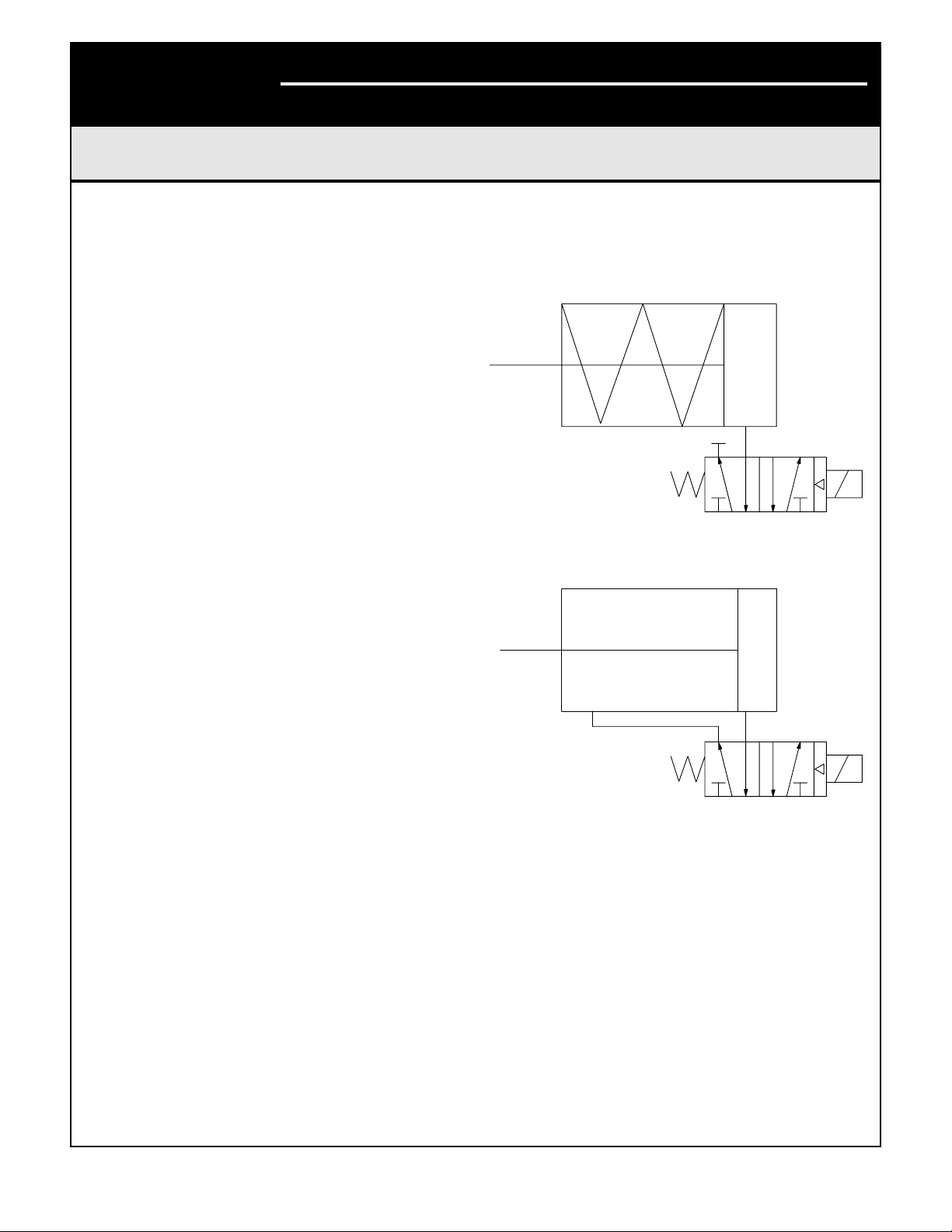
Spool and Tubing Configuration:
The following instructions apply to BUSwitch™configured with integral pilot valves and spool valve.For
non-integral pilot/spool valves, follow manufacturer's
instructions for piping.
1. For spring return actuators, a 4-way spool valve is
provided with port #2 plugged. For double acting
actuators, the same valve is provided with no
plugs. Make sure the correct spool is selected
before installing tubing.
2. Make sure all air pressure is removed before
installing tubing.
3. Attach tubing according to Figures 1 or 2 at right,
depending upon application. Attach supply tubing
to Port 1 and use 3 and 5 for exhaust.
4. To prolong actuator life use only clean, dry plant
air.Lubricated air is not required, although it is recommended, particularly for high cycle applications.
4
2
315
531
2 4
Figure 1
Figure 2
Lubrication
All BUSwitch™spool valves are pre-lubricated
and will operate dry (with no additional lubrication).
The use of lubricated air will not interfere with the
functioning of the BUSwitch™. If air lubrication
is used, the oils listed below are popular, easily
obtainable, fluids that are recommended for use
with the BUSwitch™spool valve:Gulf Harmony 47,
Mobil DTE Medium, Shell Tellus 29, Texaco Rondo B,
Sohivis 47 and Sunnis 921. Many other lubricants are
acceptable providing they do not contain detergents
that will attack Buna N or Viton Seals.
AXAIM020-01 (AUTO-48) 3/03 Page 4 of 16
© 2003, Flowserve Corporation, Printed in U.S.A.
Page 5
Electrical Connections
CAUTION
To prevent ignition of hazardous atmospheres, keep cover bolts tight while circuits
are live. Disconnect supply circuit before
opening.
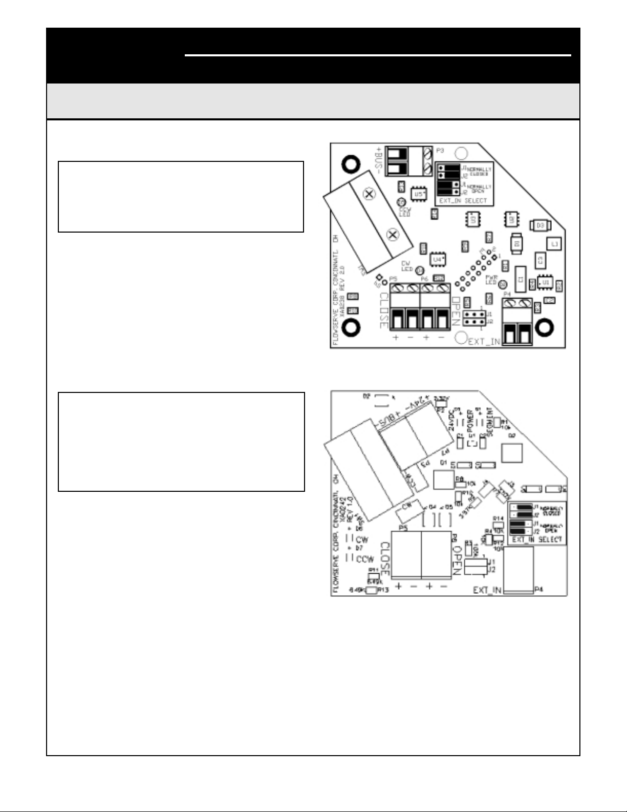
Entry into the BUSwitch™housing is made through
three 1/2
” NPT conduit entries. Figures 3 and 4
provide terminal locations on the interface card.
Connection of the data cable is made to connector
P3 – observing polarity.Incorrect polarity will not
damage the electronics, but it will prevent communication. For hazardous locations, Underwriters
Laboratories (UL) and the National Electric Code
(NEC) require an approved sealing fitting within
eighteen inches of the switch enclosure.Sealing
fittings are not required for Division 2 non-incendive
applications.
CAUTION
Make sure power is turned off when making
electrical connection. Inadvertent power
cycling will result in BUSwitch
™
shutdown.
After a power shut-down wait at least five
seconds before attempting to turn power
back on to assure BUSwitch™start-up.
Open conduit entries must be closed after installation
using a close-up plug approved for hazardous
locations. Conduit and plugs must fully engage
five threads.
Ter minal P4 is provided for the input of a signal from
an external dry-contact switch. Jumper J1 and J2
change the configuration of this input. Factory setting
is Normally Closed with DI-2 OUT_D value Discrete
1 = contact open and Discrete 0 = contact closed.
Change the jumper setting to “normally open” for
Discrete 0 = contact open.
AXAIM020-01 (AUTO-48) 3/03 Page 5 of 16
© 2003, Flowserve Corporation, Printed in U.S.A.
BUSwitch™with FOUNDATION®Fieldbus Protocol
Installation, Operating and Maintenance Instructions
Flowserve Corporation 1350 N. Mountain Springs Parkway 1978 Foreman Dr.
Flow Control Division Springville, Utah 84663-3004 Cookeville, TN 38501
www.flowserve.com Phone: 801 489 8611 Phone: 931 432 4021
Figure 3
Interface Card: 2-Wire Version XA0238
Figure 4
Interface Card: 4-Wire Version XA0242
Page 6

AXAIM020-01 (AUTO-48) 3/03 Page 6 of 16
© 2003, Flowserve Corporation, Printed in U.S.A.
BUSwitch™with FOUNDATION®Fieldbus Protocol
Installation, Operating and Maintenance Instructions
Flowserve Corporation 1350 N. Mountain Springs Parkway 1978 Foreman Dr.
Flow Control Division Springville, Utah 84663-3004 Cookeville, TN 38501
www.flowserve.com Phone: 801 489 8611 Phone: 931 432 4021
Special Notes on the fieldbus cabling
Minimum voltage requirement for the BUSwitch
™
is 9.5 VDC supply. The output voltage of the fieldbus
power supply, the current drawn and the electrical
characteristics of the data cable determine the maximum distance that a particular segment can span.
With data cable that conforms to the FF cable type ‘A’
specification, distances of 1900 meters are guaranteed. If a shielded cable is used, connect the shield to
ground at one point only. Multiple grounds can lead
to ground loops which can impair the proper operation of the segment. For this reason, a shield connection has not been provided inside the BUSwitch
™
housing. Radio frequency grounding at multiple
points through the use of capacitors, allowed by
the FF protocols, can be used for increased high
frequency EMI (electromagnetic interference)
shielding. For a more thorough treatment of data
cable wiring and aspects of installation refer to the
FOUNDATION®Fieldbus application guide AG-140:
Wiring and Installation 31.25 Kbit/s,Voltage Mode,
Wire Medium. Its reference section lists additional
documentation that can be consulted for further
information.
Adjustment of Switch Cams
1. Loosen five captive cover screws
and remove lid, turning slightly
while lifting.
2. Place the actuator in the clock-wise
(CW) position and connect to the
fieldbus segment.
3. Push down on the top cam until it
clears the splined coupler, rotating
clockwise until the CW LED is
illuminated (Figure 5).
4. Release the cam and insure that
it fully engages the spline.
5. Place the actuator in the counterclockwise (CCW) position.
6. Pull up on the lower cam until it clears its
splined coupler, rotating counter-clockwise
until the CCW LED is illuminated (Figure 5).
BUSwitch™Embedded Software
Specifications
Flowserve’s BUSwitch™utilizes the SMAR communications stack. Factory-configured embedded software
includes the resource block, transducer block,
(2) DO blocks and (2) DI blocks.The next sections
provide information about each of these blocks.
Flowserve assumes the reader has a fundamental
understanding of the nature, nomenclature, and
geometry of these blocks.
DISCLOSURE
The Flowserve BUSwitch™has been certified by
FOUNDATION®Fieldbus (FF) to be interoperable
in accordance with FF standards. In addition, the
BUSwitch™device has been proven interoperable
with Fisher’s DeltaV Control System.The term
interoperable DOES NOT mean the BUSwitch
™
device will behave exactly like other FF-interoperable
devices.Because of some flexibility in the interpretation of FF standards, some minor differences exist
between many manufacturers.These differences
DO NOT affect the function of this device.
Flowserve has disclosed, in an addendum to this
document, known issues with individual control
systems we have tested.Users and systems
integrators should make allowances for these
issues. Flowserve will not be responsible for
modifying software to change the behavior of the
BUSwitch™relative to these issues.
Figure 5
Page 7

AXAIM020-01 (Auto-48) 3/03 Page 7 of 16
© 2003, Flowserve Corporation, Printed in U.S.A.
BUSwitch™with FOUNDATION®Fieldbus Protocol
Installation, Operating and Maintenance Instructions
Flowserve Corporation 1350 N. Mountain Springs Parkway 1978 Foreman Dr.
Flow Control Division Springville, Utah 84663-3004 Cookeville, TN 38501
www.flowserve.com Phone: 801 489 8611 Phone: 931 432 4021
Resource Block Parameter Table
Resource Block
The Resource Block (RB) contains a set of parameters that define characteristics of the physical
BUSwitch™sub-components (function blocks and
transducer block).Some of these parameters are
considered “operational” because they affect or reflect
the operation of function blocks.Others contain more
general data about the device.
MANUFAC_ID, DEV_TYPE, DEV_REV, and DD_REV
provide information to the control system about which
device description to use. All of the RB parameter
data is “contained” meaning no links are made to
this block.No device configuration data is stored in
this block.
General function block operation is reflected in the
RB. MODE_BLK may be used to override the Target
Modes of all function blocks and transducer block.
Supported Modes (MODE_BLK)
O/S, IMAN, AUTO (Factory default = Auto)
Alarm Types
Standard block alarm plus a discrete alarm for
write lock.
Device Initialization
The parameter RESTART permits varying degrees
of initialization.
CAUTION
Initializing with the setting “Defaults” will
reset the device to the board manufacturer’s
defaults, not the Flowserve defaults shown in
this document.When using this command,
users will have to reestablish all the critical
Flowserve factory defaults highlighted in each
block section. Items shaded “black” must be
configured.
1.Write the value “Defaults” to RESTART.
2. Read the RESTART value. It should equal 1.
3.Turn off and then tur n on the device.
Users may utilize the other levels of restart at their
discretion.
Resource Block Parameter Table
The following table provides a complete list of all
RB parameters.There are no cr itical default RB
parameter settings affected by a “Default” RESTART,
however Flowserve recommends setting the
MODE_BLK value to “Auto.”
Rel.
Index
1 ST_REV The revision level of the static data associated with the function block. To support
2 TAG_DESC The user description of the intended application of the block.
3 STRATEGY The strategy field can be used to identify grouping of blocks. This data is not
4 ALERT_KEY The identification number of the plant unit. This information may be used in the host
5 MODE_BLK The actual, target, permitted, and normal modes of the block.
6 BLOCK_ERR This parameter reflects the error status associated with the hardware or software
7 RS_STATE State of the function block application state machine.
8 TEST_RW Read/write test parameter – used only for conformance testin
9 DD_RESOURCE String identifying the tag of the resource, which contains the Device Description for
10 MANUFAC_ID Manufacturer identification number – used by an interface device to locate the DD file
Parameter Description
tracking changes in static parameter attributes, the associated blockís static revision
parameter will be incremented each time a static parameter attribute value is writt
checked or processed by the block.
for sorting alarms, etc.
components associated with a block. It is a bit string, so that multiple errors may be
shown.
this resource
for the resource
en.
g.
.
.
Page 8

AXAIM020-01 (AUTO-48) 3/03 Page 8 of 16
© 2003, Flowserve Corporation, Printed in U.S.A.
BUSwitch™with FOUNDATION®Fieldbus Protocol
Installation, Operating and Maintenance Instructions
Flowserve Corporation 1350 N. Mountain Springs Parkway 1978 Foreman Dr.
Flow Control Division Springville, Utah 84663-3004 Cookeville, TN 38501
www.flowserve.com Phone: 801 489 8611 Phone: 931 432 4021
Rel.
Index
11 DEV TYPE Manufacturer’s model number associated with the resource – used by interface
12 DEV__REV Manufacturer revision number associated with the resource – used by an interface
13 DD_REV Revision of the DD associated with the resource – used by an interface device to
14 GRANT_DENY Options for controlling access of host computer and local control panels to operating,
15 HARD_TYPES The types of hardware available as channel numbers.
16 RESTART Allows a manual restart to be initiated. Several degrees of restart are possible. They
17 FEATURES Used to show supported resource block options
18 FEATURE_SEL Used to select resource block options
19 CYCLE_TYPE Identifies the block execution methods available for this resource
20 CYCLE_SEL Used to select the block execution method for this resource
21 MIN_CYCLE_T Time duration of the shortest cycle interval of which the resource is capab
22 MEMORY_SIZE Available configuration memory in the empty resource. To be checked before
23 NV_CYCLE_T Minimum time interval specified by the manufacturer for writing copies of NV
24 FREE_SPACE Percent of memory available for further configuration. Zero in a pre-configured
25 FREE_TIME Percent of the block processing time that is free to process additional blocks
26 SHED_RCAS Time duration at which to give up on computer writes to function block RCAS
27 SHED_ROUT Time duration at which to give up on computer writes to function block ROUT
28 FAULT_STATE Condition set by loss of communication to an output block. When FAULT_STATE
29 SET_FSTATE Allows the FAULT_STATE condition to be manually initiat
30 CLR_FSTATE Writing to this parameter will clear the FAULT_STATE condition as long as the
31 MAX_NOTIFY Maximum number of unconfirmed notify messages possible.
32 LIM_NOTIFY Maximum number of unconfirmed alert notify messages allowed.
33 CONFIRM_TIME The time the resource will wait for confirmation of receipt of a report before trying
34 WRITE_LOCK If set, writes to parameters within the device are not allowed, except to clear
35 UPDATE_EVT This alert is generated by any change to the static data
36 BLOCK_ALM The block alarm is used for all configuration, hardware, connection failure, or system
37 ALARM_SUM The current alert status, unacknowledged states, unreported states, and disabled
38 ACK_OPTION Selection of whether alarms associated with the block will be automatically
39 WRITE_PRI Priority of the alarm generated by clearing the write lock.
40 WRITE_ALM This alert is generated if the write lock parameter is clear
Parameter Description
devices to locate the DD file for the resource.
device to locate the DD file for the resource
locate the DD file for the resource
tuning and alarm parameters of the block.
are 1: Run, 2: Restart resource, 3: Restart with defaults, and 4: Restart processor.
attempting a download. MIN_CYCLE_T Time duration of the shortest cycle interval
of which the resource is capab
parameters to non-volatile memory. Zero means it will never be automatically copi
resource
locations. Shed from RCAS shall never happen when SHED_RCAS =
locations. Shed from Rout shall never happen when SHED_ROUT
condition is set the function blocks will perform their FSTATE actions.
problem which initially caused the FAULT_STATE has been clear
again. Retry shall not happen when CONFIRM_TIME
WRITE_LOCK. Block inputs will continue to be updated
problems in the block. The cause of the alert is entered in the subcode fiel
states of the alarms associated with the function block.
acknowledge
.
.
.
.
.
.
.
le.
le.
ed.
.
0.
= 0.
ed.
ed.
= 0.
.
.
d.
d.
ed.
Page 9

AXAIM020-01 (AUTO-48) 3/03 Page 9 of 16
© 2003, Flowserve Corporation, Printed in U.S.A.
BUSwitch™with FOUNDATION®Fieldbus Protocol
Installation, Operating and Maintenance Instructions
Flowserve Corporation 1350 N. Mountain Springs Parkway 1978 Foreman Dr.
Flow Control Division Springville, Utah 84663-3004 Cookeville, TN 38501
www.flowserve.com Phone: 801 489 8611 Phone: 931 432 4021
Transducer Block
The Transducer Block (TB) provides the link between
standard function blocks (DO-1, DO-2, DI-1, & DI-2)
and the sensors and piezo/coil actuators within the
BUSwitch™device.It tracks number of valve strokes.
The TB also provides some configuration flexibility.
This section details those parameters affecting the
function and configuration of the BUSwitch™device.
This discussion includes all operational aspects
of the function blocks as well. A complete list of
TB parameters follows at the end of the section.
Complete function block parameter lists are
provided in Appendices A and B.
Pneumatic Actuator Operation – Single Coil,
Fail Open or Fail Closed
For operation requiring a consistent fail position
(either open or closed), select the “Single Coil”
TB.OPERATION parameter. One DO block (DO-1)
is used.The TB reads DO-1 OUT_D Value and
energizes both the OPEN (P6) and CLOSE (P5)
terminals as shown in the Single Coil Truth Table.
To reverse the actuator fail mode for double acting
actuators, reverse ports 2 and 4. To reverse springreturn actuators, actuator modification is necessary.
Single Coil T ruth T able
When in Auto mode, DO1.OUT_D follows the SP_D
Value. If the user wishes to invert the above truth
table relative to SP_D, change the function block
IO_OPTS parameter to “Invert.” This will energize the
coil on an SP_D Discrete 0 and de-energize on an
SP_D Discrete 1.This toggle has the same effect
when “dual coil” mode is selected; it is necessar y to
select “Invert” for both DO blocks.
Pneumatic Actuator Operation – Dual Coil,
Fail in Last Position
Select the “Dual Coil”TB.OPERATION parameter.
Dual Coil Operation uses both DO1.OUT_D and
DO2.OUT_D block parameters configured in an
interlocking manner.For valve movement to take
place, the OUT_D parameters must take on opposite
values as shown in the next table.
Dual Coil T ruth T able
Referring to Figure 2, energizing the “OPEN” terminals will provide air to Port 4 and energizing the
“CLOSE” ter minals will provide air to Port 2. To
reverse the valve operation, either reverse the
solenoid valve wires on P5 and P6, or reverse the
actuator tubing connections on Port 2 and 4.
The TB.OUTPUT_CONFIGURATION parameter
selects whether solenoid pilot elements stay
energized or become de-energized after the valve
reaches its desired position. If the “Pulse” option
is selected, the elements will de-energize after
the length of time selected in the TB.TIME_OUT
parameter.The “Constant” setting maintains
element voltage until new DO-1 and DO-2 OUT_D
values are selected.
Valve Position Monitoring and Reporting
The BUSwitch
™
TB monitors the status of two limit
switches.SW1 is the upper switch and is set to trip
when the valve reaches the closed position.SW2 is
the lower switch and is set to trip when the valve is
open.The TB.SOLENOIDE_CLOSED parameter
displays SW1 status as False when not tripped and
Tr ue when tripped. TB.SOLENOIDE_OPENED
parameter displays SW2 status the same way.
The TB provides limit switch status to the READBACK_D parameters of DO-1 and DO-2 respectively
per the following truth table.
T ruth T able for READBACK_D V alues
FOUNDATION®Fieldbus DO blocks write the READBACK_D value to the PV_D variable within each
block.PV_D may then be linked to the BKCAL_OUT
variable.Figure 6 shows a schematic of a DO block
illustrating this feature.
DO1.OUT_D OPEN/CLOSE
0
1
De-energized
Energized
DO1
OUT_D
0 0
1 Energized De-ener
1 1
0 De-energized Ener
DO2
OUT_D
0
1
OPEN CLOSE
No Change No Change
gized
No Change No Chang
gized
e
SW1 SW2 DO-1
RDBK
A A 1 1 Improper switch adj.
A
O 0 1 Actuator O
O O 0 0 Actuator is moving
A = Activated or Tripped, O = Open or Not Tripped
O 1 0 Actuator CLOS
A
DO-2
RDBK
Meaning
ED
PENED
Page 10

AXAIM020-01 (AUTO-48) 3/03 Page 10 of 16
© 2003, Flowserve Corporation, Printed in U.S.A.
BUSwitch™with FOUNDATION®Fieldbus Protocol
Installation, Operating and Maintenance Instructions
Flowserve Corporation 1350 N. Mountain Springs Parkway 1978 Foreman Dr.
Flow Control Division Springville, Utah 84663-3004 Cookeville, TN 38501
www.flowserve.com Phone: 801 489 8611 Phone: 931 432 4021
To link DO.PV_D to DO.BKCAL_OUT, configure
the IO_OPTS for the desired block to “PV for
BKCAL_OUT.” Note: This action prevents the use
of “Invert” as an IO Option. Then, link BKCAL_OUT
to the BKCAL_IN of the function block sending the
CAS_IN_D signal.
Auxiliary Dry Contact Input
The BUSwitch™TB also monitors continuity across
terminals P4. This status is seen in the external alarm
parameter and in the OUT_D of DI-2. DI-2.OUT_D
will read Discrete 1 when no continuity exists and the
“Normally Closed” J1 and J2 jumpers are selected.
When contact is made in this jumper mode, the output changes to Discrete 0.
To reverse the outputs, change the J1 and J2 settings
to “Normally Open.” Refer to Figures 3 and 4 for the
jumper settings.
Odometer Function
TB Parameter ODOMETER reports the number of
open-closed and closed-open transitions. It may be
reset using the RESET_ODOMETER parameter.
Simply write a “True” value to this parameter to reset.
Valve Stroke Time Out Function
The BUSwitch™times each valve stroke and
reports the time from the move command until the
appropriate position switch is tripped.The stroke
time is displayed in the transducer block parameter
“TRANSITION TIME.” If the “TRANSITION TIME” is
greater than the value entered in “TIME-OUT,” an
alarm is generated.This alarm is displayed in the
transducer block parameter “TRANSITION-ALARM”
and is also sent to the DI-1 block “OUT-D.” This is
a “linkable” input and can be used to alter process
control.The alarm will stay present until the “RESETTIMEOUT” parameter is set to “TRUE” in the transducer block.
Additional TB Parameter s
Several TB parameters exist to store information
about the valve, actuator and BUSwitch™device.
In addition, calibration information may be stored.
Refer to the complete list of BUSwitch™TB
parameters starting on page 11 for a description
of these parameters.
Figure 6 – DO Block Schematic
Page 11

AXAIM020-01 (AUTO-48) 3/03 Page 11 of 16
© 2003, Flowserve Corporation, Printed in U.S.A.
BUSwitch™with FOUNDATION®Fieldbus Protocol
Installation, Operating and Maintenance Instructions
Flowserve Corporation 1350 N. Mountain Springs Parkway 1978 Foreman Dr.
Flow Control Division Springville, Utah 84663-3004 Cookeville, TN 38501
www.flowserve.com Phone: 801 489 8611 Phone: 931 432 4021
Transducer Block Parameters
Rel.
Index
1 ST_REV The revision level of the static data associated with the function
2 TAG_DESC The user description of the intended application of the block.
3 STRATEGY The strategy field can be used to identify grouping of blocks. This
4 ALERT_KEY The identification number of the plant unit. This information may
5 MODE_BLK Auto The actual, target, permitted, and normal modes of the block.
6 BLOCK_ERR This parameter reflects the error status associated with the
7 UPDATE_EVT This alert is generated by any change to the static data
8 BLOCK_ALM The block alarm is used for all configuration, hardware, and
9 T RANSDUCER_DIREC
10 TRANSDUCER_TYPE Identifies the transducer that follows.
11 XD_ERROR One of the error codes defined in section 4.8 of the FF-903
12 COLLECTION_DIREC
13 FINAL_VALUE_D The requested valve position and status written by a discrete
14 ACT_FAIL_ACTIN Specifies the final failure position of the actuator as defined in
15 ACT_MAN_ID 4607055 The BUSwitch manufacturer identification number
16 ACT_MODEL_NUM The actuator model number
17 ACT_SN The actuator serial number
18 VALVE_MAN_ID The valve manufacturer identification number
19 VALVE_MODEL_NUM The valve model number
20 VALVE_SN The valve serial number
21 VALVE_TYPE The type of the valve as defined in section 4.7 of the FF-903
22 XD_CAL_LOC The location of last calibrati
23 XD_CAL_DATE Date of the last calibration.
24 XD_CAL_WHO Name of the person responsible for last calibratio
Parameter Factory
Default
A directory that specifies the number and starting indices of the
TORY
A directory that specifies the number, starting indices, and DD
TORY
Description
block. To support tracking changes in static parameter attributes,
the associated block’s static revision parameter will be
incremented each time a static parameter attribute value is
changed. Also, the associated block’s static revision parameter
may be incremented if a static parameter attribute is written but
the value is not change
data is not checked or processed by the block.
be used in the host for sorting alarms, etc.
hardware or software components associated with a block. It is a
bit string, so that multiple errors may be show
connection failure or system problems in the block. The cause of
the alert is entered in the sub-code field. The first alert to become
active will set the Active status in the Status attribute. As soon as
the Unreported status is cleared by the alert reporting task,
another block alert may be reported without clearing the Active
status, if the sub-code has change
transducers in the transducer block.
document on the XD_ERROR and Block Alarm sub-codes.
Item IDs of the data collections in each transducer within a
transducer block.
Function Block.
section 4.6 of the FF-903 document on the Actuator Failure
Actions.
document on the Valve Type
d.
n.
.
d.
.
.
.
.
.
.
.
on.
n.
Page 12

AXAIM020-01 (AUTO-48) 3/03 Page 12 of 16
© 2003, Flowserve Corporation, Printed in U.S.A.
BUSwitch™with FOUNDATION®Fieldbus Protocol
Installation, Operating and Maintenance Instructions
Flowserve Corporation 1350 N. Mountain Springs Parkway 1978 Foreman Dr.
Flow Control Division Springville, Utah 84663-3004 Cookeville, TN 38501
www.flowserve.com Phone: 801 489 8611 Phone: 931 432 4021
Transducer Block Parameter Specifications
Rel.
Index
Parameter Mnemonic Data
Type
Size Valid
Range
Units Class
1 ST_REV Unsigned 16 2 Positive N/A Read
2 TAG_DESC Visible String 32 String Data N/A R/W
3 STRATEGY Unsigned 16 2 N/A R/W
4 ALERT_KEY Unsigned 8 1 1-255 N/A R/W
5 MODE_BLK DS-69 4 N/A R/W
6 BLOCK_ERR Bit String 2 N/A
Read
7 UPDATE_EVT DS-73 5 N/A
Read
8 BLOCK_ALARM DS-72 13 N/A
Read
9 TRANSDUCER_DIRECTORY Unsigned 16
Array
Variable N/A
Read
10 TRANSDUCER_TYPE Unsigned 16 2 E
R/W
11 XD_ERROR Unsigned 8 1 N/A
Read
12 COLLECTION_DIRECTORY Unsigned 32
Array
Variable
N/A
13 FINAL_VALUE_D DS-66 2 N/A R/W
14 ACT_FAIL_ACTION Unsigned 8 1 0=Undefined
1=Close
2=Open
3=Last
ER/W
R/W
R/W
15 ACT_MAN_ID Unsigned 32 4
E
Rel.
Index
25 OPERATION Note 1 Configures the piezo/coil element terminals for single coil or dual
26 OUTPUT_CONFIGUR
27 ODOMETER This variable counts the transitions from open to closed and
28 RESET_ODOMETER Resets the ODOMETER counter.
29 FAILURE_RECOVERY Enable/Disable FAILURE_RECOVERY action.1: Act with or
30 RESET_TIMEOUT Resets a TIME_OUT occurrenc
31 TRANSITION_TIME How much time for the last transiti
32 TIME_OUT 10 The time allowed for a transition before the DI associated with the
33 SOLENOIDE_CLOSED SW1 state
34 SOLENOIDE_OPEND SW2 st
35 TRANSITION_ALARM DI1 state = transition TIME-OUT st
36 EXTERNAL_ALARM DI2 state = It read the status of the Temperature/Pressure Limit
37 ACTION_TIME Time since last command for transition.
Notes:
1. Selected by Factory in accordance with customer PO specifications.
Parameter Factory
Default
Note 1 Configures the piezo/coil signals to shut-off or remain continuous
ATION
Description
coil modes
after TIME_OUT period. Applies to Dual Coil mode only
closed to open states. It is reset-able to 0, after maintenanc
without change in the input, 2: Do not act until a new change in the
inpu
TIME-OUT Alarm is Activated. Also, the length of the One-Shot
pulse voltage output to the coils in the Dual Coil Operation Mo
(CN1.12 pin) Data is passed on to DI2.
.
.
e.
t.
e.
on.
de.
ate
ate
Page 13

AXAIM020-01 (AUTO-48) 3/03 Page 13 of 16
© 2003, Flowserve Corporation, Printed in U.S.A.
BUSwitch™with FOUNDATION®Fieldbus Protocol
Installation, Operating and Maintenance Instructions
Flowserve Corporation 1350 N. Mountain Springs Parkway 1978 Foreman Dr.
Flow Control Division Springville, Utah 84663-3004 Cookeville, TN 38501
www.flowserve.com Phone: 801 489 8611 Phone: 931 432 4021
Rel.
Index
16 ACT_MODEL_NUM Visible String 32 String Data N/A
17 ACT_SN Visible String 32 String Data
18 VALVE_MAN_ID Unsigned 32 4
19 VALVE_MODEL_NUM Visible String 32 String Data
20 VALVE_SN Visible String 32 String Data
21 VALVE_TYPE Unsigned 8 1 N/A R/W
22 XD_CAL_LOC Visible String 32 N/A R/W
23 XD_CAL_DATE Time of Day 7 N/A R/W
24 XD_CAL_WHO Visible String 32 N/A R/W
25 OPERATION Unsigned 8 1 1=Single
26 OUTPUT_CONFIGURATION Unsigned 8 1 1=Pulse
27 ODOMETER Unsigned 32 4 N/A
28 RESET_ODOMETER Unsigned 8 1 True/False N/A R/W
29 FAILURE_RECOVER Unsigned 8 1 1=Enabled
30 RESET_TIMEOUTS Unsigned 8 1 True/False N/A R/W
31 TRANSITION_TIME Float 4 Sec.
32 TIME_OUT Float 4 Sec. R/W
33 SOLENOIDE_CLOSED Unsigned 8 1 True/False N/A
34 SOLENOIDE_OPENED Unsigned 8 1 True/False N/A
35 TRANSITION_ALARM Unsigned 8 1 True/False N/A
36 EXTERNAL_ALARM Unsigned 8 1 True/False N/A
37 ACTION_TIME Float 4 Sec.
Abbreviations: R/W – Read/Write
Parameter Mnemonic Data
Type
Sec. – Seconds
Size Valid
Range
2=Double
2=Constant
2=Disabled
Units Class
N/A
N/A
N/A
N/A
N/A R/W
N/A
N/A
R/W
R/W
R/W
R/W
R/W
R/W
Read
R/W
Read
Read
Read
Read
Read
Read
Page 14
AXAIM020-01 (AUTO-48) 3/03 Page 14 of 16
© 2003, Flowserve Corporation, Printed in U.S.A.
BUSwitch™with FOUNDATION®Fieldbus Protocol
Installation, Operating and Maintenance Instructions
Flowserve Corporation 1350 N. Mountain Springs Parkway 1978 Foreman Dr.
Flow Control Division Springville, Utah 84663-3004 Cookeville, TN 38501
www.flowserve.com Phone: 801 489 8611 Phone: 931 432 4021
Appendix A. Discrete Input Block Parameters
The following table provides a list of all DI block parameters. Critical Factory Default values are highlighted.
Rel.
Index
1 ST_REV The revision level of the static data associated with the function block. To
2 TAG_DESC The user description of the intended application of the block.
3 STRATEGY The strategy field can be used to identify grouping of blocks. This data is
4 ALERT_KEY The identification number of the plant unit. This information may be used in
5 MODE_BLK Auto The actual, target, permitted, and normal modes of the block.
6 BLOCK_ERR This parameter reflects the error status associated with the hardware or
7 PV_D Either the primary discrete value for use in executing the function or a
8 OUT_D The primary discrete value calculated as a result of executing the function
9 SIMULATE Allows the transducer analog input or output to the block to be manually
10 XD_STATE Index to the text describing the states of a discrete for the value obtained
11 OUT_STATE Index to the text describing the states of a discrete out
12 GRANT_DEN
13 IO_OPTS Options which the user may select to alter input and output block
14 STATUS_OPT
15 CHANNEL 1 for DI-1
16 PV_FTIME Time constant of a single exponential filter for the PV, in seconds.
17 FIELD_VAL_D Raw value of the field device discrete input, with a status reflecting the
18 UPDATE_EVT This alert is generated by any change to the static data
19 BLOCK_ALM The block alarm is used for all configuration, hardware, and connection
20 ALARM_SUM The current alert status, unacknowledged states, unreported states, and
Parameter Factory
Default
Y
S
2 for DI-2
Description
support tracking changes in static parameter attributes, the associated
block’s static revision parameter will be incremented each time a static
parameter attribute value is changed. Also, the associated block’s static
revision parameter may be incremented if a static parameter attribute is
written but the value is not change
not checked or processed by the block.
the host for sorting alarms, etc.
software components associated with a block. It is a bit string, so that
multiple errors may be show
process value associated with it. May also be calculated from the
READBACK_D value of a DO block.
supplied when simulate is enabled. When simulation is disabled, the
simulate value and status track the actual value and status
from the transducer
Options for controlling access of host computer and local control panels to
operating, tuning and alarm parameters of the block.
processi
Options which the user may select in the block processing of status
The number of the logical hardware channel that is connected to this I/O
block. This information defines the transducer to be used going to or from
the physical world.
Transducer conditi
failure or system problems in the block. The cause of the alert is entered in
the subcode field. The first alert to become active will set the Active status
in the Status attribute. As soon as the Unreported status is cleared by the
alert reporting task, another block alert may be reported without clearing the
Active status, if the subcode has change
disabled states of the alarms associated with the function block.
ng.
.
on.
d.
n.
.
put.
.
.
d.
.
Page 15

AXAIM020-01 (AUTO-48) 3/03 Page 15 of 16
© 2003, Flowserve Corporation, Printed in U.S.A.
BUSwitch™with FOUNDATION®Fieldbus Protocol
Installation, Operating and Maintenance Instructions
Flowserve Corporation 1350 N. Mountain Springs Parkway 1978 Foreman Dr.
Flow Control Division Springville, Utah 84663-3004 Cookeville, TN 38501
www.flowserve.com Phone: 801 489 8611 Phone: 931 432 4021
Appendix B. Discrete Output Block Parameters
The following table provides a list of all DO block parameters. Critical Factory Default values are highlighted.
Rel.
Index
21 ACK_OPTION Selection of whether alarms associated with the block will be automatically
22 DISC_PRI Priority of the discrete alarm.
23 DISC_LIM State of discrete input, which will generate an alarm.
24 DISC_ALM The status and time stamp associated with the discrete alarm.
Parameter Factory
Default
Description
acknowledged.
Rel.
Index
1 ST_REV The revision level of the static data associated with the function block. To
2 TAG_DESC The user description of the intended application of the block.
3 STRATEGY The strategy field can be used to identify grouping of blocks. This data is not
4 ALERT_KEY The identification number of the plant unit. This information may be used in
5 MODE_BLK Auto The actual, target, permitted, and normal modes of the block.
6 BLOCK_ERR This parameter reflects the error status associated with the hardware or
7 PV_D Calculated from the READBACK_D value of a DO block, this variable
8 SP_D The discrete setpoint of this block.
9 OUT_D 0 The primary discrete value calculated as a result of executing the function
10 SIMULATE_D Allows the transducer discrete input or output to the block to be manually
11 PV_STATE Index to the text describing the states of a discrete PV.
12 XD_STATE Index to the text describing the states of a discrete for the value obtained from
13 GRANT_DEN
14 IO_OPTS Options which the user may select to alter input and output block processi
15 STATUS_OPT
16 READBACK_
17 CAS_IN_D This parameter is the remote setpoint value of a discrete block, which must
Parameter Factory
Default
Y
S
D
Description
support tracking changes in static parameter attributes, the associated block’s
static revision parameter will be incremented each time a static parameter
attribute value is changed. Also, the associated block’s static revision
parameter may be incremented if a static parameter attribute is written but the
value is not change
checked or processed by the block.
the host for sorting alarms, etc.
software components associated with a block. It is a bit string, so that multiple
errors may be show
indicates the valve position. It may be linked to BKCAL_OUT and fed back to
the sending block.
supplied when simulate is enabled. When simulation is disabled, the simulate
value and status track the actual value and status
the transducer
Options for controlling access of host computer and local control panels to
operating, tuning and alarm parameters of the block.
Options which the user may select in the block processing of status
This indicates the readback of the actual discrete valve or other actuator
position, in the transducer st
come from another Fieldbus block, or a DCS block through a defined link
d.
n.
.
.
.
ate.
.
ng.
.
Page 16

AXAIM020-01 (AUTO-48) 3/03 Page 16 of 16
© 2003, Flowserve Corporation, Printed in U.S.A.
BUSwitch™with FOUNDATION®Fieldbus Protocol
Installation, Operating and Maintenance Instructions
Flowserve Corporation 1350 N. Mountain Springs Parkway 1978 Foreman Dr.
Flow Control Division Springville, Utah 84663-3004 Cookeville, TN 38501
www.flowserve.com Phone: 801 489 8611 Phone: 931 432 4021
0518 II 2 G EEx d II T5
18 CHANNEL 1 for
DI-1
2 for
DI-2
19 FSTATE_TIM
E
20 FSTATE_VAL
_D
21 BKCAL_OUT_
D
22 RCAS_IN_D Target setpoint and status provided by a supervisory Host to a discrete
23 SHED_OPT *** Defines action to be taken on remote control device timeout.
24 RCAS_OUT_
D
25 UPDATE_EVT This alert is generated by any change to the static data
26 BLOCK_ALM The block alarm is used for all configuration, hardware, and connection failure
*** = NormalShed_NormalReturn
The number of the logical hardware channel that is connected to this I/O
block. This information defines the transducer to be used going to or from the
physical world.
The time in seconds from detection of fault of the output block remote setpoint
to the output action of the block output if the condition still exists
The preset discrete SP_D value to use when fault occurs. This value will be
used if the I/O option Fault State to value is selected
The output value and status provided to an upstream discrete block. This
information is used to provide bumpless transfer to closed loop control.
control or output block.
Block setpoint and status provided to a supervisory Host for back calculation
and to allow action to be taken under limiting conditions or mode c
or system problems in the block. The cause of the alert is entered in the
subcode field. The first alert to become active will set the Active status in the
Status attribute. As soon as the Unreported status is cleared by the alert
reporting task, another block alert may be reported without clearing the Active
status, if the subcode has chang
ed.
.
.
.
hange.
 Loading...