

Page 1
Brand and product name
Installation
Description
Code
Brand and product name
Installation
Operation
Maintenance
Description
Code
BTV/BUV 2000
Operation
FCD DVENIM0000-01
Maintenance
Page 2

MAINTENANCE SCHEDULE AND NOTES
Date Comments
Date Comments
BTV/BUV 2000
Date Comments
Date Comments
2
Page 3

BTV/BUV 2000
FOREWORD
The Flowserve Corporation, Flow Control Division has
established this Installation, Operating and Maintenance
Manual to facilitate field installation, operation and repair of
BTV-2000 and BUV-2000 Series Butterfly Valves.
It is recommended that questions or concerns regard ing the
processes described in this manual be directed to Flowserve
Field Sales Representative, authorized stocking distributor
or the Flowserve Corporation, Flow Control Division.
Part numbers referenced in the following sections are
available from the Flowserve Corporation, Flow Control
Division.
Only Flowserve replacement repair parts and assembly
tooling made or designed by the Flowserve Corporation
should be used.
HOW TO SPECIFY
12 - B T L 4 8 1 - V P1
SIZE
2” - 24”
Blank = ANSI 150
VALVE TYPE
B = Butterfly
LINER MATERIAL
T = PTFE
U = UHMWPE
BODY STYLE
W = Wafer
L = Lug
1 = Enclosed Gear
BODY MATERIAL
4 = A395 GR. 60-40-18
(2” - 24”) DCI
1 = A744 GR. CF8M
(All Sizes) D4
0 = A351/A744 GR. CD4M-CU D100
1 = A351/A744 GR. CF8M D4
2 = A351/A744 GR. CN7M D20
3 = A494 GR. M-35-1 DMM
5 = A494 GR. N7M DC2
6 = A494 GR. CW6M DC3
7 = B367 GR. TI-PD 8A TIP
8 = PFA COATED DIPA
9 = UHMWPE COATED DIPE
S = A351/A744 GR. CK-3MCuN 254 SMO*
FLANGE
DRILLING
P1 = DIN PN10
P6 = DIN PN16
ELASTOMER
SEALS
Blank = Silicone
V = Viton
ACTUATOR
0 = 10 Position
Locking Lever
9 = Bare Stem
(Specify Type)
STEM & DISC
MATERIAL
PRESSURE CONTAINING FASTENERS
Material Selection
Selecting the proper fastener material is the ultimate
responsibility of the customer because the supplier does
not typically know in what service the valves will be used
or what elements may be present in the en vironment.
Flowserve normally supplies B7 (carbon steel) for ductile
cast iron and carbon steel valves. For stain less steel and
high alloy valves, B8 (stainless steel) fasteners are supplied
as standard. All fasteners used must have a minimum yield
strength of 40,000 PSI, a minimum elongation of 12% and
be compatible with the process fluid. Determining compatibility to the process fluid goes beyond a material being
resistant to general corrosion because the more important
con sid eration is a material’s resistance to stress corrosion
cracking. Depending on the service, it may make sense to
use B7 fasteners on high alloy valves. One such service
would be marine environments because of stainless steel’s
susceptibility to stress corrosion cracking in chloride
environments. Another key aspect of fasteners is frequent
visual inspection. Because of the common practice of using
steel fasteners rather than stainless steel to avoid chloride
stress corrosion cracking, visual inspection is recommended to monitor the general corrosion of these fasteners.
If jacketing or insulation is used on a valve, it must be
periodically removed for visual inspection of the fasteners.
If you wish assistance in determining the proper fasteners
to use, please refer to the attached chart or contact
Flowserve Materials Engineering Group at (937) 226-4475.
Design & Type
The Flowserve valve design standards adopt ANSI B18.2.1
(1981) as the standard for fastener type and design. This
national standard requires that finished hex “head” cap
screws be used when the head of the fastener is turned. A
finished hex “head” cap screw and a heavy hex cap screw
have a bearing surface under the head to minimize frictional
resistance during tightening. They also comply to qualified
body dimen sions and fully formed head dimensions.
Cookeville Flow Control Division’s policy is to use finished
hex “head” and heavy hex “head” cap screws for all
pressure retaining fasteners. This includes top caps, packing
adjusters, plug adjusters, bottom caps, body halves or other
pressure retaining components. Compliance is made with
ANSI B18.2.2 (1987), Square and Hex Nuts, when studs and
heavy hex nuts are required. Additional information on these
items may be obtained from the Flowserve Corporation,
Cookeville Flow Control Division, Cookeville, Tennessee.
the
+ Coated Disc Insert Material: A395 GR. 60-40-18 (2”-24”) DCI
*Registered Trademark of Avesta AB
3
Page 4

FASTENERS
TABLE 1
Cap Screws-Studs
HHCS - Finished Heavy Hex Head Cap Screw
HCS - Finished Hex Head Cap Screw
SCS - Socket Head Cap Screw
STUD - Stud
SCYC - Socket Head Cap Screws for Retainer plates per ASTM A574-
4037 Alloy Steel, Yellow Zinc Dichromate Plated
Dimensions per ANSI B18.2.1
Alloy identification stamp required on each piece.
Certification required.
Alloy Specification (40 KSI Minimum Yield Strength,
12% Min. El.)
ASTM Material Specifications
B840 - 304 Stainless Steel per ASTM A193, Grade 8B, Class 1, 40
KSI Min. Yield Strength, 12% Min. El.
B7 - Chromium - Molybdenum Alloy Steel per ASTM A193, Grade
B7
B7M - Chromium - Molybdenum Alloy Steel per ASTM A193,
Grade B7M, 100% hardness tested
B7MT - Chromium - Molybdenum Alloy Steel per ASTM A193,
Grade B7M, 100% hardness tested, PTFE coated, DuPont
SP11C, type B - Color blue or green.
B8M - 316 Stainless Steel per ASTM A193, Grade B8M, Class 1,
40 KSI Min. Yield Strength, 12% Min. El.
B8C2 - 304 Stainless Steel per ASTM A193, Grade B8, Class 2.
C20 - Carpenter C20, CB-3 (UNS N08020), ASTM B473, 40 KSI
Min. Yield Strength, 12% Min. El.
HC - Hastelloy C276 (UNS N10276), ASTM B574
I625 - Inconel 625 (UNS N006625), ASTM B446
I825 - Incoloy 825 (UNS N08825), ASTM B425, 40 KSI Min. Yield
Strength, 12% Min. El.
IN - Inconel 600 (UNS N0660), ASTM B166, 40 KSI Min. Yield
Strength, 12% Min. El.
M - Monel (UNS N04400), ASTM B164, Class A or B, 40 KSI Min.
Yield Strength, 12% Min. El.
HB - Hastelloy B (UNS 10665), ASTM B335
I718 - Incoloy 718, AMS 5596B
MKH - Monel K-500, Cold drawn and aged hardened, QQN-286
and ASTM F468
L7 - Chromium-Molybdenum Alloy Steel per ASTM A320, Grade
L7
L7M - Chromium-Molybdenum Alloy Steel per ASTM A320, Grade
L7M, 100% hardness tested
L7T - Chromium-Molybdenum Alloy Steel per ASTM A320, Grade
L7, PTFE coated, DuPont SP11C, Type B - Color blue or green
L7MT - Chromium-Molybdenum Alloy Steel per ASTM A320,
Grade L7M, 100% hardness tested, PTFE coated, DuPont
SP11C, Type B - Color blue or green.
N - Nickel per ASTM B160 (UNS N0220), 40 KSI Min. Yield
Strength, 12% Min. El.
B7YC - Chromium-Molybdenum Steel per A193, Grade B7, Yellow
Zinc Dichromate Plated
BTV/BUV 2000
TABLE 2
Nuts
HN - Finished Heavy Hex Nut
XN - Finished Hex Nut
HXN - Regular Heavy Hex Nut
Dimensions per ANSI B18.2.2
Alloy identification stamp is required on each piece.
Certification required.
ASTM Material Specifications
8 - 304 Stainless Steel per ASTM A194, Grade 8
8M - 316 Stainless Steel per ASTM A194, Grade 8M
2H - ASTM A194, Grade 2H
2HM - ASTM A194, Grade 2HM
7M - ASTM A194, Grade 7M, 100% hardness tested
7MT - ASTM A194, Grade 7M, 100% hardness tested, PTFE
coated, DuPont SP11C, Type B - Color blue or green
M - Monel (UNS N04400), ASTM B164, Class A or B, or QQN-
281, Class B
HB - Hastelloy B (UNS N10665), ASTM B335
HC - Hastelloy C276 (UNS N10276), ASTM B574
I625 - Inconel 625 (UNS N06625), ASTM B446
I718 - Incoloy 718, AMS 5596B
I825 - Incoloy 825 (UNS N08825), ASTM B425
L7 - Chromium-Molybdenum Alloy Steel per ASTM A194,
Grade 7
L7M - Chromium-Molybdenum Alloy Steel per ASTM A194,
Grade 7M, 235 BHN Max, ASTM A320, Section 9
MKH - Monel K-500, Cold drawn and aged hardened, QQN-286
and ASTM F467
8F - 303 Stainless Steel per ASTM A194, Grade 8F
2HYC - ASTM A194, Grade 2H, Yellow Zinc Dichromate Plated
4
Page 5

BTV/BUV 2000
SECTION V
Section Title Page
A. VALVE ASSEMBLY –
1
/2” & 3/4” G4, G4R
TABLE OF CONTENTS
Foreword 3
I. Safety Precautions 5
II. Installation 6
III. Disassembly Procedure 7
IV. Parts List 7
V. Repair Kits 9
VI. Assembly Instructions 10
VII. Gear Operator Installation 17
VIII. Changing Gear Operator Quadrants 17
IX. Locking Lever Installation 18
X. Changing Locking Lever Quadrants 18
XI. Stud Bolts and Cap Screw Lengths – Wafer Style Body 19
XII. Cap Screw Lengths – Lug Style Body 19
SECTION I
Safety Precautions
To ensure that the valve is installed in a safe manner, please
adhere to the following precautions before removal or
disassembly of any valve.
1. There is a possibility of pressurized media build
up behind the valve liner. Wear suitable protective
equipment for the fluid involved when removing a
valve from the pipeline.
2. Depressurize and bleed the line on both sides of the
valve before removing the valve.
Design Changes
In order to follow the Flowserve commitment to contin uous
improvement, we reserve the right to change product and
performance specifications without notice.
3. Check nameplate before installation to ensure that the
valve is not installed in systems where service conditions
exceed those for which the valve was designed.
4. Remove or install the valve with the disc in the closed
position.
5. Never attempt to adjust the disc in the seat while the
valve is pressurized.
5
Page 6
SECTION II
INSTALLATION
BTV/BUV 2000
1. The protective covers provided on each valve should
remain in place during any storage and handling
operations.
2. The Durco Butterfly Valve is designed for installation
between ANSI Class 150 flanged piping systems. All
types of flanges are permissible if clearance is provided
for the swing of the disc and support is provided for the
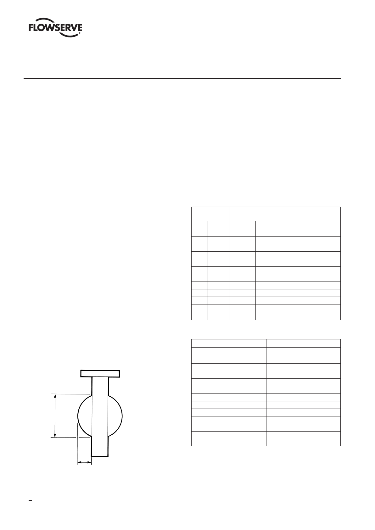
valve liner. Table 3 lists disc swing clearance requirements for mating pipe flanges. IMPORTANT – Fittings
such as tees and elbows cannot be bolted directly to the
valve. Spacers must be used.
3. Check the valve nameplate before installation to ensure
that the pressure rating and materials of construction
are compatible with the intended service conditions.
4. Inspect adjoining pipelines and remove any material that
could damage the valve liner.
5. Use flange gaskets to protect the valve liner during
installation.
6. Keep the valve in the closed position during all handling
and installation operations. This is necessary to protect
the disc sealing edge from damage and to ensure proper
positioning of the liner until the valve is installed.
7. Keep the valve liner clean. Any dirt or debris left in the
valve can scratch the liner or disc edge. Such damage
can impair the bubble tight shutoff provided by this
valve.
8. Do not allow the liner to catch on the mating pipe I.D.
and fold over. This will cause flange leakage and severe
damage to the liner.
9. While the BTV valve is bidirectional and will function
properly with the shaft orientation either vertical or
horizontal, the preferred orientation is with the shaft
horizontal and the disc lower edge opening downstream
for optimal service life.
10. Proper alignment of the valve in mating flanges is
required. This is especially true if oversize bolt holes
are used in piping flanges.
Flange bolts should be torqued to values listed in Table 4.
11.
12. After the valve has
been installed between
flanges and all
flange bolts have
been tightened, slowly
turn the disc and
check for freedom of
Disc Dimension
disc movement.
at Valve Face
13. If the valve is to be
removed from the
pipeline for any
reason, the
valve must be closed
Disc Projection
loosened. The valve must remain closed until removed
before any of the
flange bolts are
from the pipeline. SEE SAFETY PRECAUTIONS.
14. For recommended flange bolting sizes and lengths, refer
to Tables in Section XI and XII.
DO NOT run sharp instruments between the valve and liner
or between the liner and the pipe flanges. This practice will
result in severe liner damage.
TABLE 3
TABLE 4
Flange Bolting Torques
These are minimum torque values as established in Section
VIII of the ASME Boiler Code. Your piping practices,
materials and gaskets may dictate the use of torque values
greater than those listed. Refer to Section VIII of the ASME
Code for proper bolting torques.
VALVE DISC DISC DIM. AT
SIZE PROJECTION VALVE FACE
IN (MM) IN (MM) IN (MM)
2 (51) 0.390 (9.91) 1.805 (45.85)
3 (76) 0.672 (17.06) 2.586 (65.68)
4 (102) 0.994 (25.24) 3.487 (88.56)
6 (152) 1.860 (47.24) 5.510 (139.9)
8 (203) 2.688 (68.27) 7.379 (187.4)
10 (254) 3.626 (92.10) 9.569 (243.0)
12 (305) 4.438 (112.7) 11.564 (293.7)
14 (356) 5.071 (128.8) 12.758 (324.1)
16 (406) 5.626 (142.9) 14.718 (373.8)
18 (457) 6.407 (162.7) 16.719 (424.7)
20 (508) 7.157 (181.8) 18.656 (473.9)
24 (610) 7.781 (197.6) 20.750 (527.2)
VALVE SIZE TORQUE
in (mm) Ft.-Lbs. (Nm)
2 (51) 49 (66)
3 (76) 84 (114)
4 (102) 61 (83)
6 (152) 123 (167)
8 (203) 164 (222)
10 (254) 155 (210)
12 (305) 198 (268)
14 (356) 246 (334)
16 (406) 230 (312)
18 (457) 331 (449)
20 (508) 303 (411)
24 (610) 458 (620)
6
Page 7

SECTION III
DISASSEMBLY PROCEDURE
NOTE: BEFORE REMOVING THE VALVE FROM THE PIPE-
LINE, THE VALVE DISC MUST BE IN THE CLOSED POSITION
SO AS NOT TO DAMAGE THE SEALING EDGE OF THE DISC.
1. Place the valve in a vice or other suitable support. Do
not clamp on the face of the liner. Leave the disc in the
closed position during disassembly.
2. Remove the wrench, gear or actuator assembly from
the mounting plate.
3. Remove the mounting plate from the top of the valve by
removing two socket head screws.
4.
Loosen several turns but do not remove the retainer
plate screws on the top and bottom. CAUTION – Retainer
plates are under spring loading.
5. Loosen and remove the four bolts that hold the body
halves together.
6. Remove the top body half. Be careful not to lose the
body half bushings as they may drop out.
7. Remove the disc and liner assembly from the bottom
body half.
8. Complete the disassembly of top and bottom body
halves by removing the retainer plate screws, glands,
springs, bearings and stem seals.
9. CAREFULLY remove the disc from the liner. Use
extreme caution to avoid damaging the disc stem seal
convolutions or disc O.D. sealing surface. Once the liner
has been removed from the disc, it cannot be reused.
10. Clean and inspect all parts not contained in the repair kit
and replace if worn, damaged or heavily corroded.
11. If the disc is to be used again, carefully polish the
sealing edge of the disc to remove any scratches. Use
only 400 grit or finer sandpaper.
BTV/BUV 2000
SECTION IV
PARTS LIST
Indicates Repair Kit Parts
For 3” Only
Figure 3 - Exploded View of 2” and 3” Valves
7
Page 8

4”, 5” & 6”
Sizes Only
BTV/BUV 2000
Indicates Repair Kit Parts
Figure 4 - Exploded View of 4” - 16” Valves
For 20”, & 24”
Wafer and Lug
Body
For 20”, & 24” Only
Indicates Repair Kit Parts
Figure 5 - Exploded View of 18” - 24” Valves
8
Page 9

TABLE 5 - Bill of Materials
85
BTV/BUV 2000
Item Description
1 Body - (2 Piece) A395 GR. 60-40-18 A351-/A744 GR. CF8M 1 11111111111 1
1A Hex Head Cap Screw A193 GR. B7 A193 GR. B8* 4 444444444444
1B Hex Nut A194 GR. 2H A194 GR. 84444444444444
1C Body Bushing Carbon Steel 304 Stainless Steel 2 222222222222
2 Disc See Chart How to Specify See Chart How to Specify 1 111111111111
3 Retainer Plate Zinc Plated Carbon Steel 304 Stainless Steel 1 122222222222
4 Socket Head Cap Screw Zinc Plated A574-4037 Alloy Steel A193 GR. B8* 2 22222222222 2
4A Socket Head Cap Screw Zinc Plated A574-4037 Alloy Steel A193 GR. B8* 2 26666666666 6
5Top Gland 304 Stainless Steel 304 Stainless Steel 1 111111111111
5A I.D. O-Ring Viton Viton 1 111111111122
5B O.D. O-Ring Viton Viton 1 122222222222
6 Spring 302 Stainless Steel 302 Stainless Steel 1 122222222222
7 Bearing Glass-Filled Phenolic Glass-Filled Phenolic 1 122222222444
8 Stem Wedge Ring 302 Stainless Steel 302 Stainless Steel 1 122222222222
9 Stem Compression Ring Silicone or Viton Silicone or Viton 1 12222222222 2
10 Liner PTFE or UHMWPE PTFE or UHMWPE 1 11111111111 1
11 Seat Energizer Silicone or Viton Silicone or Viton 2 222222222222
12 Bottom Gland 304 Stainless Steel 304 Stainless Steel 1111111111 1
13 Actuator Mounting Plate Carbon Steel Nickel Plated Carbon Steel 1 11111111111 1
14 Stem Extension 304 Stainless Steel 304 Stainless Steel 111
15 Shim 303 Stainless Steel 303 Stainless Steel As Required
16 Disc Support Bracket Carbon Steel Carbon Steel 11
17 Disc Support Stud 304 Stainless Steel 304 Stainless Steel 11
18 Hex Nut A194 GR. 8 A194 GR.
19 Washer 303 Stainless Steel 303 Stainless Steel 22
20 Thrust Washer PTFE PTFE 22
21 Sleeve Carbon Steel 304 Stainless Steel 1
22 Ground Spring 300 Series Stainless 300 Series Stainless 1 111111111111
*Grade B8 fasteners must have 40,000 psi minimum yield strength.
Material of Construction Material of Construction
Standard Stainless
Quantity Required by Size
2 3456810 12 14 16 18 20 24
5
SECTION V
REPAIR KITS
IMPORTANT NOTE: The use of parts or repair tools other
than those supplied by the Flowserve Corpora tion could
adversely affect the operation and perfor mance of this
valve. Unauthorized modifications or substitution of
components could lead to premature valve failure due
to corrosion and/or functional problems with the
substituted parts.
Complete repair parts kits and repair tooling kits are available
from the Flowserve Corporation. Compo nents of the parts kits
are shown in Figures 3, 4, 5. Compo nents of the repair tooling
kits are shown in Figure 6.
IMPORTANT – Stem packing/bearing kits are calibrated to
a specific stack height. Top and bottom kits are packaged
separately. DO NOT MIX parts between kits.
Figure 6 - Repair Tools
9
Page 10

BTV/BUV 2000
Repair Tools
Item Description Use
1 Liner Stem Seal Die To re-form the liner stem seal around the disc stem prior to installing the disc-liner
assembly into the body.
2 Stem Seal Push Rod To push the stem seal components and bearings into position in the body stem bore.
3 Disc Stem Liner Guide To protect the liner stem seal and ease assembly of the disc into the liner.
4 Disc Stem Body Guide To guide the disc-liner assembly into the stem bore of each body half.*
*On the 14”-24” sizes, there are 2 Disc Stem Body Guides. The longest one is for the long disc stem, the shortest one is for the short disc stem.
SECTION VI
ASSEMBLY PROCEDURE
1. All Sizes
To assemble the disc (2) into the liner (10), first slide the
disc stem liner guide (repair tool item 3) over the long stem
of the disc. Then slide the long stem through either of the
liner stem seal necks (Figure 7). Push the liner down the
stem until it touches the edge of the disc.
Figure 7
2.
Sizes 2” - 8”
Rotate the disc 90 degrees (open position in the liner).
Using a vise, carefully squeeze the liner until the short
disc stem can slide through the other liner stem seal neck
(Figure 8). Exercise care to avoid gouging or damaging
the liner.
10
Figure 8
Sizes 10” - 24”
Clamp the long disc stem in a vise. Rotate the liner 90
degrees (disc open position) and by hand, squeeze the
liner until the short disc stem can slide into the other liner
stem seal neck (Figure 9). Exercise care to avoid gouging or
damaging the liner. This is a strenu ous operation especially
with UHMWPE liners. Heating the liner to 150° F prior to
attempting this operation will help. Two people may be
required to perform this operation on the larger sizes.
Page 11

Figure 9
3. All Sizes
Make sure the liner and disc are clean and then close the
disc into the liner to stretch the liner back into shape. Slide
the liner stem seal die (repair tool item 1) and push it up
tightly against the liner (Figure 10). Allow the dies to remain
in place for at least 5 minutes. Note that the end of the liner
stem seal die with the internal chamfer should be towards
the liner when installed.
Figure 10
BTV/BUV 2000
Figure 11
5.
Sizes 2” - 12”
Place the seat energizer (11) in the bottom body half
(Figure 12). Be sure that the energizer is firmly pushed
into the groove in the body. Also note the orientation of the
angled cuts on the ends of the energizer. When placing the
seat energizer into the top body half, the orientation of the
angled cuts must be opposite to the bottom half.
Figure 12
4. All Sizes
Clamp the bottom body half in a vise and place the body
bushings (1C) into the counterbored holes on diagonal
corners (Figure 11). Either body half can be used as top or
bottom, except for the 2” and 3”. On these sizes, the body
half with the blind stem bore is the bottom.
Sizes 14” - 24”
The seat energizers on these sizes must be trimmed to
length. Place the seat energizer in the bottom body half.
Be sure that the energizer is firmly pushed into the groove
in the body. Mark the seat energizer where it reaches the
machined end of the body half (Figure 13). Remove the seat
energizer and cut each end square at the mark. Place the
seat ener
pushed into the groove. The cut end of the seat energizer
should be flush to 1/16” above the machined end of the
body half.
gizer back into the groove being sure it is firmly
11
Page 12

Figure 13
BTV/BUV 2000
Size 20” and 24”
Prior to putting the liner-disc assembly into the body, the
disc support stud (17) must be attached to the short stem
of the disc. Thread one nut (18) on the short threaded end
of the stud all the way up to the flat on the stud. Apply a
thread locking material such as LOCKTITE® to the threads
on the short end of the stud and screw the stud into the
tapped hole on the short stem end of the disc. Torque the
stud to 100 ft-lbs, then tighten the nut against the disc stem
end to a torque of 100 ft-lbs.
6.
Size 2”
Spread the liner flanges apart and firmly push the linerdisc assembly into the lower body half.
Size 3”
Slide the liner stem sleeve (21) over the liner stem seal
neck on the short stem of the disc. Spread the liner flanges
apart and firmly push the liner-disc assembly into the lower
body half.
Sizes 4” - 24”
Remove the liner stem seal die from the short stem end
of the disc. Place the disc stem body guide (repair tool item
4) over the short stem of the disc (Figure 14). The end of
the disc stem body guide must cover the liner stem seal
neck for the tool to work properly. Spread the liner flanges
apart and carefully lower the liner-disc assembly into the
lower body half (Figure 15). Firmly push the liner-disc
assembly into the lower body half. Pull the disc stem body
guide off the short disc stem.
Figure 14
Figure 15
7.
Sizes 2” - 12”
Orient the top body half so that when put together with
the bottom half, the counterbored bolt holes will line up
with the body bushings (1C) in the bottom half. The DURCO
logo on the top body half should be on the opposite side of
the bottom half when bolted to gether. Firmly push the seat
energizer into the groove in the top body half. Orientate the
angled cuts on the ends of the energizers such that when
the body halves are bolted together, the ends on the top half
will mate with the bottom half. (Figure 16).
Figure 16
Sizes 14” - 24”
12
Page 13

BTV/BUV 2000
Trim the seat
energizers to length
per instructions in Step
6 and firmly push the
energizer into the
groove in the body.
8. All Sizes
Remove the liner
stem seal die from
the long stem of the disc.
Slide the disc stem
body guide (repair
tool item 4) over the
long stem making
sure that the end of
the body guide covers
the liner stem seal neck.
Orient the top body
half so that when put together with the bottom half, the
counterbored bolt holes will line up with the body bushings
(1C) in the bottom half.
half should be on the opposite side of the bottom half when
bolted together. Carefully lower the top body half over the disc
stem and push firmly in place (Figure 17). The gap between
the body halves should be approximately 1/4” when properly
assembled.
9. All Sizes
Install the four body bolts (1A) and finger tighten the nuts
(1B) maintaining an even gap between body halves (Figure
18). See note – Table 6.
10. All Sizes
There are two individually packaged stem packing kits
on all sizes (except for 2” and 3” which only have one).
The DURCO logo on the top body
Figure 17
Figure 18
top stem packing kit. This kit has a packing gland (5) with a
large hole bored through for the disc stem. Place the rubber
stem compression ring (9) into the top body stem bore with
the conical end facing upward, away from disc. Next place
the stem wedge ring (8) into the stem bore with the flat side
upward, away from the disc (Figure 19). The conical end
of the stem compression ring is designed to mate with the
conical bore in the wedge ring. Using the stem seal push
rod (repair tool item 2), push the compression ring and
wedge ring to the bottom of the body stem bore (Figure 20).
Figure 19
Figure 20
11. All Sizes
Next, place the bearing (7) over the disc stem and push
it into the body stem bore. Do not use excessive force to
prevent damage to the bearing. Using the stem seal push
rod, push the bearing to the bottom of the body stem bore.
If necessary, use a hammer and lightly tap on the stem seal
push rod to push the bearing into position. The 18” - 24”
sizes have two bearings. Install the second bearing in the
The packing sets are calibrated for stack height so it is
very important not to mix parts between kits. Locate the
same manner. Next place the metal shims (15) on top of
the bearing. Slide the spring (6) over the stem and into the
13
Page 14

bore. Take the larger diameter o-ring (5B) and put it into
the outside groove of the top gland (5). Place the smaller
diameter o-ring into the inside groove of the gland. Slide
the gland over the disc stem. The outside o-ring must be on
top, away from the disc (Figure 21). Place the ground spring
(22) over the disc stem.
Figure 21
BTV/BUV 2000
12. All Sizes
Place the retainer plate (3) over the disc stem on top of
the ground spring and gland. Find the two longest socket
head screws (4) and finger tighten them 3 to 4 turns into
diagonally opposite holes as follows: facing the valve body,
put one in the front hole on the left side of the body stem
bore and the other in the back hole on the right side. Put
two short socket screws (4A) in the other two holes and
finger tighten 3 to 4 turns (Figure 22). See note – Table 6.
Figure 22
13.
Sizes 4” - 6”
Turn the valve over and place the stem extension (14)
into the hole in the bottom disc stem. Install the stem
compression ring, stem wedge ring, bearing, shims, spring,
and bottom gland (12) with o-ring per the instructions in
steps 10,11 and 12. Note that the retainer plate screws on
the bottom are all the same length. See note – Table 6.
Sizes 8” - 18”
Turn the valve over and install the stem compres sion
ring, stem wedge ring, bearing, shims, spring, and bottom
gland (12) with o-ring per the instructions in steps 10, 11,
and 12. Note that the retainer plate screws on the bottom
are all the same length. See note – Table 6.
Size 20” and 24”
Turn the valve over and install the stem compres sion
ring, stem wedge ring, bearing, shims and spring per the
instructions in steps 10, 11 and 12. Place the small o-ring
(5B) in the groove on the inside bore and the large o-ring
in the groove on the outside of the bottom gland. Orient the
gland with the outside o-ring on top, away from the disc
and carefully slide the gland over the disc support stud.
Place the retainer plate on top of the gland. Next, thread 2
nuts (18) onto the disc support stud until they are touching
the retainer plate. Slide the metal washer (19) over the disc
support stud such that the recessed counterbore is facing
upwards, away from the disc. Next place the PTFE thrust
14
Page 15

BTV/BUV 2000
washer (20) on top of the metal washer. It should fit into
the counterbore of the metal washer. Place the disc support
bracket on next with the large center hole facing down,
towards the disc. Install 4 socket head screws and finger
tighten 3 to 4 turns (Figure 23). See note – Table 6.
Figure 23 - 20”
and 24”
Disc Support
Jam Nut
Bottom
Gland
Retainer
Plate
Disc
Support
Bracket
Disc
Support
Stud
Metal
Washer
PTFE
Thrust Washer
Outer
O-Ring
Inner
O-Ring
Retainer
Plate Bolt
Inner
Jam Nuts
Outer
Jam Nuts
Assembly Detail
14. All Sizes
Align the disc in the closed position so the disc is
centered in the liner. Close alignment is important so use
a scale to ensure the disc is closely centered. Measure at
the 3 o’clock and 9 o’clock positions (Figure 25). These
measurements will be identical with the disc properly
centered. In a criss-cross pattern, tighten the 4 body bolts
and torque to the values listed in Table 4. Be sure to bring
the body halves together evenly. This will require gradual
tightening of each bolt. As the body bolts are tightened,
the disc may rotate out of alignment with the seat. If this
occurs, stop tighten ing immediately, realign the disc in the
seat, and then continue tightening the bolts. Failure to bolt
the body halves evenly will cause them to bind. This may
pre vent the body halves from mating completely using
the specified bolting torques. DO NOT EXCEED TORQUE
SPECIFICATIONS ON BODY BOLTS. See note – Table 6.
15.
Sizes 4” - 12”
Tighten the 4 bottom retainer plate screws in a crisscross pattern and torque to the values listed in Table 6.
Be sure to bring the retainer plate down evenly. This will
require gradual tightening of each bolt. Failure to do so will
cause the bolts to bind on the retainer plate and may bend
the retainer plate. When properly in stalled, the retainer
plate will be tight against the body end. DO NOT EXCEED
TORQUE SPECIFICA TIONS ON RETAINER PLATE BOLTS.
See note – Table 6.
Sizes 14” - 18”
Check to make sure that the bottom gland is aligned
with the body stem bore. Tighten the 4 bottom retainer
plate screws in a criss-cross pattern and torque to the
values listed in Table 6. Be sure to bring the retainer plate
down evenly. This will require gradual tightening of each
bolt. Check to make sure that the bottom gland remains
aligned with the body stem bore. If not proper ly aligned,
the gland can bind in the stem bore and may bend the
retainer plate. When properly installed, the retainer plate will
be tight against the body end. DO NOT EXCEED TORQUE
SPECIFICA TIONS ON RETAINER PLATE BOLTS.
See note – Table 6.
TABLE 6 - Bolting Torques
Carbon Steel Fasteners
Part Body Body Retainer Retainer
Alloy B7 (8.8) 4037 (8.8)
Size Ft-Lbs (NM) Ft-Lbs (NM)
2 40 (54) 30 (41)
3 40 (54) 30 (41)
4 40 (54) 30 (41)
5 40 (54) 40 (54)
6 40 (54) 40 (54)
8 80 (108) 40 (54)
10 120 (163) 100 (136)
12 160 (217) 100 (136)
14 180 (244) 100 (136)
16 200 (271) 100 (136)
18 200 (271) 100 (136)
20 250 (339) 100 (136)
24 250 (339) 100 (136)
Stainless Steel Fasteners
Part Body Body Retainer Retainer
Alloy B8-40 (A2-70) B8-40 (A2-70)
Size Ft-Lbs (NM) Ft-Lbs (NM)
2 20 (41) 20 (41)
3 20 (41) 20 (41)
4 20 (41) 20 (41)
5 20 (41) 40 (54)
6 20 (41) 40 (54)
8 40 (54) 40 (54)
10 120 (81) 60 (81)
12 160 (81) 60 (81)
14 180 (163) 100 (136)
16 200 (217) 100 (136)
18 200 (217) 100 (136)
20 250 (339) 100 (136)
24 250 (339) 100 (136)
15
Page 16

BTV/BUV 2000
Important Note: For stainless steel or other high alloy
fasteners with a yield strength below 70,000 psi, it may
be necessary to use B7 fasteners for the initial assem bly.
Once the valve is fully assembled, each fastener must then
be removed one at a time and replaced with the high alloy
fastener. The high alloy fasteners must be torqued to the
levels specified in Table 6.
Size 20” and 24”
Check to make sure that the bottom gland is aligned with
the body stem bore. Tighten the 4 bottom retainer plate
screws in a criss-cross pattern and torque to the values
listed in Table 6. Be sure to bring the retainer plate down
evenly. This will require gradual tightening of each bolt.
Check to make sure that the bottom gland remains aligned
with the body stem bore. If not proper ly aligned, the gland
can bind in the stem bore and may bend the retainer plate.
Also, check to make sure that the jam nuts do not bottom
on the disc support bracket as the retainer screws are
tightened. It may be necessary to thread the nuts further
down on the disc support stud as the retainer screws are
tightened to maintain clearance. When properly installed,
the retainer plate will be tight against the body end. DO NOT
EXCEED TORQUE SPECIFICATIONS ON RETAINER PLATE
BOLTS. See note – Table 6.
After the retainer bolts are tightened, finger tighten the
inner jam nuts against the disc support bracket. Place the
outer PTFE thrust washer, the metal thrust washer with
the shallow counterbore facing down against the PTFE
washer, and 2 outer jam nuts on the disc support stud.
Finger tighten the jam nuts against the disc support bracket.
Using a wrench on the inner and outer jam nuts located
against the inner and outer metal washers, simultaneously
torque the nuts to approximately 40 ft-lbs. This will seat
the PTFE thrust washers against the bearing surface of
the disc support bracket. Then tighten the second jam nut
against the first jam nut to 100 ft-lbs. Make certain that when
tightening the second jam nut, the first jam nut or the disc
support stud does not turn. When complete, tack weld the
jam nuts together (Figure 23).
sealing edge of the disc or liner which will com pro mise the
bubble tight shutoff provided by this valve.
Figure 24
18. All Sizes
Align the disc in the closed position so that the disc is
centered in the liner. Close alignment is important so use
a scale to ensure the disc is closely centered. Measure at 3
o’clock and 9 o’clock positions. These measurements will
be identical with the disc properly centered (Figure 25). The
valve is now ready for the actuator to be installed.
16. All Sizes
Tighten the 4 top retainer plate screws following the
instructions in step 15. After all four screws are torqued to
the values listed in Table 6, remove the two longest retainer
screws (installed in step 5). Place the mount ing plate (13)
on top of the retainer plate, reinstall the two long retainer
screws (Figure 24) and torque to the values listed in Table
6. See note – Table 6.
17. All Sizes
Carefully clean all exposed liner surfaces. Cycle the valve
5 to 6 times making sure the disc swings com pletely through
the liner in both directions. The initial breaking torque will
be high. Cycling the disc several times helps to “set” the
liner and seat energizer plus smooth out any ridges that may
have formed in the liner during assembly. A small amount of
lubricant, such as silicon, applied to the disc sealing diameter
will help reduce the initial torque. BE CAREFUL to avoid dirt
or grit contamination in the liner as
16
this can scratch the
Figure 25
Page 17

SECTION VII
MANUAL GEAR OPERATOR INSTALLATION
BTV/BUV 2000
1. Close the valve. The flats on top of the stem should be
parallel with the valve flange face. NOTE: At this time
adjustments should be made to assure that the valve
body machined flanged surface (6) is parallel with the
disc. To accomplish this, place the valve body machined
flanged surface (6) on a level plate. Then position a
bubble level on the upper side of the shaft square and
adjust the shaft until com pletely level.
2. Rotate the gearbox handwheel (1) clockwise until the
gearbox pointer (2) indicates the “shut” position.
3. Place the gearbox on the valve mounting pad as shown in
Figure 26.
4. Loosen the gearbox stopping screws (3) and (7).
5. Install and tighten the gearbox bolts (4) with their
lockwashers.
6. Turn the gearbox closing stop screw (7) clockwise until it
stops, then tighten the lock nut (8).
7. Turn the gearbox handwheel (1) counterclockwise to
open the valve until the disc face is perpendicular to the
valve body flange face.
8. Turn the gearbox opening stop screw (3) clockwise until
it stops, then tighten the lock nut (5).
9. Cycle the valve from closed to open to closed again
using the gear operator. Recheck to make sure the disc
is centered on the seat by measuring the distance from
the machined surface on the disc edge to the inner edge
of the liner flanged surface (6) on the body. This should
be done at two points, at the 3 o’clock and 9 o’clock
positions. Both measurements should be equal.
Gearbox Stop
Screw (7)
Lock Nut (8)
Machined Flanged
Surfaced (6)
Body
Gearbox
Pointer (2)
Figure 26
Gearbox Stop
Screw (3)
Lock Nut (5)
Gearbox
Handwheel (1)
SECTION VIII
CHANGING MANUAL GEAR OPERATOR QUADRANTS
CAUTION: Do not attempt to change the manual gear
operator quadrant while the valve is in service.
1. Close the valve. The flats on top of the stem should be
parallel with the valve flange face. Depressurize system if
valve is installed as valve could open when manual gear
operator is removed.
2. Remove manual gear operator. Rotate the gearbox
handwheel (1) until the gearbox pointer (2) indicates the
“shut” position.
3. Place the gearbox on the valve mounting pad in the
desired quadrant.
4. Follow Steps 4 through 8 of the Manual Gear Operator
Installation instructions.
Mounting
Pad
Gearbox
Bolts (4)
17
Page 18

SECTION IX
LOCKING LEVER AND INDICATOR PLATE INSTALLATION
BTV/BUV 2000
1. Close the valve. The flats on top of the stem should be
parallel with the valve flange face. NOTE: At this time
adjustments should be made to assure that the valve
body machined flanged surface (5) is parallel with the
disc. To accomplish this, place the valve body machined
flanged surface (5) on a level plate. Then position a
bubble level on the upper side of the shaft square and
adjust the shaft until completely level.
2. Mount the indicator plate (1) to the valve as shown in
Figure 27 with the shakeproof washers placed between
the indicator plate (1) and the valve body mounting pad.
Do not tighten the indicator plate bolts (4) at this time.
3. Place the locking lever (2) on the valve stem as shown in
Figure 27. Tighten the pinch bolt (3) on the handle.
4. Position the indicator plate (1) so that the locking lever
fits in the “closed” position of the indicator plate (1).
Tighten the indicator plate bolts (4).
5. Cycle the valve from closed to open to closed again using
the locking lever handle. Recheck to make sure the disc
is centered on the seat by measuring the distance from
the machined surface on the disc edge to the inner edge
of the liner flanged surface (5) on the body. This should
be done at two points, at the 3 o’clock and 9 o’clock
positions. Both measurements should be equal.
Figure 27
Machined Flanged
Surface (5)
Body
Indicator Plate (1)
Pinch Bolt (3) Handle (2)
Indicator Plate Bolts (4)
SECTION X
CHANGING LOCKING LEVER QUADRANTS
CAUTION: Do not attempt to change locking lever handle
quadrants while the valve is in service.
1. Close the valve. The flats on top of the stem should be
parallel with the valve flange face. Depressurize system if
valve is installed as valve could open when locking lever
handle is removed.
2. Remove the locking lever (2) and indicator plate (1).
3. Mount the indicator plate (1) 180° from the position
shown in Figure 27. Do not tighten the indicator plate
bolts (4) at this time.
4. Follow Steps 3 and 4 in the Locking Lever and Indicator
Plate Installation instructions.
18
Indicator Plate
Bolts (4)
Locking
Lever
Page 19

SECTION XI
STUD BOLTS AND CAPSCREWS FOR INSTALLATION OF WAFER BODIES
Valve Size 18 20 24
Number of Stud Bolts 12 16 16
Dia. & Thread 11/8 - 8N 11/4 - 8N
“A” Length of Stud Bolts 103/4 111/2 13
Number of Capscrews 8 8 8
Dia. & Thread 11/8 - 8N 11/4 - 8N
“B” Length of Capscrews 3 3 3
Class 150#
ANSI B16.5
Flange Thickness
1
/8” Thick Gasket
“B”
“A”
BTV/BUV 2000
“B”
Valve Size 2 3 4 5 6 8 10 12 14 16
Number of Stud Bolts 4 4 8 8 8 8 12 12 12 16
Dia. & Thread
“A” Length of Stud Bolts 5 51/2 53/4 61/2 61/2 63/4 73/4 81/4 83/4 93/4
5
/8 - 11 UNC
3
/4 - 10 UNC
7
/8 - 9 UNC 1 - 8 UNC
SECTION XII
CAP SCREWS FOR INSTALLATION OF LUG BODIES
“A”
Class 150#
ANSI B16.5
Flange Thickness
“A”
1
/8” Thick Gasket
Valve Size 2 3 4 5 6 8 10 12 14 16 18 20 24
Number of Capscrews 8 8 16 16 16 16 24 24 24 32 32 40 40
5
Dia. & Thread
“A” Length of Capscrews 11/2 13/4 13/4 13/4 2 21/4 21/2 21/2 23/4 3 3 3 3
/8 - 11 UNC
3
/4 - 10 UNC
“A”
7
/8 - 9 UNC 1 - 8 UNC 11/8 - 8 11/4-8
“A”
19
Page 20

For more information, contact:
USA
Flowserve Corporation
Flow Control Division
1978 Foreman Drive
Cookeville, Tennessee 38501
Phone: 931 432 4021
Fax: 931 432 3105
Germany
Flowserve Ahaus GmbH
Flow Control Division
Von Braun Straße 19a
D-48683 Ahaus
Phone: +49 2561 686-100
Fax: +49 2561 686-200
FCD_Ahaus@Flowserve.com
FCD DVENIM0000-01 03.2013
For more information about the Corporation Flowserve,
visit: www.flowserve.com
Flowserve Corporation has established industry leadership in the design and manufacture of its products. When properly selected, this Flowserve
product is designed to perform its intended function safely during its useful life. However, the purchaser or user of Flowserve products should be
aware that Flowserve products might be used in numerous applications under a wide variety of industrial service conditions. Although Flowserve
can (and often does) provide general guidelines, it cannot provide specific data and warnings for all possible applications. The purchaser/user
must therefore assume the ultimate responsibility for the proper sizing and selection, installation, operation, and maintenance of Flowserve
products. The purchaser/user should read and understand the Installation and Maintenance (I & M) instructions included with the product, and
train its employees and contractors in the safe use of Flowserve products in connection with the specific application.
While the information and specifications contained in this literature are believed to be accurate, they are supplied for informative purposes only
and should not be considered certified or as a guarantee of satisfactory results by reliance thereon. Nothing contained herein is to be construed
as a warranty or guarantee, express or implied, regarding any matter with respect to this product. Because Flowserve is continually improving and
upgrading its product design, the specifications, dimensions and information contained herein are subject to change without notice. Should any
question arise concerning these provisions, the purchaser/user should contact Flowserve Corporation at any one of its worldwide operations
or offices.
Singapore
Flowserve Pte. Ltd.
12 Tuas Avenue 20
Republic of Singapore 638824
Phone: 65 862 3332
Fax: 65 862 2800
www.owserve.com
 Loading...