

Page 1

BK 212
Installation Instructions 810609-00
Steam Trap BK 212
1
Page 2
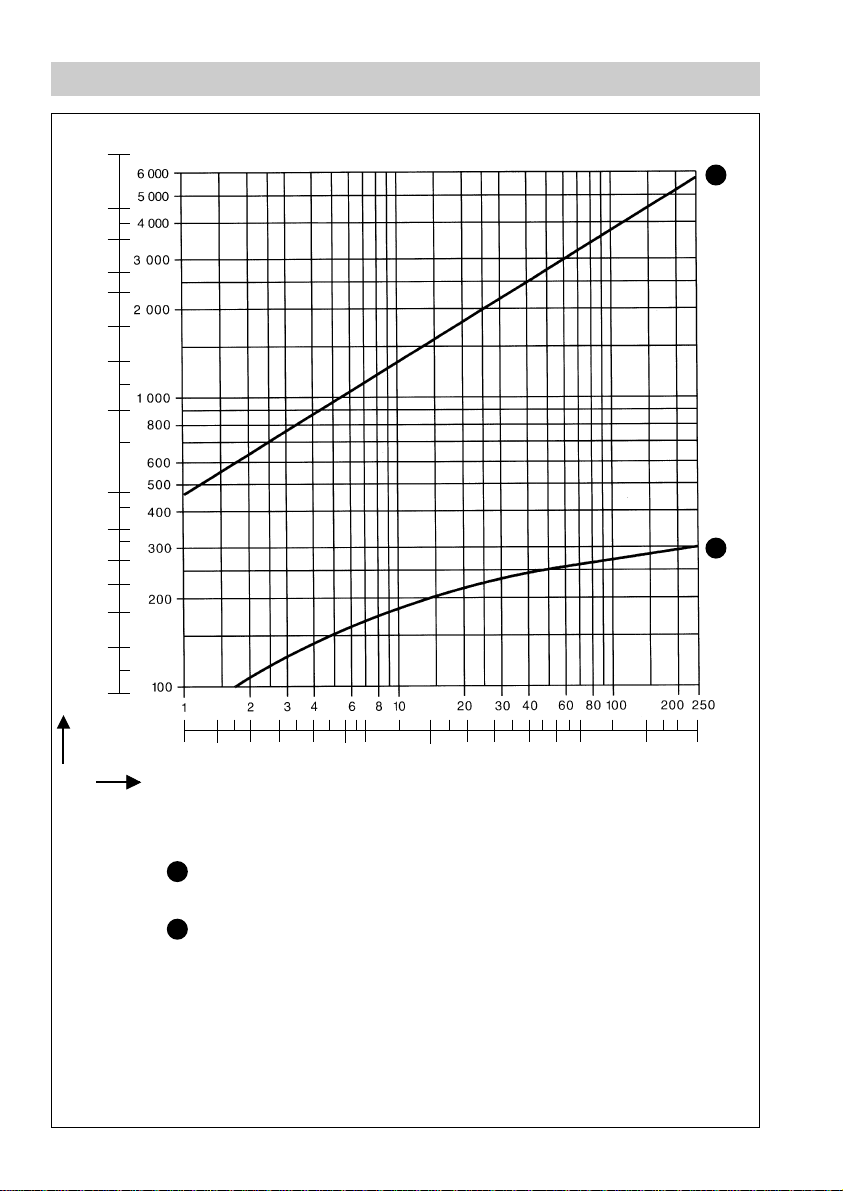
Capacity Chart
[lb/h] [kg/h]
15000
10000
8000
6000
5000
4000
3000
2000
1000
2
800
600
500
400
300
Capacity
200
Fig. 1
15 20 30 40 60 80 100 200 300 400 600 800 1000 2000 3000 3625 [psi]
Differential pressure ∆PMX (assuming discharge to atmospheric pressure)
Max. capacity of hot condensate at factory
1
setting and steam-tight shut-off
2
Max. capacity of cold condensate
1
[bar]
2
Page 3
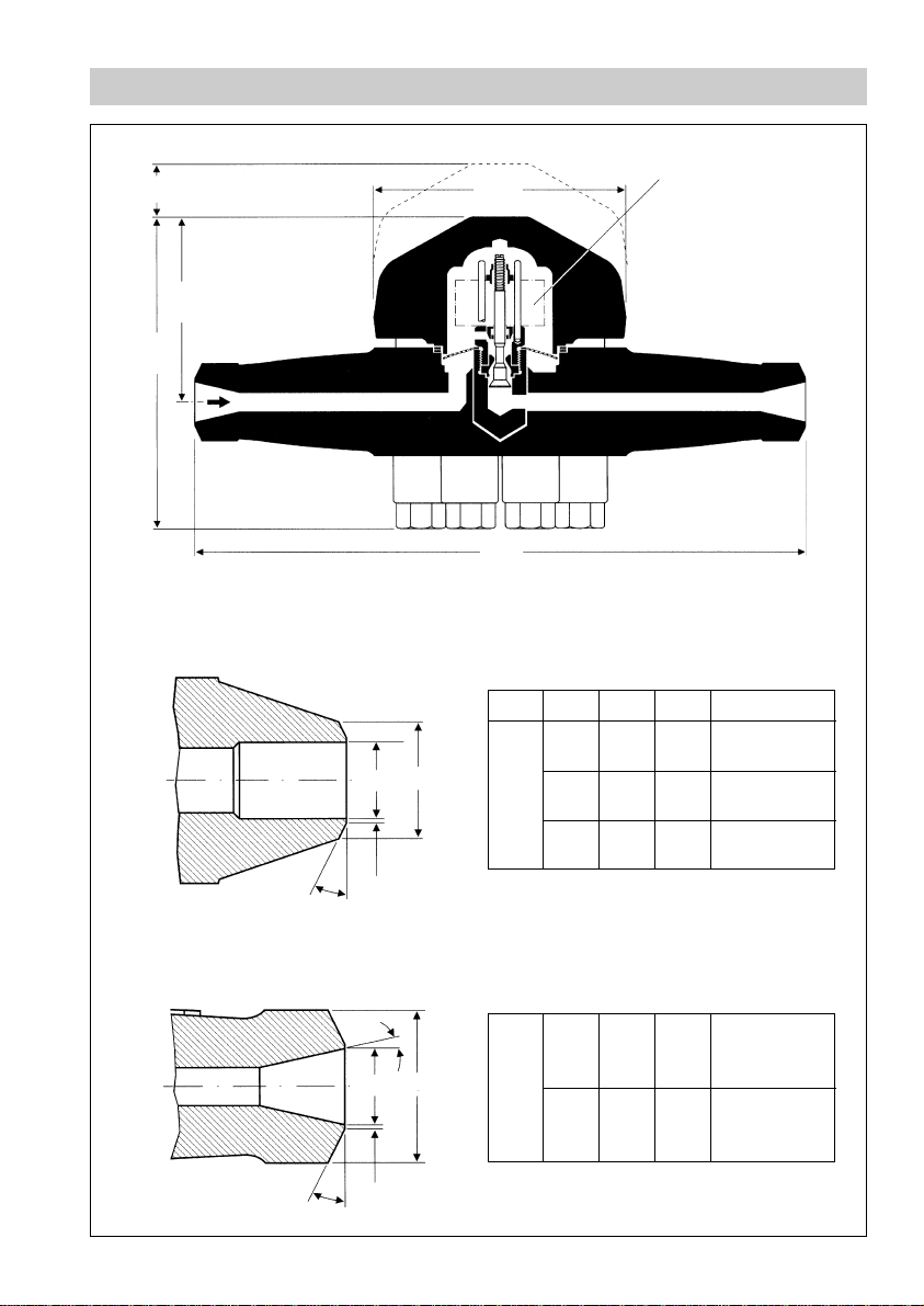
Dimensions
150
Space required
for opening trap
102
~
~
182
~
~
Fig. 1
Butt-weld ends according to DIN 3239-1-R6
edge form 22 to DIN 2559
∅ 140
330
Temperature feeler of
Duo stainless steel plates
2
d1d
1.5
Fig. 2
30°
Butt-weld ends according to DIN 3239-2-R8
edge form 22 to DIN 2559
12°
2
d1d
1.5
Fig. 3
30°
DN d
d
1
2
15 15 22 21.3x3.2
20 19 28 26.9x4.0
PN 320
25 24 35 33.7x5.0
DIN 3239-1-R6
15 18.5 34 33.7x8.0
PN 630
25 25 49 48.3x12.5
DIN 3239-2-R8
for pipe
3
Page 4
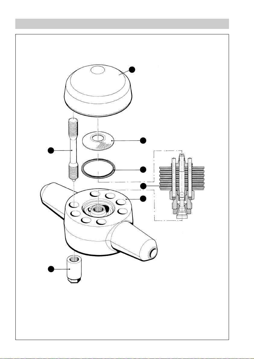
Parts Drawings
G
A
B
C
D
E
4
F
Fig. 4
Page 5

Key
A
Cover
B
Strainer
C
Gasket
D
Regulator
E
Body
F
Cap nut
G
Cover bolt
10
5
Page 6

Contents
Page
Important Notes
Safety note ...................................................................................................................... 7
Danger ............................................................................................................................ 7
Explanatory Notes
Scope of supply .............................................................................................................. 8
Description ...................................................................................................................... 8
Function .......................................................................................................................... 8
Technical data ........................................................................................................... 9-10
Installation
BK 212 ........................................................................................................................... 10
Heat treatment of welds ............................................................................................... 10
Regulator ......................................................................................................................11
Maintenance
Replacing of regulator................................................................................................... 11
Spare Parts List
Spare parts ................................................................................................................... 12
6
Page 7

Important Notes
Safety Note
Use steam trap BK 212 only for the discharge of steam condensate. The steam trap
may only be installed by qualified staff. Qualified staff are those persons who – through
adequate training in engineering, the use and application of equipment in accordance
with regulations concerning steam systems, and first aid & accident prevention – have
achieved a recognised level of competence appropriate to the installation and
commissioning of this device.
Danger
The steam trap is under pressure when the system is operating.
When loosening flanged connections or plugs hot water or steam may
escape. This presents the risk of severe scalds to the whole body.
Before carrying out installation and maintenance work it is therefore
essential to isolate and depressurize the trap.
The trap becomes hot during operation.
This presents the risk of severe burns to hands and arms.
Before carrying out any installation or maintenance work make sure that
the trap is cold.
Sharp edges on internals present a danger of cuts to hands.
Always wear industrial gloves when replacing the regulator.
7
Page 8

Explanatory Notes
Scope of Supply
BK 212
1 Steam trap type BK 212
1 Installation manual
Description
Thermostatic/thermodynamic steam trap with corrosion-resistant regulator unaffected
by waterhammer. The trap features:
■
Integral strainer
■
Non-return valve action
■
Asbestos-free cover gasket (graphite/1.4541)
■
Installation in any position
Function
The BK 212 is a thermostatic/thermodynamic steam trap with corrosion-resistant Duo
S. S. regulator unaffected by waterhammer. The trap opens and closes irrespectively
of the temperature and pressure prevailing inside the trap. The BK 212 vents air
automatically at start-up and during continuous operation.
8
Page 9

Technical Data
Pressure/Temperature Rating for standard equipment
TMA (admissible temperature) in [°C] for butt-weld ends
to DIN 3239
PMA
(allowable pressure)
[bar] [psi] 15 (
Form 1 – R6 Form 2 – R8
DN [mm] (in) DN [mm] (in)
1
/2") 20*) (3/4") 25 (1") 15 (1/2") 25 (1")
105 1523 550 550 550 550 550
121 1755 540 550 550 550 550
123 1784 539 549 550 550 550
150 2175 525 535 536 550 550
180 2610 511 521 523 550 550
211 3060 500 509 511 550 550
225 3263 494 505 506 546 550
250 3625 485 497 499 538 542
275 3988 476 487 490 531 535
300 4350 467 481 484 525 528
∆PMX (max. differential pressure) 250 bar (3625 psi)
(inlet pressure minus outlet pressure)
Pressure/Temperature Rating for special design (with special bolts and nuts)
TMA (admissible temperature) in [°C] for butt-weld ends
to DIN 3239
PMA
(allowable pressure)
[bar] [psi] 15 (
167 0972 580 580 580 580 580
178 1131 571 580 580 580 580
180 1160 569 579 580 580 580
110 1595 546 556 557 580 580
137 1987 532 541 542 580 580
144 2088 528 538 539 577 580
162 2350 519 529 530 569 580
180 2610 511 521 523 560 573
200 2900 504 513 515 554 565
225 3263 494 505 506 546 557
250 3625 485 497 499 538 550
275 3988 476 487 490 531 543
300 4350 467 481 484 525 537
*) DN 20 not covered by DIN standards.
Form 1 – R6 Form 2 – R8
DN [mm] (in) DN [mm] (in)
1
/2") 20*) (3/4") 25 (1") 15 (1/2") 25 (1")
9
Page 10

Technical Data – continued –
Materials DIN reference
Body 10CrMo 9 10 (1.7380)
Cover bolts (standard) 21 CrMoV 5 7 (1.7709)
Nuts (standard) 24 CrMo 5 (1.7258)
Special cover bolts and nuts X 22 CrMoV 12 1 (1.4923)
Regulator Corrosion-resistant Duo stainless steel
sealing surfaces:
wear-resistant titanium alloy
Other internals Stainless steel
Installation
BK 212
1. The steam trap BK 212 can be installed in any position. In the case of a horizontal
installation, make sure that the cover is at the top.
2. Take care of flow direction. The flow arrow is on the trap body.
3. Consider space required for opening trap. When the trap is installed a minimum
space of 150 mm is required for removing the cover .
4. Remove plastic plugs. They are only used as transit protection.
5. Clean socket-weld ends.
6. Arc-weld trap only manually (welding process 111 in accordance with
DIN EN 24063).
A
Attention
■
Only qualified welders certified e. g. according to DIN EN 287 may weld
the steam trap into pressurized lines.
■
Do not insulate the steam trap.
Heat T reatment of Welds
After the steam trap has been welded into the pipeline the welds require special heat
treatment (we recommend resistance annealing according to DIN EN 100529).
Remove the regulator before carrying out the heat treatment (see Maintenance).
Annealing must be restricted to the region of the welds.
10
Page 11

Installation – continued –
Regulator
The regulator is set at our factory to close steam-tight and open as soon as
condensate is formed.
Tools
■
Spanners A.F. 24 mm
Maintenance
The BK 212 does not require any special maintenance. However, if used in new
installations which have not been rinsed it may be necessary to check and clean the
trap.
Replacing Regulator
11.Remove cover from body , Fig. 4
12.Undo regulator using a spanner.
13.Unscrew regulator and take off strainer .
A E
D
D
B
14.Clean body, regulator, cover and strainer.
15.Clean gasket seating surfaces and insert new gasket .
16.Clean sealing surfaces of regulator and body .
17.Replace strainer .
18.Screw in regulator and tighten with a torque of 100 Nm.
19.Apply heat-resistant lubricant to threads of cover bolts (use for instance
MOLYKOTE HSC
10.Replace cover . Insert bolts and tighten cap nuts at room temperature in
B
D
+®
)
A G F
C
ED
G
diagonally opposite pairs with a torque of 225 Nm.
Tools
■
Spanner A.F. 24 mm
■
Torque spanner 20–120 Nm to DIN ISO 6789
MOLYKOTE® is a registered trademark of Dow Corning GmbH, Wiesbaden
11
Page 12

Spare Parts
Fig. 5
Spare Parts List
Item no. Designation Ref. no.
2 Regulator, complete, including
D
C
4.1 Gasket (graphite/1.7335) 374009
B
4.2 Strainer 096345
cover gasket (item 4.2)
C
D
B
C
371862
12
Page 13

13
Page 14

GESTRA Gesellschaften · GESTRA Companies · Sociétés GESTRA · Sociedades Gestra · Società GESTRA
GESTRA Gesellschaften · GESTRA Companies · Sociétés GESTRA · Sociedades Gestra · Società GESTRA
Vertretungen weltweit · Agencies all over the world · Représentations dans le monde entier · Representaciones en todo el mundo · Agenzie in tutto il mondo
Vertretungen weltweit · Agencies all over the world · Représentations dans le monde entier · Representaciones en todo el mundo · Agenzie in tutto il mondo
España
España
GESTRA ESPAÑOLA S.A.
GESTRA ESPAÑOLA S.A.
Luis Cabrera, 86-88
Luis Cabrera, 86-88
E-28002 Madrid
E-28002 Madrid
Tel. (091) 5 152 032
Tel. 003491/5152032
Fax (091) 4 136747; (091) 5 152 036
Fa x003491/41 3674 7; 51 52036
E-mail: gestra@gestra.es
E-mail: gestra@gestra.es
France Portugal
France Portugal
Invensys Flow Control
Flowserve Flow Control S.A.S.
France SAS
10 Avenue du Centaure, BP 8263
10 Avenue du Centaure, BP 8263
F-95801 CERGY PONTOISE CEDEX
F-95801 CERGY PONTOISE
Tél. 0 0331/34432660
Tél. (01) 34.43.26.60
Fax 00331/34432687
Fax (01) 34.43.26.87
E-mail: gnation@flowserve.com
E-mail: gnation@gestra.fr
Italia
Italia
Invensys Flow Control Division
Italgestra S.r.l.
Italgestra S.r.l.
Via Carducci 125
Via Carducci 125
l-20099 Sesto San Giovanni (MI)
l-20099 S.S. Giovanni (MI)
Tel. 003902/241012.1
Tel. (02) 24 10 121
Fax 003902/241012.460
Fax (02) 24 10 12460
E-mail: info@italgestra.it
E-mail: info@italgestra.it
Polska
Polska
GESTRA POLONIA Spolka z o. o.
GESTRA POLONIA Spolka zo.o.
Ul. Schuberta 104
Ul. Schuberta 104, P. O. Box 71
PL-80-172 Gdansk
PL-80-172 Gdansk
Tel. (058) 306 1002
Tel. 004858/3061002 oder 306 1010
Fax (058) 306 10 03
Fax 004858/3061003 oder 306 3300
E-mail: gestra@gestra.pl
E-mail: gestra@gestra.pl
GESTRA PORTUGUESA VALVULAS LDA.
GESTRA PORTUGUESA VALVULAS LDA.
Av. Dr. Antunes Guimarães, 1159
Av. Dr. Antunes Guimarães, 1159
P-4100 Porto
Porto 4100-082
Tel. (022) 6 19 87 70
Tel. 0035122/6 19 8770
Fax (022) 6 10 7575
Fax 0035122 /6 107575
E-mail: gestra@gestra.pt
E-mail: gestra@gestra.pt
®
®
GESTRA GmbH
GESTRA GmbH
Postfach 10 54 60
Postfach 10 54 6 0
D-28054 Bremen
D-28054 Bremen
Hemmstraße 130
Münchener Str. 77
D-28215 Bremen
D-28215 Bremen
Tel. + 49 (0) 421 35 03-0
Tel. +49 (0) 421 35 03-0
Fax +49 (0) 421 35 03-393
Fax+49 (0) 421 35 03-393
E-mail
gestra.gmbh@gestra.de
E-mail
gestra.gmbh@gestra.de
Internet www.gestra.de
Internet www.gestra.de
A Unit of Flowserve Corporation
An Invensys company
810609-00/1100c · ©1999 GESTRA GmbH · Bremen · Printed in Germany
14
 Loading...