

Page 1

WARMING DRAWER
WB60S models
INSTALLATION GUIDE
NZ AU GB IE
59051F 09.17
Page 2
1 SAFETY AND WARNINGS
!
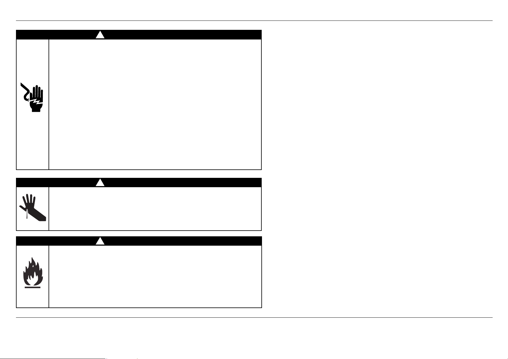
WARNING!
Electrical Shock Hazard
Before carrying out any work on the
electrical section of the appliance,
it must be disconnected from the
mains electricity supply.
Connection to a good earth wiring
system is absolutely essential and
mandatory.
Alterations to the domestic wiring
system must only be made by a
qualified electrician.
Failure to follow this advice may
result in electrical shock or death.
!
WARNING!
Cut Hazard
Take care - panel edges are sharp.
Failure to use caution could result in
injury or cuts.
!
WARNING!
Fire hazard
Do not use adapters, reducers, or
branching devices to connect this
appliance to the mains power supply.
Failure to follow this advice may
result in overheating, burning, or fire.
IMPORTANT SAFETY INSTRUCTIONS!
●
To reduce the risk of fire, electrical
shock, injury to person, or damage
when using the warming drawer,
please read these instructions
carefully before installing this product.
●
Please make this information available
to the person installing the product –
doing so may reduce your installation
costs.
●
Installation work, maintenance and
repairs may only be carried out by
suitably qualified and competent
persons in accordance with national
and local safety regulations.
●
Always disconnect the power supply
prior to carrying out any installation,
maintenance or repair work.
●
Before installation make sure that
the voltage and frequency listed on
the data plate corresponds with the
household electrical supply.
IMPORTANT!
SAVE THESE INSTRUCTIONS
The models shown in this installation guide may not be available in all markets and are subject to change at any time. For current details about model and specification availability in your country, please go to our
website www.fisherpaykel.com or contact your local Fisher & Paykel dealer.
1
Page 3

1 SAFETY AND WARNINGS
IMPORTANT SAFETY INSTRUCTIONS!
●
The electrical outlet should be easily
accessible after installation.
●
When a companion product is installed
in combination with the warming drawer
to the same circuit, operating both
products may cause an overload. If in
doubt consult a qualified electrician.
●
When installed in combination with
a companion product the companion
product may be placed directly onto
the warming drawer. It is not necessary
to place a shelf between the products.
A built- in shelf at the base of the
cabinetry able to support the weight of
both products is required.
●
If installing the warming drawer directly
underneath an oven, ensure you do
not damage the oven’s lower trim. The
lower trim ensures correct air circulation
to the oven and allows the door to
open and close without obstruction.
Fisher & Paykel does not accept any
responsibility for any damage resulting
from incorrect installation.
●
The maximum weight the warming
drawer is able to support is 60 kg.
●
The warming drawer is not designed
for use in mobile installations such as
recreational vehicles, boats or aircraft.
●
When installing companion products
the weight of the companion product
should be distributed across the edges
of the warming drawer. Products
above which rest on “feet” may only
be installed if the feet of the product
lie within 70mm of the sides of
the warming drawer, as this area is
reinforced. Failure to do this may result
in damage to the warming drawer and
companion product.
●
Before installing the warming drawer
you must inspect it for any signs of
damage. Under no circumstances
should you install or use the warming
drawer if it has been damaged.
●
If the power supply cord is damaged, it
must be replaced by the manufacturer,
its service agent or a similarly qualified
tradesperson in order to avoid a hazard.
●
Connect the warming drawer to a
properly rated, protected and sized
power supply circuit to avoid electrical
overload.
●
Do not use an extension cord or a
portable electrical outlet device (e.g.
multi-socket outlet box) to connect the
Warming Drawer to the power supply.
Make sure the power supply cord is
located so that it will not be stepped
on, tripped over or otherwise subject to
damage or stress.
●
Ensure the connection to power supply
is accessible after installation.
2
Page 4
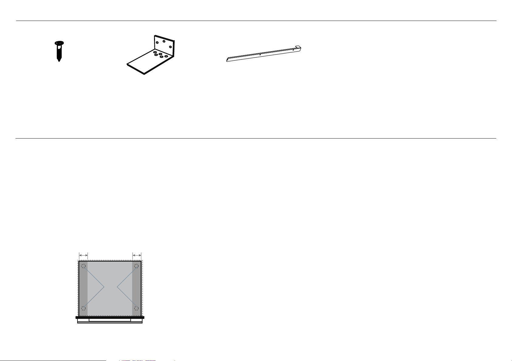
2 PARTS SUPPLIED
Screws (4) Anti-tip bracket (1) Oven support brackets (2)
3 PRIOR TO INSTALLATION
●
The cavity is square and level, and of the required dimensions.
●
The installation will comply with all clearance requirements and applicable standards and regulations.
●
The power switch will be easily accessible to the customer when the warming drawer is installed.
●
The warming drawer (and any product on top of it) will rest on a surface that can support its weight.
●
The height from the floor suits the customer.
●
You consult local building authorities and by-laws if in doubt regarding installation.
If installing with a companion product
IMPORTANT!
●
If installing with a companion product please refer to the installation instructions of that product to ensure the installation requirements of BOTH products are met.
●
When installing products on top of the warming drawer, the weight of the product should be distributed across the edges of the warming drawer.
●
Products above which rest on “feet” may only be installed if the feet of the product lie within 70mm of the sides of the warming drawer, as this area is reinforced.
Failure to do this may result in damage to the warming drawer and companion product.
70mm 70mm
Feet
3
Warming Drawer can withstand
a maximum weight of 60kg
Page 5
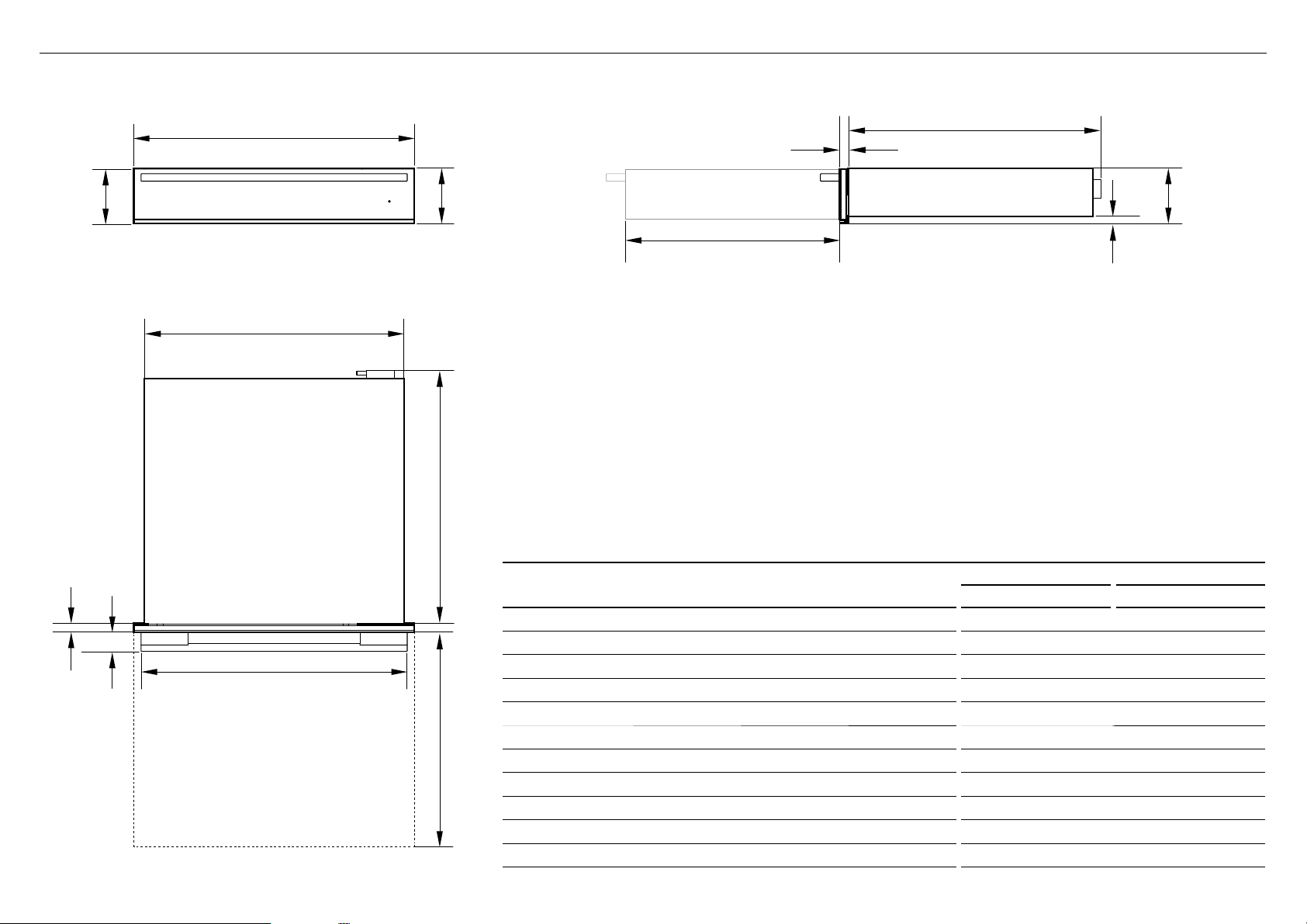
4 PRODUCT DIMENSIONS
I
B
FRONT
E
Terminal Block
A
D
H
C
D
SIDE
F
G
C
J
K
PLAN
H
PRODUCT DIMENSIONS
Overall height of product 118 118
A
Overall width of product 596 596
B
Depth of drawer front panel (excluding handle)* 20 22
C
Depth of chassis (including terminal block) 536 536
D
Width of chassis at rear 551 551
E
Height from bottom drawer panel to bottom of chassis at rear 16 16
F
Height from bottom of drawer panel to top of chassis 118 118
G
Depth of drawer (open) (measured from front of drawer) 455 455
H
Height of drawer front panel 116 116
I
Depth of handle measured from front of drawer 41 41
J
Width of handle 565 565
K
WB60SDEB WB60SDEX
mm mm
4
Page 6

THE FOLLOWING PAGES DETAIL COMMON CABINETRY SCENARIOS
5A CABINETRY DIMENSIONS - UNDERBENCH (IE INSTALLED WITH A F&P 60CM WIDE SINGLE OVEN)
N
**
720mm
CABINETRY DIMENSIONS mm
Minimum inside height of cavity (with F&P 60cm wide single oven) 687
M
Inside width of cavity 560
N
Minimum inside depth of cavity 565
O
Note: When installed in combination with a companion product the companion product may be placed directly onto the
warming drawer. It is not necessary to place a shelf between the products. A built- in shelf at the base of the cabinetry able
to support the weight of both products is required.
* PO - POWER OUTLET. Ensure there is an accessible earthed power outlet within 900mm of the centre rear of the product.
** In some instances the front cabinetry rail may need to be removed to enable installation.
Oven
Warming Drawer
M
Warming Drawer
5
Oven
SIDE
*PO
O
Fit the supplied oven support brackets
Oven
support
brackets
PLAN
Ta b
Unscrew-fitrescrew
Oven support bracket
IMPORTANT!
If installing under an oven, you must first fit the two
supplied Oven support brackets to the sides of the
Warming Drawer. The brackets help support the rear of
the oven.
Unscrew the 3 top screws on each side, fit the brackets
with the tabs facing inwards as shown and screw back in.
Note: The screws may not be identical.
Replace each screw into its original hole position.
Page 7

5B CABINETRY DIMENSIONS - WALL MOUNTED (IE INSTALLED WITH A F&P COMPACT OVEN)
N
Compact Oven
M
600mm
Compact Oven
Warming Drawer
Warming Drawer
M
CABINETRY DIMENSIONS mm
Minimum inside height of cavity
M
with optional Lower trim kit fitted
without optional Lower trim kit fitted
Inside width of cavity 560
N
Minimum inside depth of cavity 565
O
590
570
SIDE
O
*PO
Compact oven
Lower trim kit
(optional, supplied separately)
Warming Drawer
Additional 18 mm Wood Spacer
Cabinet below
PLAN
IMPORTANT!
In a wall mounted installation,
there needs to be an 18 mm
Spacer fixed underneath the
warming drawer first to raise
it to the required height.
Note: When installed in combination with a companion product the companion product may be placed directly onto the
warming drawer. It is not necessary to place a shelf between the products. A built- in shelf at the base of the cabinetry able
to support the weight of both products is required.
* PO - POWER OUTLET. Ensure there is an accessible earthed power outlet within 900mm of the centre rear of the product.
6
Page 8

5C CABINETRY DIMENSIONS - WALL MOUNTED (IE INSTALLED WITH A F&P COFFEE MAKER)
IMPORTANT!
If installing under the F&P Coffee Maker, ensure there
is the 45mm gap at the back of the cabinet and the
200mm2 toekick cutout required for airflow.
Refer to the Coffee Maker Install instructions.
N
45mm
Anti-tip Bracket
Coffee Maker
M
600mm
CABINETRY DIMENSIONS mm
Minimum inside height of cavity
M
with optional Lower trim kit fitted
without optional Lower trim kit fitted
Inside width of cavity 560
N
Minimum inside depth of cavity 565
O
Coffee Maker
Warming Drawer
Coffee Maker
Side rail
Lower trim kit
(optional, supplied separately)
Warming Drawer
Warming Drawer
SIDE
590
570
O
*PO
Supplied Anti-tip Bracket
(screwed to the back wall)
M
Additional 18mm Wood Spacer
PLAN
IMPORTANT!
When installing under an F&P Coffee Maker
you must ensure the supplied anti-tip
bracket is installed, unless there is a fixed
shelf above the drawer acting as an anti-tip
obstacle.
IMPORTANT!
In a wall mounted installation,
there needs to be an 18mm
Spacer fixed underneath the
warming drawer first to raise
it to the required height.
Note: When installed in combination with a companion product the companion product may be placed directly onto the
warming drawer. It is not necessary to place a shelf between the products. A built- in shelf at the base of the cabinetry able
to support the weight of both products is required.
* PO - POWER OUTLET. Ensure there is an accessible earthed power outlet within 900mm of the centre rear of the product.
7
Page 9

5D CABINETRY DIMENSIONS - WALL MOUNTED (STANDALONE)
Supplied Anti-tip Bracket
(screwed to the back wall)
IMPORTANT!
In a standalone wall mounted installation, you
must ensure that the supplied anti-tip bracket
is installed unless there is a fixed shelf above
acting as an anti-tip obstacle.
N
M
Steam Oven
Warming Drawer
CABINETRY DIMENSIONS mm
Inside height of cavity
M
Inside width of cavity 560
N
Minimum inside depth of cavity 545
O
120mm
SIDE
120
Fixed shelf
*PO
O
Cabinet above
Warming Drawer
Additional 18mm Wood Spacer
Cabinet below
PLAN
IMPORTANT!
In a wall mounted
installation, there needs
to be an 18mm Spacer
fixed underneath the
warming drawer first to
raise it to the required
height.
* PO - POWER OUTLET. Ensure there is an accessible earthed power outlet within 900mm of the centre rear of the product.
8
Page 10

6 DISCARD PACKAGING RESPONSIBLY
Unpack the warming drawer and inspect for any signs of damage.
Do not install the warming drawer if it has been damaged.
IMPORTANT!
Packing materials (e.g. plastic bags, polystyrene foam, staples,
packing straps etc) and tools should not be left around during
and after installation, especially if they are within easy reach of
children, as they may cause serious injuries.
7 MARK AND PRE-DRILL THE HOLES FOR SECURING THE WARMING DRAWER
IMPORTANT!
Do not lift the warming drawer by the drawer handle.
Recycle responsibly
8 CONNECT THE WARMING DRAWER TO THE MAINS SUPPLY
IMPORTANT!
●
All electrical work may only be carried out by suitably qualified and competent persons in accordance with national and
local safety regulations.
●
This warming drawer must be earthed.
Before placing the warming drawer into the cavity, route the power cord into the back of the cavity and plug it in to the
switched socket. The switched socket should be in an easily accessible area within 900mm of the centre rear of the product.
Power requirements
Model Code Power Voltage Wattage
WB60S 1.6 - 1.8 A 220-240 V 360-420W
9
Page 11

9 SECURE THE WARMING DRAWER TO THE CABINETRY
1 Ensure the warming drawer is level and positioned in place in the cavity.
IMPORTANT!
Do not lift the warming drawer by the drawer handle.
2 Fully open the drawer.
3 Fasten the warming drawer in place with the two screws supplied, through the
front trim, beneath the drawer. Do not overtighten the screws.
!0 SECURE THE ANTI-TIP BRACKET (OPTIONAL DEPENDING ON CABINETRY CONFIGURATION)
If the anti-tip bracket is required (see example scenarios) first secure the product at the
front, then place the bracket centrally at the back of the cavity, sitting it on the top of
the chassis. Secure it to the rear cabinet wall using the screws provided.
10
Page 12

!1 FINAL CHECKLIST
TO BE COMPLETED BY THE INSTALLER
Make sure the warming drawer is level and securely fitted to the cabinetry.
Make sure any internal packaging has been removed from the drawer.
Make sure that the isolating switch is accessible by the customer.
Make sure the anti-tip bracket has been fitted correctly if it is required.
If installing an oven directly on top of the warming drawer, make sure the supplied oven
support brackets have been fitted to the warming drawer.
TEST OPERATION:
Open the drawer and press the
The on/off halo and temperature setting 2 ( ) halo should glow red.
Shut the drawer.
After 5-10 minutes open the drawer. The internal surfaces of the drawer should feel
slightly warmed.
Press the button to turn the warming drawer off and shut the drawer.
Complete and keep for safe reference:
Model
Serial No.
Purchase Date
Purchaser
Dealer Address
button to turn the warming drawer on.
Installer’s Name
Installer’s Signature
Installation Company
Installation Date
11
Page 13

12
Page 14

Page 15

Page 16

FISHERPAYKEL.COM
© Fisher & Paykel Appliances 2017. All rights reserved.
The product specifications in this booklet apply to the specific products
and models described at the date of issue. Under our policy of continuous
product improvement, these specifications may change at any time. You
should therefore check with your Dealer to ensure this booklet correctly
describes the product currently available.
NZ AU GB IE
59051F 09.17
 Loading...