

Fisher & Paykel RDV2-486GD, RGV2-486GL, RDV2-486GL, RGV2-485GD, RDV2-485GD Installation Manual
...
PROFESSIONAL RANGE
RDV2 & RGV2
models
INSTALLATION GUIDE
US CA
591090E07.18
!
WARNING!
If the information in this manual is not
followed exactly, a fire or explosion may
result causing property damage, personal
injury or death.
Do not store or use gasoline or other flammable
vapors and liquids in the vicinity of this or any
other appliance.
NEVER use this appliance as a space heater to
heat or warm the room. Doing so may result in
carbon monoxide poisoning and overheating of
the appliance.
WHAT TO DO IF YOU SMELL GAS
●
Do not try to light any appliance.
●
Do not touch any electrical switch.
●
Do not use any phone in your building.
●
Immediately call your gas supplier
from a neighbor’s phone.
Follow the gas supplier’s instructions.
●
If you cannot reach your gas supplier,
call the fire department.
Installation and service must be performed
by a qualified installer, service agency or the
gas supplier.
1SAFETY AND WARNINGS
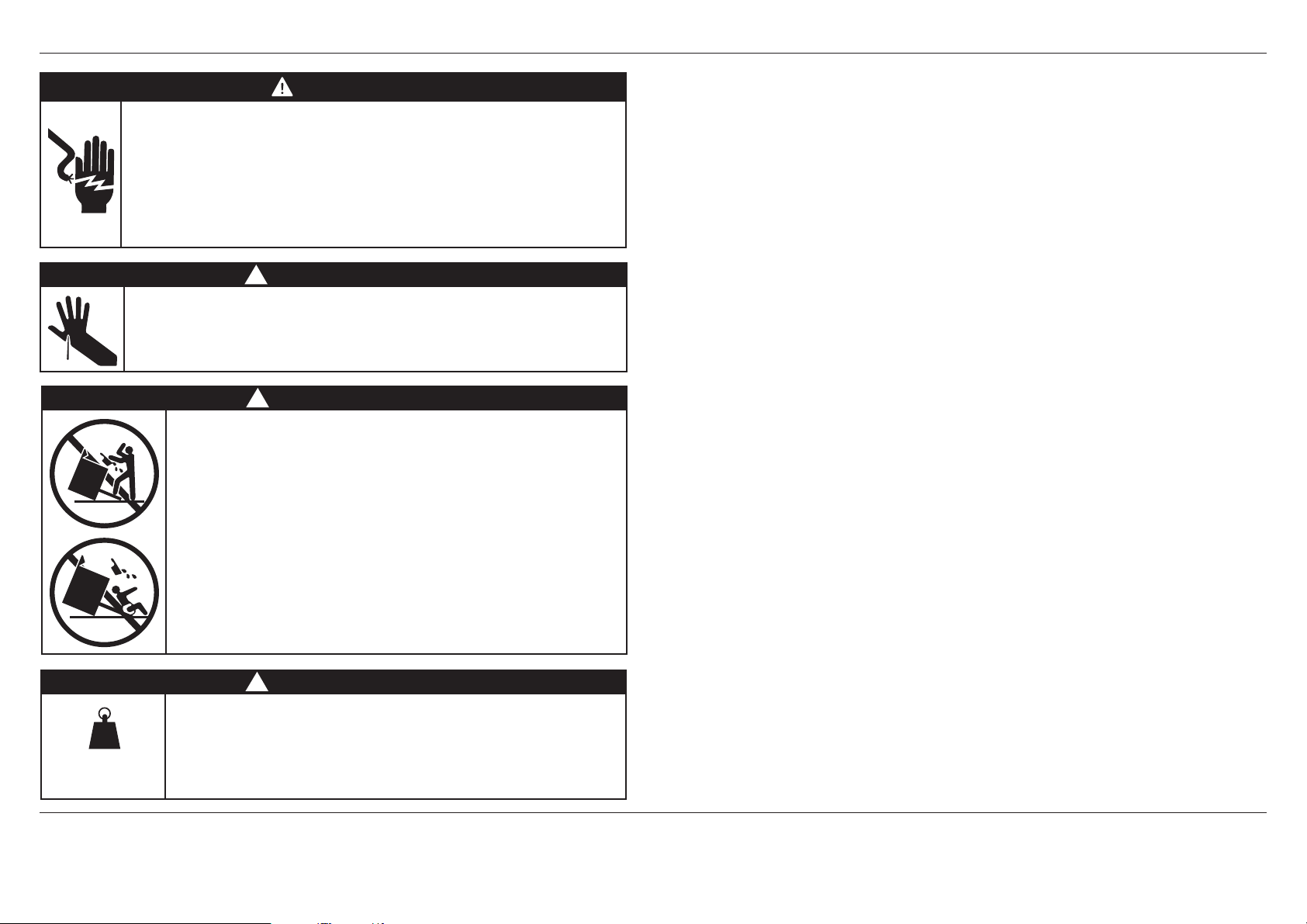
Electrical shock hazard
Before carrying out any work on the electrical section of the appliance,
it must be disconnected from the mains electricity supply.
Connection to a good ground wiring system is absolutely essential
and mandatory.
Alterations to the domestic wiring system must only be made by a
qualified electrician
Failure to follow this advice may result in electrical shock or death.
Cut Hazard
Take care – panel edges are sharp.
Failure to use caution could result in injury or cuts.
420-630 lb
190-285 kg
WARNING!
!
WARNING!
!
WARNING!
To reduce the risk of tipping the appliance, the appliance must
be secured by properly installed anti-tip device packed with the
appliance.
●
A child or adult can tip the range and be killed.
●
Install the anti-tip device to the structure by fastening the
supplied bracket to the floor and wall following the instructions
for installing the anti-tip device.
●
Engage the anti-tip device.
●
Re-engage the anti-tip device if the range is moved.
●
See installation instructions for details.
Failure to do so can result in death or serious burns to children
of adults.
!
WARNING!
Extremely Heavy
Proper equipment and adequate manpower must be used in moving
the range to avoid personal injury or damage to the unit or the
floor. The unit is heavy and rests on adjustable steel legs.
Failure to follow this advice may result in damage or personal injury.
IMPORTANT SAFETY INSTRUCTIONS!
●
Save these instructions for the local inspectors use.
●
To avoid hazard, follow these instructions carefully before installing or using this appliance.
●
Please make this information available to the person installing the appliance – doing so could
reduce your installation costs.
●
This range is to be installed and connected to the electricity supply only by an authorized
person.
●
If the installation requires alterations to the domestic electrical system, call a qualified
electrician. The electrician should also check that the socket cable section is suitable for the
electricity drawn by the range.
●
Service should only be done by authorized technicians. Technicians must disconnect the
power supply before servicing this appliance.
●
The range must be grounded.
●
Installation must comply with your local building and electricity regulations.
●
This appliance must be installed and connected to the mains power supply only by a suitably
qualified person according to these installation instructions and in compliance with any
applicable local building and electricity regulations. Failure to install the appliance correctly
could invalidate any warranty or liability claims.
●
Ensure the installer shows the customer where the gas supply shut-off valve is located.
●
If the power supply cable is damaged, it must be replaced by the manufacturer, its service
agent or similarly qualified person in order to avoid a hazard.
●
A circuit breaker is recommended.
●
Do not use adaptors, reducers or branching devices to connect the oven to the mains
electricity supply, as they can cause overheating and burning.
●
Improper installation, adjustment alteration, service or maintenance can cause property
damage, injury or death. Read the installation, operating and maintenance instructions
thoroughly before using, installing or servicing this appliance.
●
A risk of the appliance tipping over exists if the appliance is not installed in accordance with
installation instructions.
●
DO NOT obstruct the flow of combustion or ventilation air to the appliance. Be sure a fresh air
supply is available.
●
California Proposition 65 – The burning of gas cooking fuel generates some by-products which
are known by the State of California to cause cancer or reproductive harm. California law
requires businesses to warn customers of potential exposure to such substances. To minimize
exposure to these substances, always operate this unit according to the manufacturer’s
instructions and provide good ventilation to the room when cooking with gas.
●
Check local building codes for the proper method of range installation. Local codes vary.
Installation, electrical connections, and grounding must comply with all applicable codes.
In the absence of local codes, the range should be installed in accordance with the latest
edition of National Fuel Gas Code ANSI Z223.1 and National Electrical Code ANSI / NFPA 70.
●
In Canada: Installation must be in accordance with the current CAN/CGA B149.1 & 2 Gas
Installation codes and/or local codes. Electrical installation must be in accordance with the
current CSA C22.1 Canadian Electrical Codes Part 1 and/or local codes.
●
Be sure that the unit being installed is set up for the kind of gas being used. The gas range
is shipped from the factory set and adjusted for Natural Gas or LP (propane), depending on
the specific model ordered. Verify that the range is compatible with the gas at the installation
site before proceeding further. Return range to dealer if the unit is not set for site gas supply.
●
The appliance must not be installed behind a decorative door in order to avoid overheating.
IMPORTANT!
SAVE THESE INSTRUCTIONS
The models shown in this installation guide may not be available in all markets and are subject to change at any time. For current details about model and specification availability in your country, please go to our
website www.fisherpaykel.com or contact your local Fisher & Paykel dealer.
3
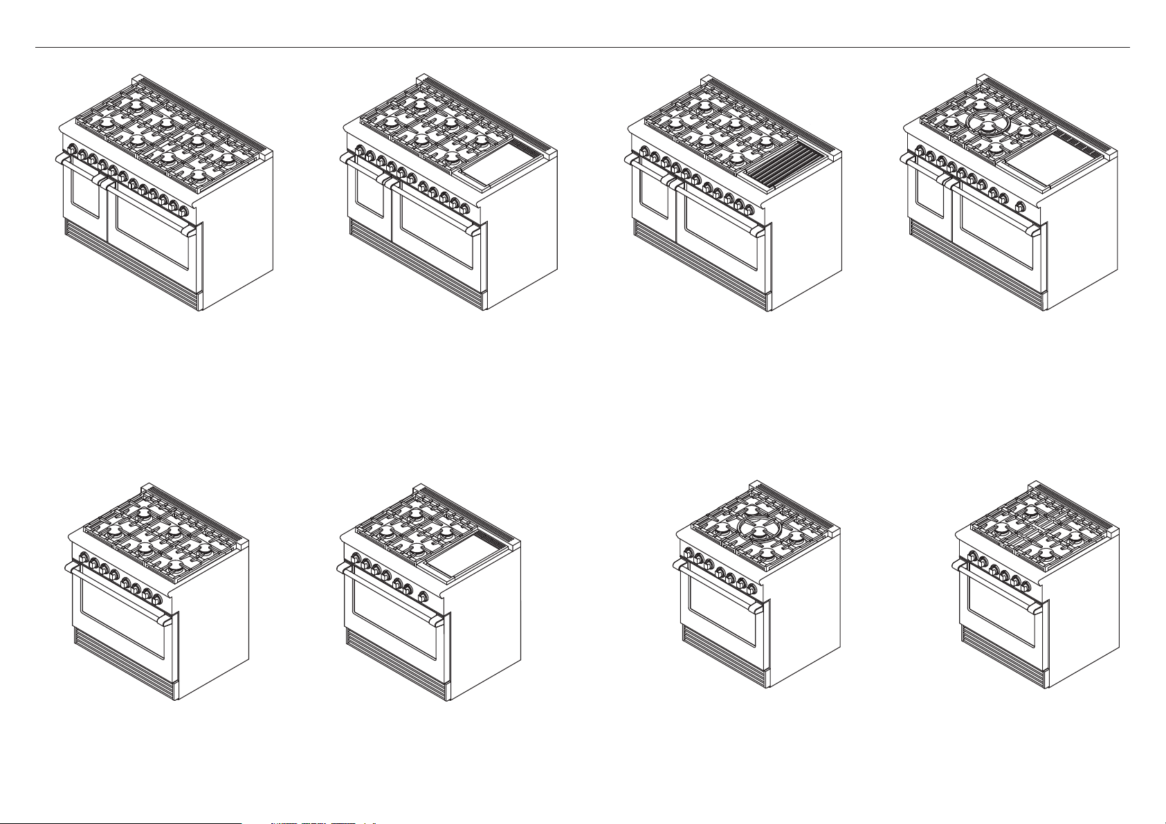
48” MODELS
2MODEL IDENTIFICATION
RGV2-488
RDV2-488
36” MODELS
RGV2-486GD
RDV2-486GD
RGV2-486GL
RDV2-486GL
30” MODELS
RGV2-485GD
RDV2-485GD
4
RGV2-366
RDV2-366
RGV2-364GD
RDV2-364GD
RGV2-305
RDV2-305
RGV2-304
RDV2-304
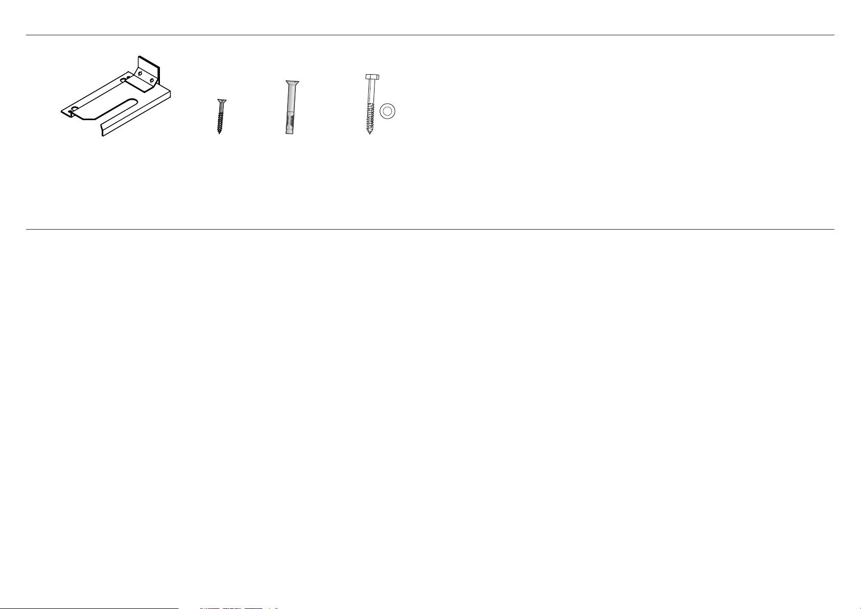
3PARTS SUPPLIED FOR INSTALLATION
Anti-tip bracket (1) 5/16” x 1 1/2”
#10 x 2”
wood screws (4)
sleeve anchors (2)
Lag bolts and
washers (2)
4UNPACKING AND HANDLING THE RANGE
Unpacking and handling
●
Inspect the product to verify that there is no shipping damage. If any damage is detected, call the shipper and initiate a damage claim. Fisher & Paykel is not responsible for shipping damage.
●
DO NOT discard any packing material (box, pallet, straps) until the unit has been inspected.
●
Remove the outer carton and any packing material from the shipping base.
IMPORTANT!
●
DO NOT lift range by the oven door handles!
●
DO NOT remove the grill or griddle assemblies!
5
B
C
C
F
H
I
D
J
E
G
A
FRONT
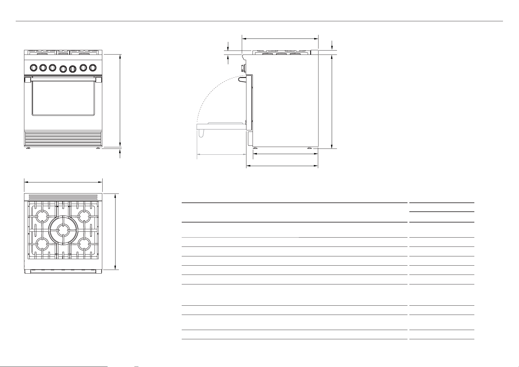
5PRODUCT DIMENSIONS – 30” MODELS
PROFILE
RGV2-305 shown for Illustration purposes only
PRODUCT DIMENSIONS
PLAN
6
Overall height of range (from floor to cooktop, excluding
A
pan supports and vent trim)
Overall width of range 29 7/8” (759)
B
Overall depth of range (excluding handle and dials) 29 1/8” (740)
C
Depth from rear of chassis to cabinetry face – projecting control panel 25 1/8” (638)
D
Depth from rear of chassis to cabinetry face – flush control panel 27 11/16” (703)
E
Height from top of countertop to top of pan supports 1 9/16” (40)
F
Height from top of countertop to top of
G
- vent trim (if fitted)
- angled vent trim (if fitted)
Height from top of countertop to bottom of chassis 35 1/4” (895)
H
Adjustable feet height min 1/2’’ (13)
I
Depth of open door to front control panel 19 1/8” (486)
J
30” MODELS
inches (mm)
min 35 3/4’’ (908)
max 36 3/4’’ (933)
1 3/4” (45)
3 1/2” (90)
max 1 1/2’’ (38)

B
C
H
I
C
F
D
J
E
G
A
FRONT
5PRODUCT DIMENSIONS – 36” MODELS
PROFILE
RGV2-364GD shown for Illustration purposes only
PLAN
PRODUCT DIMENSIONS
Overall height of range (from floor to cooktop, excluding
A
pan supports and vent trim)
Overall width of range 35 7/8” (911)
B
Overall depth of range (excluding handle and dials) 29 1/8” (740)
C
Depth from rear of chassis to cabinetry face – projecting control panel 25 1/8” (638)
D
Depth from rear of chassis to cabinetry face – flush control panel 27 11/16” (703)
E
Height from top of countertop to top of pan supports 1 9/16” (40)
F
Height from top of countertop to top of
G
- vent trim (if fitted)
- angled vent trim (if fitted)
Height from top of countertop to bottom of chassis 35 1/4” (895)
H
Adjustable feet height min 1/2’’ (13)
I
Depth of open door to front control panel 19 1/8” (486)
J
36” MODELS
inches (mm)
min 35 3/4’’ (908)
max 36 3/4’’ (933)
3 1/2” (90)
max 1 1/2’’ (38)
1 3/4” (45)
7
B
C
H
I
C
F
D
J
E
G
A
FRONT
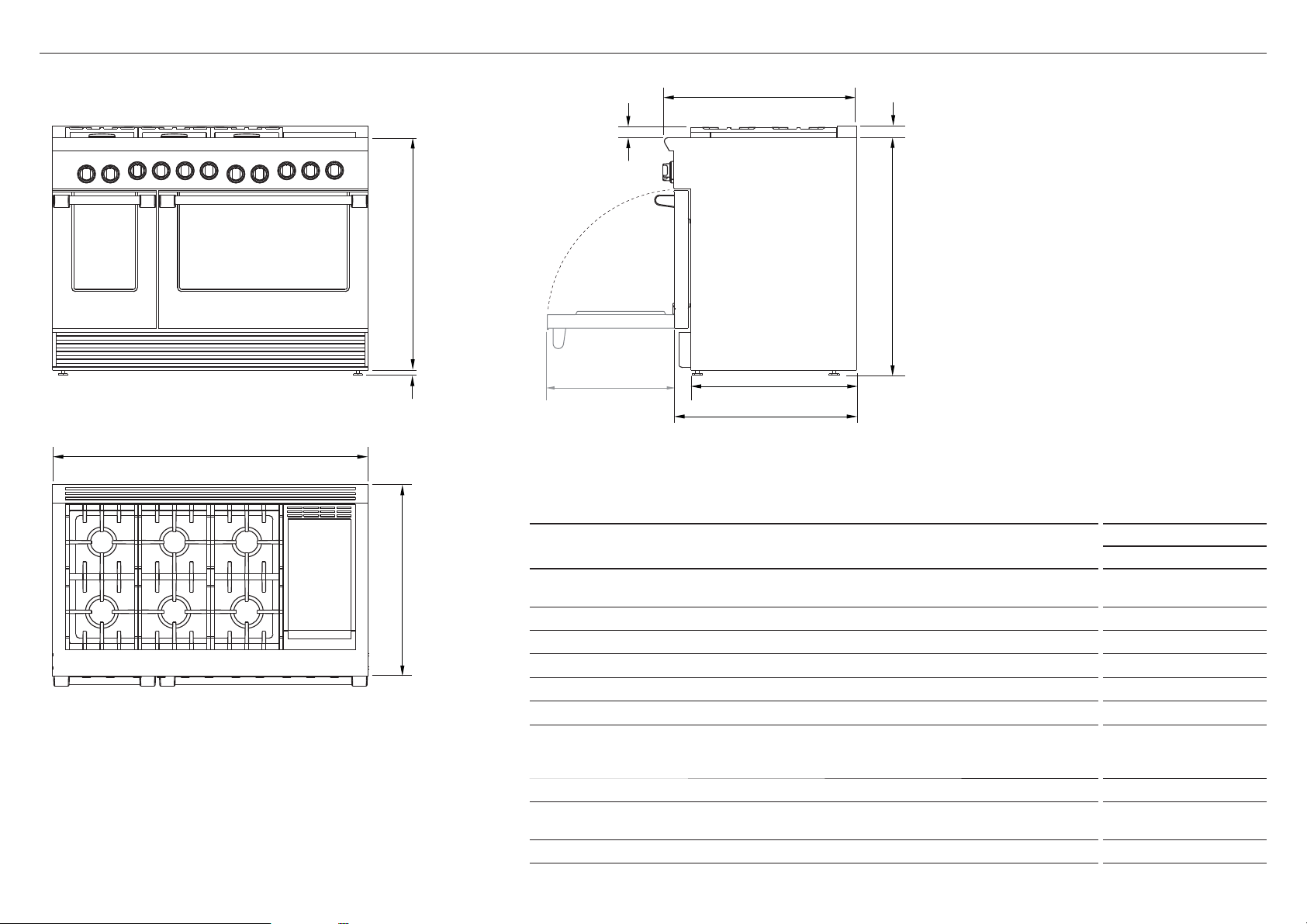
5PRODUCT DIMENSIONS – 48” MODELS
PROFILE
RGV2-486GD shown for Illustration purposes only
48” MODELS
inches (mm)
min 35 3/4’’ (908)
max 36 3/4’’ (933)
1 3/4” (45)
3 1/2” (90)
max 1 1/2’’ (38)
PLAN
PRODUCT DIMENSIONS
Overall height of range
A
(from floor to cooktop, excluding pan supports and vent trim)
Overall width of range 47 7/8” (1216)
B
Overall depth of range (excluding handle and dials) 29 1/8” (740)
C
Depth from rear of chassis to cabinetry face – projecting control panel 25 1/8” (638)
D
Depth from rear of chassis to cabinetry face – flush control panel 27 11/16” (703)
E
Height from top of countertop to top of pan supports 1 9/16” (40)
F
Height from top of countertop to top of
G
- vent trim (if fitted)
- angled vent trim (if fitted)
Height from top of countertop to bottom of chassis 35 1/4” (895)
H
Adjustable feet height min 1/2’’ (13)
I
Depth of open door to front control panel 19 1/8” (486)
J
8
 Loading...