

Page 1

Freestanding cooker
OR90SDBGFX models
Installation instructions
and User guide
GB IE
Page 2

Page 3

Contents
1
Safety and warnings
Installation instructions
First use
Using your oven
Cooking functions
Cooking guide
Using the rotisserie
Using the electronic timer
Automatic cooking
Using your gas cooktop
Care and cleaning
Troubleshooting
Warranty and service
2
12
26
29
32
34
36
38
39
40
44
59
60
Important!
SAVE THESE INSTRUCTIONS
The models shown in this User Guide may not be available in all markets and are
subject to change at any time. For current details about model and specification
availability in your country, please go to our website www.fisherpaykel.com or
contact your local Fisher & Paykel dealer.
Page 4
2
Safety and warnings
Installation
Electrical Shock Hazard
Always disconnect the cooker from the
mains electricity supply before
carrying out any maintenance
operations or repairs.
Failure to do so may result in death or
electrical shock.
Cut Hazard
Take care - panel edges are sharp.
WARNING!
WARNING!
Failure to use caution could result in
injury or cuts.
Important safety precautions
General
To avoid hazard, follow these instructions
carefully before installing or using this product.
Please make this information available to the
person installing the product as it could reduce
your installation costs.
Installation must comply with your local
building and electricity regulations.
Failure to install the cooker correctly could
invalidate any warranty or liability claims.
Page 5

Safety and warnings
Some appliances have a protective film. Remove
this film before using the cooker.
After unpacking the appliance, check to to
ensure it is not damaged and the door closes
correctly. If in doubt, do not use it and consult
your Authorised Dealer or a professionally
qualified technician.
Electrical
This cooker is to be installed and connected
to the electricity supply only by an authorised
person.
If the installation requires alterations to the
domestic electrical system call a qualified
3
electrician. He should also check that the
electrical system is suitable for the electricity
drawn by the cooker.
The appliance must be connected to the mains,
checking that the voltage corresponds to the
value given in the rating plate and that the
electrical cable sections can withstand the load
specified on the plate.
A suitable disconnection switch must be
incorporated in the permanent wiring, mounted
and positioned to comply with the local wiring
rules and regulations. The switch must be of an
approved type installed in the fixed wiring and
provide a 3 mm air gap contact separation in all
poles in accordance with the local wiring rules.
Page 6

4
Safety and warnings
Electrical
The switch must always be accessible.
The power supply cable must not touch any hot
parts and must be positioned so that it does not
exceed 75
O
C at any point and cannot become
entrapped in the oven door.
To connect the cooker to the mains, do not use
adapters, reducers or branching devices as they
can cause overheating and burning.
This cooker must be connected to a suitable
double pole control unit adjacent to the cooker.
No diversity can be applied to this control unit.
The cooker must be earthed.
Gas
This cooker is supplied for use with natural gas
only, and cannot be used on any other gas
without modification. See ‘Gas installation’ for
modification to other gas types.
This cooker can only be installed in a room
with adequate ventilation. See the ‘Ventilation
requirements’ in the installation instructions .
Page 7

Safety and warnings
General
Do not leave packing elements (plastic bags,
polystyrene foam, nails, packing straps etc)
around within easy access of children, as these
may cause serious injuries.
Read the instructions carefully before installing
and using the appliance.
The manufacturer declines all liability for injury
to persons or damage to property caused by the
incorrect use or improper use of the appliance.
If you should decide to dispose of this cooker,
we recommended that it be made inoperative in
an appropriate manner in accordance to health
and environmental protection regulations. In
5
particular, ensure that all potentially hazardous
parts are made harmless, especially in regard to
children who could play with unused appliances.
Various components of the appliance are
recyclable. Dispose of them in accordance with
the regulations in force in your country. If the
appliance is to be scrapped, remove the power
cord.
Page 8
6
Safety and warnings
Operation
Your freestanding cooker has been carefully designed to operate safely during normal cooking
procedures. Please keep the following guidelines in mind when you are using it:
WARNING!
Explosion Hazard
Do not store flammable materials such
as gasoline near the cooktop.
Do not store flammable material in the
ovens or in the storage compartment.
Do not spray aerosols near the cooktop
during use.
Failure to do so may result in death or
serious injury.
WARNING!
Electrical Shock Hazard
Switch the cooker off at the wall before
replacing fuses or the oven lamp.
Failure to do so may result in death or
electrical shock.
Page 9
Safety and warnings
WARNING!
7
Hot Surface Hazard
Accessible parts will become hot when
this cooker is in use.
To avoid burns and scalds keep children
away.
Do not touch hot surfaces inside the
ovens.
Use oven mitts or other protection
when handling hot surfaces such as
oven shelves or dishes.
Take care when opening the oven door.
Let hot air or steam escape before
removing or replacing food.
Do not touch the cooktop components,
burners, trivets/pan supports or the
base when hot.
Before cleaning, turn the cooker off and
make sure it is cool.
Failure to do so could result in burns
and scalds.
Page 10

8
Safety and warnings
Important safety precautions
Never leave the appliance unattended
when in use. Boilover causes smoking and
greasy spillovers that may ignite. NEVER try
to extinguish a fire with water. Switch the
appliance off at the wall and then cover the
flame with a lid or fire blanket.
Isolating switch: make sure this cooker is
connected to a circuit which incorporates an
isolating switch providing full disconnection
from the power supply.
Household appliances are not intended to
be played with by children. Children of less
than 8 years old must be kept away from the
appliance unless continuously supervised. This
appliance can be used by children aged from
8 years and above, and persons with reduced
physical, sensory or mental capabilities or lack
of experience and knowledge, if they have been
given supervision or instruction concerning
the use of the appliance in a safe way and they
understand the hazards involved.
Cleaning and user maintenance shall not be
done by children without supervision.
Safe food handling: leave food in the oven for
as short a time as possible before and after
cooking. This is to avoid contamination by
organisms which may cause food poisoning.
Page 11

Safety and warnings
Take particular care during warmer weather.
Do not place aluminium foil, dishes, trays, water
or ice on the oven floor during cooking as this
will irreversibly damage the enamel.
Do not line the oven walls with aluminium foil.
Do not stand on the door, or place heavy objects
on it.
Do not use harsh abrasive cleaners or sharp
metal scrapers to clean the oven door glass since
they scratch the surface, which may result in
shattering of the glass.
Do not use a steam cleaner to clean any part of
the cooker.
Do not use an asbestos mat or decorative covers
9
between the flame and the saucepan as this
may cause serious damage to your cooktop. Do
not place aluminium foil or plastic dishes on the
cooktop burners.
Do not let large saucepans or frying pans
overlap the bench as this can deflect heat onto
your benchtop and damage the surface.
Do not let large saucepans, frying pans or
woks push any other pans aside. This could
make them unstable or deflect heat onto your
benchtop and damage the surface.
Saucepan handles may be hot to touch. Ensure
saucepan handles do not overhang other gas
burners that are on. Keep handles out of reach
of children.
Page 12

10
Safety and warnings
Do not hang towels, dishcloths or other items
on the cooker or oven door handle as this is a
potential a fire hazard.
If the electrical supply cord is damaged, it must
only be replaced by an authorised person.
Do not touch the cooker with wet hands or feet.
Do not operate whilst in bare feet.
This cooker is not to be used as a space heater.
The use of a gas cooking appliance results in
the production of heat and moisture in the
room in which it is installed. Ensure the kitchen
is well ventilated. Keep natural ventilation
holes open or install a mechanical ventilation
device (mechanical extractor hood). Prolonged
intensive use of the appliance may call for
additional ventilation, for example opening
of a window, or more effective ventilation, for
example increasing the level of mechanical
ventilation where present.
Do not operate the cooker by means of an
external timer or separate remote-control
system.
Do not modify this appliance as it may become
dangerous to use. The manufacturer declines all
responsibility for any inconvenience or damage
to persons or property arising from the nonobservance of this condition.
Page 13

Safety and warnings
The manufacturer declines all liability for
damage to property cause by the incorrect or
improper use of the appliance.
Important! This appliance is designed and
manufactured solely for the cooking of domestic
(household) food and it not suitable for any non
domestic application and therefore should not
be used in a commercial environment.
The appliance guarantee will be void if the
appliance is used with in a non domestic
environment ie a semi-commercial, commercial
or communal environment.
11
Page 14
12
Installation instructionsInstallation instructions
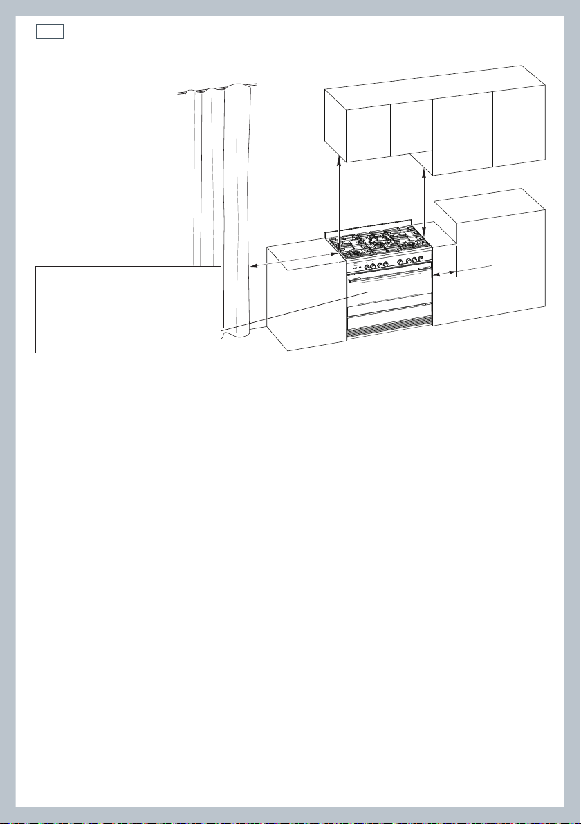
650 mm
500 mm
450 mm
200 mm
Cooker overall dimensions [mm]
•
height:
•
product width: 897
•
depth: 600
•
cavity width 900
min 897 - max 910
Fig. 1 Dimensions and
distances from cooker
The cooker must be installed by a qualified technician and in compliance with local
safety standards. This cookers has class “2/1” overheating protection so that it can be installed
next to a cabinet.
If the cooker is installed adjacent to furniture which is higher than the gas hob cooktop, a
gap of at least 200 mm must be left between the side of the cooker and the furniture.
The furniture walls adjacent to the cooker must be made of material resistant to heat.The
veneered synthetical material and the glue used must be resistant to a temperature of 90°C in
order to avoid ungluing or deformations.
The cooker may be located in a kitchen, a kitchen/diner or bed-sitting room but not in a room
containing a bath or shower.
Curtains must not be fitted immediately behind appliance or within 500 mm of the sides.
If the cooker is located on a pedestal it is necessary to provide safety measures to prevent falling
out.
It is essential that the cooker is positioned as stated.
Page 15
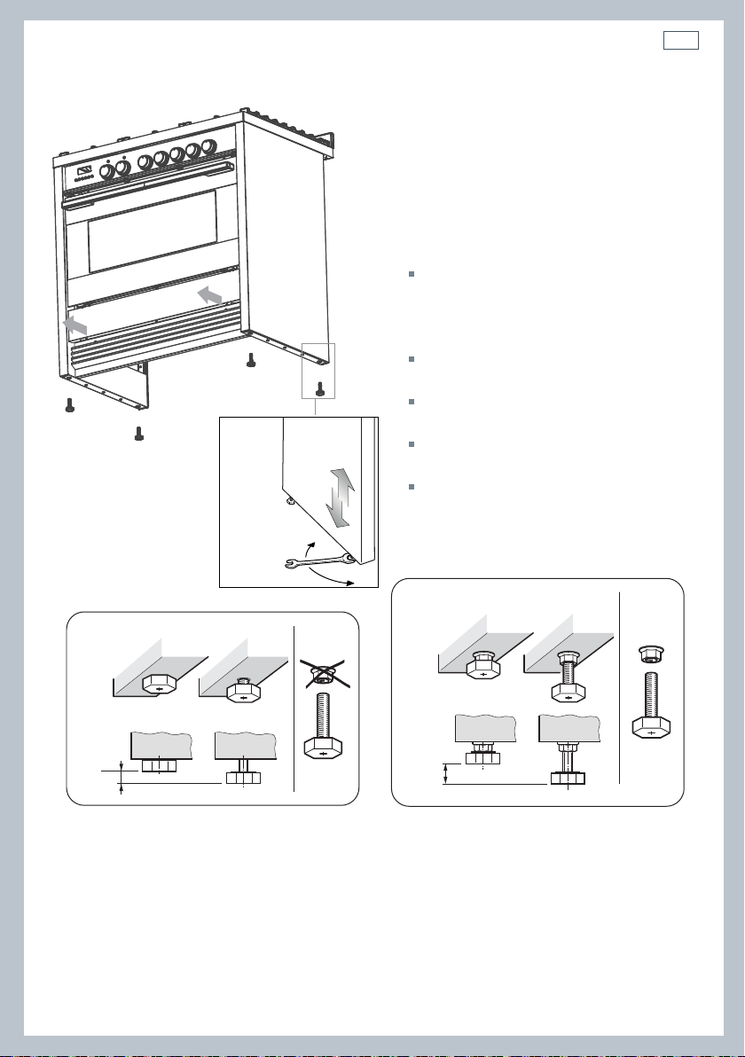
Fig. 2a Screw/unscrew the
feet to get the required height
Installation instructions
Levelling the cooker
Important!
Using the supplied adjustable feet is
MANDATORY. For safety reasons and to
ensure adequate ventilation, the cooker
chassis MUST NOT sit directly on the floor, a
plinth, or other support surface.
For ease of installation, first remove
the kickstrip. To remove the kickstrip,
unscrew the two screws holding it in
place.
The cooker is already fitted with four
levelling feet.
Level the cooker by screwing or
unscrewing the feet.
Make sure you follow the instructions in
Figs. 2a, 2b, and 2c.
Note: nuts are supplied with the cooker
in a separate kit.
Do not refit the kickstrip until you have
installed the anti-tip bracket.
13
0
+ 8
mm
Fig. 2b Do not use the supplied nuts for height
adjustments between 0 and 8 mm
+ 8
mm
+ 13
mm
height adjustments between 8 and 13 mm
Fig. 2c Use the supplied nuts for
Page 16
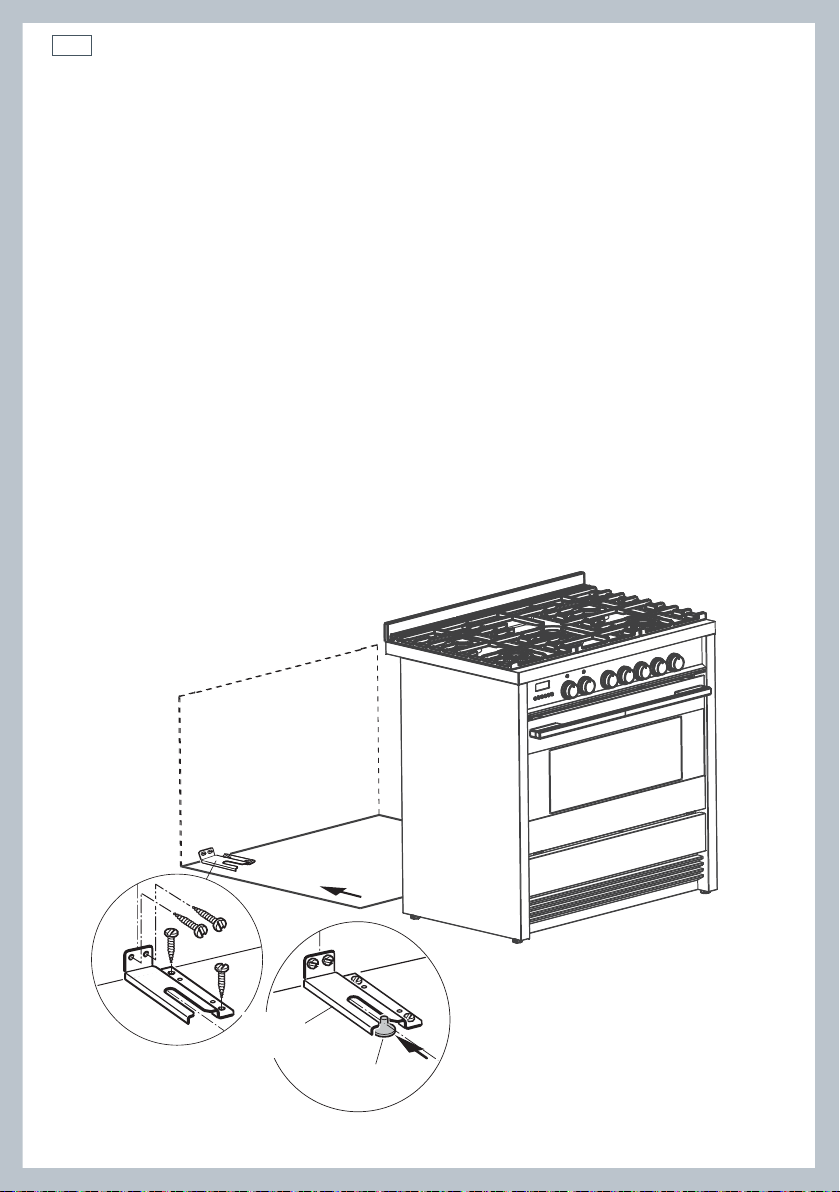
14
Dotted line showing the position
of the cooker when installed
Rear left
foot of cooker
Anti-tilt
bracket
Installation instructionsInstallation instructions
Fitting the anti-tilt bracket
Important!
To restrain the appliance and prevent it tipping accidentally, the anti-tilt bracket supplied must be fitted
according to the instructions below.
1
Drill four 8mm diameter holes for the fixing screws (two in the wall and two in the floor-see
Fig.3) and insert the plastic plugs supplied.
Important!
Before drilling the holes, check that you will not damage any pipes or electrical wires.
2
Attach the anti-tilt bracket to the floor and rear wall using the four screws supplied, as shown in
Fig. 3.
3
After attaching the anti-tilt bracket securely, slide the cooker into place. Ensure that the left rear
foot slides under the bracket, as shown in Fig.3.
4
Replace the kickstrip using the two screws.
Important!
When sliding the cooker into place be careful not to trap the power supply cable in the anti-tip bracket. Pay
extra attention to the gas connection hose.
Beware of sharp edges when removing or replacing the drawer.
Fig. 3 Attaching the
anti-tilt bracket and
sliding the cooker
into place
Page 17
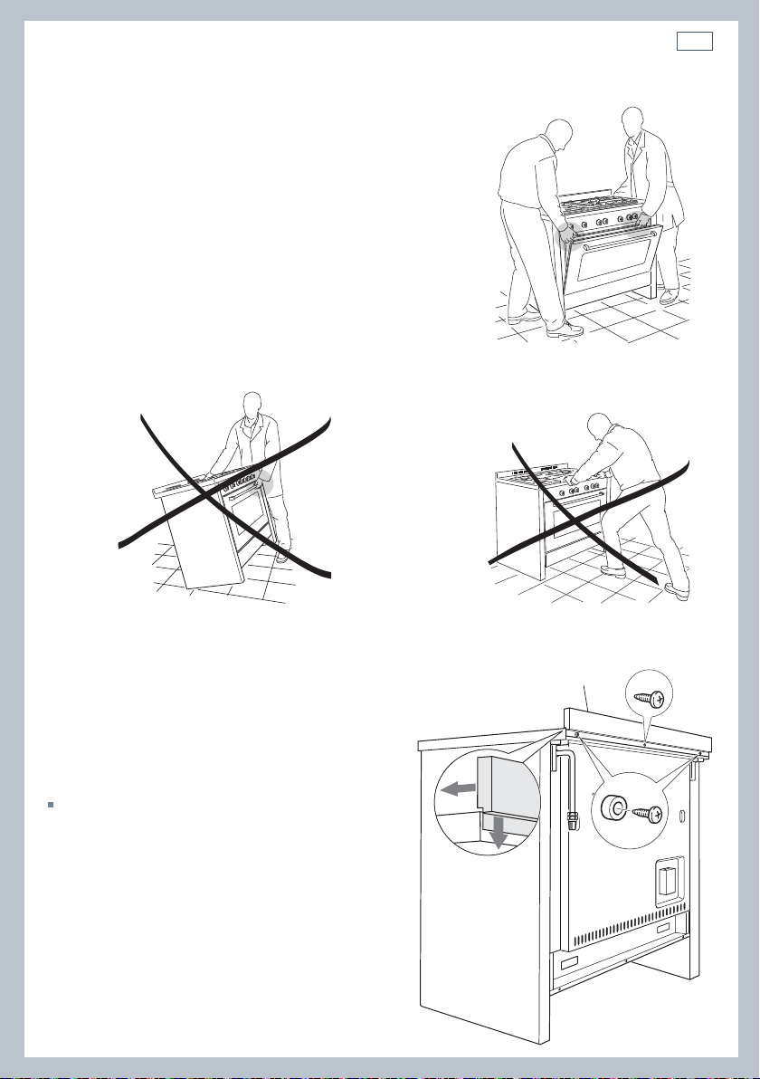
Moving the cooker
Important!
To prevent damaging the adjustable feet or lower
trim, ensure the cooker is always lifted by two
people.
Do not lift the cooker by the door handles.
DO NOT DRAG the cooker. Lift the feet clear of the
floor.
Installation instructions
Fig. 4 Correctly lifting the cooker
15
Fig. 5 Incorrectly lifting the cooker
Fixing the backguard
Before installing the cooker, assemble the
backguard “C” .
The backguard “C” can be found packed
at the rear of the cooker.
1
Before assembling, remove any protective
film/adhesive tape.
2
Remove the two spacers “A” and the
screw “B” from the rear of the cooktop.
3
Assemble the backguard as shown and
fix it by screwing the central screw “B”
and the spacers “A”.
Fig. 6 Incorrectly moving the cooker
C
B
A
Fig. 7 Assembling
the backguard
Page 18
16
Installation instructionsInstallation instructions
Ventilation requirements
The appliance should be installed into a room or space with an air supply in accordance with BS
5440-2:2008.
For rooms with a volume of less than 5 m
required.
For rooms with a volume of between 5 m
will be required unless the room has a door which opens directly to the outside air in which case
no permanent ventilation is required.
For rooms with a volume greater than 10 m
3
- permanent ventilation of 100 mm2 free area will be
3
and 10 m3 a permanent ventilation of 50 cm2 free area
3
- no permanent ventilation is required.
Important!
Regardless of room size, all rooms containing the appliance must have direct access to the outside air via
an openable window or equivalent.
Where there are other fuel burning appliances in the same room, BS 5440-2:2008 should be
consulted to determine the correct amount of free area ventilation requirements.
Gas installation
Important!
This cooker uses NATURAL GAS only and cannot be used on any other gas without modification. This
appliance is manufactured for conversion to LPG if required. If the injectors are not supplied they can be
obtained from the After-Sales Service.
Installation and service regulations
Important!
This appliance must be installed and serviced only by a suitably qualified and registered person, and in
accordance with the current editions of the following standards and regulations or other locally applicable
regulations:
Gas Safety (Installation and Use) Regulations
Building Regulations
British Standards
Regulations for Electrical Installation
Failure to install the appliance correctly could invalidate any manufacturer’s warranty
and lead to prosecution under the above-quoted regulation.
Gas connection
The installation of the cooker to Natural Gas or LP Gas must be carried out by a qualified
gas engineer. Installers shall take due account of the provisions of the relevant British
Standards Code of Practice, the Gas Safety Regulations and the Building Standards (Scotland)
(Consolidation) Regulations issued by the Scottish Development Department.
Note: It is recommended that the gas connection to the cooker is installed with a flexible
connecting tube made to BS 5386.
Page 19
Installation instructions
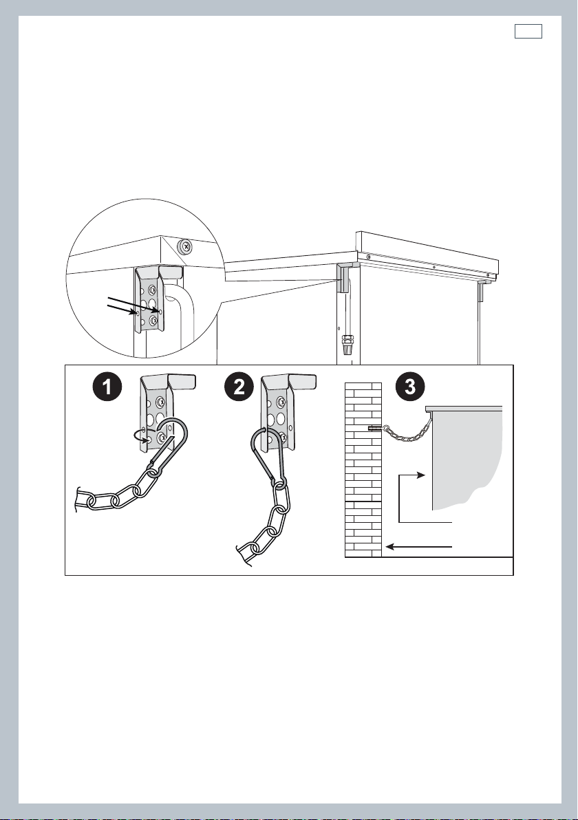
Attaching a restraining chain
It is a requirement that a restraining chain (not supplied with the appliance) is used to prevent
stress being applied to the gas hose or pipework. The chain should be attached securely to the
product and on the wall (Fig. 8a).
Chain
security
holes
17
Cooker
Back of
the cooker
Rear wall
Fig. 8a Attaching restraining chain.
Page 20
18
Installation instructionsInstallation instructions
Installation to Natural gas
The installation must conform to the relevant British Standards. Installation to Natural Gas must
conform to the Code of Practice, etc. The supply pressure for Natural Gas is 20 mbar.
Installation to Liquid Petroleum gas
This appliance must only be connected to LPG after an LPG conversion kit has been fitted. The
installation must conform to the relevant British Standards.
Important!
Only a suitably qualified and registered person may convert the appliance to a different gas type.
When using Butane gas a supply pressure of 28 -30 mbar is required.
When using Propane gas a supply pressure of 37 mbar is required.
Notes:
Flexible hoses can be used where the sited ambient temperature of the hose does not exceed
70°C. These hoses must be manufactured in accordance with BS669 part 1 and be of the correct
construction for the type of gas being used.
Gas hoses designed for natural gas MUST NOT be used for supplying LPG gas (LPG gas hoses can
be identified by a either a red band or stripe on the rubber outer coating of the hose).
The hose should not be crushed or trapped or be in contact with sharp or abrasive edges.
It should also not be subjected to corrosion by acidic cleansing agents. The hose should be
connected in such away that it does not touch the floor and must hang in a natural loop
between the appliance and the bayonet fitting.
Page 21

Installation instructions
To connect the gas supply:
1
Fit the 1/2” BSP (female) connector (supplied with the cooker in a separate kit) to the gas
inlet at the rear of the cooker interposing the gasket. Check the correct positioning of the
connector as shown and always use two suitable spanners (Fig 8c).
2
Connect the gas supply to the gas inlet at the rear of the cooker. The pipe is not to cross
the cooker.
3
To avoid damage to the appliance gas rail inlet pipe tighten
the fittings using two suitable spanners (Fig. 8c).
4
Using a suitable leak detection fluid solution (e.g. Rocol)
check each gas connection one at a time by brushing the
solution over the connection. The presence of bubbles will
indicate a leak. If there is a leak, tighten the fitting and
then recheck for leaks.
IMPORTANT!
Do not use a naked flame to test for leaks.
It is the responsibility of the gas installer to ensure that the
product is fully tested and commissioned in accordance with
current regulations and to ensure there are no gas leaks.
Gas
inlet pipe
19
Fig. 8b Gas
supply inlet
Cooker manifold
Manifold male
pipe fitting
1/2” G cylindrical
(ISO 228-1) male
Gasket (*)
1/2” G cylindrical
(ISO 228-1) female
Connector (*)
1/2” BSP (female)
(*) Supplied with the appliance in a separate kit.
20 mm
20 mm
10 mm
10 mm
Fig. 8c Connecting the gas
Page 22

20
Installation instructions
Rear wall
700 mm
Suggested area for
gas mains connection
200 mm
Fig. 8d Gas mains connection area.
Converting to a different gas type
This appliance is suitable for use with Natural gas or LPG (check the “gas type” sticker attached to
the appliance). To convert from one gas type to another, you need to replace the injectors, and
then adjust the minimum burning setting.
Replacing the injectors
1 Remove the trivets and burners from the cooktop.
2 Using a spanner, remove the injectors (shown in Figs. 9‐10‐11 following) and replace them with
ones according to the gas type (see the ‘Table for the choice of injectors’).
3 Fix the warning label (supplied with the conversion kit) at the back of the cooker, near the gas
inlet connection. This label states that the gas cooktop has been converted for use with LPG/
Natural gas.
Adjusting the minimum burner setting
4 See ‘Adjusting the minimum burner setting’.
Note: The burners are designed so that regulation of the primary air is not required.
Page 23

Installation instructions
21
Injector
Fig. 9 Semi-rapid burner Fig. 10 Triple-ring wok burner
Injector
J
Injector for
Injector for
inner crown
ner crown
J
Injectors for
Injectors for
outer crown
outer crown
J
Fig. 11 Dual burner
Page 24

22
Installation instructions
Adjusting the minimum burner setting
Check whether the flame spreads to all burner ports when the burner is lit with the gas valve set
to the minimum position.
If some ports do not light, increase the minimum gas rate setting. Check whether the burner
remains lit even when the gas valve is turned quickly from the maximum to the minimum
position.
If the burner does not remain lit, increase the minimum gas rate setting.
To adjust the minimum gas rate setting:
Semi-rapid and triple-ring burners:
1
Turn on the burner.
2
Turn the valve to the MINIMUM position.
3
Take off the dial.
4
Using a small flat screwdriver, turn the screw (see Fig. 12) to the correct regulation.
Inside crown of dual burner:
1
Turn on the burner.
2
Turn the valve to the MINIMUM position of the inner crown only.
3
Take off the dial.
4
Using a small flat screwdriver, turn the screw (see Fig. 13) to the correct regulation.
Outside crown of dual burner:
1
Turn on the burner.
2
Turn the valve to the MINIMUM position of the inner and outer crowns.
3
Take off the dial.
4
Using a small flat screwdriver, turn the screw (see Fig. 13) to the correct regulation.
Note: for LPG, the regulation screw is normally tightened up.
regulation screw
regulation screw
regulation screw
(outside crown)
Fig. 12 Adjusting the minimum burner setting:
semi-rapid and triple-ring wok burner
Fig. 13 Adjusting the minimum burner setting:
regulation screw
(inside crown)
dual burner
Page 25

IE
Table for the choice of the injectors
Installation instructions
23
GB
BURNERS
Semi-rapid
Triple-ring wok
Inner crown
Dual
Outer crown
(*) Power calculated with inner crown operating
(#) Power calculated with inner and outer crowns operating
Cat: II 2H3+
LPG
Nominal
power [kW]
1,75 0,45 66 101
3,50 1,50 93 135
0,80 (*) 0,35 (*)
4,50 (#) 1,90 (#)
Reduced
power [kW]
G30 - 28-30 mbar
G31 - 37 mbar
Injector Dia.
[1/100 mm]
46
(no. 1 central)
70
(no. 2 outer)
Natural gas
G20 - 20 mbar
Injector Dia.
[1/100 mm]
70
(no. 1 central)
104
(no. 2 outer)
Lubrication of the gas taps
A qualified technician must lubricate the gas taps.
Important!
All intervention regarding installation maintenance and conversion of the appliance must be fulfiled with
original factory parts.
The manufacturer declines any liability if these correct parts are not used.
Page 26

24
Installation instructions
Connecting the power supply cable
Important!
This cooker must be connected to the electricity supply only by an authorised person.
Feeder cable section
This cooker must be connected to electrical supply using H05RR-F insulated cable
220-240V~ 3 x 1,5 mm
To connect the power supply cable to the cooker, it is necessary to:
1 Unhook the terminal board cover by inserting a screwdriver into the two hooks ‘A’ (fig. 14).
2 Unscrew the screw ‘D’ and open completely the cable clamp ‘E’ (figs. 15).
3 Connect the phase, neutral and earth wires to terminal board ‘G’ according to the diagrams in
Fig. 15.
4 Strain the feeder cable and block it with cable clamp ‘E’ (by screwing screw ‘D’).
5 Close the terminal block cover (check the two hooks ‘A’ are correctly hooked).
2
cable.
Important!
To connect the power supply cable DO NOT unscrew the screws fixing the cover plate behind the terminal
block. WARNING: If the power supply cable is damaged, it must be replaced only by an authorised service
agent in order to avoid a hazard.
Voltage and power consumption
220-240V ~ 50/60Hz 3680W 16A (230V)*
* Connection with wall box connection
1
L1
3
N
L2
5
D
PE
G
2
4
E
220-240 V
1
1
L
2
3
A
N (L2)
4
5
Fig. 14 Terminal block Fig. 15 Connection diagrams
PE
Page 27

25
Page 28

26
First use
21011
1 34 5 67 89
Fig. 16 Control panel
8
1
Control buttons
2
Clock display
3
Temperature dial
4
Function dial
5
Front left (triple-ring wok) burner dial
6
Rear left (semi-rapid) burner dial
7
Central (dual) burner dial
Rear right (semi-rapid) burner dial
9
Front right (triple-ring) burner dial
10
Function indicator light
11
Temperature indicator light
Page 29

First use
Buttons
sets the timer
sets the cooking time
sets the stop time for automatic cooking
set the oven temperature /
select Celsius or Fahrenheit
decreases the time and temperature
increases the time and temperature
Fig. 17 Clock display and control buttons
Illuminated symbols
If the display shows It means that... For more information
12:00
27
A
flashing
steadily lit
A
flashing and
beeping
steadily lit The timer is set See section ‘Using the electronic timer’
steadily lit The oven is heating up See section ‘Using your oven’
12:00
The clock needs to be set. See instructions below.
The oven is set for automatic
cooking.
Automatic cooking has finished
See section ‘Automatic cooking’
To set the clock
When the power to the appliance is turned on or restored after a power failure 12:00 will flash in
the display.
1 Press
2 Press
3 Press
time is set.
and together - the display will stop flashing. The clock is now set for 12:00.
and together again to change the time. The display will flash
and to set the time. After a few minutes the display will be steadily lit, showing the
To change the time
1 Press and together. The display will flash.
2 Press
After a few seconds the display will remain steadily lit, showing the time is set.
and to set the time.
Page 30

28
First use
Remove the side racks to fit the Catalytic panels (if not already fitted)
1
Remove all shelves and trays.
2
For easier access to the fixing screws, you may remove the oven door first. See ‘Removing and
refitting the oven door’ in Care and Cleaning.
3
Remove the side racks on both sides:
4
Using a small coin or a flat-head screwdriver, loosen and remove both fixing screws.
5
Gently remove the side rack.
Fig. 18 Refitting the side racks
Fitting the Catalytic panels
6
Fit the catalytic panel. When fitting the catalytic panel make sure that
- the arrows are pointing upwards
-the panel with the hole in it is on the right oven wall.
Refitting the side racks
7
To refit the side racks
- make sure that they are the right way up, as in the illustrations, and that you
tighten the fixing screws.
8
If not already fitted, fit the telescopic sliding shelf supports. See “Care and cleaning’ for
instructions.
Page 31

Using your oven
Before using your new oven, please:
1
Read this user guide, taking special note of the ‘Safety and warnings’ section.
2
Remove all accessories and packaging. Peel the protective film off all surfaces and accessories.
3
Set the clock. The oven will not work until the clock has been set. See ‘Setting the clock’.
4
Fit the Catalytic panels and side racks. See opposite.
5
If not already fitted, fit the sliding shelf supports. See ‘Care and cleaning’ for instructions.
6
Slide in the shelves you will need, making sure that:
7
Heat the oven on maximum for:
8
Once cooled, wipe out the oven with a damp cloth and mild detergent, and dry thoroughly.
they are between the two wires of a shelf position;
the stop notches point down;
the guard rail is at the back.
Note: the grill tray should be positioned between the two wires of a shelf position and
orientated as shown.
60 minutes in the position
30 minutes in the position
15 minutes in the position
There will be a distinctive smell while you are conditioning your oven. This is normal, but
make sure your kitchen is well ventilated during the conditioning.
29
Guard rail
Stop notch
Stop
notch
Fig. 19 Correct position of shelves
and grill tray
Page 32

30
Using your oven
Temperature
indicator light
Fig. 20 Function and temperature dials
FUNCTION TEMPERATURE
Function
indicator light
210 C 225C
1
Select a function
Rotate the function dial to select a function
The function indicator light will come on.
The preset function temperature will flash
in the display. (Each cooking function has a
preset temperature)
If you wish to use the oven at the preset
temperature After a few seconds, the display will stop
flashing and the oven will turn on and
heat up. The display will revert to show the
actual oven temperature.
The indicator will show in the display.
Note: if you select , the display will
show dEF. The temperature cannot be
adjusted when using this function.
2a
There are two ways to set the
OR
Note: if the temperature display stops
2b
2c
Adjust the temperature
temperature while the display is
flashing:
Rotate the temperature dial (clockwise
to increase and anticlockwise to
decrease the temperature);
Use the and buttons to increase
or decrease the set temperature.
After a few seconds, the display will stop
flashing and the oven will turn on and
heat up. The display will revert to show
the actual oven temperature.
The indicator will show in the
display.
flashing before you have set the
required temperature, you can:
Press the button
The display will flash
Use the and buttons to increase
or decrease the set temperature.
Page 33

C89
3
When the oven is preheating and during
cooking
The indicator will show in the display.
The indicator will go out when the oven
has reached the set temperature.
Note: this indicator may turn on and off
during cooking as the oven maintains the
set temperature.
The temperature indicator light will
also come on when the oven is
heating and will turn on and off as
the oven maintains its set temperature.
The temperature indicator light goes
out when the oven has reached the set
temperature.
Using your oven
4a
To check the set temperature
Press the button.
The display will flash showing the set
temperature
After a few seconds the display will return
to the actual oven temperature and the
display will be steadily lit.
4b
To check the time of day
Press the button.
After a few seconds the display will show
the oven temperature again.
5
When you have finished cooking
Turn the function dial to o (off) to turn the
oven off.
31
Page 34

32
Cooking functions
OVEN LAMP
Only the oven light comes on. It remains on in all the cooking functions.
BAKE
The upper and lower heating elements come on. BAKE is the traditional method of cooking. It
is best to cook on only one shelf at a time in this function. Ideal for large cakes and dishes that
bake for several hours.
ROTISSERIE
A delicious way to cook meat and poultry. The slowly rotating meat is basted continuously
in its own juices, making it tender on the inside and well browned and full of flavour on the
outside. See ‘Using the rotisserie’.
GRILL
Grill is the most suitable function for ‘finishing off’ many meals, for example browning the top
of potato gratin and frittata. Use Grill to toast bread or to grill your favourite chicken, fish and
steak. Use with the oven door closed and the temperature set to a maximum of 225°C. For best
results, use the topmost shelf position when you want quick browning (eg toast).
DEFROST
this is not a cooking function
Only the oven fan comes on. The fan circulates air around the oven, speeding up the defrosting
process by approximately 30%. Note: this function is not for cooking food.
FAN FORCED
The circular heating element and the fan come on. The oven set on FAN FORCED can cook
several different foods together. Use FAN FORCED for multi-shelf cooking.
FAN GRILL
Both the grill and the fan come on. Use with the oven door closed and the temperature set to a
maximum of 225°C. Ideal for roasting tender cuts of meat and poultry. Use lower shelf positions
for larger items (eg a whole chicken).
Page 35

Cooking functions
WARM
this is not a cooking function
Always reheat food until piping hot and then select the warm function to keep food hot.
FAN BAKE
The upper and lower heating elements and the fan come on. Ideal for dishes like lasagne that
need to brown on top and also single trays of small cakes or biscuits that bake in less than an
hour.
Important!
Safe food handling: leave food in the oven for as short a time as possible before and after cooking or
defrosting. This is to avoid contamination by organisms which may cause food poisoning. Take particular
care during warmer weather.
33
Page 36

34
Cooking guide
Using the fat filter
Use the fat filter when roasting meat and poultry on
Fan Bake, Fan Grill or Fan Forced. It helps to keep
your oven clean and reduces splatter and smoking.
Remove the fat filter before baking.
Clean the fat filter after every use. See ‘Care and cleaning’.
Fig. 21 Fat filter
Changing the oven from Celsius to Fahrenheit
You can set your oven to display the temperature in Fahrenheit or Celsius.
1
Select a cooking function.
2
While the display is flashing, press to reduce the oven to the minimum temperature
o
(50
3
4
C / 120 oF)
When the display stops flashing , press and hold the button until C or F flashes in the display
Press the button to change between Celsius (C ) and Fahrenheit (F).
After a few moments the oven will turn off and the display will show the time of day.
Turn the function dial back to o (Off).
Cooking Guide
The settings in the following chart are guidelines only. Follow the instructions in your recipe or
on packaging and be prepared to adjust the oven settings and baking times to achieve the best
possible results for you.
Shelf positions are counted from the oven floor up (1 is the lowest, 5 is the highest).
Arrange oven shelves before you turn the oven on, then preheat the oven to the desired
temperature.
Single shelf positions below use the flat oven shelf; where a multi-shelf arrangement is
recommended, the lower position uses the step-down shelf.
Due to the width of the oven, a single shelf can usually accommodate double the standard
recipe.
Always preheat the oven before baking.
For models with a fat filter:
Always use the fat filter when roasting meat or poultry.
Always remove the fat filter before baking.
Do not place anything, including water or ice, on the oven floor
Keep the door completely shut when grilling foods.
Do not open the door during the first 3/4 of baking time.
Page 37

SAVOURY
Food Shelves
Roast Chicken
Lasagne
Quiche
Pizza
Casserole
Roast Lamb
(bone in)
Baked
Potatoes
Beef Steak
Beef Burgers
BAKING
Cooking guide
Recommended
Function
Rotisserie Rotisserie 1 180-210
Single Fan Bake 3 175-180 45-50
Single Pastry Bake 1 180-200 30-40
Single Pastry Bake 3 225-250 10-15
Single Fan Forced 3 170-190 55-70
Single
Single Bake 4 175-190 40-50
Single Grill 4 Hi 6-8 min / side
Single Grill 4 Hi
Fan Grill
(medium)
Shelf
positions
3 160-170
Temp (°C) Time (mins)
15-20
min/450g
18-28
min/450 g
12-15
min / side
35
Food Shelves
Small cakes
Scones
Sponge
Light fruit
cake
Rich fruit cake
Apple pie
Quiche
Meringues
Bread rolls
Mu ns
Pastry case
(baked ‘blind’)
Recommended
Function
single shelf Bake 2 180-190 20-30
multi shelf Fan Forced 1 and 3 160-170 30-40
single shelf Bake 2 210-230 15-20
multi shelf Fan Forced 1 and 3 210-230 15-20
two small pans
(20 cm), on
single shelf
one large pan
(26 cm)
two pans (21
cm) on single
shelf
Single Bake 2 130-150 3-6 hrs
Single Bake 1 185 35-45
Single Bake 1 180-200 30-40
Single Bake 1 100-120 60
Single Bake 1 210-230 15-20
2 x 12 muffin
trays on single
shelf
one 21 cm flan
tin
Bake 2 170-180 30-45
Bake 2 175 30-40
Bake 2 155-165 90
Fan Forced or
Fan Bake
Pastry Bake 1 200
Shelf
positions
3 190-200 10-15
Temp
(°C)
Time (mins)
10 with beans,
then 10 without
Page 38

36
Using the rotisserie
Important!
If fitted, remove the sliding shelf supports from shelf position 1 before using the rotisserie.
Remove all oven shelves and trays.
1
Prepare the rotisserie supports.
2
Place the grill tray on the benchtop.
Insert the supports into the lock studs.
Push the supports all the way down to lock them in firmly.
Secure the meat.
Important!
Take care, the forks are sharp!
When securing the meat, ensure that:
the skewer goes through the centre of the meat
the forks hold the meat firmly in place
the fork screws are tightened
there are no loose or projecting parts. Poultry should be trussed.
Note: the rotisserie can rotate up to 6 kg of meat and is long enough to cook two chickens at the
same time.
Lock stud
Fig. 22a Prepare the rotisserie supports
Rotate the fork screws to loosen and tighten
Fork
Skewer
Fig. 22b Secure the meat
Page 39

Using the rotisserie
3
Position the skewer on the supports.
4
5
Place the skewer on the supports, and check that the meat does not touch the grill tray.
Twist the handle off. It must not be left in the oven.
Place the rotisserie in the oven.
Check the fat filter is in place.
Slide the grill tray all the way to the back on shelf position 1.
Move the rotisserie drive hole cover aside (right-hand wall of the oven). Insert the skewer
fully into the rotisserie drive hole. Ensure the left hand side of the skewer is properly
located on the supports.
Start the rotisserie
Select the Rotisserie function.
Set the temperature.
The rotisserie will start to rotate.
Important!
Always turn the function dial to o (off) before removing the rotisserie.
Always ensure that poultry is cooked thoroughly.
During use, the rotisserie components become hot. If you leave the oven door open after using
the rotisserie, parts of the control panel may also become hot. Use oven mitts and take extra care,
especially when removing the rotisserie support rack from the hot oven.
Always clean the fat filter after every use. See ‘Care and cleaning’.
37
Fig. 22c Position the
skewer on the supports
Fig. 22d Rotisserie drive hole cover
Rotisserie drive hole
Fig. 22e Place the rotisserie in the oven
Page 40

38
Using the electronic timer
You can use the timer at any time, even when
the oven is not in use.
12:00
Important!
The timer does NOT turn the oven off.
To set the timer
1
Press the timer button.
2
Press and buttons to set the time you want (up to 3 hours in one minute steps).
3
Press the timer button.
seconds.
The time will show
The timer
After a few seconds the time will start counting down, the display will show the time of
day (if the oven is off) or temperature (if the oven is on) and will be steadily lit.
To check the remaining time
The timer counts down in minutes (hr:min) until the last minute, when it counts down in
0:00
indicator will come on.
A
To cancel the timer
4
Press the timer button.
The remaining time will be displayed. Press the
After a few seconds the clock will show the time of day (if the oven is off) or temperature
(if the oven is on).
When the time is up
The timer will beep and the timer
Press any button to stop the beeping.
button to scroll the time down to 0:00
indicator go out.
Page 41

Automatic cooking
To set the oven for automatic cooking
12:00
1
Set the oven
Check the clock shows the correct time (eg 12:07).
Select the function and set the temperature.
2
Set the cooking time
3
Set the stop time
The oven will turn on.
Decide how long the food will take to cook, allowing
time for preheating if necessary (eg 40 minutes).
Press
Use
Decide when you want your food to be ready by (eg 13:30).
Press
Use
You can turn the oven on manually and set it to turn off automatically by setting the stop time
(step 3 above).
When automatic cooking is set
If there is time before cooking starts, the oven will turn off and the pre-set temperature and
will show in the clock display, indicating the oven is set for automatic cooking. Note: the cooling
fan may stay on.
The oven will automatically turn on at the required time (eg 12:50) and turn off at the set stop
time (eg 13:30).
To see the remaining cooking time, press
To see the set stop time, press
.
and to set the cooking time. A will show in the display.
.
and to set the stop time.
.
.
A
39
A
To cancel automatic cooking
1
Press and hold and together for 3 seconds.
2
Turn the function dial to o (Off ).
When the stop time is reached
The oven will turn off, the timer will beep.
The display will show End and the
1
Press any button to stop the beeping.
2
Turn the function dial to o (Off ).
will flash.
A
Page 42

40
Using your gas cooktop
2
1
1
Triple-ring wok burner
2
Semi-rapid burner
3
Dual burner
Gas burners
The dial controls the flow of gas through the safety valve.
23
1
Fig 23 Cooktop layout
Semi-rapid and triple-ring wok burners
o = closed valve (OFF)
=
= maximum flow of semi-rapid and triple-ring burner burners
minimum flow of semi-rapid and triple-ring burner burners
You can choose to cook at any heat between
between
Dual burner
and o (OFF).
and , but never
o = closed valve (OFF)
= maximum flow of inner crown only (turn dial clockwise)
= minimum flow of inner crown only (turn dial clockwise)
= maximum flow of inner & outer crowns (turn dial anticlockwise)
= minimum flow of inner & crowns (turn dial anticlockwise)
You can choose to cook at any heat between
and , but never between and o (OFF) or between and
and or between
o (OFF).
Page 43

Using your gas cooktop
41
Before using your cooktop
Before using your new cooktop, please:
Read this user guide, taking special note of the ‘Safety and warnings’ section.
Make sure all burner control dials are turned off.
Turn the power to the cooker on at the wall.
Using the gas burners
1
Choose the control dial for the burner you want to use.
2
Semi-rapid and triple-ring burners: press the dial in gently and turn it anticlockwise to the
position. The ignitors on all the burners will spark.
Dual burner: press the dial in gently and turn it anticlockwise to the
inner and outer crowns) or press the dial it gently and turn it clockwise to the
ignite the inner crown only). The ignitors on all the burners will spark.
Hold in the dial for approximately 10 seconds after the burner has lit. Releasing the dial too soon
will extinguish the flame.
3
Adjust the flame anywhere between and or and or and positions. Do not
adjust the flame between
Note: If the burner does not light within 15 seconds, turn the control dial off and wait at least
one minute before trying again.
or or and o (OFF).
position (to ignite the
position (to
4
To turn the burner off, turn the dial clockwise (semi-rapid and triple-ring burners or dual burner
when using both crowns) or anticlockwise (dual burner when using the inner crown only) to
(OFF) until you hear the safety click.
5
After use, always turn the dials to the o (OFF) position.
Flame failure safety feature
The flame failure probe cuts off the gas supply to the burner if the flame is blown out.
When lighting the burner on flame failure models, hold down the dial for approximately 10
seconds after the burner has lit. Releasing the dial too soon will extinguish the flame.
If the flames are accidentally extinguished, turn off the burner and do not try to light it again for
at least one minute (to allow the gas to disperse).
o
Page 44

42
Using your gas cooktop
If a burner does not light
Check that:
The cooker is plugged in and the electricity is switched on.
The gas is turned on.
The gas bottle is not empty (if you are using bottled gas).
You have held down the dial for at least 10 seconds.
The ignitors are sparking. If the ignitors are not sparking, they may be dirty or wet. Clean them
with a toothbrush and methylated spirits, as shown in Fig.24.
Flame failure probe
Ignitor
Fig. 24 Cleaning the probe and ignitor
If the flame is irregular
If the flame is yellow or irregular, check that the burner parts, including the burner cap, are:
clean and dry.
positioned correctly. See ‘Care and cleaning’.
See also ‘Cooktop troubleshooting’.
Page 45

Using your gas cooktop
Matching cookware to burner
Use flat-bottomed pans, and make sure they match the size of the burner, as shown in the
following table. A small pot on a large burner is not efficient.
Diameters of pans which may be used on the cooktop
Burners Minimum Maximum
Semi-rapid 16 cm 24 cm
Triple-ring wok 26 cm 28 cm
Maximum diameter for woks 36 cm
Dual (inner crown only) 12 cm 14 cm
Dual (inner and outer
crowns)
26 cm 28 cm
Maximum diameter for woks 36 cm
43
matching of cookware and burner size
Fig. 26 Efficient and inefficient saucepan bottomsFig. 25 Correct and incorrect
Wok stand
The wok stand fits over the dual or triple ring burner pan support.
Important!
Using a wok without the stand may cause the wok to tip or the triple ring or dual burner to
operate incorrectly.
Do not use the stand for ordinary, flat-bottomed saucepans.
The wok stand MUST BE PLACED ONLY over the pan support for the triple ring or dual burner.
The cooktop becomes very hot during operation. Keep children well out of reach.
WRONG CORRECT
Fig. 27 Correct placement of wok stand
Page 46

44
Care and cleaning
Important!
Before you start cleaning your cooker, please:
Read these cleaning instructions and the ‘Safety and warnings’ section at the start of this user
guide.
Turn the cooker off at the wall.
Make sure the cooker is a safe temperature to touch.
Do not use a steam cleaner.
Do not keep flammable substances in the oven or drawer.
General advice
Wipe down the cooktop and wipe out the oven after every use.
Wipe up spills. Avoid leaving alkaline or acidic substances (such as lemon juice or vinegar) on
the surfaces.
Do not use cleaning products with a chlorine or acidic base.
Cleaning the outside of the cooker
Important!
Do not use abrasive cleaners, cloths or pads on the outside surfaces.
Immediately wipe off any caustic cleaners if they are spilled onto the oven door handle.
Wipe the outside surfaces often, using warm water and a mild household detergent. The
stainless steel may also be cleaned with a suitable cleaner and polish.
Note: if you choose to use a commercial stainless steel cleaner, please read the label to make
sure it does not contain chlorine compounds as these are corrosive and may damage the
appearance of your cooker.
Cleaning the gas cooktop
Maintenance Period Description
•
Daily
Monthly
Every 3-4 years
Clean gas cooktop as per following instructions.
•
Remove all burner parts, and clean using a non-abrasive
detergent. Rinse in cold water, dry thoroughly, and replace.
•
Clean the ignitor and probe carefully, using a toothbrush and
methylated spirits.
•
Contact your local authorised gas Service Agent to perform
a thorough check on all gas components on the gas
cooker.
Page 47

Care and cleaning
Burner parts and pan supports
You can remove and clean these parts with hot soapy water or non-abrasive detergents. Clean
spills regularly before they become burnt on. Do not wash these parts in a dishwasher.
After cleaning, check that the burners and their flame spreaders are dry before replacing
correctly.
It is very important to check that the burner flame spreader and the cap have been correctly
positioned. Failure to do so can cause serious problems.
Note: to avoid damage to the electronic ignition, do not try to light a burner without all burner
parts in place.
Replacing the semi-rapid burners
Carefully replace the burner parts as per the following Figs.
Check that:
the ignitor is always clean to ensure trouble-free sparking.
the probe is always clean to ensure correct operation of the safety valves (some models only)
Note: both the ignitor and probe must be very carefully cleaned using a toothbrush and
methylated spirits (see Fig.24).
45
Cap
C
Flame
F
spreader
Fig. 28 Correct line-up of semi-rapid burner parts
Probe
T
Ignitor
S
Fig. 29 Replacing the semi-rapid burner caps
Page 48

46
Care and cleaning
Replacing the triple-ring wok and dual burners
Carefully replace the burner parts as per the following Figs.
Fit the flame spreader to the housing as shown by the arrow in the Figs.30a-30b. Make sure the
burner is not able to rotate (Fig. 31).
Check that:
the ignitor is always clean to ensure trouble-free sparking.
the probe is always clean to ensure correct operation of the safety valves (some models only).
Note: both the ignitor and probe must be very carefully cleaned using a toothbrush and
methylated spirits (see Fig.24).
Probe
T
Fig. 30a Correct positioning of
flame spreader - triple-ring wok burner
Ignitor
S
Cap
A
Ring
B
Probe
Ignitor
Fig. 30b Correct positioning of
flame spreader - dual burner
cap and ring - triple-ring wok and dual burner
Fig. 31 Correct positioning of
Fig. 32 Incorrect and correct positioning
of cap and ring - triple-ring wok and dual burner
Page 49

Care and cleaning
Cleaning the inside of your oven
Do not use oven cleaner on catalytic panels. Remove the catalytic panels if additional oven cavity
cleaning is required. See ‘Fitting and removing catalytic panels’
Do not use abrasive cleaners, cloths or pads to clean the enamel.
To make cleaning easier, you can remove the side racks, the oven door, and the fat filter.
Fig. 33 Removing the side racks
47
Drop-down grill element
To lower the grill element: use a flat-head screwdriver or a small coin to loosen the element
fixing screws.
When you have finished cleaning the oven ceiling, raise the grill element and screw the element
fixing screws back onto the studs. Make sure that the fixing screws are tightened and the
element is held securely in place.
The grill element itself is self-cleaning.
Fixing screw
Fig.34 Drop-down grill element
Stud
Page 50

48
Care and cleaning
Cleaning the enamel cavity
Clean the enamel on the inside of the oven when it has cooled down, using household
detergents. You may use ‘off the shelf’ oven cleaners, if you carefully follow the manufacturers’
instructions.
Important!
Do not use oven cleaner on catalytic panels.
Cleaning the fat filter
Clean the fat filter after every use. If the filter is not
cleaned, it will block and shorten the life of the fan
element. If the filter is lightly soiled, place it in a
dishwasher on normal wash. If the filter is very dirty,
place in a saucepan with either two tablespoons
of clothes washing powder, or one tablespoon of
dishwashing powder. Bring to the boil and leave
to soak for at least 30 minutes. Rinse the filter in
clean water and dry.
Fig. 35 Fat filter
Cleaning the grill tray and shelves
Clean these in hot, soapy water.
After cleaning slide in the shelves, making sure that:
they are between the two wires of a shelf position;
the stop notches point down;
the guard rail is at the back.
Note: the grill tray should be positioned between
the two wires of a shelf position and orientated
as shown.
Guard rail
Stop
notch
Fig. 36 Oven shelves and grill tray
Stop notch
Page 51

Care and cleaning
Fitting and removing the sliding shelf supports
When fitting the sliding shelf supports, make sure that you fit:
the catalytic panels first. See ‘Fitting the catalytic panels’ .
the side racks.
the slides to the top wire of a shelf position.
both sides of each pair of slides.
both slides on the same level.
Important!
Remove the side racks first to make removing the sliding shelf supports easier.
1
49
Fig. 37 Fitting the sliding shelf supports
2
1
Fig. 38 Removing the sliding shelf supports
Page 52

50
Care and cleaning
Storage Drawer
The drawer opens like a normal drawer. The drawer slides stop the drawer from sliding all the
way out.
To remove the drawer
1
Open the drawer fully.
2
Press the lever on the left guide rail down and the right guide rail up.
3
Holding the levers, disengage and remove the drawer. Do not use excessive force or you may
damage the drawer slides.
Fig. 39 Removing the drawer
Replace the drawer
1
Insert the drawer rails into the guide rails.
2
Gently push the drawer in completely, the catches will automatically hook.
Fig. 40 Replacing the drawer
Page 53

Care and cleaning
Replacing the oven light bulbs
The oven light bulbs (12V/20 W halogen) have a very long life, but if you should need to replace
one, use only a replacement bulb purchased from your nearest Fisher & Paykel dealer and follow
these steps. Note: oven bulb replacement is not covered by your warranty.
OFF
1
Allow the oven to cool down, then turn
it off at the mains power supply (wall
switch).
2
Remove any oven shelves that may get in
the way.
51
3
Using a flat-head screwdriver, twist and
lift the retainer clip upwards to release the
glass cover. Hold the glass cover to prevent
it falling.
5
Hold the replacement bulb in a soft cloth
or tissue (touching the bulb will reduce its
life span) and insert it into the socket.
4
Carefully lift the glass cover out of the
retaining bracket in the back and pull out
the faulty bulb.
6a
Reposition the glass cover and twist the
retainer clip back in place.
6b
Turn the oven back on at the mains power
supply (wall switch).
Page 54

52
Care and cleaning
Removing and replacing the door glass panes for cleaning.
Make sure you follow the precautions and instructions below very carefully. Replacing the
glass panes and the door incorrectly may result in damage to the oven and may void
your warranty.
Your oven door has 3 panes of glass. The inner and middle panes may be removed for
cleaning.
inner
C
middle
B
A
outer
Important!
Switch the oven off at the wall before removing the door.
Take care, the oven door is heavy. If you have any doubts, do not attempt to remove the door.
Make sure the oven and all its parts have cooled down. Do not attempt to handle the parts of a
hot oven.
Take extreme care when handling the glass panes. Avoid the edges of the glass bumping against
any surface. This may result in the glass shattering.
Don’t use oven cleaners or any other harsh/abrasive cleaners, cloths, scouring pads, steel wool
or sharp metal scrapers to clean the glass surfaces. These scratch the glass and may damage its
special coating, which in turn could result in the glass cracking or shattering.
If you notice any sign of damage on any of the glass panes (such as chipping or cracks), do not
use the oven. Call your Authorised Repairer or Customer Care.
Make sure you replace all the glass panes correctly. Do not use the oven without all glass panes
correctly in place.
If the glass panes feel difficult to remove or replace, do not force them. Call your Authorised
Repairer or Customer Care for help.
Note: service visits providing assistance with using or maintaining the oven are not covered by
your warranty.
Page 55

Care and cleaning
C
Removing the door
1a
Turn the oven off at the wall. Make sure
you have prepared enough space for
resting the door and its glass panes on a
clean, flat surface.
1b
Open the door to its full extent.
2
Open the levers on the left and right
hinges to their full extent, as shown.
53
3
Gently close the door until the left and
right hinge levers are hooked to the door.
5a
Lift the door and disengage the hinges.
Rest the door on a soft surface. Ensure you lay
5b
it with the handle side down.
4
Hold the door firmly, as shown.
Page 56

54
1
2
Care and cleaning
Remove the inner and middle glass pane
Glass retainer
1
Press down on both tabs (1) to release the
glass retainer (
2).
3
1
2
1
2
Lift the inner pane (C) slightly (1), then
gently slide out (
2).
2
3
Slide the middle pane (B) slightly towards
yourself (
1), then lift (2) and slide out (3).
Page 57

Care and cleaning
3
After cleaning, replace the glass panes
When replacing the glass panes, make sure that:
you replace all panes correctly, as shown. Each pane must be in the position described below in
order to fit into the door and to ensure that the oven operates safely and correctly.
you take extra care not to bump the edges of the glass against any object or surface.
you do not force any of the panes into place. If you are experiencing difficulties replacing the
panes, remove them and start the process again from the beginning. If this still does not help, call
Customer Care.
3
2
55
1
Middle
pane (B)
Empty grooves
1
Take the middle pane (B) and hold it firmly.
Important!
Check you are holding the pane the correct way. You should be able to read the wording on it as it faces you.
2
Insert the pane into the middle pair of grooves (1), push it slightly towards yourself (2) and
gently lower into place (
3).
Important!
Use the middle pair of grooves. The pair of grooves closest to the outer pane must remain empty.
Page 58

56
1
Care and cleaning
D
3
Take the inner pane (C), holding it with the angle-cut corner orientated as shown. Insert it in the
uppermost pair of grooves (
(
3).
1), push it slightly towards yourself (2) and gently lower into place
Angle-cut corner
2
3
Important!
Make sure that the angle-cut corner of the inner pane (C) is at the bottom of the oven door, on the left-hand
side. It has to be in this position for the door to function correctly.
Check that the gasket (D) is in place. It should sit on the inner pane of glass in the centre as shown.
Page 59

Care and cleaning
Clamp
Clamp
Glass retainer
4
Position the glass retainer, as shown. It should sit on the bottom edge of the outer glass (A).
Check that the clamps of the glass retainer are not deformed or damaged.
Glass retainer“Click”
57
5
Gently push the glass retainer back into place. You should be able to hear the tabs on both sides
click as they lock the glass retainer in.
Important!
Make sure the glass retainer is correctly and firmly in place and that the glass panes are secure.
Page 60

58
Care and cleaning
Refit the door
1
Hold the door firmly.
2
Insert the hinge tongues into the slots,
making sure that the notches on both
sides drop into place as shown.
Notch
3
Open the door to its full extent.
4a
Fully close the levers on the left and right
hinges, as shown.
4b
Close the door, turn the power supply to
the oven on at the wall.
Page 61

Troubleshooting
Problem Possible solutions
A burner does not light. Check the cooker is switched on at the wall.
My burner flames are yellow or
hard to start.
One of my burners has an uneven
flame.
The flame goes out at low
settings.
My burners do not turn down
much (when running on bottled
gas or LPG).
The flame tips are very yellow. Call your service person to service the cooker.
Check the gas supply valve is turned on and the
supply to the house is working. You should hear the
gas when you turn a burner on.
Check the gas bottle is not empty.
The ignitors may be dirty. Clean them with a
toothbrush and methylated spirits.
The burner parts may not be located properly. Check
the assembly and make sure the burner cap is sitting
flat.
The burner parts may not be located properly. Check
the assembly and make sure the burner cap is sitting
flat.
If you use bottled gas, this may indicate you are
getting near the end of the bottle.
Check the burner parts are clean and dry.
The gas pressure may not be at the correct level.
Check with your service person or installer.
Your cooker may not be set up for the gas you are
using. Check this with your service person or installer.
Check the burner parts are clean and dry. Check the
assembly and make sure the burner cap is sitting flat.
The gas supply pressure may be low. Check this with
your service person or installer.
The low setting may have been adjusted incorrectly.
Check this with your service person or installer.
If you use bottled gas, this may indicate you are
getting near the end of the bottle.
Your cooktop may not have been adjusted correctly.
Check this with your service person or installer.
59
There are objectionable odours. Call your service person to service the cooker.
The flame appears to lift off the
burner.
There is an electricity failure. If there is an electricity failure, you can still use your
The fan comes on when I select
the Light function
.
Call your service person to service the cooker.
cooktop. Light the burners by holding a match close
to the side of the burner and turning the control dial
to the High position. Wait until the flame is burning
evenly before adjusting.
This is normal.
Page 62

60
Warranty and service
Before you call for service or assistance ...
Check the things you can do yourself. Refer to the installation instructions and your user guide
and check that:
1
Your product is correctly installed.
2
You are familiar with its normal operation.
If after checking these points you still need assistance, please refer to the Service & Warranty
book for warranty details and your nearest Authorised Service Centre, or contact us through our
website:
www.fisherpaykel.com
This cooker has been designed and constructed in accordance with the following
codes and specifications:
In Europe:
Safety requirements of EEC Directive “Gas” 2009/142
- EN 30-1-1
- EN 30-2-1
- EN 437
Safety requirements of EEC Directive “Low voltage” 2006/95:
- EN 60335-1 General Requirements for Domestic electrical appliances
- EN 60335-2-6 Particular Requirements for Domestic electrical cooking appliances
Safety requirements of EEC Directive “EMC” 2004/108:
- EN 55014-1, EN 55014-2, EN 61000-3-2, EN 61000-3-3 Electromagnetic Compatibility
Requirements
GB
IE
Requirements of EEC Directive 93/68 and 2011/65.
European directive 2002/96/EC on Waste Electrical and Electronic Equipment (WEEE)
(for European Union countries only)
GB This appliance is marked according to the European directive 2002/96/EC on Waste Electrical
and Electronic Equipment (WEEE). By ensuring this product is disposed of correctly, you will help
prevent potential negative consequences for the environment and human health, which could
otherwise be caused by inappropriate waste handling of this product.
The symbol
this appliance may not be treated as household waste. Instead it shall be handed over to the
applicable collection point for the recycling of electrical and electronic equipment. Disposal
must be carried out in accordance with local environmental regulations for waste disposal.
For more detailed information about treatment, recovery and recycling of this product, please
contact your local city office, your household waste disposal service or the shop where you
purchased the product.
on the product, or on the documents accompanying the product, indicates that
Page 63

61
Page 64

Page 65

Page 66

www. sherpaykel.com
Copyright © Fisher & Paykel 2014. All rights reserved.
The product specifications in this booklet apply to the specific products
and models described at the date of issue. Under our policy of continuous
product improvement, these specifications may change at any time. You
should therefore check with your Dealer to ensure this booklet correctly
describes the product currently available.
GB IE 06.2014F&P PN - 590814 A F&P ITALY PN - 1104716-ß1
 Loading...