

Fisher & Paykel OR24SDPWSX Installation Guide

Installation instructions
Freestanding range
Instructions d'installation
Cuiseur indépendant
OR24SDPWSX model
US CA
1
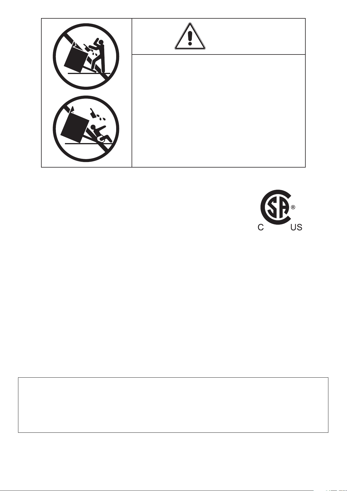
• ALL RANGES CAN TIP
• INJURY TO PERSON COULD RESULT
• INSTALL ANTI-TIP DEVICE PACKED
WITH RANGE
• SEE INSTALLATION INSTRUCTIONS
IMPORTANT - PLEASE READ AND FOLLOW
WARNING
✓ Before beginning, please read these instructions completely and carefully.
✓ Do not remove permanently affixed labels, warnings, or plates from the product. This
may void the warranty.
✓ Please observe all local and national codes and ordinances.
✓ Please ensure that this product is properly grounded.
✓ The electrical plug should always be accessible.
✓ The installer should leave these instructions with the consumer who should retain
for local inspector's use and for future reference.
Electrical installation must be in accordance with the National Electrical Code, ANIS/
NFPA70 - latest edition and/or local codes.
IN CANADA: Electrical installation must be in accordance with the current CSA C22.1
Canadian Electrical Codes Part 1 and/or local codes.
This appliance is designed and manufactured solely for the cooking of domestic (household)
food and in not suitable for any none domestic application and therefore should not be used
in a commercial environmement.
The appliance guarantee will be void if the appliance is used within a none domestic
environnement i.e. a semi commercial, commercial or communal environment.
2
INSTALLATION INSTRUCTIONS
WARNING!
THIS APPLIANCE HAS TO BE INSTALLED BY A QUALIFIED INSTALLER.
Installation must conform with local codes.
Improper installation, adjustment, alteration, services, or maintenance can cause injury or property damage. Consult a
qualified installer or a service agent.
IMPORTANT: The use of suitable protective clothing/gloves is recommended when handling, installing of this appliance.
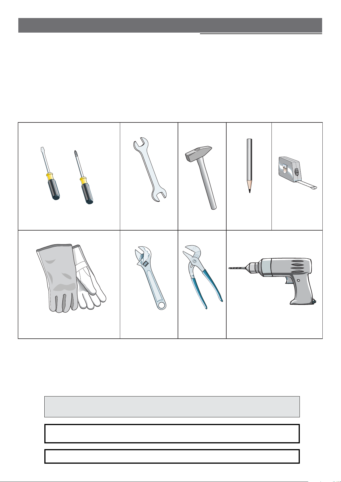
TOOLS NEEDED FOR INSTALLATION (NOT SUPPLIED WITH THE APPLIANCE)
Screwdriver
Suitable protective
gloves
Wrench
Adjustable
wrench
Hammer
Adjustable
pliers
Tape
measurePencil
Drill
This range is supplied with a protective film on steel and aluminium parts.
This film must be removed before installing/using the appliance.
FOR INSTALLER ONLY
THIS RANGE IS FOR RESIDENTIAL USE ONLY
3

GENERAL INFORMATION
WARNING!!
WARNING!!
1. This appliance shall not be used for space heating. This
information is based on safety considerations.
2. AlI openings in the wall behind the appliance and in the floor
under the appliance shall be sealed.
3. Keep appliance area clear and free from combustible
materials, gasoline, and other flammable vapors.
4. Do not obstruct the flow of ventilation air.
5. Disconnect the electrical supply to the appliance before
servicing.
6. When removing appliance for cleaning and/or service;
A. Disconnect AC power supply.
B. Carefully remove the range by pulling outward.
CAUTION: Range is heavy; use care in handling.
7.
Electrical Requirement
Electrical installation should comply with national and local
codes.
8. The misuse of oven door (e.g. stepping, sitting, or leaning
on them) can result in potential hazards and/or injuries.
ELECTRICAL GROUNDING INSTRUCTIONS
The range must be electrically grounded in accordance
with local codes or, in the absence of local codes, with
the National Electrical Code, ANSI/NFPA No. 70-latest
edition, in Canada Canadian Electrical Code.
Installation should be made by a Iicensed electrician.
FOR PERSONAL SAFETY, THIS APPLIANCE MUST BE
PROPERLY GROUNDED.
If an external electrical source is utilized, the installation must
be electrically grounded in accordance with local codes or, in
the absence of local codes, with the national Electrical Code,
ANSI/NFPA 70.
This appliance is equipped with a four-prong grounding plug
(NEMA 14-50P) for your protection against shock hazard and
should be plugged directly into a properly grounded socket.
Do not under any circumstances cut or remove the fourth
(ground) prong from the power plug.
REPLACEMENT PARTS
Only authorized replacement parts may be used in performing
service on the range. Replacement parts are available from
factory authorized parts distributors. Contact the nearest parts
distributor in your area.
9. When installing or removing the range for service, a rolling
lift jack should be used. Do not push against any of the
edges of the range in an attempt to slide it into or out of
the installation. Pushing or pulling a range (rather than using
a lift jack) also increases the possibility of bending the leg
spindles or the internal coupling connectors.
4
installation
PROXIMITY TO SIDE CABINETS
1. This range may be installed directly adjacent to existing 36" (914 mm) high base
cabinets.
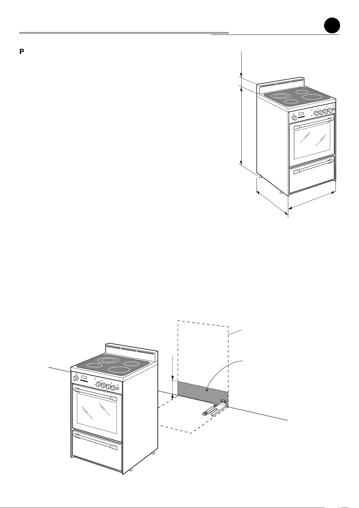
Range dimensions:
• width: 23” 7/8 (606.5 mm)
• depth: 24” 11/64 (614.1 mm)
• height (without backguard): MIN 35” 17/32 (902.5 mm) - MAX 36” 7/
32 (920 mm)
• backguard (height): 4” 7/16 (113 mm)
The electric cord with 4-prong ground plug (NEMA 14-50P) has a length of 72"
±1"1/2 (1830 mm ±38 mm).Grounded outlet should be located 7” 9/32 (185 mm)
from the floor and from the rear left to the rear right side of the range.
2. The range CANNOT be installed directly adjacent to sidewalls, tall cabinets, tall
appliances, or other side vertical surfaces above 36” (914 mm) high.
There must be a minimum of 3” (76 mm) side clearance from the range to such
combustible surfaces TO THE LEFT above the 36” (914 mm) high countertop; or
there must be a minimum of 3” (76 mm) side clearance from the range to such
combustible surfaces TO THE RIGHT above the 36” (914 mm) high countertop.
IMPORTANT: One side (left or right) above the 36” (914 mm) high countertop
must always be kept clear.
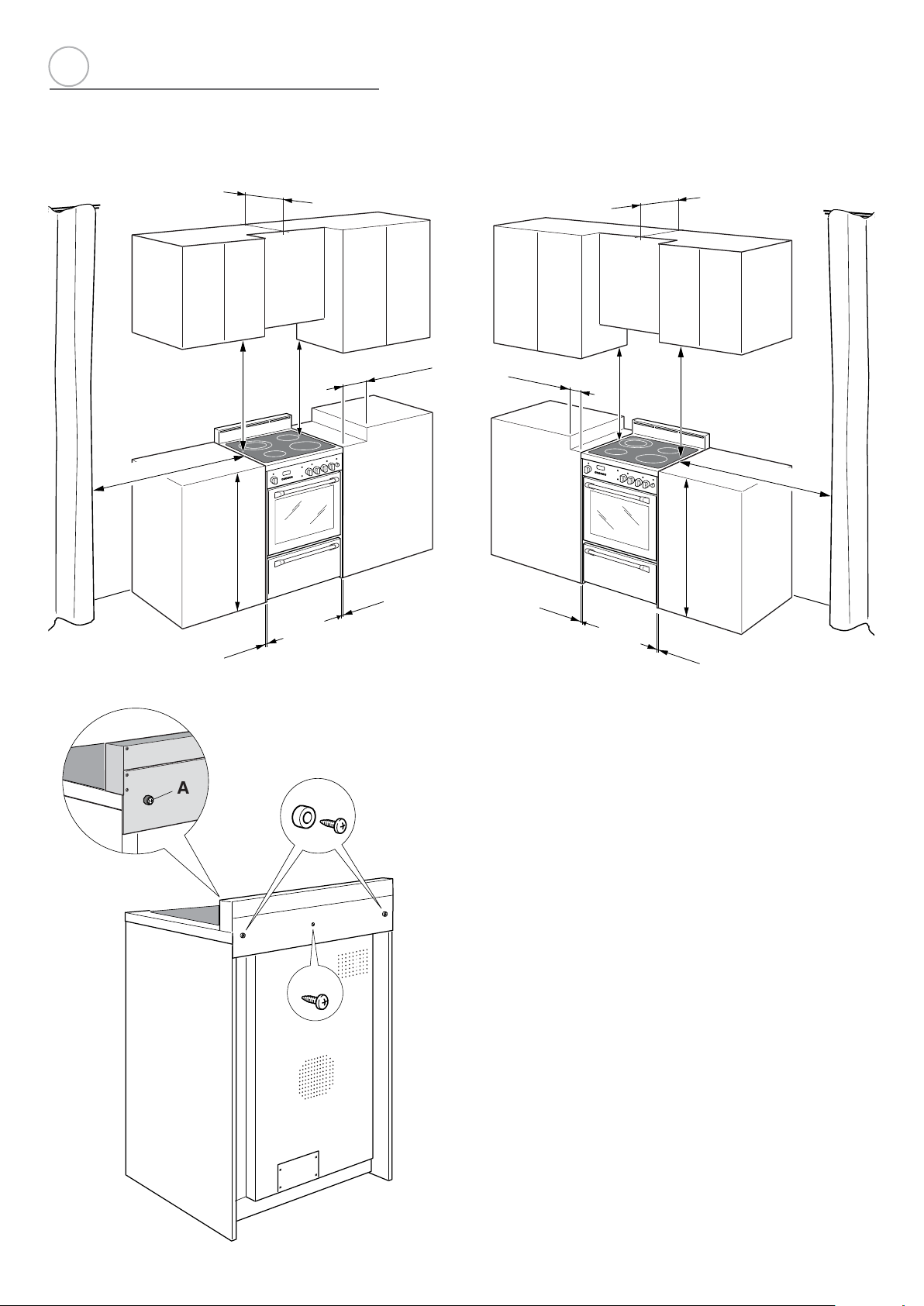
3. The maximum upper cabinet depth recommended is 13” (330 mm). Wall cabinet
above the range must be a minimum of 30” (762 mm) above the countertop for a
width of minimum 24” (609.6 mm): it has to be centred with the range. Side wall
cabinets above the range must be a minimum of 18” (457 mm) above the countertop.
4" 7/16
(113 mm)
MAX 36" 7/32 (920 mm)
MIN 35" 17/32 (902.5 mm)
24" 11/64
(614.1 mm)
23" 7/8
(606.5 mm)
Fig. 1.1
1
A
ELECTRIC CONNECTION
(185 mm)
7" 9/32
Dotted line showing the position
of the range when installed
Area for electric connection
Fig. 1.2
5
A
1
a
PROXIMITY TO SIDE CABINETS
Fig. 1.3
20" min. (500 mm)
13" max. (330 mm)
18" min.
30" min.
(762 mm)
36"
(914 mm)
0"
(0 mm)
(457 mm)
min. (76 mm)
3"
0"
(0 mm)
3"
min. (76 mm)
0"
(0 mm)
13" max. (330 mm)
18" min.
(457 mm)
30" min.
(762 mm)
36"
(914 mm)
0"
(0 mm)
20" min. (500 mm)
Fig. 1.4
A
ASSEMBLING THE BACKGUARD
It is mandatory to install the backguard
Assemble the backguard as shown in figure 1.5:
• Screw the 2 screws “A” interposing the spacers.
B
6
Fig. 1.5
• Screw the central screw “B”.
 Loading...