

Fisher & Paykel DD60SCHW7, DD60SCB7, DD60SCHB7, DD60SCM7, DD60SDFX7 Installation Instructions Manual
...
NZ AU GB IE
590200D 04.13
DD60S 7 & DD60ST 7 models
INSTALLATION INSTRUCTIONS
DishDrawer
TM
dishwasher
2
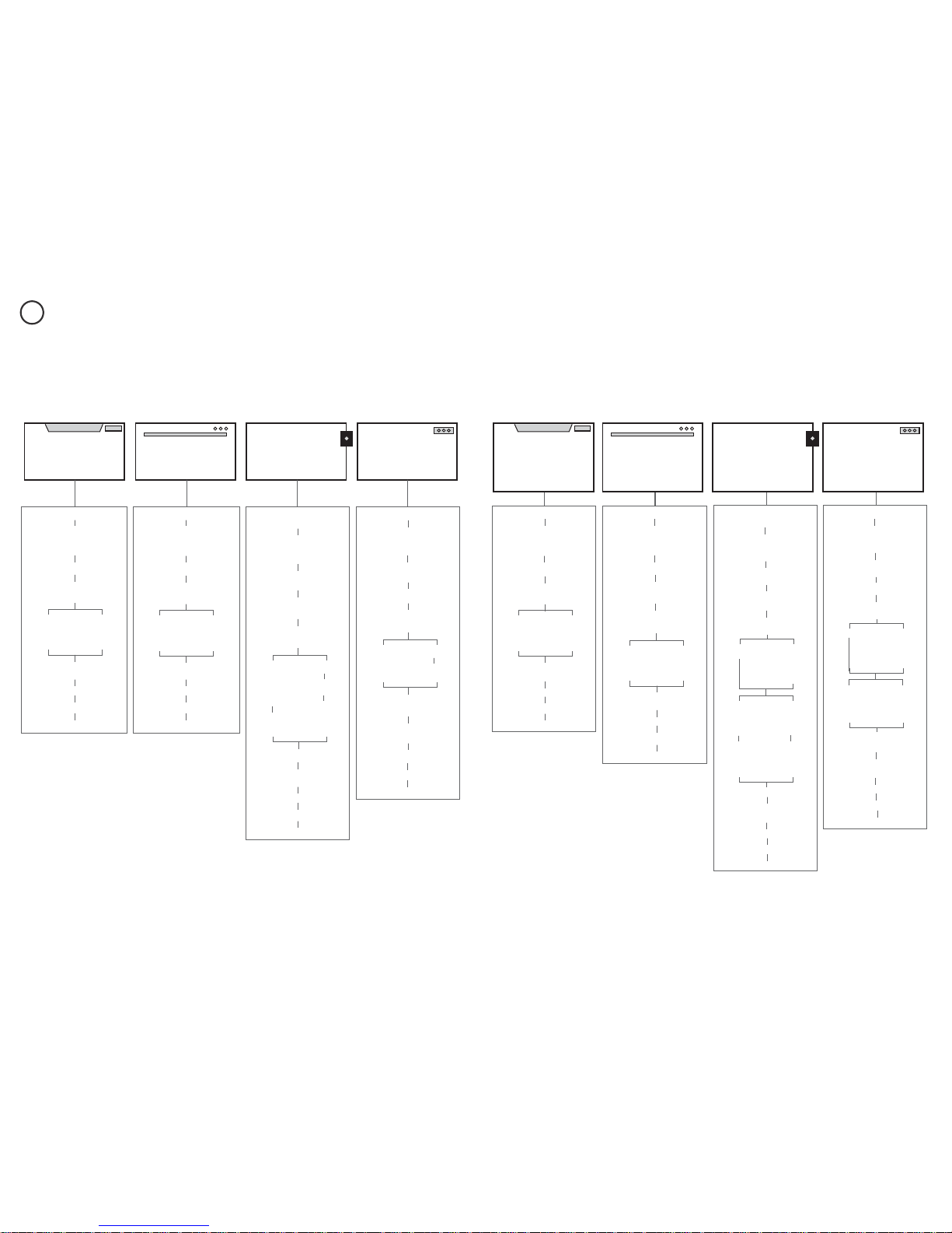
FOLLOW THE INSTALLATION SEQUENCE RELEVANT TO YOUR MODEL
1
DD60SHI7
DD60SLI7
(not available in GBIE, only NZAU)
Classic
PRODUCT & CABINETRY
DIMENSIONS
(STANDARD HEIGHT)
PRODUCT & CABINETRY
DIMENSIONS
(STANDARD HEIGHT)
PRODUCT & CABINETRY
DIMENSIONS
(STANDARD HEIGHT)
PRODUCT & CABINETRY
DIMENSIONS
(TALL HEIGHT)
PRODUCT & CABINETRY
DIMENSIONS
(TALL HEIGHT)
PRODUCT & CABINETRY
DIMENSIONS
(TALL HEIGHT)
DD60SC(H)X7
DD60SC(H)W7
DD60SDF(H)X7
DD60SDFM7
DD60SC(H)B7
DD60SCM7
Designer
DD60SI7
DD60SC(H)TX7
DD60SC(H)TW7
DD60SDF(H)TX7
DD60SDFTM7
DD60SC(H)TM7
Integrated with remote control Integrated with badge control Integrated with remote control Integrated with badge control
Classic
Designer
DD60STI7 DD60SHTI7
CUSTOM FRONT
PANEL CALCULATIONS
CUSTOM FRONT
PANEL CALCULATIONS
PARTS SUPPLIED
CAVITY PREPARATION
MAXIMUM DISTANCE OF HOSES
& CORD FROM CHASSIS EDGE
SECURE WITHOUT
DRAWER REMOVAL
RECOMMENDED
METHOD (a)
ALTERNATIVE
METHOD (b)
SECURE BY
DRAWER REMOVAL
CHOOSE
DRAINAGE OPTION
FINAL CHECKLIST
CONNECT TO WATER & ELECTRICITY
TROUBLESHOOTING
FINAL CHECKLIST
CONNECT TO WATER & ELECTRICITY
PARTS SUPPLIED
CAVITY PREPARATION
MAXIMUM DISTANCE OF HOSES
& CORD FROM CHASSIS EDGE
PARTS SUPPLIED +
EXTERNAL VENTING KIT
PARTS SUPPLIED +
EXTERNAL VENTING KIT
CAVITY PREPARATION
ATTA CH
CAVITY BRACKET
MAXIMUM DISTANCE OF HOSES
& CORD FROM CHASSIS EDGE
SECURE WITHOUT
DRAWER REMOVAL
RECOMMENDED
METHOD (a)
ALTERNATIVE
METHOD (b)
SECURE BY
DRAWER REMOVAL
CHOOSE
DRAINAGE OPTION
FINAL CHECKLIST
TROUBLESHOOTING
FINAL CHECKLIST
TROUBLESHOOTING
SECURE WITHOUT
DRAWER REMOVAL
RECOMMENDED
METHOD (a)
ALTERNATIVE
METHOD (b)
SECURE BY
DRAWER REMOVAL
PARTS SUPPLIED
CAVITY PREPARATION
MAXIMUM DISTANCE OF HOSES
& CORD FROM CHASSIS EDGE
SECURE WITHOUT
DRAWER REMOVAL
RECOMMENDED
METHOD (a)
ALTERNATIVE
METHOD (b)
SECURE BY
DRAWER REMOVAL
CHOOSE
DRAINAGE OPTION
FINAL CHECKLIST
CONNECT TO WATER & ELECTRICITY
CHOOSE
DRAINAGE OPTION
TROUBLESHOOTING
PARTS SUPPLIED
CAVITY PREPARATION &
EXTERNAL VENTING
MAXIMUM DISTANCE OF HOSES
& CORD FROM CHASSIS EDGE
FOLLOW STEPS
FOR THE
EXTERNAL
VENTING KIT
INSTALL THE FRONT PANEL
INSTALL THE FRONT PANEL
CONNECT TO WATER & ELECTRICITY
CONNECT TO WATER & ELECTRICITY
CHOOSE
DRAINAGE OPTION
CONNECT TO WATER & ELECTRICITY
CHOOSE
DRAINAGE OPTION
CONNECT TO WATER & ELECTRICITY
CHOOSE
DRAINAGE OPTION
TROUBLESHOOTING
FINAL CHECKLIST
TROUBLESHOOTING
FOLLOW STEPS
FOR THE
EXTERNAL
VENTING KIT
SECURE WITHOUT
DRAWER REMOVAL
RECOMMENDED
METHOD (a)
ALTERNATIVE
METHOD (b)
SECURE BY
DRAWER REMOVAL
480 mm CAVITY
ONLY - ATTACH
CAVITY BRACKET
FINAL CHECKLIST
CHOOSE
DRAINAGE OPTION
CONNECT TO WATER & ELECTRICITY
TROUBLESHOOTING
SECURE WITHOUT
DRAWER REMOVAL
RECOMMENDED
METHOD (a)
ALTERNATIVE
METHOD (b)
SECURE BY
DRAWER REMOVAL
FOLLOW STEPS
FOR THE
EXTERNAL
VENTING KIT
FOLLOW STEPS
FOR THE
EXTERNAL
VENTING KIT
CAVITY PREPARATION &
EXTERNAL VENTING
MAXIMUM DISTANCE OF HOSES
& CORD FROM CHASSIS EDGE
456mm CAVITY
480mm CAVITY
PRODUCT & CABINETRY
DIMENSIONS
(TALL HEIGHT)
CUSTOM FRONT
PANEL CALCULATIONS
PARTS SUPPLIED
480 mm CAVITY
ONLY - ATTACH
CAVITY BRACKET
FINAL CHECKLIST
TROUBLESHOOTING
SECURE WITHOUT
DRAWER REMOVAL
RECOMMENDED
METHOD (a)
ALTERNATIVE
METHOD (b)
SECURE BY
DRAWER REMOVAL
CAVITY PREPARATION
MAXIMUM DISTANCE OF HOSES
& CORD FROM CHASSIS EDGE
456mm CAVITY 480mm CAVITY
PRODUCT & CABINETRY
DIMENSIONS
(STANDARD HEIGHT)
CUSTOM FRONT
PANEL CALCULATIONS
PARTS SUPPLIED
CAVITY PREPARATION
MAXIMUM DISTANCE OF HOSES
& CORD FROM CHASSIS EDGE
INSTALL THE FRONT PANEL
& BADGE CONTROLS
INSTALL THE FRONT PANEL
& BADGE CONTROLS
SECURE WITHOUT
DRAWER REMOVAL
RECOMMENDED
METHOD (a)
ALTERNATIVE
METHOD (b)
SECURE BY
DRAWER REMOVAL
STANDARD HEIGHT SINGLE MODELS
TALL HEIGHT SINGLE MODELS
ONLY AVAILABLE IN NZ AU ONLY AVAILABLE IN NZ AUONLY AVAILABLE IN GB IE ONLY AVAILABLE IN GB IE
3
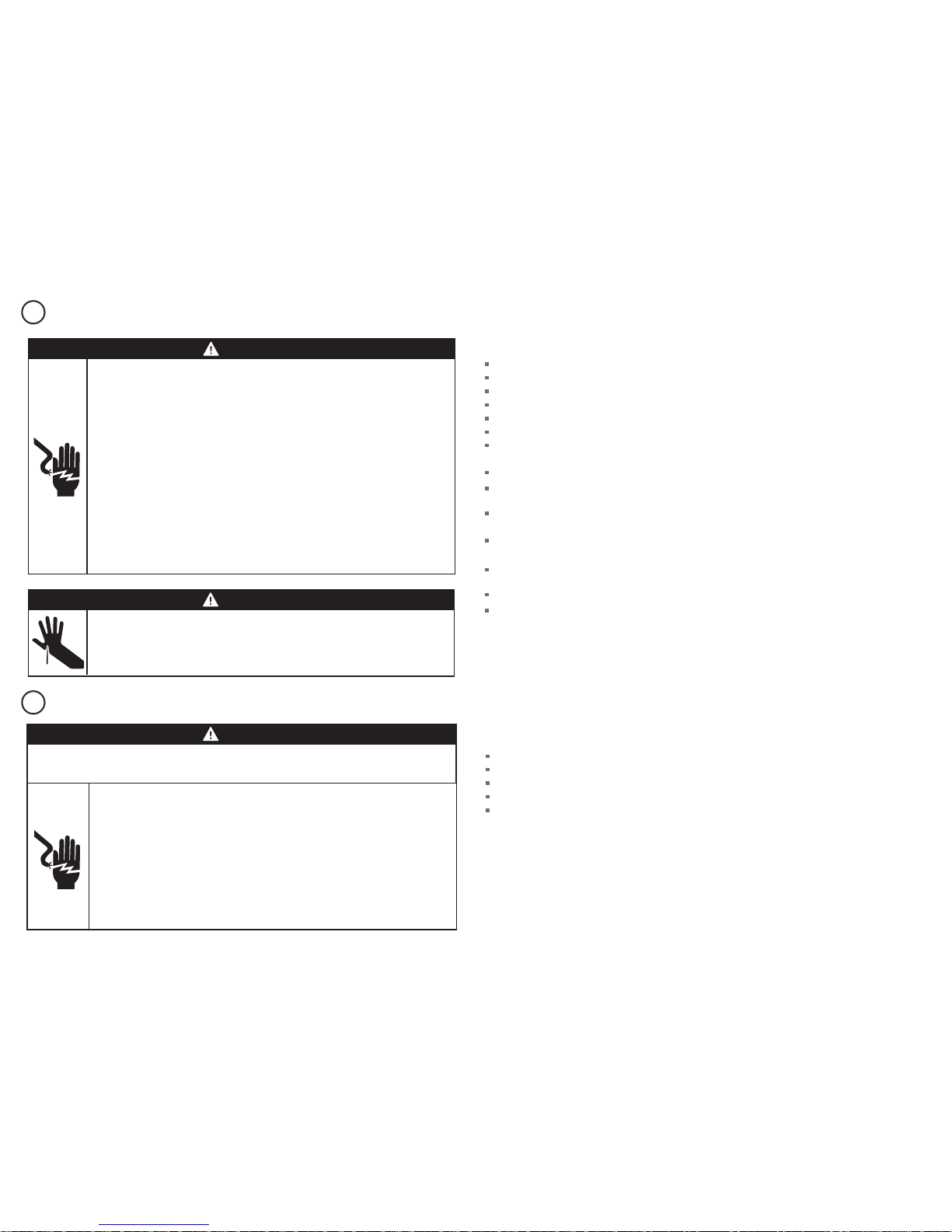
SAFETY AND WARNINGS - ALL MODELS
ADDITIONAL SAFETY AND WARNINGS - INTEGRATED MODELS ONLY
2a
2b
WARNING!
Electrical shock hazard
Before installing the dishwasher, remove the house fuse or open the circuit
breaker.
This appliance must be earthed. In the event of a malfunction or breakdown,
earthing will reduce the risk of electric shock by providing a path of least
resistance for electric current. This appliance is equipped with a cord having an
equipment-earthing conductor and an earthing plug. The plug must be plugged
into an appropriate outlet that is installed and earthed in accordance with all
local codes and ordinances. WARNING- Improper connection of the equipmentearthing conductor can result in a risk of electric shock. Check with a qualified
electrician or service representative if you are in doubt as to whether the
appliance is properly earthed.
Do not modify the power supply plug provided with the appliance - if it will not
fit the outlet, have a proper outlet installed by a qualified electrician. Do not use
an extension cord, adapter plug or multiple outlet box.
Failure to follow this advice may result in electrical shock or death.
WARNING!
Cut hazard
Take care - panel edges are sharp.
Failure to use caution could result in injury or cuts.
IMPORTANT SAFETY INSTRUCTIONS!
Installation of this dishwasher requires basic mechanical and electrical skills.
Be sure to leave these Instructions with the Customer.
Installation must comply with your local building and electricity regulations.
At the completion of the dishwasher installation, the Installer must perform the Final Checklist.
Remove all packaging materials supplied with the dishwasher.
This dishwasher is manufactured for indoor use only.
Ensure all water connections are turned OFF. It is the responsibility of the plumber and
electrician to ensure that each installation complies with all Codes and Regulations.
The dishwasher MUST be installed to allow for future removal from the enclosure if service is required.
The switched power outlet must be outside the dishwasher cavity, so that it is accessible after
installation.
Care should be taken when the appliance is installed or removed to reduce the likelihood of damage to
the power supply cord and hoses.
If the dishwasher is to be relocated from one installation to another it must be kept upright to avoid
damage from water spillage.
Make sure only new hoses are used for connection (supplied with the dishwasher). Old hoses should
not be reused.
Failure to install the dishwasher correctly could invalidate any warranty or liability claims.
If the product is installed in a motor vehicle, boat or similar mobile facility, you must bring the vehicle,
boat or mobile facility containing the product to the service shop at your expense or pay the service
technician’s travel to the location of the product.
SAVE THESE INSTRUCTIONS
IMPORTANT SAFETY INSTRUCTIONS!
Read these instructions completely and carefully.
Ensure the product is not plugged in.
Installation of custom panels requires basic mechanical and electrical skills.
Installation must comply with your local building and electricity regulations.
Failure to install the custom panels correctly could invalidate any warranty or liability claims.
SAVE THESE INSTRUCTIONS
Electrical Shock Hazard
WARNING: To reduce the risk of electrical shock, fire, or injury to persons, the
installer must ensure that the dishwasher is completely enclosed at the time of
installation.
Before fitting the front panels and connecting the integrated badges (where
present), the installer must ensure that the dishwasher is disconnected from the
power supply.
After installing the front panel, the installer must ensure that the following
components are electrically earthed: the panel bracket, the integrated badge
(where present) and any custom metal component (e.g. handle) that extends
past the rubber seal.
Failure to follow these warnings may result in electrical shock, injury or fire.
WARNING!
Fitting integrated front panels requires access to electrical service areas.
This work must be performed and certified by a qualified electrical service technician.
4
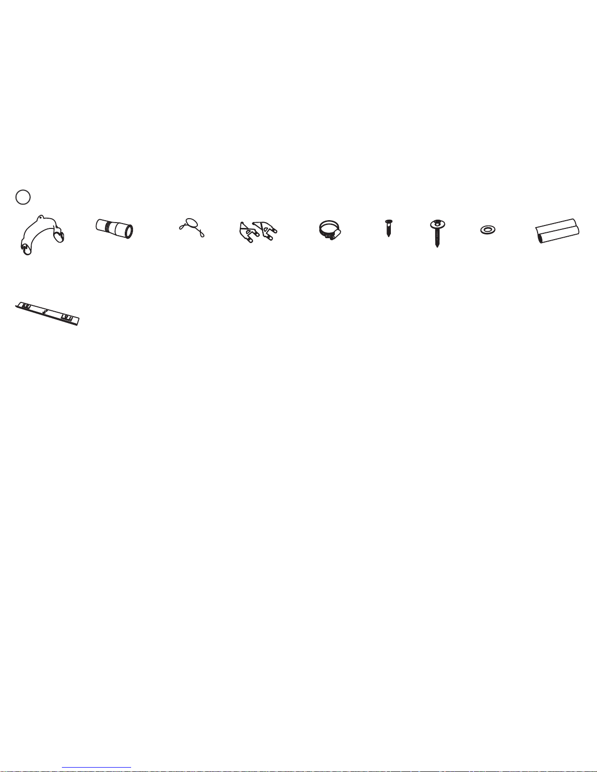
PARTS SUPPLIED - ALL MODELS
3a
If the Drain hose supplied is not long enough to reach your services, you must use a Drain Hose Extension Kit P/N 525798 which will extend the drain hose by 3.6m.
The kit is available from the nearest Fisher & Paykel Authorised Service Centre or through our local website listed at the end of this document.
Clamp (1)
(for securing
Drain hose joiner)
Wire clip (1)
(for securing
Drain hose joiner)
Phillips
16 mm
screws (7)
38 mm
bottom
fixing screws
& metal
washers (2)
Drain hose
support (1)
Moisture
protection
tape (1)
(to prevent
moisture damage)
Cavity bracket kit (1)
supplied with Tall height
Designer and Integrated
models only
Drain hose
joiner (1)
Rubber
washer for
inlet hose (1)
(comes already
fitted)
Side mounting
bracket kit
(A and B) (2)
OPTIONAL
5
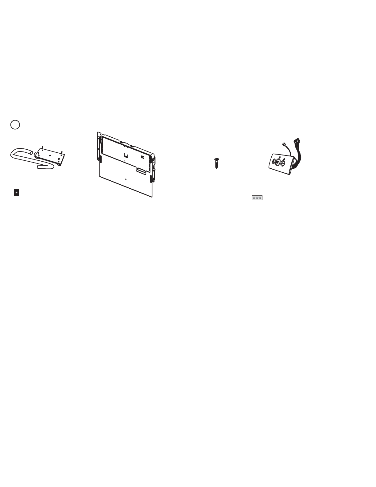
ADDITIONAL PARTS SUPPLIED WITH INTEGRATED MODELS
3b
External Venting kit (1)
supplied with Integrated
models with remote only
Panel mounting
screws (6)
Panel bracket (1)
(attached to
product)
Integrated rectangular badge (1)
(Satin chrome supplied)
supplied with Integrated models
with badge only
6
4
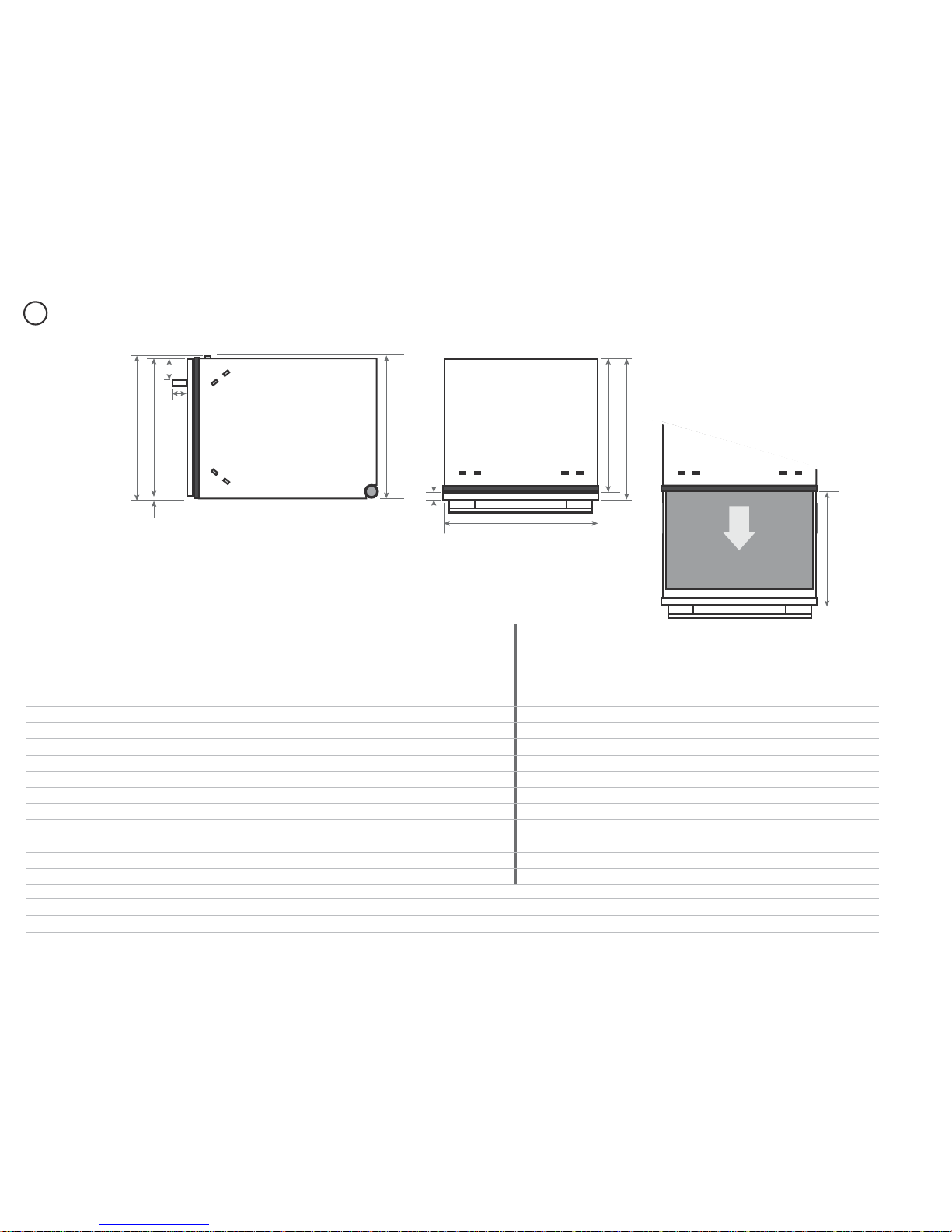
PRODUCT DIMENSIONS
AHI
J
K
Side
Plan
G
F
B
CD
E
Product dimensions (mm)
STANDARD HEIGHT MODELS TALL HEIGHT MODELS
Classic
Designer
Integrated
Remote
control
Integrated
Badge
control
Classic
Designer
Integrated
Remote
control
456 mm cavity
Integrated
Badge
control
456 mm cavity
Integrated
Remote
control
480 mm cavity
Integrated
Badge
control
480 mm cavity
A
overall height1 of product (incl. front panel height) 410 410 410 410 454 478
2
454 454 478
2
478
2
B
overall width of product 599 599 599 599 599 599 599 599 599 599
C
overall depth of product (excl. handle) 582 571 571
3
571
3
582 571 571
3
571
3
571
3
571
3
D
depth of chassis (to back of front panel) 553 553 553 553 553 553 553 553 553 553
E
maximum extension of drawer (excl. handle) 556 545 545
3
545
3
556 545 545
3
545
3
545
3
545
3
F
depth of front panel (excl. handle) 29 18 16-20 16-20 29 18 16-20 16-20 16-20 16-20
G
height1 of chassis 410 410 410 410 454 454 454 454 454 454
H
depth of handle n/a 41 n/a n/a n/a 41 n/a n/a n/a n/a
I
height of front panel 394 398 4084min. 398 438 470 4525min. 442 4765min. 470
J
height of ventilation gap below front panel 7 8 min. 2 min. 8 7 8 min. 2 min. 8 min. 2 min. 8
K
height from top of handle to top of front panel n/a 64 n/a n/a n/a 64 n/a n/a n/a n/a
1
includes 2mm high bracket slots 2Includes cavity bracket 3Assuming front panel thickness of 18 mm
4
Recommended for a 2 mm ventilation gap below panel, if cavity height is 412 mm 5Recommended for a 2 mm ventilation gap below panel

7
5
CABINETRY DIMENSIONS
min.
412mm
456mm 480mm
LL L
dishwasher dishwasher dishwasher
Standard height models
Tall height Classic models
Tall height Integrated models
Compact
Oven
Single
Oven
Tall height Designer models
Plan
Side
L
N
M
Cavity height options allow you to match dishwasher with your cabinetry or companion products
Minimum clearances from adjacent cabinetry
You may choose to install Tall height Integrated
models into either a 456 mm or a 480 mm high cavity.
Note: the minimum height of the custom drawer front
panel will also be different for these two options.
Cabinetry dimensions (mm)
STANDARD HEIGHT MODELS TALL HEIGHT MODELS
Classic
Designer
Integrated
Remote
control
Integrated
Badge
control
Classic
Designer
Integrated
Remote
control
456 mm cavity
Integrated
Badge
control
456 mm cavity
Integrated
Remote
control
480 mm cavity
Integrated
Badge
control
480 mm cavity
L
inside height of cavity min. 412 min. 412 min. 412 min. 412 456 480 456 456 480 480
M
inside width of cavity 600 600 600 600 600 600 600 600 600 600
N
inside depth of cavity min. 560 min. 560 min. 560 min. 560 min. 560 min. 560 min. 560 min. 560 min. 560 min. 560
min. 13 mm
clearance
from a corner
min. 2 mm
clearance
to adjacent
cupboard door
 Loading...