

Fisher & Paykel DishDrawer DD24DA, DD24DA, DD24DCT Installation Instructions Manual

DishDrawerTM dishwasher
DD24DA
models
US CA
INSTALLATION INSTRUCTIONS
590665B 03.15
www.fisherpaykel.com
2
IMPORTANT!
SAVE THESE INSTRUCTIONS
The models shown in this installation guide may not be available in all markets and are subject to change at any time. For current details about model and specification availability in your country, please go to our
website www.fisherpaykel.com or contact your local Fisher & Paykel dealer.
1 SAFETY AND WARNINGS
IMPORTANT SAFETY INSTRUCTIONS
Installation of this dishwasher requires basic mechanical and electrical skills.
Be sure to leave these Instructions with the Customer.
Installation must comply with your local building, electricity, and plumbing regulations.
At the completion of the dishwasher installation, the Installer must perform the Final
Checklist.
Remove all packaging materials supplied with the dishwasher.
This dishwasher is manufactured for indoor use only.
Ensure all water connections are turned OFF. It is the responsibility of the plumber and
electrician to ensure that each installation complies with all Codes and Regulations.
The dishwasher MUST be installed to allow for future removal from the enclosure if
service is required.
The switched power outlet must be outside the dishwasher cavity, so that it is accessible
after installation.
Care should be taken when the appliance is installed or removed to reduce the likelihood
of damage to the power supply cord and hoses.
If the dishwasher is to be relocated from one installation to another it must be kept
upright to avoid damage from water spillage.
Make sure only new hoses are used for connection (supplied with the dishwasher). Old
hoses should not be reused.
Failure to install the dishwasher correctly could invalidate any warranty or liability claims.
If the product is installed in a motor vehicle, boat or similar mobile facility, you must
bring the vehicle, boat or mobile facility containing the product to the service shop at
your expense or pay the service technician’s travel to the location of the product.
This dishdrawer is intended for connection to the hot-water supply.
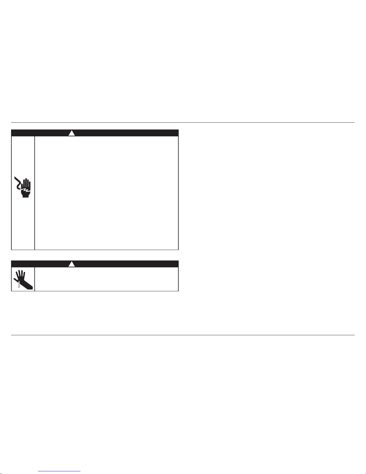
WARNING!
Electrical Shock Hazard
Before installing the dishwasher, remove the house fuse or open the circuit
breaker. If permanently connecting the dishwasher, be sure the power is
isolated and the dishwasher unplugged.
GROUNDING INSTRUCTIONS
This appliance must be grounded. In the event of a malfunction or breakdown,
grounding will reduce the risk of electric shock by providing a path of least
resistance for electric current. This appliance is equipped with a cord having
an equipment-grounding conductor and a grounding plug. The plug must be
plugged into an appropriate outlet that is installed and grounded in
accordance with all local codes and ordinances. WARNING - Improper
connection of the equipment-grounding conductor can result in a risk of
electric shock. Check with a qualified electrician or service representative if
you are in doubt as to whether the appliance is properly grounded.
If the dishwasher is installed as a permanently connected appliance:
GROUNDING INSTRUCTIONS - This appliance must be connected to a
grounded metal, permanent wiring system, or an equipment-grounding
conductor must be run with the circuit conductors and connected to the
equipment-grounding terminal or lead on the appliance.
Do not modify the power supply plug provided with the appliance - if it will
not fit the outlet, have a proper outlet installed by a qualified electrician. Do
not use an extension cord, adapter plug or multiple outlet box.
Failure to follow this advice may result in electrical shock or death.
WARNING!
Cut Hazard
Take care - panel edges are sharp.
Failure to use caution could result in injury or cuts.
!
!
3
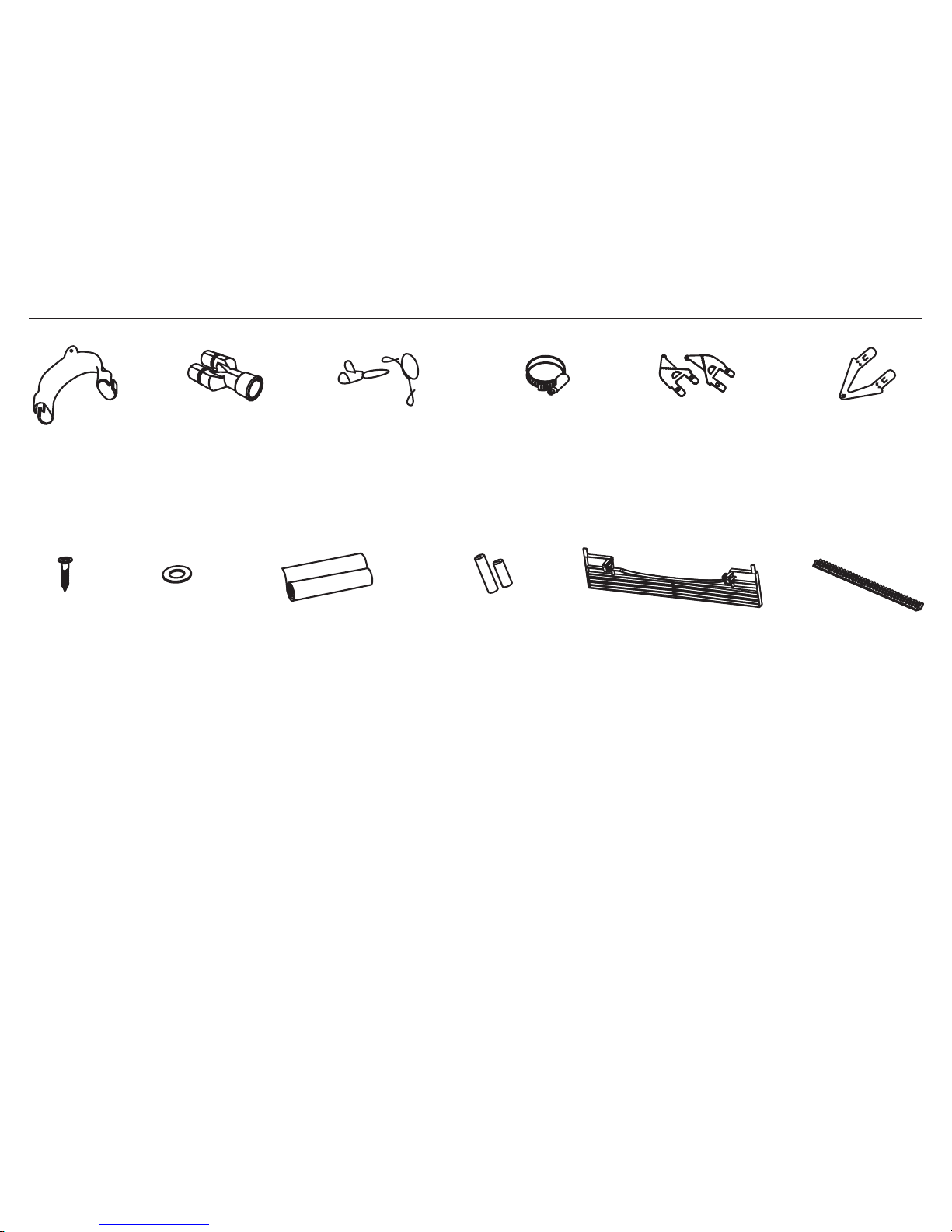
2 PARTS SUPPLIED
If the Drain hoses supplied are not long enough to reach your services, you must use a Drain Hose Extension Kit P/N 525798 which will extend the drain hoses by 11’ 10” (3.6m).
The kit is available from the nearest Fisher & Paykel Authorized Service Center, or Toll free 1.888.936.7872 or www.fisherpaykel.com
Clamp (1)
(for securing
Drain hose joiner)
Wire clip (2)
(for securing
Drain hose joiner)
Phillips
5⁄8” (16 mm)
screws (9)
Drain hose
support (1)
Moisture protection
tape (1)
(to prevent moisture
damage to cabinetry)
Drain hose
joiner (1)
Top
mounting
brackets (2)
OPTIONAL
Prefinished
toekick (1)
Edge Protector (1)
(If the services hole
is through a metal
partition, the hole must
be protected with the
Edge Protector supplied
to prevent damage to the
power cord or hoses.)
Rubber washer
for inlet hose (1)
(comes already
fitted)
Hexagonal
socket for feet
adjustment (2)
(long & short)
Side mounting
bracket kit
(A and B) (2)
OPTIONAL
4
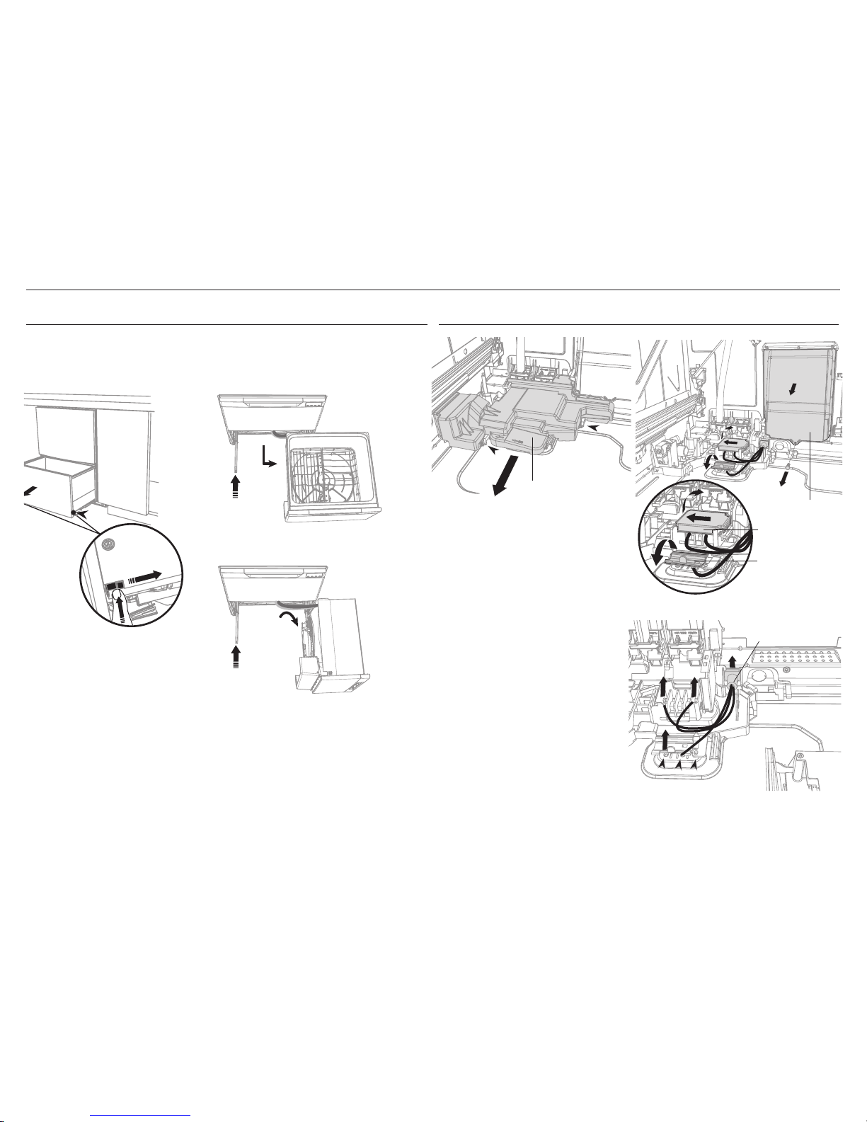
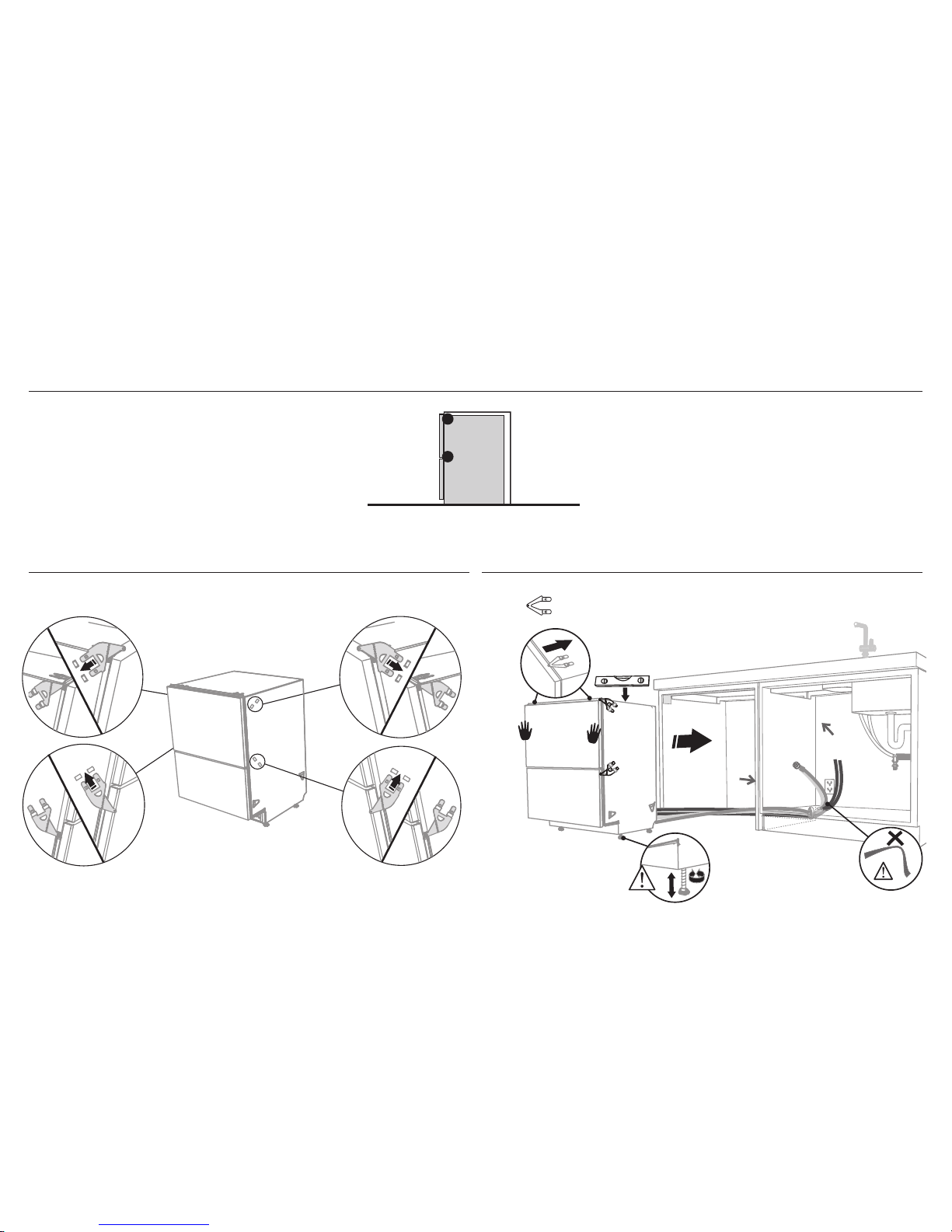
3 OPTIONALLY HARD WIRING PRIOR TO INSTALLATION
3-A REMOVE THE LOWER DRAWER 3-B REMOVE THE ACCESS COVER & REMOVE POWER
Access cover
Clip
Clip
Electronics
module
Terminal
Block cover
Remove existing
power cord
1 With a flat-bladed screwdriver, push
in the clips and slide out the access
cover.
2 Unscrew the electronics module
cover.
3 Carefully pull out the electronics
module and rest on the chassis base
out of the way.
4 With a screwdriver, unclip the plastic
harness cover and hinge open.
5 Slide the terminal block cover
sideways to unlock and hinge open
to access the terminal block.
6 Unscrew the Live, Neutral and Earth
wires as shown.
7 Unscrew the three screws on the
base as shown and remove the cord
from the product.
1
1
2
3
4
5
6
7
7
1
2
4
4
3
3
4” (100 mm)
To prevent kinked hoses
Either sit the drawer down on the left
hand side (recommended) or rotate the
drawer clockwise, resting it on its side after
removal.
Press the release tabs
in on either side and
push back to release
drawer from runners.
Lift drawer off runners.
Push drawer
runners back in
on either side.
Push drawer
runners back in
on either side.
Sit the drawer down
Rotate the drawer
clockwise (max. 90
o
)
and rest on side.
5
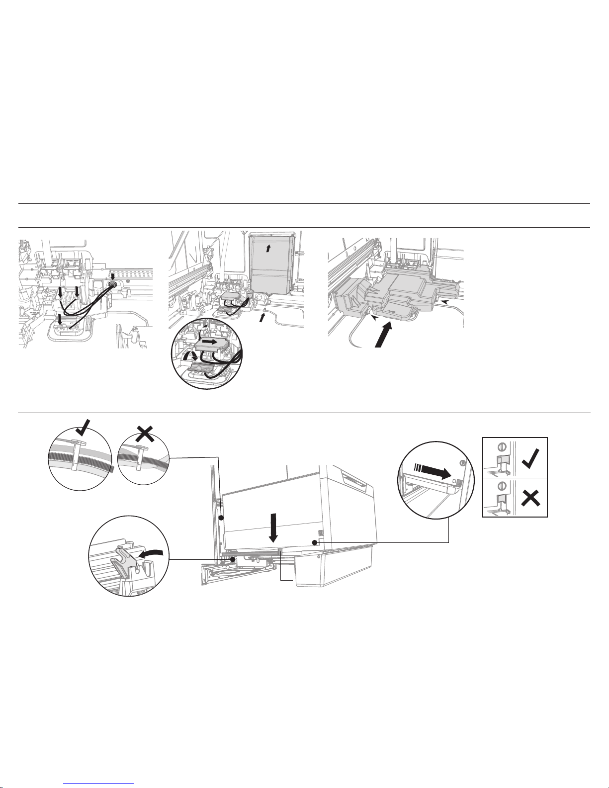
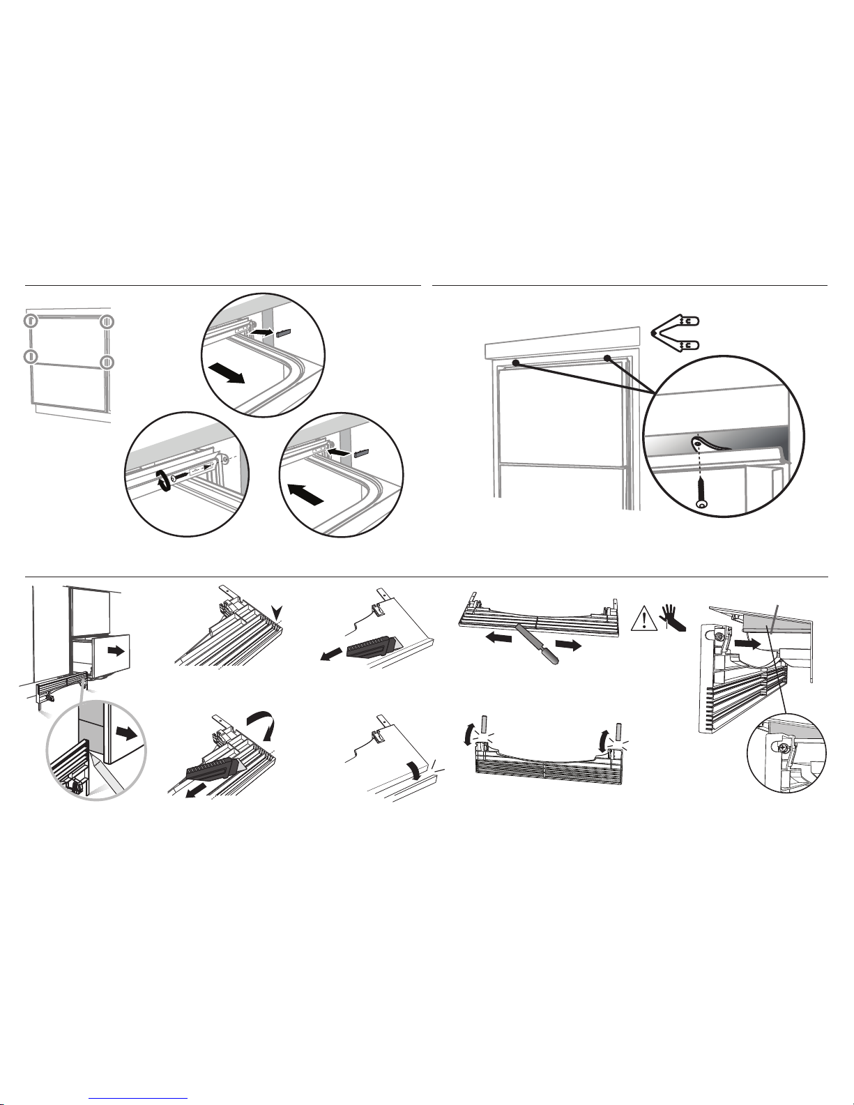
3 OPTIONALLY HARD WIRING PRIOR TO INSTALLATION
IMPORTANT!
Ensure the mains wires are routed
UNDERNEATH all other harness
wiring from the electronics module.
3-D REFIT THE DRAWER ONTO THE RUNNERS & CLOSE
3-C TERMINATE MAINS WIRING AS SHOWN AND REPLACE MODULE AND COVERS
4” (100 mm)
Pull the release tabs forward on both
sides 4” (100 mm). Ensure the tabs are
fully pulled forward and click into place.
8
9
10
11
12
13
14
8 Fit a suitable cable clamp for the
conduit through the metal knockout.
Ensure wiring is routed through or
under under housing ribs.
9 Screw down the Live, Neutral and
Earth wires correctly.
10 Push the plastic harness cover back
over. It should clip back into place
11 Fold down and slide back the
terminal block cover.
12 Refit the electronics module back
into position, being careful of wiring.
13 Replace the screw securing the
electronics module.
14 Slide the access cover back,
ensuring the 2 clips shown are fully
locked in place.
NOTE: Use copper conductors
only.
1
2
3
4
Before refitting the
drawer, ensure the hoses
are not twisted and the
latches at the rear of
each drawer runner are
facing forward.
Lift or rotate counter-clockwise the
drawer back onto the drawer runners
on either side.
Release tab
6
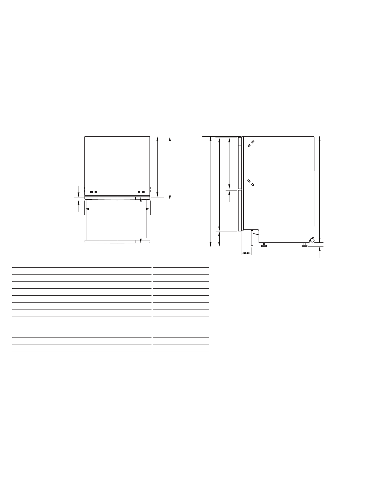
4 PRODUCT DIMENSIONS
TOP SIDE
PRODUCT DIMENSIONS inches (mm)
A
Overall height1 of product 32 5/16 - 34 5/8” (820-880)
2
B
Overall width of product 23 9/16” (599)
C
Overall depth of product 22 15/16” (582)
D
Depth of chassis (to back of front panel) 21 3/4” (553)
E
Maximum extension of drawer 21 7⁄8” (556)
F
Depth of front panel 1 1⁄8” (29)
G
Height1 of chassis 31 15⁄16” (811)
H
Height of levelling feet 3⁄8 - 2 11⁄16” (9-69)
2
I
Height of drawer fronts 29 13⁄16” (757)
J
Height of upper front panel 15 1/2” (394)
K
Ventilation gap between front panels 3⁄16” (5)
L
Height of toekick panel (adjustable) 2 3⁄4 - 4 3⁄4” (70-120)
M
Depth of toekick recess (to back of front panel)
3
1 1⁄2“ - 4“ (38-100)
1
includes 1/16” (2mm) high bracket slots 2 depending on adjustment of levelling feet
3
adjustable to match toekick recess on adjoining cabinetry
D
F
B
E
C
H
M
L
K
J
A I
G
7
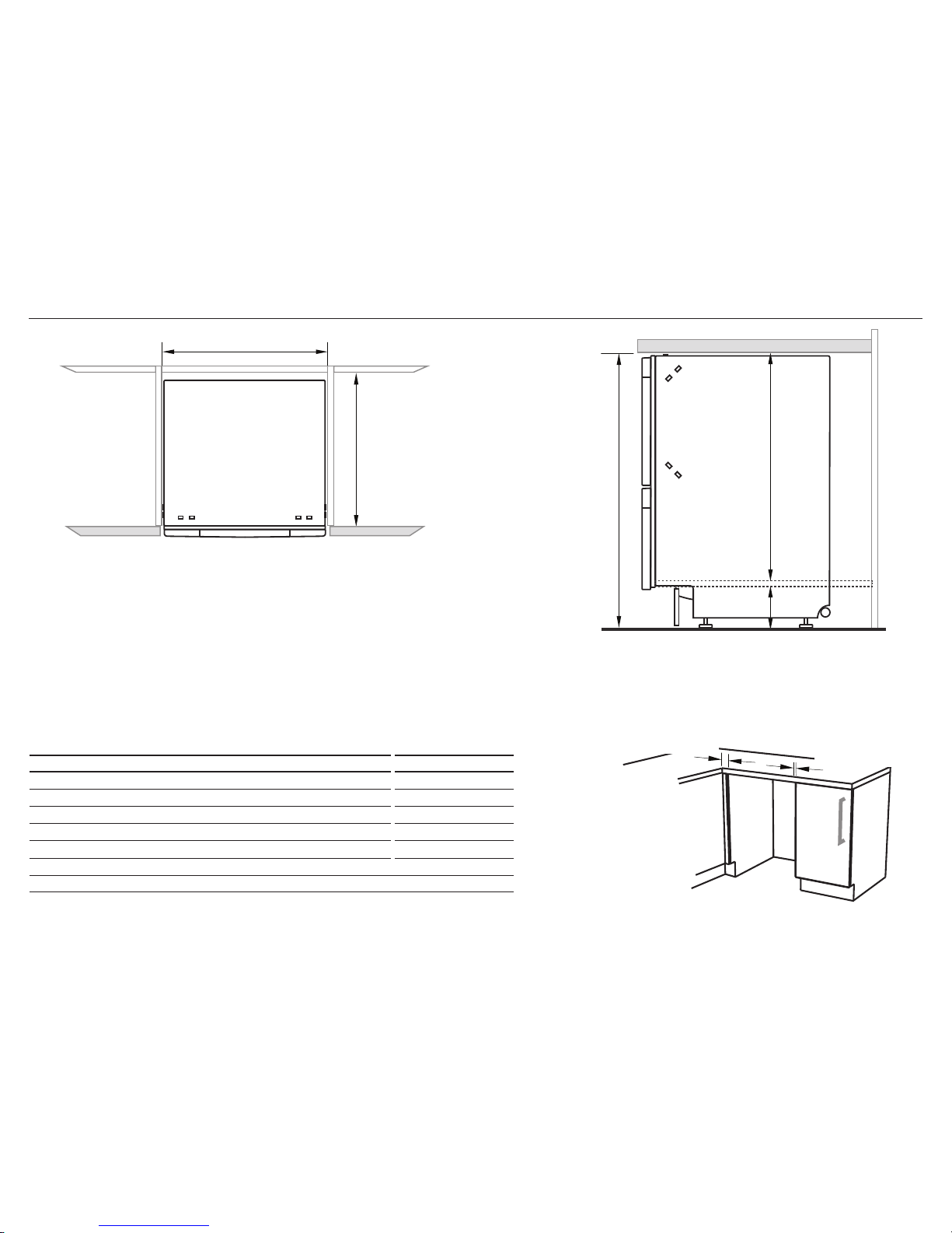
5 CABINETRY DIMENSIONS
SIDE
TOP
CABINETRY DIMENSIONS inches (mm)
N
Inside height of cavity* min. 32 5/16” (820)
O
Inside width of cavity 23 5/8” (600)
P
Inside depth of cavity min. 22 1/16” (560)
Q
Recommended height of adjacent cabinet space 30” (762)
R
Height of toekick space* 2 3/8 - 4 3/4” (60-120)
*depending on adjustment of levelling feet
D
B
E
C
H
M
L
K
N
O
P
Q
R
J
A I
G
Minimum clearances from adjacent cabinetry
min. 1/2” (13 mm)
clearance from a
corner cupboard
min. 1/16” (2 mm)
clearance to adjacent
cupboard door
8
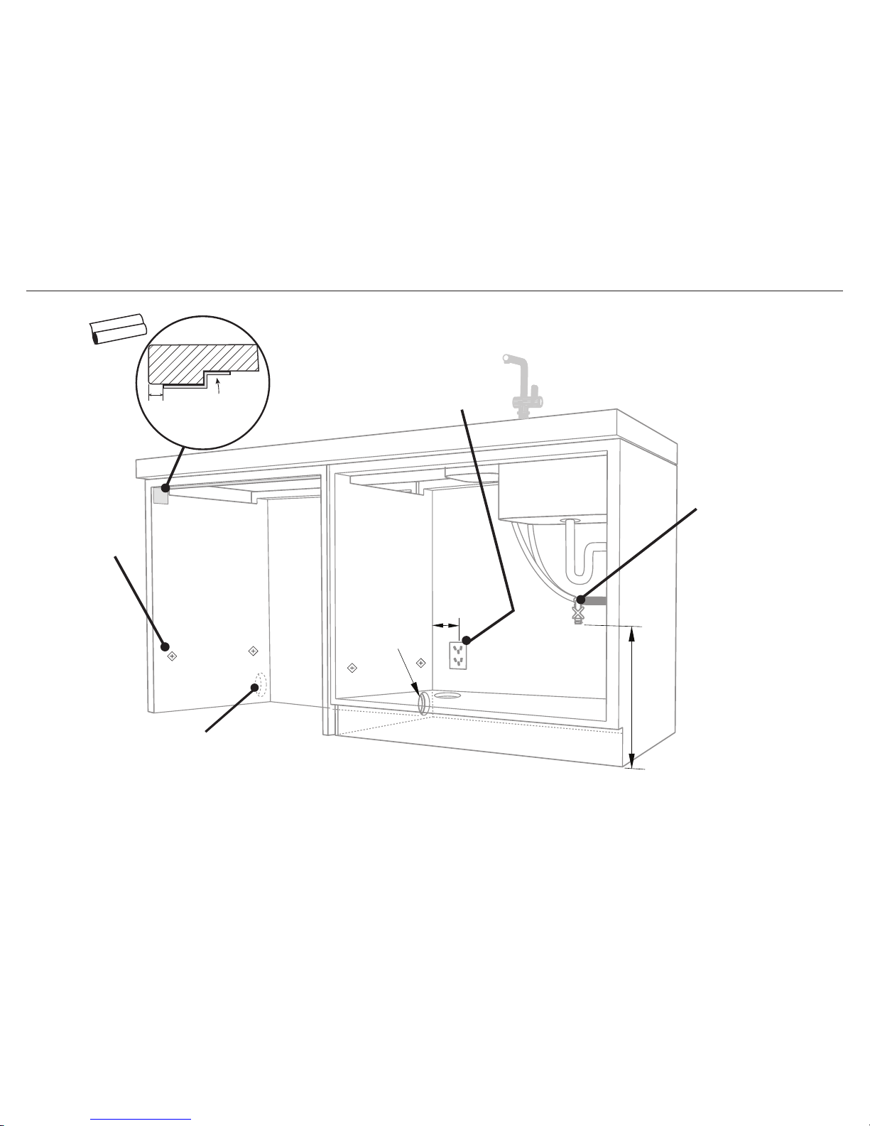
6 CAVITY PREPARATION
Water Connection
Recommended HOT
(Maximum 140°F/60°C).
Supplied hose to
suit 3⁄8” (9 mm) male
compression fitting.
Kosher requirements
Drains will need to be
separated to satisfy
kosher requirements.
We suggest you confirm
acceptability with your
local rabbi in respect to
kosher installations.
Water Pressure
Water softener models
Max. 1 MPa (145 psi)
Min. 0.1 MPa (14.5 psi)
Models without water softener
Max. 1 MPa (145 psi)
Min. 0.03 MPa (4.3 psi)
IMPORTANT!
The power outlet
must be located in a
cabinet adjacent to the
dishwasher cavity.
110-120 VAC max. 15 A
ø max. 1 1/2”
(38 mm)
max. 17 11⁄16”
(450 mm)
min. 7 7⁄8” (200 mm)
Moisture
protection
tape must
be applied.
Services hole
Can be located either side of dishwasher, preferably
at the bottom of the cavity, as shown. If adequate
clearance, services hole can be made higher to clear
toekick space. If hole is higher, ensure drain hose(s)
are routed straight into the waste connection.
If the hole is through wood, make sure its edges are
smooth and rounded.
If the hole is through metal, ensure you fit the supplied
Edge Protector to prevent damage to the power cord.
These marks indicate
formed bracket screw
locations, if securing by
drawer removal.
If there is no side
partition, you can
construct timber
bracing as something
to secure into.
3/8”
(10 mm)
COUNTERTOP
9
7 MAXIMUM DISTANCE OF HOSES & CORD FROM CHASSIS EDGE
LEFT HAND SIDE
Drain hoses - 78 1/2” (2000 mm) Drain hoses - 70 1/2” (1800 mm)
Inlet hose - 64 3/4” (1650 mm) Inlet hose - 49” (1250 mm)
Power cord (excl.plug) - 29 1/2” (750 mm) Power cord (excl.plug) - 27 1/2” (700 mm)
RIGHT HAND SIDE
10
8 RECOMMENDED METHOD (A) - SECURE WITHOUT DRAWER REMOVAL (FRAMELESS CABINETRY ONLY)
NOW CHOOSE WHICH INSTALLATION METHOD (A) OR (B)
IS MORE SUITABLE FOR YOUR CABINETRY...
(x2)
As you push product
in, pull through hoses
and cord, ensuring
they don’t get kinked
or twisted.
optionally attach the
two top mounting brackets
Initially level the product
A
A
A
B
B
Clip all four side mounting brackets
into their slots using a flat-bladed
screwdriver. Ensure they’re securely
fitted before sliding product into cavity.
The mounting slots are in pairs, one on
each side diagonally across the product. A
bracket must match A slot and B bracket
must match B slot.
B
AB
You can raise or lower
the product by twisting
the feet. Then take
care when pushing the
product into the cavity
that you do not bend the
feet.
9-A ATTACH SIDE MOUNTING BRACKETS !0-A PULL THROUGH HOSES & PUSH INTO THE CAVITY
11
!3-A FIT THE SUPPLIED TOEKICK PANEL
!1-A SECURE TO THE CABINETRY ON THE SIDES !2-A OPTIONALLY SECURE TO THE CABINETRY ABOVE
19
1
3
5
7
8
9
2
6
4
19
IMPORTANT!
Do not overtighten screw.
Where the toekick
meets the bottom
of the tub is the
cut-off point
Mark this point on the
toekick with a pencil
Lay the toekick face down on
a chopping board or similiar
Smooth the edge with a file.
Be careful of sharp edges.
Snap off the two end tabs
Slide the toekick onto
the mounting rails
either side and screw
the toekick onto the
bottom of tub on
either side.
Mounting rail
Score along the marked
cutoff line with a knife
Turn the toekick over and
score along the same line
Gently snap off the excess
2
1
3
Open the
drawer halfway.
Using a flat
bladed
screwdriver,
prise the gray
rubber plug out
of the trim
moulding.
Replace the gray
rubber plug back into
the trim moulding
and ensure the trim
seal is facing forward.
Repeat for all
four brackets.
Using a small
Philips screwdriver,
screw through the
trim moulding,
securing the side
mounting bracket
to the cabinetry.
Do not damage
the rubber
trimseal.
(x2)
The top mounting
brackets will only
bend upwards a
maximum of 3/8”
(10 mm).
12
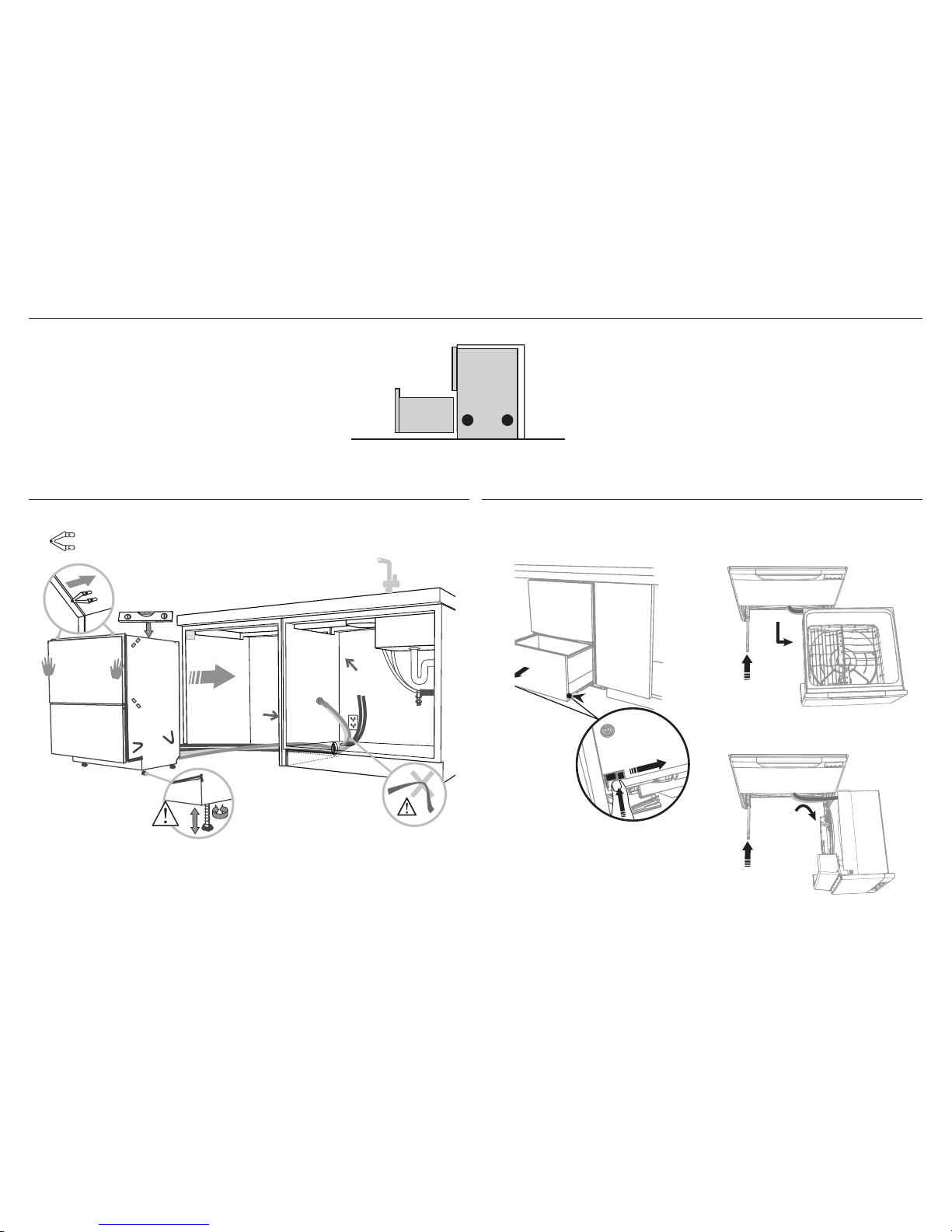
8 ALTERNATIVE METHOD (B) - SECURE BY DRAWER REMOVAL
(x2)
As you push product
in, pull through hoses
and cord, ensuring
they don’t get kinked
or twisted.
optionally attach the
two top mounting brackets
Initially level the product
You can raise or lower
the product by twisting
the feet. Then take
care when pushing the
product into the cavity
that you do not bend the
feet.
9-B PULL THROUGH HOSES & PUSH INTO THE CAVITY !0-B REMOVE THE LOWER DRAWER
1
2
4
4
3
3
4” (100 mm)
To prevent kinked hoses
Either sit the drawer down on the left
hand side (recommended) or rotate the
drawer clockwise, resting it on its side after
removal.
Press the release tabs
in on either side and
push back to release
drawer from runners.
Lift drawer off runners.
Push drawer
runners back in
on either side.
Push drawer
runners back in
on either side.
Sit the drawer down
Rotate the drawer
clockwise (max. 90
o
)
and rest on side.
 Loading...