

Fisher & Paykel CT560X Series, CT560C Series, CT5602F Series, CT2802 Series, CT6551S Series Installation Information
...
FOR CT560X, CT560C, CT5602F, CT2802, CT6551S & BICT602 SERIES COOKTOPS/HOBS
IMPORTANT INFORMATION
Please make this information available to the person
responsible for installing this cooktop as it could reduce
your installation costs.
CAUTION: In order to avoid a hazard, these appliances
must be installed according to these instructions. The
appliance is to be only installed by an authorized person.
NOTE
Ensure that there is a minimum of 60mm between the cutout and the
rear or side wall.
If the cutout is less than 100mm from the wall, some form of
protection against heat should be used, such as ceramic tiles.
The CT560X should not be installed directly above a dishwasher as
the humidity may damage the cooktop/hob electronics.
BEFORE YOU START
Do Ensure the countertop is square and level and ensure no
structural members interfere with space requirements.
Do Ensure a suitable disconnection switch is incorporated in the
permanent wiring, mounted and positioned to comply with
the local wiring rules and regulations. A means of
disconnection with at least a 3mm air gap contact separation
in all poles must be incorporated into the fixed wiring in
accordance with the wiring rules, unless the local wiring rules
allow for the following variation of these requirements: A
means of disconnection from the supply having an air gap
separation in all active (phase) conductors must be
incorporated in to the fixed wiring.
Do Use easy to clean finishes for the wall surfaces surrounding
the cooktop/hob to aid removal of any cooking fume staining
resulting from the use of the cooktop/hob.
Do Consult local building authorities and by-laws if in doubt
regarding installation.
Do Ensure that the interconnection cord between the
cooktop/hob and the oven or Control Box is not accessible via
cupboard doors after installation. This applies to any extension
cord as well, even though they are double insulated.
INSTALLATION REQUIREMENTS
If prolonged use is anticipated, or the cooktop/hob is mounted above
a drawer space, a barrier between is recommended
AND
Where the base of this product is accessible, a barrier MUST be
installed to prevent contact.
If a barrier is installed below the cooktop, this barrier must be made
of heat resistant material capable of withstanding sustained exposure
to temperatures up to 70
o
C, be at least 30mm and no greater than
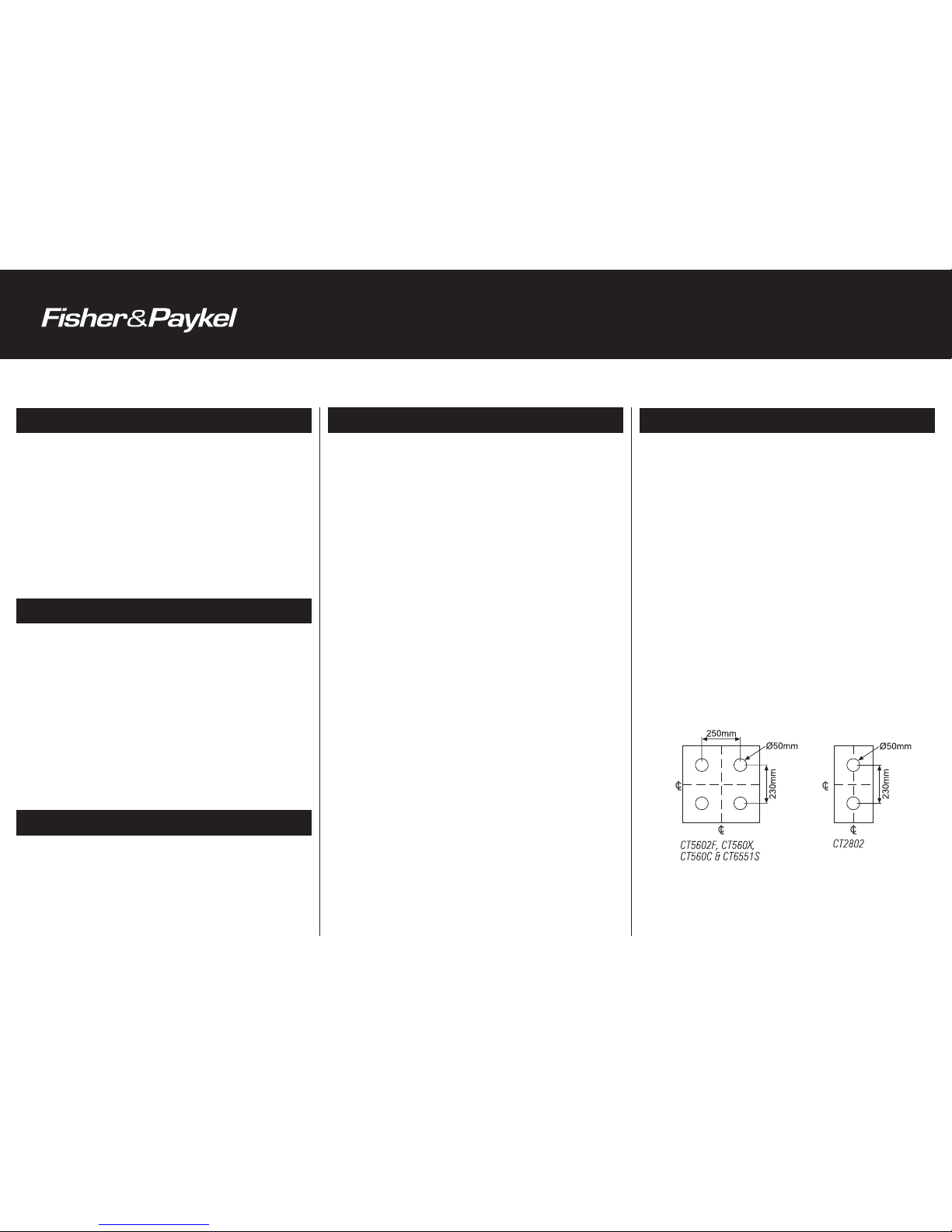
75mm below the base of the cooktop and have FOUR ventilation
holes (min 50mm - max 70mm diameter, see diagram for detail) or
TWO similar holes for the CT2802. These ventilation holes must be
open to free air. It is recommended that the barrier be removable to
allow ease of securing the cooktop with the supplied clamps.
INSTALLATION INFORMATION
Part No. 599100E 03.2006
CURRENT INFORMATION
Current Installation Instructions, Product dimensions and specifications
are available on the Fisher & Paykel web site.
www.fisherpaykel.com
CT6551S CONTROL BOX INSTALLATION
Remove the brackets from the cooktop/hob and the control box.
Place the cooktop/hob in the cutout.
Feed the cooktop/hob wiring harness up through the
control box cutout.
Remove control box cover.
Connect the cooktop wiring harness lining the numbers/letters
on the harness with the numbers/letters on the control box
connector block.
Leave plastic wiring card attached for future reference.
Clamp the wiring harness.
Wire the mains to the control box and clamp.
Replace control box cover.
Roll the control box into the cutout.
Secure control box and cooktop/hob using brackets provided.
Note: Two small brackets are provided that screw to the sides of
the control box. These must be used to clamp the control box down
to the benchtop. Three brackets are provided for clamping down the
cooktop/hob.
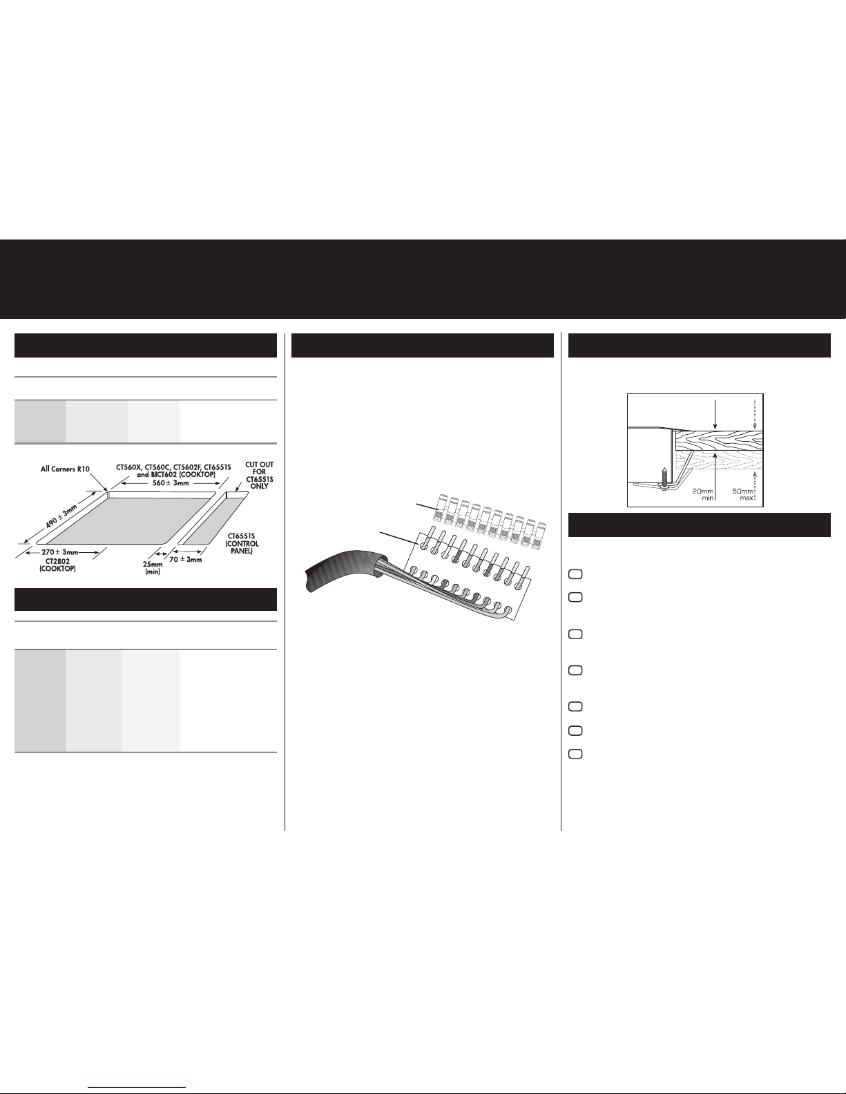
DIMENSIONS
CLAMPING DOWN COOKTOP/HOB
Place the cooktop/hob into the cutout and tighten with the supplied
clamps. These will cope with bench thickness 20-50mm.
INSTALLATION CHECKLIST
Please check through the list provided to ensure correct installation.
Is the product earthed?
Check that the power cable is NOT touching the product. This will
ensure that the cable is not damaged by heat from the product.
Is the product clamped down securely?
Operation Checklist
Check for correct function of the product by switching on all
elements and leaving on for at least 1 minute.
Are all ‘On’ lights/neons functioning?
Are all elements glowing?
To check for correct function of the ‘Surface Hot’ lights/neons,
switch off all elements. Are all ‘Surface Hot’ lights/neons
functioning?
- COOKTOP/HOB CUTOUT DIMENSIONS
Minimum Clearance (below benchtop)
CT560X 70mm CT2802 60mm
CT560C 70mm CT6551S 65mm
CT5602F 70mm BICT602 55mm
COOKTOP/HOB DIMENSIONS
Model Width Depth Height
(side to side) (front to back) (below benchtop)
CT560X 578mm 511mm 60mm
CT560C 578mm 511mm 60mm
CT5602F 578mm 511mm 60mm
CT2802 289mm 511mm 55mm
CT6551S
(Cooktop) 578mm 511mm 45mm
(Controls) 88mm 511mm 63mm
BICT602 578mm 511mm 45mm
Power Supply:
CT560X, CT560C, CT5602F, CT6551S = 5.9kW @ 220-240V (25A)
CT2802 = 3.0kW @ 220-240V (12.8A)
IMPORTANT
: When installing the CT2802, the power supply cord
must be rated for use at 1000C.
5 4 P
N E E N 3 2 1
5 4 P
N
E E N
3 2 1
control box connector block
plastic wiring card
 Loading...