

Page 1

PS-Tools
User’s Guide
for the 636 Pt Addr Panel
Page 2

Fire Alarm System Limitations
While a fire alarm system may lower insurance rates, it is not a substitute for fire
insurance!
An automatic fire alarm system—typically
made up of smoke detectors, heat detectors,
manual pull stations, audible warning devices,
and a fire alarm control panel with remote
notification capability—can provide early warning
of a developing fire. Such a system, however,
does not assure protection against property
damage or loss of life resulting from a fire.
The Manufacturer recommends that smoke
and/or heat detectors are located throughout a
protected premise following the
recommendations of the National Fire Protection
Association Standard 72 (NFPA 72),
manufacturer's recommendations, State and local
codes, and the recommendations contained in
the Guides for Proper Use of System Smoke
Detectors, which are made available at no charge
to all installing dealers. These documents can be
found at
http://www.systemsensor.com/html/applicat.html.
A study by the Federal Emergency Management
Agency (an agency of the United States
government) indicated that smoke detectors may
not go off in as many as 35% of all fires. While
fire alarm systems are designed to provide early
warning against fire, they do not guarantee
warning or protection against fire. A fire alarm
system may not provide timely or adequate
warning, or simply may not function, for a variety
of reasons:
Smoke detectors may not sense fire where
smoke cannot reach the detectors such as in
chimneys, in or behind walls, on roofs, or on the
other side of closed doors. Smoke detectors also
may not sense a fire on another level or floor of a
building. A second-floor detector, for example,
may not sense a first floor or basement fire.
Particles of combustion or “smoke” from a
developing fire may not reach the sensing
chambers of smoke detectors because:
• Barriers such as closed or partially closed
doors, walls, or chimneys may inhibit particle or
smoke flow.
• Smoke particles may become “cold,” stratify,
and not reach the ceiling or upper walls where
detectors are located.
• Smoke particles may be blown away from
detectors by air outlets.
• Smoke particles may be drawn into air returns
before reaching the detector.
The amount of “smoke” present may be
insufficient to alarm smoke detectors. Smoke
detectors are designed to alarm at various levels
of smoke density. If such density levels are not
created by a developing fire at the location of
detectors, the detectors do not go into alarm.
Smoke detectors, even when working properly,
have sensing limitations. Detectors that have
photo electronic sensing chambers tend to detect
smoldering fires better than flaming fires, which
have little visible smoke. Detectors that have
ionizing-type sensing chambers tend to detect
fast-flaming fires better than smoldering fires.
Because fires develop in different ways and are
often unpredictable in their growth, neither type of
detector is necessarily best and a given type of
detector may not provide adequate warning of a
fire. Smoke detectors cannot be expected to
provide adequate warning of fires caused by
arson, children playing with matches (especially
in bedrooms), smoking in bed, and violent
explosions (caused by escaping gas, improper
storage of flammable materials, etc.).
Heat detectors do not sense particles of
combustion and alarm only when heat on their
sensors increases at a predetermined rate or
reaches a predetermined level. Rate-of-rise heat
detectors may be subject to reduced sensitivity
over time. For this reason, the rate-of-rise feature
of each detector should be tested at least once
per year by a qualified fire protection specialist.
Heat detectors are designed to protect property,
not life.
IMPORTANT! Smoke detectors must be
installed in the same room as the control panel
and in rooms used by the system for the
connection of alarm transmission wiring,
communications, signaling, and/or power. If
detectors are not so located, a developing fire
may damage the alarm system, crippling its
ability to report a fire.
Audible warning devices such as bells may not
alert people if these devices are located on the
other side of closed or partly open doors or are
located on another floor of a building. Any
warning device may fail to alert people with a
disability or those who have recently consumed
drugs, alcohol or medication.
Please note that:
• Strobes can, under certain circumstances,
cause seizures in people with conditions such as
epilepsy.
• Studies have shown that certain people, even
when they hear a fire alarm signal, do not
respond or comprehend the meaning of the
signal. It is the property owner's responsibility to
conduct fire drills and other training exercise to
make people aware of fire alarm signals and
instruct them on the proper reaction to alarm
signals.
• In rare instances, the sounding of a warning
device can cause temporary or permanent
hearing loss.
Page 3

A fire alarm system does not operate without
any electrical power. If AC power fails, the
system operates from standby batteries only for a
specified time and only if the batteries are
properly maintained and replaced regularly.
Equipment used in the system may not be
technically compatible with the control panel. It is
essential to use only equipment listed for service
with your control panel.
Telephone lines needed to transmit alarm
signals from a premise to a central monitoring
station may be out of service or temporarily
disabled. For added protection against telephone
line failure, backup radio transmission systems
are recommended.
The most common cause of fire alarm
malfunction is inadequate maintenance. To keep
the entire fire alarm system in excellent working
order, ongoing maintenance is required per the
manufacturer's recommendations, and UL and
NFPA standards.
At a minimum, the requirements of NFPA 72 shall
be followed. Environments with large amounts of
dust, dirt or high air velocity require more
frequent maintenance. A maintenance agreement
must be arranged through the local
manufacturer's representative. Maintenance must
be scheduled monthly or as required by National
and/or local fire codes and must be performed
only by authorized professional fire alarm
installers only. Adequate written records of all
inspections must be kept.
Installation Precautions
Adherence to the following helps in problem-free installation with long-term reliability.
WARNING - Several different sources of
power can be connected to the fire alarm
control panel. Disconnect all sources of power
before servicing. Control unit and associated
equipment may be damaged by removing and/or
inserting cards, modules, or interconnecting
cables while the unit is energized. Do not attempt
to install, service, or operate this unit, until
manuals are read and understood.
CAUTION - System Reacceptance Test after
Software Changes: To ensure proper system
operation, this product must be tested in
accordance with NFPA 72 after any programming
operation or change in site-specific software.
Reacceptance testing is required after any
change, addition or deletion of system
components, or after any modification, repair or
adjustment to system hardware or wiring. All
components, circuits, system operations, or
software functions known to be affected by a
change must be 100% tested. In addition, to
ensure that other operations are not inadvertently
affected, at least 10% of initiating devices that
are not directly affected by the change, up to a
maximum of 50 devices, must also be tested and
proper system operation verified.
This system meets NFPA requirements for
operation at 0-49ºC/32-120º F and at a relative
humidity 93% ± 2% RH (non-condensing) at 32°C
± 2°C (90°F ± 3°F). However, the useful life of the
system's standby batteries and the electronic
components may be adversely affected by
extreme temperature ranges and humidity.
Therefore, it is recommended that this system
and its peripherals be installed in an environment
with a normal room temperature of 15-27º C/6080º F.
Verify that wire sizes are adequate for all
initiating and indicating device loops. Most
devices cannot tolerate more than a 10% I.R.
drop from the specified device voltage.
Like all solid state electronic devices, this
system may operate erratically or can be
damaged when subjected to the lightning induced
transients. Although no system is completely
immune from lightning transients and
interference, proper grounding reduces
susceptibility. Overhead or outside aerial wiring is
not recommended, due to an increased
susceptibility to nearby lightning strikes. Consult
with the Technical Services Department if any
problems are anticipated or encountered.
Disconnect AC power and batteries prior to
removing or inserting circuit boards. Failure to do
so can damage circuits.
Remove all electronic assemblies prior to any
drilling, filing, reaming, or punching of the
enclosure. When possible, make all cable entries
from the sides or rear. Before making
modifications, verify that they do not interfere with
battery, transformer, or printed circuit board
location.
Do not tighten screw terminals more than 9 inlbs. Over tightening may damage threads,
resulting in reduced terminal contact pressure
and difficulty with screw terminal removal.
This system contains static-sensitive
components. Always ground yourself with a
proper wrist strap before handling any circuits so
that static charges are removed from the body.
Use static suppressive packaging to protect
electronic assemblies removed from the unit.
Follow the instructions in the installation,
operating, and programming manuals. These
instructions must be followed to avoid damage to
the control panel and associated equipment.
FACP operation and reliability depend upon
proper installation.
Page 4

FCC Warning
WARNING: This equipment generates, uses, and
can radiate radio frequency energy and if not
installed and used in accordance with the
instruction manual may cause interference to
radio communications. It is tested and found to
comply with the limits for class A computing
devices pursuant to Subpart B of Part 15 of FCC
Rules, which is designed to provide reasonable
protection against such interference when
devices are operated in a commercial
environment. Operation of this equipment in a
residential area is likely to cause interference, in
which case the user must set right the required to
correct the interference at his or her own
expense.
Canadian Requirements
This digital apparatus does not exceed the Class
A limits for radiation noise emissions from digital
apparatus set out in the Radio Interference
Regulations of the Canadian Department of
Communications.
Le present appareil numerique n'emet pas de
bruits radioelectriques depassant les limites
applicables aux appareils numeriques de la
classe A prescrites dans le Reglement sur le
brouillage radioelectrique edicte par le ministere
des Communications du Canada.
Page 5

Table of Contents
1 Introduction . . . . . . . . . . . . . . . . . . . . . . . . . . . . . . . . . . . . . . . . . . . . . . . . . . . . . .1
1.1 Overview of PS-Tools . . . . . . . . . . . . . . . . . . . . . . . . . . . . . . . . . . . . . . . . . . . . . . . . 1
1.1.1 PS-Tools Features . . . . . . . . . . . . . . . . . . . . . . . . . . . . . . . . . . . . . . . . 2
1.2 User Profile . . . . . . . . . . . . . . . . . . . . . . . . . . . . . . . . . . . . . . . . . . . . . . . . . . . . . . 2
2 Setting Up PS-Tools . . . . . . . . . . . . . . . . . . . . . . . . . . . . . . . . . . . . . . . . . . . . . . . . . .3
2.1 System Requirements . . . . . . . . . . . . . . . . . . . . . . . . . . . . . . . . . . . . . . . . . . . . . . . . . 4
2.2 Complete Setup vs Custom Setup . . . . . . . . . . . . . . . . . . . . . . . . . . . . . . . . . . . . . . . . . . 4
2.3 Installing PS-Tools . . . . . . . . . . . . . . . . . . . . . . . . . . . . . . . . . . . . . . . . . . . . . . . . . . 5
2.4 Removing PS-Tools. . . . . . . . . . . . . . . . . . . . . . . . . . . . . . . . . . . . . . . . . . . . . . . . . 12
2.4.1 Removing PS-Tools using Control Panel . . . . . . . . . . . . . . . . . . . . . . . . . . . 12
3 Getting Started. . . . . . . . . . . . . . . . . . . . . . . . . . . . . . . . . . . . . . . . . . . . . . . . . . . . 13
3.1 Logging On . . . . . . . . . . . . . . . . . . . . . . . . . . . . . . . . . . . . . . . . . . . . . . . . . . . . . 14
3.2 Quitting . . . . . . . . . . . . . . . . . . . . . . . . . . . . . . . . . . . . . . . . . . . . . . . . . . . . . . . 14
4 Adding Customers. . . . . . . . . . . . . . . . . . . . . . . . . . . . . . . . . . . . . . . . . . . . . . . . . . 15
4.1 Adding a New Customer . . . . . . . . . . . . . . . . . . . . . . . . . . . . . . . . . . . . . . . . . . . . . . 17
4.1.1 Duplicating a Customer Record . . . . . . . . . . . . . . . . . . . . . . . . . . . . . . . . 18
4.2 Finding a Customer . . . . . . . . . . . . . . . . . . . . . . . . . . . . . . . . . . . . . . . . . . . . . . . . . 19
4.3 Configuring Fire Panel for a Customer . . . . . . . . . . . . . . . . . . . . . . . . . . . . . . . . . . . . . . . 19
4.4 Editing Customer Details . . . . . . . . . . . . . . . . . . . . . . . . . . . . . . . . . . . . . . . . . . . . . . 19
4.5 Deleting a Customer . . . . . . . . . . . . . . . . . . . . . . . . . . . . . . . . . . . . . . . . . . . . . . . . 20
5 Configuring Fire Panels . . . . . . . . . . . . . . . . . . . . . . . . . . . . . . . . . . . . . . . . . . . . . . . 21
5.1 Selecting Configuration Type. . . . . . . . . . . . . . . . . . . . . . . . . . . . . . . . . . . . . . . . . . . . 23
5.2 Configuring System Info . . . . . . . . . . . . . . . . . . . . . . . . . . . . . . . . . . . . . . . . . . . . . . 23
5.2.1 Communicator Settings . . . . . . . . . . . . . . . . . . . . . . . . . . . . . . . . . . . . 24
5.2.2 Central Station . . . . . . . . . . . . . . . . . . . . . . . . . . . . . . . . . . . . . . . . . 25
5.2.3 Configuring Input/Output . . . . . . . . . . . . . . . . . . . . . . . . . . . . . . . . . . . 27
5.2.4 Configuring General System Settings . . . . . . . . . . . . . . . . . . . . . . . . . . . . . 31
5.2.5 Configuring Optional Modules. . . . . . . . . . . . . . . . . . . . . . . . . . . . . . . . . 35
5.2.6 Configuring ANN BUS . . . . . . . . . . . . . . . . . . . . . . . . . . . . . . . . . . . . 36
5.3 SLC Loop Setup . . . . . . . . . . . . . . . . . . . . . . . . . . . . . . . . . . . . . . . . . . . . . . . . . . 39
5.3.1 Detectors . . . . . . . . . . . . . . . . . . . . . . . . . . . . . . . . . . . . . . . . . . . . 40
5.3.2 Modules . . . . . . . . . . . . . . . . . . . . . . . . . . . . . . . . . . . . . . . . . . . . 45
5.4 Save to Database . . . . . . . . . . . . . . . . . . . . . . . . . . . . . . . . . . . . . . . . . . . . . . . . . . 49
5.5 Save as Template . . . . . . . . . . . . . . . . . . . . . . . . . . . . . . . . . . . . . . . . . . . . . . . . . . 50
5.6 Verify Setup. . . . . . . . . . . . . . . . . . . . . . . . . . . . . . . . . . . . . . . . . . . . . . . . . . . . . 50
5.7 Simulation. . . . . . . . . . . . . . . . . . . . . . . . . . . . . . . . . . . . . . . . . . . . . . . . . . . . . . 52
5.7.1 Tabular View . . . . . . . . . . . . . . . . . . . . . . . . . . . . . . . . . . . . . . . . . . 52
5.7.2 Graphical View. . . . . . . . . . . . . . . . . . . . . . . . . . . . . . . . . . . . . . . . . 53
5.8 Changing the Download Password . . . . . . . . . . . . . . . . . . . . . . . . . . . . . . . . . . . . . . . . . 54
5.9 Upload Information . . . . . . . . . . . . . . . . . . . . . . . . . . . . . . . . . . . . . . . . . . . . . . . . . 55
5.9.1 Walktest Data. . . . . . . . . . . . . . . . . . . . . . . . . . . . . . . . . . . . . . . . . . 56
5.9.2 History Data . . . . . . . . . . . . . . . . . . . . . . . . . . . . . . . . . . . . . . . . . . 57
5.9.3 Troubleshoot Data . . . . . . . . . . . . . . . . . . . . . . . . . . . . . . . . . . . . . . . 58
5.10 Comparing Configuration. . . . . . . . . . . . . . . . . . . . . . . . . . . . . . . . . . . . . . . . . . . . . . 58
5.11 Database Backup . . . . . . . . . . . . . . . . . . . . . . . . . . . . . . . . . . . . . . . . . . . . . . . . . . 60
5.12 Database Restore . . . . . . . . . . . . . . . . . . . . . . . . . . . . . . . . . . . . . . . . . . . . . . . . . . 61
5.13 Database Migration . . . . . . . . . . . . . . . . . . . . . . . . . . . . . . . . . . . . . . . . . . . . . . . . . 62
5.14 Connecting to the Database . . . . . . . . . . . . . . . . . . . . . . . . . . . . . . . . . . . . . . . . . . . . . 63
5.15 Viewing Migration Information . . . . . . . . . . . . . . . . . . . . . . . . . . . . . . . . . . . . . . . . . . 64
5.16 Viewing Last Configuration Date. . . . . . . . . . . . . . . . . . . . . . . . . . . . . . . . . . . . . . . . . . 65
5.17 Modifying Customer Details . . . . . . . . . . . . . . . . . . . . . . . . . . . . . . . . . . . . . . . . . . . . 66
5.18 Importing Configuration . . . . . . . . . . . . . . . . . . . . . . . . . . . . . . . . . . . . . . . . . . . . . . 67
5.19 Importing all Configurations . . . . . . . . . . . . . . . . . . . . . . . . . . . . . . . . . . . . . . . . . . . . 68
5.20 Exporting Configuration . . . . . . . . . . . . . . . . . . . . . . . . . . . . . . . . . . . . . . . . . . . . . . 69
Page 6

5.21 Deleting Template . . . . . . . . . . . . . . . . . . . . . . . . . . . . . . . . . . . . . . . . . . . . . . . . . . 70
6 Upload/Download Configuration Data . . . . . . . . . . . . . . . . . . . . . . . . . . . . . . . . . . . . . .71
6.1 Connection Settings . . . . . . . . . . . . . . . . . . . . . . . . . . . . . . . . . . . . . . . . . . . . . . . . . 72
6.1.1 USB Device Settings . . . . . . . . . . . . . . . . . . . . . . . . . . . . . . . . . . . . . . 72
6.1.2 Modem Settings . . . . . . . . . . . . . . . . . . . . . . . . . . . . . . . . . . . . . . . . . 73
6.1.3 Serial Port Settings . . . . . . . . . . . . . . . . . . . . . . . . . . . . . . . . . . . . . . . 74
6.2 Connect/Disconnect to Fire Panel . . . . . . . . . . . . . . . . . . . . . . . . . . . . . . . . . . . . . . . . . . 75
6.3 Download Configuration Data to Fire Panel . . . . . . . . . . . . . . . . . . . . . . . . . . . . . . . . . . . . 77
6.4 Upload Configuration Information from Fire Panel. . . . . . . . . . . . . . . . . . . . . . . . . . . . . . . . . 81
7 Generating Report . . . . . . . . . . . . . . . . . . . . . . . . . . . . . . . . . . . . . . . . . . . . . . . . .87
8 Troubleshooting . . . . . . . . . . . . . . . . . . . . . . . . . . . . . . . . . . . . . . . . . . . . . . . . . .89
8.1 Panel Connection Busy . . . . . . . . . . . . . . . . . . . . . . . . . . . . . . . . . . . . . . . . . . . . . . . 89
8.2 Panel Connection Lost. . . . . . . . . . . . . . . . . . . . . . . . . . . . . . . . . . . . . . . . . . . . . . . . 90
8.3 PS-Tools Failed to Download Data to Panel . . . . . . . . . . . . . . . . . . . . . . . . . . . . . . . . . . . . 91
8.4 PS-Tools Failed to Upload Data from Panel . . . . . . . . . . . . . . . . . . . . . . . . . . . . . . . . . . . . 92
8.5 Request Denied for Verify Secret Code . . . . . . . . . . . . . . . . . . . . . . . . . . . . . . . . . . . . . . . 93
8.6 Ring Count Error . . . . . . . . . . . . . . . . . . . . . . . . . . . . . . . . . . . . . . . . . . . . . . . . . . 94
8.7 Other Fire Alarm System Events . . . . . . . . . . . . . . . . . . . . . . . . . . . . . . . . . . . . . . . . . . 95
A Appendix . . . . . . . . . . . . . . . . . . . . . . . . . . . . . . . . . . . . . . . . . . . . . . . . . . . . . . 97
A.1 Coding Selection. . . . . . . . . . . . . . . . . . . . . . . . . . . . . . . . . . . . . . . . . . . . . . . . . . . 97
A.2 Two Stage Operation . . . . . . . . . . . . . . . . . . . . . . . . . . . . . . . . . . . . . . . . . . . . . . . . 97
A.3 Synchronized NAC Operation. . . . . . . . . . . . . . . . . . . . . . . . . . . . . . . . . . . . . . . . . . . . 98
Page 7

About This Guide
This guide describes the procedures for installing PS-Tools and using PS-Tools for configuring and
monitoring the 636 Pt Addr.Fire Alarm Control Panel (FACP).
Overview of Contents
PS-Tools User Guide
Audience
This document contains the following chapters and appendix.
• Chapter 1, Introduction, introduces PS-Tools application and describes its features.
• Chapter 2, Setting Up PS-Tools, provides the steps for installing PS-Tools.
• Chapter 3, Getting Started, provides the steps for logging onto PS-Tools.
• Chapter 4, Adding Customers, describes the steps for adding and maintaining the details of the
customers for the fire panel.
• Chapter 5, Configuring Fire Panels, details the steps to configure the fire panel for a customer.
• Chapter 6, Upload/Download Configuration Data, presents the technique to download
configuration data to the fire panel and upload configuration data from the fire panel.
• Chapter 7,Generating Report, depicts the process to generate the Configuration Data report.
• Chapter 8, Troubleshooting, lists the events and faults that can occur in the fire panel.
• Appendix, gives additional information about the coding selections, two stage operation, and
synchronized NAC operation.
This guide is intended for the installers and operators of PS-Tools, who ar e trained in configuring and
monitoring the fire panel.
Assumed Knowledge
It is assumed that you are familiar with the Microsoft Windows user in terface, configuring and
monitoring the 636 Pt Addr. fire panel.
636 Pt Addr.Panel
PS-Tools 04/2010 iii
Page 8

Related Documents
For more information about topics that are rel evant to the subject of this manua l, refer to the following
document.
Document Title Contents
636 Pt Addr. (Document Id:
51335)
Typographical Conventions
This document uses the following typographical conventions.
Style What it represents Example
Bold Menu titles, user interface
literals
Buttons you click to perform
actions
Italic
Items you select 2-Wire Detector
Cross-reference within
document
Cross-reference to chapters See Getting Started.
Installation procedures and
technical specifications for the
Fire Alarm Control Panel.
Double-click PS-Tools
icon.
Click Exit to close the
program.
For more information,
see Configuring Fire
Panel.
iv 636 Pt Addr.Panel
PS-Tools 04/2010
Page 9

1
1 Introduction
This chapter provides an overview of the PS-Tools (Programming Software Tools) application and
describes the profiles of the users.
Overview of PS-Tools
PS-Tools is a convenient and powerful tool which can be used for configuring the programming
data for the 636 Pt Addr. Fire Alarm Control Panel (FACP) from a computer or a laptop.
You can configure the fire alarm system in three ways.
1. Using PS-Tools
2. Using the fire panel keypad
3. Using PS2 Style Keyboard
Configuring through Fire Panel Keypad
Configuring through panel keypad involves making changes in several screens for a single control
using the panel keypad. This way of configuration is tedious.
Configuring through PS-Tools
You can configure the fire panel using PS-Tools, instead of using a panel keypad. This way is more
efficient because of the user-friendly screens in PS-Tools.
Configuring through PS2 Style Keyboard
You can configure the 636 Pt Addr. fire panel by connecting a PS2 Style Keyboard, instead of using
the panel keyboard.
636 Pt Addr.Panel
PS-Tools 04/2010 1
Page 10

Introduction
PS-Tools Features
PS-Tools provides many features such as:
• Maintaining details of the fire panel customers.
• Configuring the settings for the fire panel for a customer.
• Verify Setup feature which helps in verifying the configuration before downloading to panel.
• Download utility to download the configuration information to the fire panel.
• Upload utility to upload the event logs, history data, and troubleshoot data from fire panel.
• File Comparison utility, which allows location by location comparison of separate upload and
download files.
• Export Configuration feature to export the saved configuration to a file.
• Import Configuration details from the panel.
• Graphical representation of the installed devices.
• Simulation feature, which displays the correlation of the input and output devices.
• Migrate the database files from PK-Plus to PS-Tools.
• Fire panel troubles and events troubleshooting.
User Profile
Table 1-1 lists the roles and responsibilities for the PS-Tools users.
Table 1-1 User roles and responsibilities
User Role Responsible for
Service Technician/Installer • Commissioning and installing the fire
Support Engineer • Attending the support calls from the
Fire Panel distributors • Marketing the fire panels.
Primary and Secondary Central
Stations
alarm system.
• Configuring the fire panel
programmable data.
fields.
• Providing training to the service
technicians.
• Reporting events, troubles, and alarms
to the central station.
2 636 Pt Addr.Panel
PS-Tools 04/2010
Page 11

2
2 Setting Up PS-Tools
This chapter describes the procedures for installing and removing the PS-Tools.
The following table describes the tasks you can perform using different sections of this chapter.
Section Description Refer to
System Requirements Lists the hardware and software
Complete Setup vs Custom Setup
Installing
Removing
PS-Tools
PS-Tools
requirements to install the
application.
Helps you to become familiar with the
deployment scenario for
Provides guidelines for installing the
PS-Tools in your computer.
Outlines procedures for removing
PS-Tools from your computer.
PS-Tools
PS-Tools.
page 4
page 4
page 5
page 12
636 Pt Addr.Panel
PS-Tools 04/2010 3
Page 12

Setting Up PS-Tools
System Requirements
Before you begin the setup process, ensure that your laptop or computer has the necessary hardware,
software, and support components.
Component Requirement
Operating System Windows 2000 Professional Service Pack 4 or
Processor GHZ P4 processor
RAM Minimum 256 MB
Cache 512 K
Hard Disk Drive 20 GB with a minimum of 1 GB of available space
Graphic Board and Monitor 1024 x 768 pixel or higher resolution
Windows XP or Windows 2003 Server Standard
Service Pack 2 or Windows Vista or Windows 7
Color Palette 256 colors, True Color, Font size: small or big.
Communication Serial Port
Disk Drive A CD-ROM Drive
Printer HP LaserJet
Complete Setup vs Custom Setup
PS-Tools setup offers the following installation options.
• Complete Setup (default) installs both the PS-Tools Client and Server. The Complete setup is
used in a stand-alone scenario, where the PS-Tools Client and Server is installed on the same
computer.
• Custom Setup can be used for installing either the PS-Tools Client or the PS-Tools Server.
The Custom setup is typically used in a network scenario, where the PS-Tools Server
(database) is installed at a central location.
4 636 Pt Addr.Panel
PS-Tools 04/2010
Page 13
Installing PS-Tools
To install PS-Tools
1. Insert the CD into the CD- R OM drive and go to the PS-Tools folder.
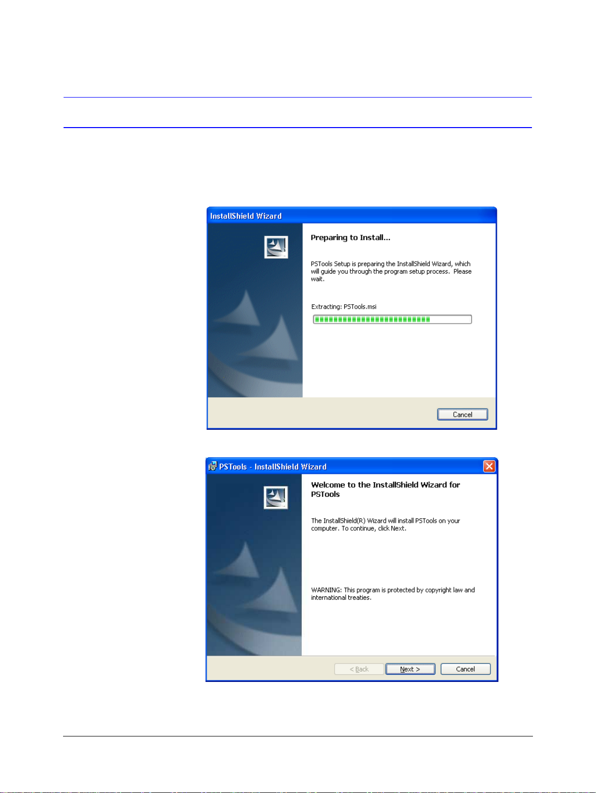
2. Double-click the PS-Tools Setup.exe. The PS-Tools - InstallShield Wizard dialog box
PS-Tools User Guide
appears.
3. Click Next. The Destination Folder dialog box appears.
636 Pt Addr.Panel
PS-Tools 04/2010 5
Page 14
Setting Up PS-Tools
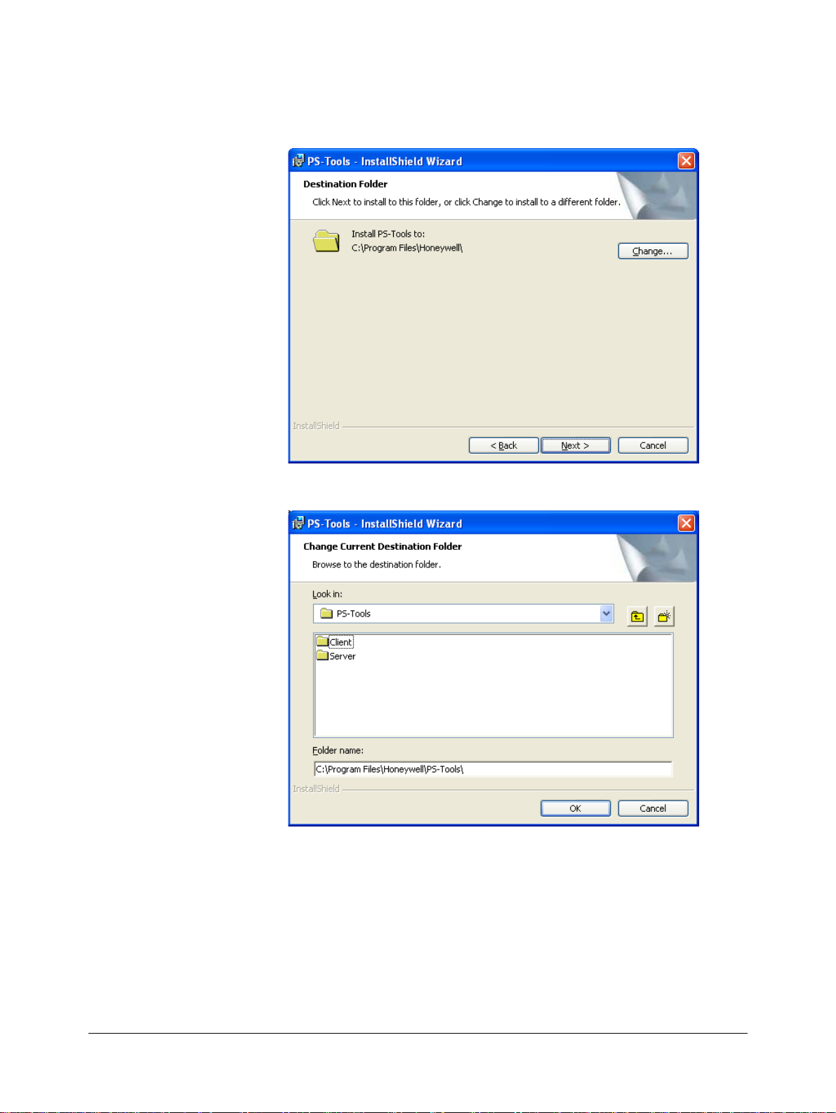
4. Click Change to change the destinati on folder.
The Change Current Destination Folder dialog box appears.
By default, the destination folder is C:\Program Files\Honeywell\PS-Tools.
5. Locate the folder where you want to install PS-Tools, and Click OK.
6. Click Next to continue with the installation.
6 636 Pt Addr.Panel
PS-Tools 04/2010
Page 15
Note
• If there is no database of a previously installed PS-Tool, the Create new
download password dialog box appears.
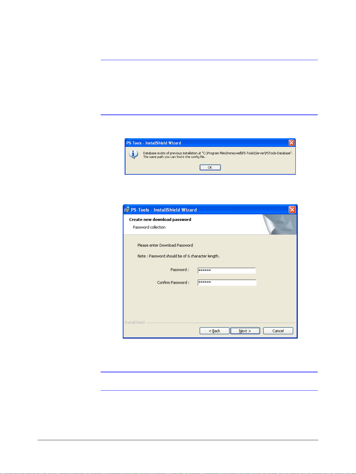
• If the database of a previously installed PS-Tools exists, a message indicating the
folder path of the database appears.
7. Click OK to continue.
PS-Tools User Guide
The Create new download password dialog box appears.
8. Type the download password in Password and then type the password again in Confirm
Password box.
Note Ensure that the password is six characters long.
636 Pt Addr.Panel
PS-Tools 04/2010 7
Page 16
Setting Up PS-Tools
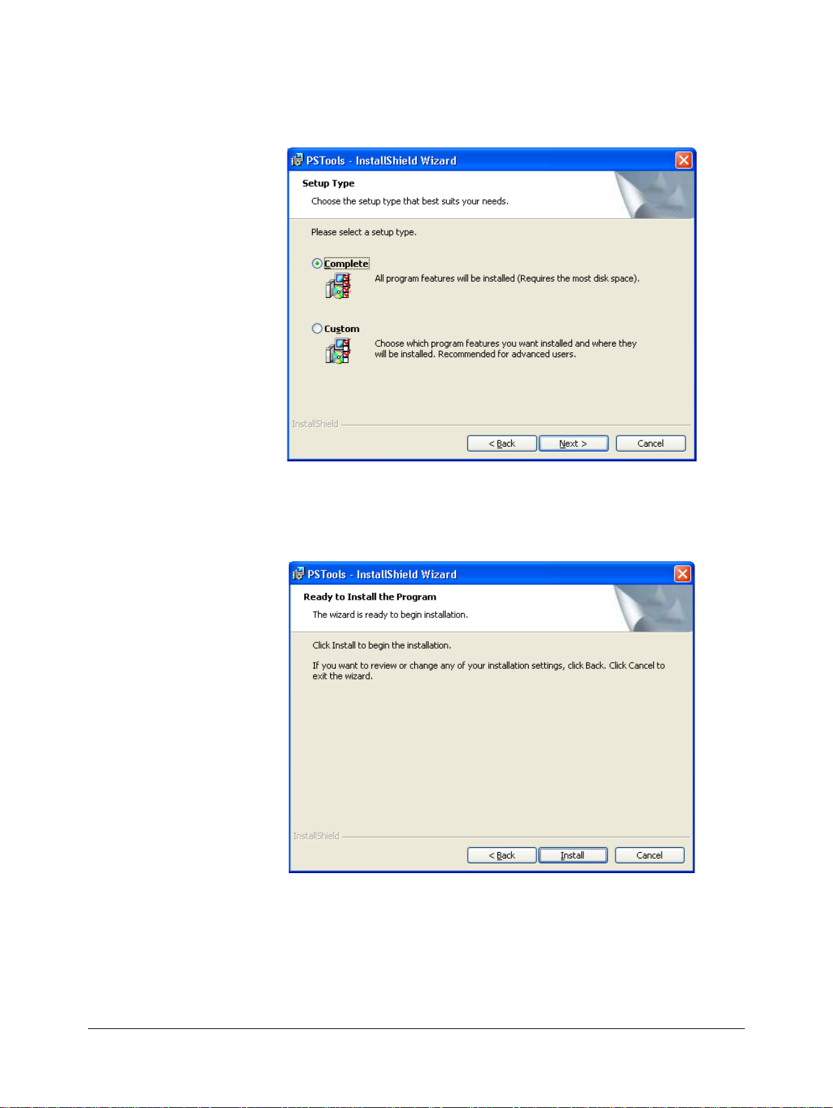
9. Click Next. The Setup Type dialog box appears.
For Complete Setup
10. Select Complete to install both the PS-Tools Client and Server.
11. Click Next. The Ready to Install dialog box appears.
8 636 Pt Addr.Panel
PS-Tools 04/2010
Page 17
PS-Tools User Guide
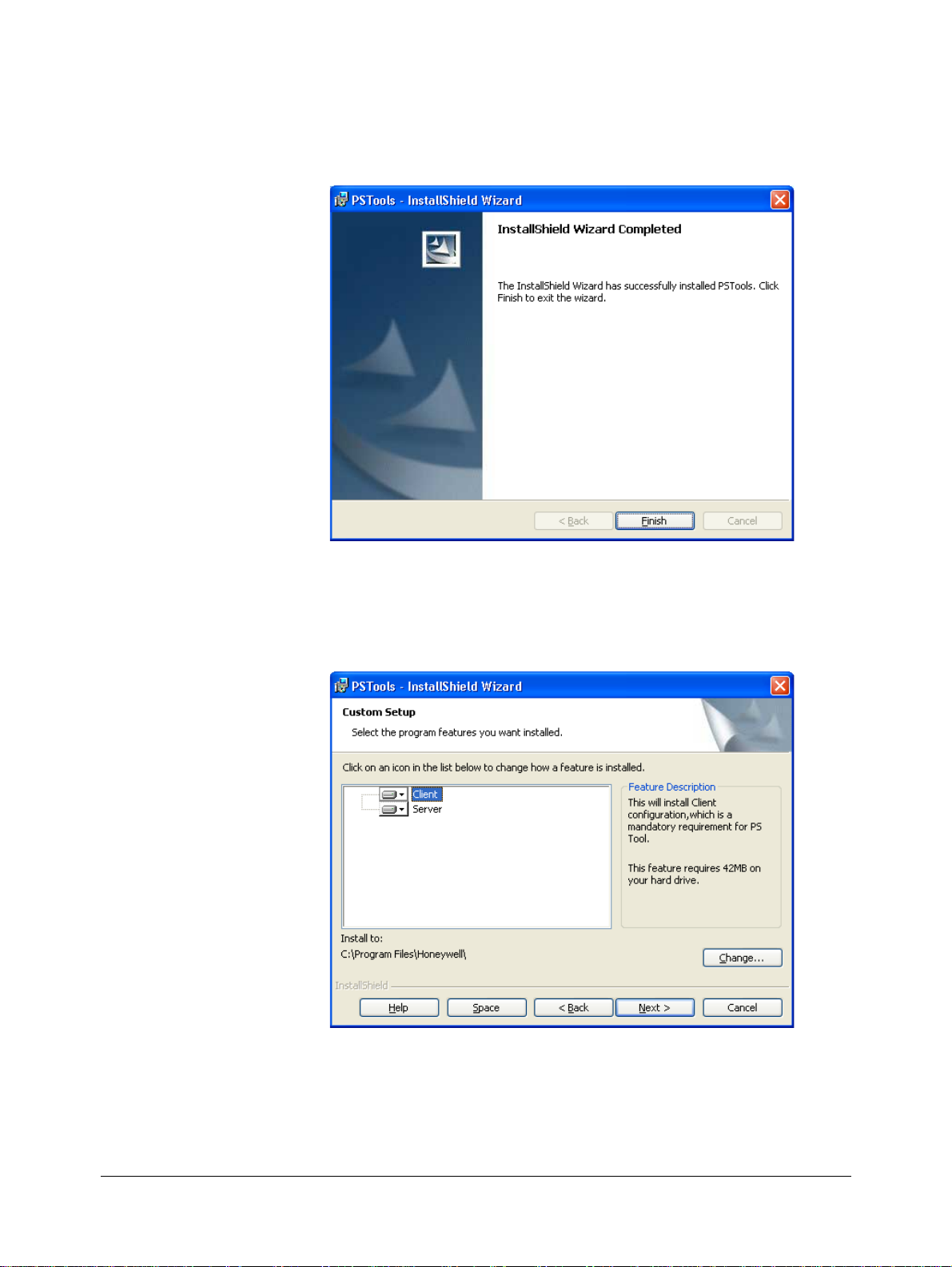
12. Click Install. A progress indicator appears, indicating the progress of installation to install the
PS-Tools.
13. Click Finish. The PS-Tools is installed on your computer.
For Custom Setup
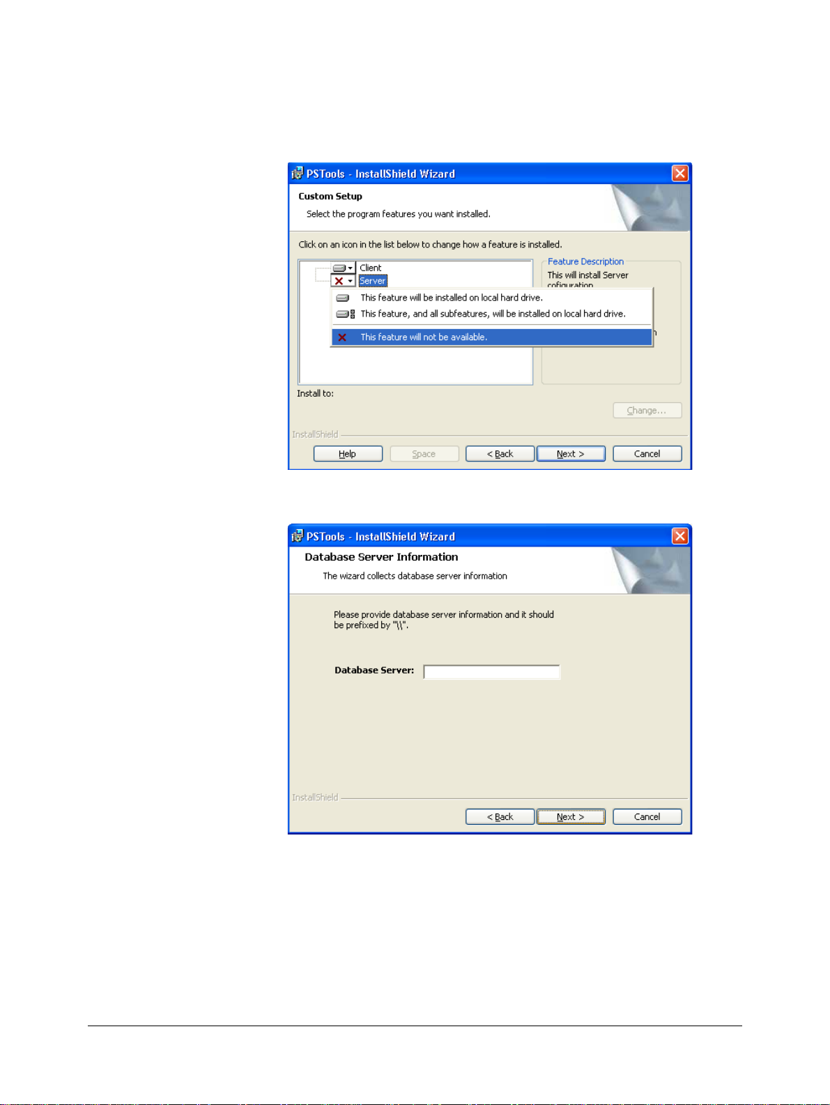
14. In the Setup Type dialog box, select Custom setup to install only the PS-Tools Client.
15. Click Next. The Custom Setup dialog box appears.
636 Pt Addr.Panel
PS-Tools 04/2010 9
Page 18
Setting Up PS-Tools
16. In the Custom Setup dialog box, select the option in the Server list to disable the PS-Tools
Server, to install only the PS-Tools Client.
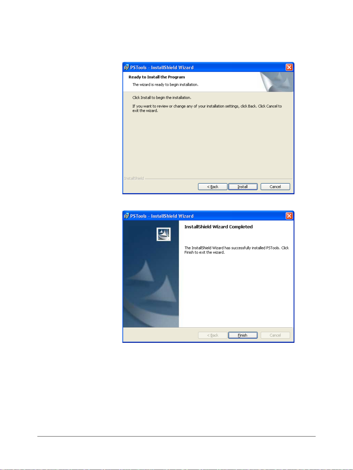
17. Click Next. The Database Server Information dialog box appears, if you have selected the
Client setup.
18. Type the IP address of the PS-Tools Server in Database Server.
19. Click Next. The Ready to Install dialog box appears.
10 636 Pt Addr.Panel
PS-Tools 04/2010
Page 19
PS-Tools User Guide
20. Click Install. A progress indicator appears, indicating the progress of installation.
21. Click Finish. The PS-Tools is installed on your computer.
636 Pt Addr.Panel
PS-Tools 04/2010 11
Page 20

Setting Up PS-Tools
Removing PS-Tools
PS-Tools can be removed using the Control Panel.
Removing PS-Tools using Control Panel
1. Click Start, and then choose Settings > Control Panel. The Control Panel window appears.
2. Double-click Add or Remove Programs.
3. In the Add or Remove Programs window, select PS-Tools in the Currently installed
programs list.
4. Click Remove. A message asking for your confirmation appears.
5. Click Yes. The PS-Tools application is removed from your computer.
12 636 Pt Addr.Panel
PS-Tools 04/2010
Page 21

3
3Getting Started
This chapter describes how to log on to and quit the PS-Tools.
The following table describes the tasks you can perform using different sections of this chapter.
Section Description Refer to
Logging On Log on to PS-Tools page 14
Quitting Exit PS-Tools. page 14
636 Pt Addr.Panel
PS-Tools 04/2010 13
Page 22
Getting Started
Logging On
To log on to PS-Tools
1. Click Start, and then choose Programs > PS-Tools > PS-Tools
or
Double click the PS-Tools icon on the desktop. The initial customer details window appears.
2. On this window, you can add the details of the customers for the fire panel. For more
information on adding customers, see
Adding Customers.
Quitting
To quit the PS-Tools application, click in the upper-right corner of the window
or
Click Exit in the File menu.
14 636 Pt Addr.Panel
PS-Tools 04/2010
Page 23
4
4 Adding Customers
Using PS-Tools, you can configure the settings of the 636 Pt Addr. Fire Alarm Control Panel
(FACP) and in addition, maintain the details of the fire panel customers.
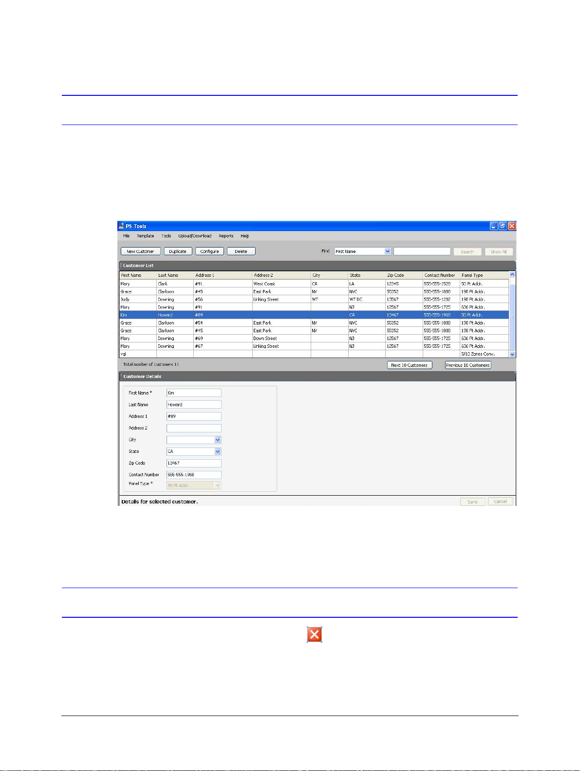
Before you configure the fire panel settings, you need to add the customer information to the
PS-Tools database. The customer details such as First Name, Last Name, Address 1, Address 2,
City, State, ZipCode, Contact Number, and Panel Type (panel version) must be added.
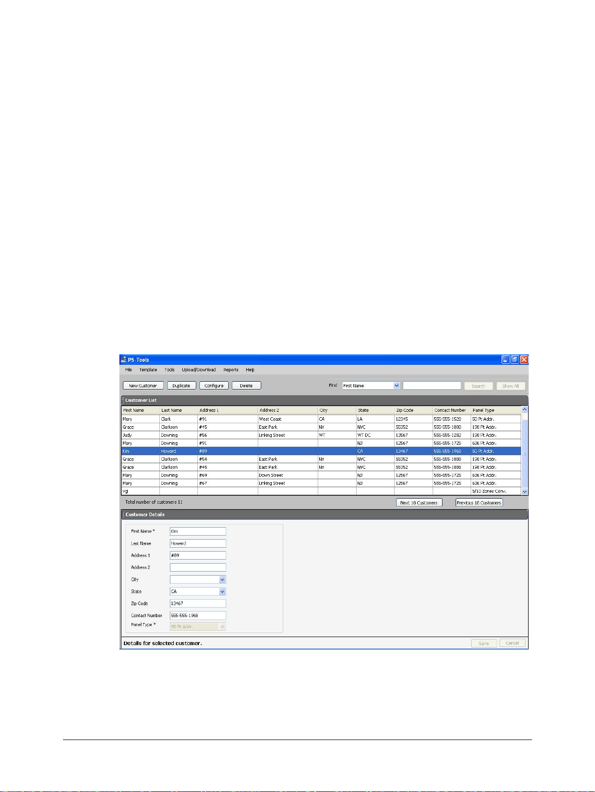
When you log on to the PS-Tools, the customer details window appears. This window consists of
the Customer List and the Customer Details sections. The Customer List section displays the list
of existing customers for the fire panel and the Customer Details section displays the details of a
selected customer.
636 Pt Addr.Panel
PS-Tools 04/2010 15
Page 24

Adding Customers
The customer details window in the PS-Tools helps you to:
• Add a new customer.
• Find an existing customer.
• Configure the fire panel for a customer.
• Delete a customer record.
16 636 Pt Addr.Panel
PS-Tools 04/2010
Page 25
Adding a New Customer
A new customer can be the protection services staff for campuses such as museums, universities, or
schools, where the 636 Pt Addr. Fire Alarm Control System is installed. Details such as First Name,
Last Name, Address 1, and so on can be added for each customer of the fire panel.
To enter the new customer details
1. Click New Customer.
2. Type the First Name, Last Name, Address 1, Address 2, City, State, ZipCode, and Contact
Number for the customer. The First Name and the Panel Type information are mandatory.
3. Select the 636 Pt Addr. fire panel version.
4. Click Save. A message asking for confirmation appears.
Note Fields marked with * are mandatory.
PS-Tools User Guide
5. Click Yes. The details for the new customer are added in PS-Tools.
636 Pt Addr. Panel
PS-Tools 04/2010 17
Page 26
Adding Customers
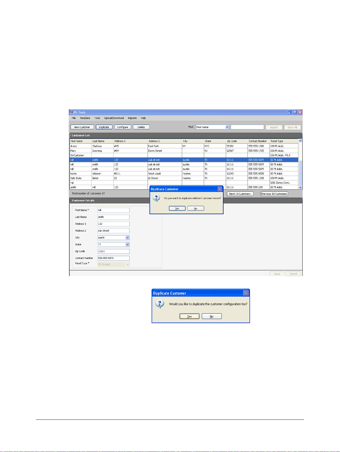
Duplicating a Customer Record
You can also add a new customer in PS-Tools by making a copy of an existing customer record and
modifying the information.
To duplicate the customer record
1. Select the customer record and click Duplicate. A message asking for confirmation appears.
2. Click Yes in the confirmation message to proceed.
3. To duplicate the configuration information along with the customer record, click Yes in the
Duplicate Customer dialog box. To duplicate only the customer record, click No.
18 636 Pt Addr.Panel
PS-Tools 04/2010
Page 27

Finding a Customer
Using the Find option, you can find the details of a customer. You can search by the First Name, Last
Name, Address 1, Address 2, City, State, ZipCode, Contact Number, or the Panel Type. The Search
results are displayed in the Customer List section.
To find a customer
1. From the Find list, select the search option.
2. In the text box provided alongside, type the keyword for the search.
3. Click Search. The search results are displayed in the Customer List.
To retrieve all customer records, click Show All. All the customer records appears in the Customer
List.
PS-Tools User Guide
Configuring Fire Panel for a Customer
Using the Configure option, you can configure all the fire alarm system settings. Before you
configure the fire panel, ensure you add the new customer details to the PS-Tools database.
To configure the fire panel for a customer
1. Using the Find option, select the customer record.
2. Click Configure.
For more information about configuring the fire panels, see Configuring Fire Panels.
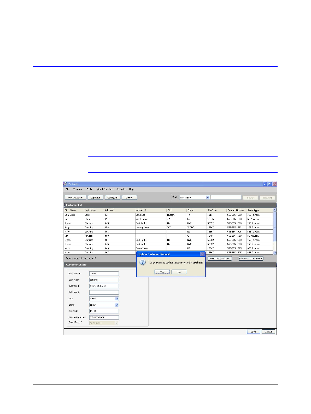
Editing Customer Details
You can update all the customer details using the PS-Tools.
To edit the customer details
1. Using the Find option, select the customer record you want to edit.
2. Update the customer data in the Customer Details section.
3. Click Save. If you select another customer record without saving, you are prompted to save the
updated record.
4. Click Yes to update the customer details in PS-Tools.
636 Pt Addr. Panel
PS-Tools 04/2010 19
Page 28
Adding Customers
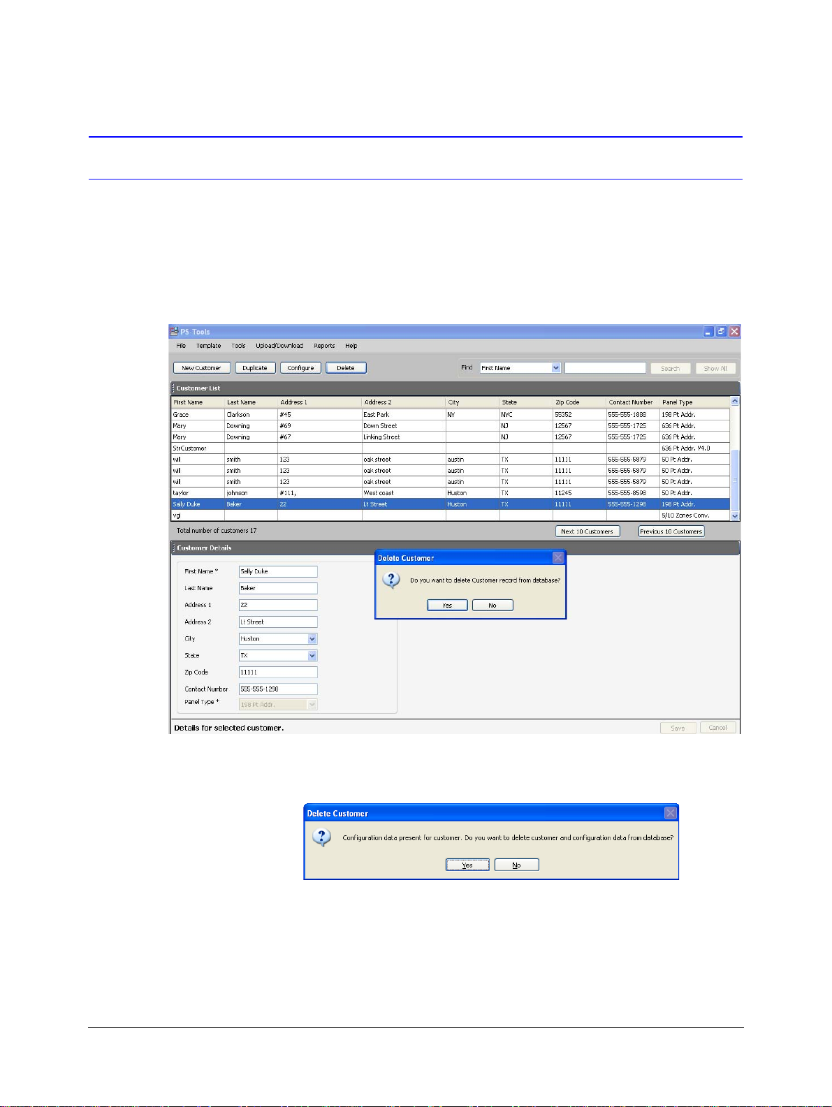
Deleting a Customer
When a customer account is considered inactive, you can delete the customer record. The saved
configuration information for the fire panel also gets deleted.
To delete a customer record
1. Using the Find option, select the customer record you want to delete.
2. Click Delete. A message asking for confirmation appears.
3. Click Yes to delete the customer record. If configuration settings exist for the customer record,
a message, asking for confirmation to delete the configuration information, is displayed. The
following screen appears:
4. To delete the customer record along with the configuration information, click Yes.
20 636 Pt Addr.Panel
PS-Tools 04/2010
Page 29

5
5 Configuring Fire Panels
Using PS-Tools, you can configure the fire panel settings. Configuring a fire panel involves:
• Configuring the settings for input and output modules.
• Configuring the fire panel settings such as date and time, banner display, fire panel
passwords, and other panel settings.
• Configuring the SLC loop setup for the detectors and modules.
• Verifying the SLC loop setup.
• Simulating the setup to evaluate SLC loop.
• Modifying the customer details in the server.
• Migrating the configuration information from PK-Plus to PS-Tools database.
After you configure the fire panel settings, connect the computer to the fire panel and download the
configuration settings. In addition, you can upload the configuration information from the fire
panel, and view the fire alarm system settings in PS-Tools.
The following table describes the tasks you can perform using different sections of this chapter.
Section Description Refer to
Selecting Configuration Type
Configuring System
Info
SLC Loop Setup To add detectors and modules to the SLC
Save to Database To save the configuration in the PS-Tools
Save as Template To save the configuration as a template page 50
Verify Setup To verify the SLC loop setup page 50
Simulation To view the zone correlations for the installed
Upload Information To view the uploaded information from the
Comparing Configuration
Database Backup To save the database backup page 60
Database Restore To restore the database.
To select a configuration type in PS-Tools page 23
To configure the
input/output modules, optional modules
and the general system settings
loop
database
devices to confirm the programming
636 Pt Addr. panel
To compare the configuration for two different customers
communicator settings,
page 23
page 31
page 49
page 52
page 55
page 58
page 61
636 Pt Addr.Panel
PS-Tools 04/2010 21
Page 30

Configuring Fire Panels
Section Description Refer to
Database Migration To migrate the information from
PK-Plus to PS-Tools database.
Connecting to the
Database
Viewing Migration
To connect to the database client or
server
To view information on migration.
Information
Viewing Last Con-
To view the configuration date page 65
figuration Date
Modifying Cus-
tomer Details
Importing Configu-
To modify the customer details in the
server.
To import a saved configuration
ration
Importing all Con-
To import all the saved configuration page 68
figuration
Exporting Configuration
Deleting Template To delete a configuration template not opera-
To export a saved configuration page 69
tional
page 62
page 63
page 64
page 66
page 67
page 70
22 636 Pt Addr.Panel
PS-Tools 04/2010
Page 31

Selecting Configuration Type
To select a configuration type
1. Using the Find option in the initial screen, select a customer record. For more information, see
Finding a Customer.
2. Click Configure to program the fire panel settings. The Configuration Type dialog box
appears.
PS-Tools User Guide
3. In the Select Configuration list, perform one of the following:
• Select the default option Factory Default, if you are configuring for the first time.
or
• Select a previously saved configuration which appears in the list.
4. Click OK. The System Info -> Communicator Settings -> Central Station pane appears (see
Figure 5-1).
Configuring System Info
In PS-Tools, configuring the system information involves the following steps.
1. Configuring the communicator settings (see Communicator Settings)
a. Central Station (see Central Station)
b. Primary Central Station (see Primary Central Station)
c. Secondary Central Station (see Secondary Central Station)
2. Configuring the input/output modules (see Configuring Input/Output
a. Relays (see Relay)
b. Zones (see Zones)
c. Special Zones (see Special Zones)
d. NACs (NAC 1, NAC 2, NAC 3, and NAC 4) (see NAC (Notification Appliance Circuits))
3. Configuring the general system settings which include the timers, clock format, trouble
reminder, and other settings (see Configuring General System Settings)
4. Configuring the Optional Modules (see Configuring Optional Modules)
636 Pt Addr. Panel
PS-Tools 04/2010 23
Page 32

Configuring Fire Panels
5. SLC Loop Setup (see SLC Loop Setup)
a. Detectors (see Detectors)
b. Modules (see Modules)
Communicator Settings
The Digital Alarm Communicator/Transmitter (DACT) module is used to transmit system status to
central station receivers through the public switched telephone network. All circuitry and connectors
are contained on a compact module, which is located near the lower - center of the main circuit board.
In PS-Tools, you must enable the reporting from the communicator, to report the fire alarm system
status, alarm, and trouble conditions to the central station through the public switched telephone
network. The System Info -> Communicator Settings ->Central Station pane appears after you
select the configuration type.
Figure 5-1 Configure Communicator Settings
To configure the communicator
1. Click Communicator Enabled, to enable the reporting from the communicator.
2. Type the Panel Id which is a four digit code used by the Service Terminal to identify the fire
panel. The factory default value is 0000. The valid entries are 0-9 and A-F.
You must program the four digit panel id, the first time you download the configuration to fire
panel.
3. Type the No. of Rings to Answer, which is the number of rings after which a call is answered
by the panel.
24 636 Pt Addr.Panel
PS-Tools 04/2010
Page 33

Central Station
PS-Tools User Guide
4. Type the addresses for Service Terminal1 and Service Terminal2.
Program the communicator to configure the optional modules, to enable reporting of fire alarm
system status, alarm, and trouble conditions to the central station.
To configure the central station
1. Click Central St ation Reporting Enabled, to enable reporting to the central station (see
Figure 5-1).
2. Set the Trouble Call Limit, to limit the number of troubles sent to the central station at a
particular instant. The Trouble Call Limit is a programmed value between 0 and 99, for each
unique trouble within a 24-hour period.
3. Select the Reporting Style for the troubles. The options provided are Point or Zone. The
communicator can report up to 99 software zones or 636 addressable points.
4. Select the Central Station Backup Reporting option. The available options are First
available, Backup only, or Both.
• If you select First available, the optional modules transmit the system reports, troubles to
the primary or secondary central station, based on which station can be contacted first.
• If you select Backup only, the optional modules transmit the system reports, alarm, and
trouble conditions to the secondary central station. This happens only when
communication with primary central station fails.
• If you select Both, the optional modules transmit the system reports, alarm, and trouble
conditions to both the primary and secondary central stations.
5. Click Save to Database to save the configuration to the PS-Tools database.
6. Click Next or click Primary Central Station in the left pane, to view the Primary Central
Station configuration pane.
Primary Central Station
The primary central station is the first available central station the optional modules contact to report
the fire alarm system status, alarm, and trouble events.
636 Pt Addr. Panel
PS-Tools 04/2010 25
Page 34

Configuring Fire Panels
Figure 5-2 Configuring Primary Central Station
Primary Central Station screen provides information on the primary central station programming
which includes:
• Phone Number
• Communication Format
• Account Code
• Test Time Interval
• Test Start Time
• Event Codes
To configure the primary central station
1. Type the Phone Number of the primary central station. You can type a maximum of 20
characters with valid entries being 0 to 9 and A to E.
2. Select the Communication Format of the reports sent to the primary control station. The
primary event codes are displayed based on the communication format used.
Note If the communication format changes, the event codes also change. The
communication format is determined by the type of receiver at the primary central
station, to which the optional modules transmit reports.
3. Type the Account Code for the panel. Each panel has a unique account code depending on the
primary central station and the communication format being used.
4. Select the desired Test Time Interval (6, 8, 12 or 24 hours) to send the test report to the
primary central station.
5. Type the Test Sta rt Time to program the time at which the optional modules run the test. Type
a four digit number using military time (0000 refers to 12:00AM and 2359 refers to 11:59PM).
6. Under Phone Line 1, select the type of the phone line. The available options are Touch Tone,
Rotary 67/33, and Rotary 62/38.
7. Click Save to Database to save the configuration.
26 636 Pt Addr.Panel
PS-Tools 04/2010
Page 35

8. Click Next or click Secondary Central Station in the left pane, to configure the secondary
central station.
9. Click Prev to view the central station settings.
Secondary Central Station
The secondary central station is the next available central station that the optional modules contact to
report the fire alarm system status, alarm, and trouble events. The configuration of the secondary
central station involves the same steps as the primary central station. For more inform ation, see
Primary Central Station.
After you configure the secondary central station, click Next to configure the input/output modules.
Alternatively, you can click Input/Output in the left pane to view the Input/Output configuration
pane.
Configuring Input/Output
PS-Tools User Guide
The input/output devices include the zones, NACs, and relays. You can configure each relay, zones,
special zones and NACS in the Input/Output Configu ration pane.
Figure 5-3 Configuring Input/Output
t
636 Pt Addr. Panel
PS-Tools 04/2010 27
Page 36

Configuring Fire Panels
Relay
The fire panel consists of one fixed and two programmable Form-C dry contact relays. The fixed
fail-safe relay monitors system troubles. The two programmable relays are factory default. They can
be programmed for system alarm and system supervisory, and configured for the following
operations.
• Fire alarm
• Trouble
• Supervisory
• Supervisory auto-resettable
• DACT communication failure
• Process monitor
• Process monitor auto-resettable
• Hazard alert
• Medical alert
• AC loss.
To configure the relays
1. Under Relays, select the typ e for Relay 1 from the drop-down list.
By default, Relay 2 is disabled and set to Trouble.
2. Select the type for Relay 3. (see Figure 5-3)
Zones
In the input/output zones configuration, you can specify the zone type only if a DACT programmed
for zone reporting, is installed on the fire alarm control panel.
To configure each zone
1. Under Zones, se lect the Zone Type from the list. Selecting WATERFLOW option assigns a
Waterflow silenceable zone type to the selected zone. Any signaling devices programmed to
the same zone can be silenced by pressing the Alarm Silence key or by using the Auto-silence
feature.
2. Under Enabled/Disabled, select Enable to enable the zone. If you select Disable, the zone is
disabled by the fire panel, preventing the zone circuit from reporting alarms and troubles to the
panel. Disabling a zone disables all the functionalities associated with that zone.
Note Programming the Zone Message is not supported in this release.
Special Zones
The zones 97, 98, and 99 can be programmed for normal zone operation or for special purpose
applications. If the zones are not selected, they are assigned to input and output devices.
28 636 Pt Addr.Panel
PS-Tools 04/2010
Page 37

PS-Tools User Guide
To configure the special zones
1. Click Zone 97 - PAS to activate Zone 97 for a PAS (Positive Alarm Sequence) activation of
any device. Do not assign Zone 97 to a NAC when using the zone to indicate a PAS condition.
2. Click Zone 98 - Presignal to activate Zone 98 for a Presignal activation of any device. Do not
assign Zone 98 to a NAC when using the zone to indicate a Presignal condition. The Presignal
option programs the zone to delay the panel activation for a pre-programmable time delay of up
to three minutes, while allowing for visual verification by a person. The alarm relay and the
communicator respond to the initial alarm immediately.
Note Zone 99 is reserved for future use.
3. Click Save to Database to save the configuration in the PS-Tools database.
4. Click Next or click NAC 1 in the left pane, to configure the NACs.
5. Click Prev to view the secondary central station configuration settings.
NAC (Notification Appliance Circuits)
The notification appliances include speakers, horns, strobes, bells, and other type of sounder
appliances. There are four notification appliance circuits NAC 1, NAC 2, NAC 3, and NAC 4, which
can be configured for the 636 Pt Addr. panel.
Figure 5-4 Configuring Notification Appliance Circuits
To configure NAC 1
1. To enable NAC 1, click NAC 1 Enabled. If you select Disable, the fire panel prevents the
selected NAC from activating its devices.
2. Click NAC 1 - 1 Minute Silence Inhibit Enabled to enable the silencing of the audible
devices in NAC 1, only after 60 seconds. If this option is enabled, the audible devices can be
silenced by pressing the Alarm Silence key, only after 60 seconds.
636 Pt Addr. Panel
PS-Tools 04/2010 29
Page 38

Configuring Fire Panels
3. Click NAC 1 - Silenceable to indicate if the notification appliance can be silenced by pressing
the Alarm Silence key. If the Silenceable option is not enabled, the selected NACs cannot be
silenced by pressing the Alarm Silence key or by the Auto Silence feature.
4. Select the delay for NAC 1 Auto Silence from the li st, to autom atic ally si le nce the main cir cui t
board silenceable NACs after a programmed length of time. This option is disabled if the
Silenceable option is not selected.
5. Select the NAC 1 Coding option to specify the type of output the main circuit board
notification appliances generates, when activated. For more information about each coding
selection, see Appendix.
6. Select the NAC 1 Type Code from the list.
7. Select the NAC 1 Synchronization Type which can be System Sensor, Wheelock, or Gentex.
Synchronization is a panel feature that controls the activation of notification appliances in such
a way that devices turn on and off at exactly the same time. For more information about
synchronization, see
Synchronized NAC Operation.
Note NAC Synchronization Type can be selected only for Sync Strobe or Strobe Sil Sync
NAC Type Code.
8. Under Zone Mapping, type the two digit number corresponding to the zone assigned to NAC
1. A maximum of five zones can be configured for each main circuit board NAC. The factory
default for an unprogrammed device is Z00 for general alarm zone.
9. Click Save to Database to save the configuration in the PS-Tools database.
10. Click Next or click NAC 2 in the left pane to configure NAC 2.
11. Repeat steps 1 to 9 to configure NAC 2, NAC 3, and NAC 4.
12. Click Next or click General Syste m Settings in the left pane, to view the General System
Settings configuration pane.
13. Click Prev to view the settings for NAC 3.
30 636 Pt Addr.Panel
PS-Tools 04/2010
Page 39

Configuring General System Settings
You can configure the timers, clock format, fire panel passwords, trouble reminder, daylight savings,
loop style, PC/Printer installed, printer baud rate, and banner display, for the fire panel in the General
System Settings pane. You can program the following fire panel features.
•Timers option allows you to set the PAS (Positive Alarm Sequence) time delay, Pre-Signal
time delay, Waterflow Retard delay, and AC Loss delay.
• Clock Format feature allows you to set the display format (24 hour or 12 hour) for time in the
FACP memory.
• Fire Panel Passwords option allows you to change the factory set master and maintenance
passwords for the fire panel.
• Trouble Reminder feature, when enabled, provides an audible reminder that an alarm or
trouble still exists on the FACP, after the control panel has been silenced. If the Trouble
Reminder feature is disabled and a trouble condition is not cleared within 24 hours, the panel
sends an abnormal 24 hour test message to the central station if connected.
• Water Flow Devices Silenceable option provides the ability to silence any output circuit
programmed as a waterflow type, using the fire panel keypad.
• Canadian Option feature, when enabled, automatically monitors addressable ionization smoke
detector sensitivity as per Canadian specifications. By default, this option is disabled.
• Loop Style option allows you to select the loop style for Loop1 and Loop 2.
• Day Light Savings feature if enabled, allows you to set the start and end date for day light
savings in the fire panel memory.
• PC/Printer Installed option allows you to specify if the printer connected to the fire panel
requires supervision. The printer baud rate needs to be specified if a printer is connected to the
fire panel.
• Banner Display option allows you to change the top two lines of the LCD display in the fire
panel. You can change the factory default readout to a custom defined readout, when the fire
panel is in Normal condition.
PS-Tools User Guide
Figure 5-5 Configuring System Setup Options
636 Pt Addr. Panel
PS-Tools 04/2010 31
Page 40

Configuring Fire Panels
Timers
You can program the fire panel for PAS or Presignal operation, not both. If you set the PAS Delay
timer with a value greater than 000, and then set the Presignal Delay timer with a value greater than
000, the PAS Delay timer is automatically reset to 000. Only one of the two timers can have a delay
time set.
To configure the timers
1. Select a Positive Alarm Sequence Delay of 001 to 180 seconds for all devices programmed for
PAS. The factory default setting is 000 for no delay.
2. Select a Alarm Presignal Delay of 001 to 180 seconds for all devices programmed for
Presignal. The factory default setting is 000 for no delay.
3. Select a Waterflow Reta rd of 01 to 90 seconds for all devices programmed for Waterflow
delay. The factory default setting for Waterflow delay is 000 for no delay. A delay can be added
prior to declaring a waterflow type of alarm.
Note Ensure to include the built-in delays of the waterflow device.
4. You can delay the reporting of an AC power loss to a central station by setting the length of the
desired delay. Type the AC Loss Delay in hours (00 to 23 hour delay). The factory default
setting is 02 hours (see
Note For Central Station applications, AC Loss Delay must be set to a delay value ranging
from 06 to 12 hours. For Remote Station applications, AC Loss Delay must be set to a
delay value ranging from 15 to 23 hours.
Figure 5-5).
Clock Format
To configure the Clock Format
1. Select the clock format as 24 hours or 12 hours.
a. If you set the 24 Hour Format, the Time is in military format (00:00:00 to 23:59:59) and
the Date is in DD/MM/YYYY format.
b. If you set the 12 Hour Format, the Time is in 12 hours format (AM/PM) and the Date is in
MM/DD/YYYY format (see
Figure 5-5).
Fire Panel Passwords
To configure the Fire Panel Password
1. Type the Master password to change the factory set pa ssword for master level programming in
the fire panel.
32 636 Pt Addr.Panel
PS-Tools 04/2010
Page 41

PS-Tools User Guide
2. Type the Maintenance password to change the factory set password for maintenance level
programming in the fire panel.
Note Both Master and Maintenance passwords must consist of exactly 5 numbers.
Trouble Reminder
Click Trouble Reminder to enable the trouble reminder option. By default, this option is disabled.
Water Flow Devices Silenceable
Click Water Flow Devices Silenceable to enable the Water Flow Devices Silenceable option. By
default, this option is disabled.
Canadian Option Enabled
To configure Canadian Option
1. Click Canadian Option Enabled.
a. Ensure the input/output zone types are defined as in Table 5-1
b. You can set the Auto Silence option for NACs, only to No AutoSilence or 20 minutes.
NACs, which are programmed as No AutoSilence, remain in the same mode when
Canadian Option is enabled.
If NAC is programmed for Auto Silence, the default time i s 20 minutes. If you set the auto
silence time to a value such as 10 or 30 minutes, it is automatically reset to 20 minutes.
Table 5-1 Zone and Module types available for Canadian option
Module types blocked from selection Changes to
Monitor Pull Station
MON User defined 3 Pull Station
MON User defined 7, 8, 9, 13, 16, and 17 Supervisory
Medical, Hazard, and Tornado Alert Supervisory
Supervisory AR (Non-Latching) Supervisory
Process Monitor AR and Process Monitor Supervisory
Drill Switch AR (Non-Latching) Drill Switch
636 Pt Addr. Panel
PS-Tools 04/2010 33
Page 42

Configuring Fire Panels
Zone types blocked from selection Changes to
AR(auto-resettable) Supervisory Supervisory
Drill Switch AR Drill Switch
Process monitor, hazard, tornado, and medical alert Supervisory
Loop Style
In Loop 1 and Loop 2, select the wiring style for the loop. The wiring style can be Style 4 or Style 6.
The default wiring type is Style 4.
Day Light Savings
To configure the Day Light Savings feature
1. Select the starting day and month in the Daylight Savings Time Starts list.
2. Select the last day and month in the Daylight Savings Time Ends list (see Figure 5-5).
PC/Printer Installed
To program PC/Printer Installed option
1. Select Printer No Supervision, if the printer connected to the fire panel does not require
supervision.
2. Select Printer w/ Supervision, if the printer connected to the fire panel requires supervision.
3. Click PC if only a computer is connected to the fire panel (see Figure 5-5).
4. Select the Printer Baud rate if a printer is connected to the fire panel. The available options are
2400 bps, 4800 bps, or 9600 bps. This option is disabled if no printer is connected to the fire
panel.
Banner Display
To configure the banner settings
1. In Banner Display, click User to use a custom display. You can type the banner display text in
Banner Text 1 and Banner Text 2.
2. Click Factory option to display the default banner text when the fire panel is in Normal mode
of operation. (see
3. Click Save to Database to save the configuration in the PS-Tools database.
4. Click Next or click Optional Modules in the left pane, to view the Optional Modules
configuration pane.
5. Click Prev to view the settings for NAC 4.
Figure 5-5).
34 636 Pt Addr.Panel
PS-Tools 04/2010
Page 43

Configuring Optional Modules
The optional modules installed in the 636 Pt Addr. system include ACM Series annunciators, graphic
and LCD annunciators.
Figure 5-6 Configuring Optional Modules
PS-Tools User Guide
To configure the optional modules
1. Click EIA-485 Terminal Mode Enabled, to enable the LCD-8 0F terminal mode annunciator.
This feature allows a series of up to 32 LCD-80F annunciators to be connected to the FACP’s
EIA-485 Terminal Mode connector.
2. Click UDACT-F Communicator Installed, to allow a UDACT-F communicator to connect to
the FACP using the RS-485 ACS connector. If this feature is enabled, the reporting style for the
UDACT-F can be selected between point and zone.
3. Click Annunciators, to allow a series of ACS annunciators, to be connected to the RS-485
ACS connector on the fire panel. If this feature is enabled, each ACS address can be
individually enabled/disabled.
4. Click Save to Database to save the configuration in the PS-Tools database.
5. Click Next in ANN-BUS or click Detectors in SLC Loop Setup in the left pane, to view the
SLC Loop Setup -> Detectors configuration pane.
6. Click Prev to view the General System Settings pane for the 636 Pt Addr. system.
636 Pt Addr. Panel
PS-Tools 04/2010 35
Page 44

Configuring Fire Panels
Configuring ANN BUS
ANN-BUS is a communication terminal in the fire panel over which different ANN devices can be
installed to communicate with the FACP. The ANN devices such as ANN-S/PG Printer Interface
module, ANN-I/O LED Driver Module, ANN-LED Annunciator Module, ANN-RLY Relay module,
and other types can be installed in the fire alarm syst em. You can configure the ANN-B US, when any
ANN devices are installed.
Figure 5-7 Configuring ANN Bus Global Options
ANN Bus
To configure the ANN Bus Settings
1. Click Next at the lower-right corner of the Optional Modules pane to view the ANN Bus
settings pane or click ANN Bus Settings > Global Options in the left pane.
2. Click Yes to enable the ANN BUS. You must enable the ANN BUS if any modules are
connected to the ANN BUS terminal.
The following are the compatible devices that you can connect to the FACP ANN-BUS
communication circuit.
• ANN-80 LCD Annunciator
• ANN-S/PG Serial/Parallel Printer Interface Module
• ANN-I/O LED Driver Module
• ANN-LED Annunciator Module (alarm, trouble, supervisory LEDs)
• ANN-RLED Annunciator Module (red alarm LEDs only)
• ANN-RLY Relay Module to the ANN BUS
• ANN-AUDIO
36 636 Pt Addr.Panel
PS-Tools 04/2010
Page 45

PS-Tools User Guide
The ANN S/PG and ANN 80 settings are applicable globally for any ANN BUS address of the same
type. The ANN -IO and ANN LED settings are specific to an ANN BUS address.
ANN S/PG Options
The ANN-S/PG options allows you to the connect a remote serial or parallel printer to the FACP. This
helps you to log system events, detector status reports and event history. If Parallel port is selected,
you can supervise and set the offline timer for the printer. If Serial port is selected, you can set the
Baud Rate, Parity, Data Bits, and Stop Bits.
To configure ANN S/PG Options
1. Under ANN S/PG options, sele ct the type of Port for the printer connection.
a. If you select Parallel port, then perform the following:
•In the Printer Supervision list, select True to enable printer supervision.
•In the Offline Timer box, enter offline for delay between 0 and 255.
b. If you select Serial port, perform the following:
•In Baud Rate list, select a baud rate in the range 2400, 9600, or 19200.
•In Parity list, select Even, Odd, or None.
•In Data Bits list, select 7 or 8 bits.
•In Stop Bits list, select 0.5, 1, or 2.
ANN-80 Options
The ANN-80 Annunciator is a compact, 80 character, backlit LCD remote fire annunciator. It mimics
the display on the control panel and will annunciate device type, point alarm, trouble or supervisory
condition, zone assignment plus any custom alpha labels programmed into the FACP.
Communication between the ANN-80 and FACP is accomplished over a two wire RS-485 serial
interface employing the ANN-BUS communication format.
To configure the ANN-80 module
1. Select Yes to enable the Lock Enable option which allows you to unlock the ANN-80 keypad
with its own key. If you select No, the keylock is ignored and the ANN-80 keypad buttons are
always enabled.
2. Select Yes in Piezo Enable to enable the sounding of the piezo sounder on any installed
ANN-80 module. The piezo sounder is disabled when you select No.
3. Select Yes in ACK Enable to enable the normal function of the ACK/Step Button on any
installed ANN-80 annunciator. This option is ignored if you select No.
4. Select Yes in Silence Enable to enable the Silence Button on any installed ANN-80
annunciator.
5. Select Yes in Reset Enable to enable the Reset Button on any installed ANN-80 annunciator.
6. Select Yes in Drill Enable to enable the Drill Button on any installed ANN-80 annunciator (see
Figure 5-7).
636 Pt Addr. Panel
PS-Tools 04/2010 37
Page 46

Configuring Fire Panels
ANN-AUDIO
The ANN-AUDIO 25/50 ZS All Call Zone series audio panel is used to play an audio message when
there is an alarm in one of the input zones. This audio panel connects to the FACP through the
ANN-BUS communication circuit.
You can select one of the five audio messages the audio panel plays, when an FACP input zone goes
into alarm. The message plays over the corresponding audio panel output circuit. The input zones can
be programmed as alarm type, supervisory type, process monitor type, or AC Loss Monitor.
Note Ensure the input zone type is not Ack, Sil, Reset, or PAS Bypass switches.
Example: If FACP input zone 3 goes into alarm, the programmed message plays over the
ANN-AUDIO 25/50 ZS output circuit 3. If two or more input zones are active at the same time, the
highest priority message plays.
The connection between the fire panel and the ANN-AUDIO 25/50 ZS audio panel is accomplished
by a pair of communication wires connected between the A/B terminals on TB3 of the FACP and TB1
terminals 2 & 3 of the ACC-ZPMK module on the ANN-AUDIO 25/50 ZS.
ANN-BUS Address
ANN-BUS Address allows you to install the modules type in their respective 1-8 addresses.
To configure the ANN-BUS Address
1. Click Next at the lower-right corner of the Global Options pane to view the Primary ANN Bus
pane or click ANN Bus Settings > Primary ANN Bus Settings in the left pane.
38 636 Pt Addr.Panel
PS-Tools 04/2010
Page 47

Figure 5-8 Configuring Primary ANN Bus
PS-Tools User Guide
SLC Loop Setup
2. In Primary ANN Bus Address, select the Module Type for each address. (see Figure 5-8).
3. Click Next to configure the Detectors or click Detectors option in the left pane.
SLC loops provide communication to addressable detectors, monitor (initiating device), and control
(output device) modules. One SLC loop is provided by default on the fire panel main circuit board.
You can plug the optional SLC module into the connector, on the main circuit board for the second
SLC loop. The 636 Pt Addr. fire panel addressable device capacity is 159 detectors and 159
control/monitor modules per SLC loop. Since older legacy addressable devices cannot be set to
addresses above 099, you can use newer series devices for installing addresses 100 to 159. You can
mix old and new devices on the same loop.
You can configure the SLC Loop for NFPA Style 4, 6, or 7. The wiring styles Style 4 or Style 6 are
mostly used. Style 7 wiring is same as Style 6 with the added requirement that each addressable
device on the loop must have a pair of isolator modules, one on each side. To program a system for
Style 7, you must select the loop setup for Style 6. You can configure all the addressable devices to
SLC Loop 1 and Loop 2, in the SLC Loop Setup screen.
636 Pt Addr. Panel
PS-Tools 04/2010 39
Page 48

Configuring Fire Panels
Detectors
The SLC Loop Setup -> Detectors pane helps you to perform the following:
• Add a new addressable detector to an SLC loop.
• Delete an existing detector from a loop.
• Change the programming for an existing detector.
• Search for detector in a zone.
• View the added detector in a tabular or graphical form.
Viewing Devices
You can view all the addressable devices in tabular or graphical view.
•Click Tabular View option to view the device information such as device type, address, status,
zone details, and other information in a tabular format.
40 636 Pt Addr.Panel
PS-Tools 04/2010
Page 49

PS-Tools User Guide
•Click Graphical View option to view a pictorial representation of all the devices in the SLC
Loop.
Adding Devices
You can use the Add Device(s) option to add a new device, specify the device options, and assign
zones to the device.
636 Pt Addr. Panel
PS-Tools 04/2010 41
Page 50

Configuring Fire Panels
To add an addressable device to the SLC Loop
1. In SLC Loop Setup -> Detectors pane, click Add Devices. The Add dialog box appears where
you can add detector devices to the SLC Loop.
2. In Device Address, click Loop 1 or Loop 2, and specify the device Address which is a three
digit value between 001 to 159.
3. To add only one device, click Single Device.
4. To add more than one device, click Multiple Devices.
5. Specify the number of devices you want to add in No. of devices.
6. Select the Device Type from the list.
7. To add a user defined device type, select USER-DEF-1 from the list, and click Edit Custom
Type. Type the new type label in the displayed window and click OK.
8. In Device Label, select the Adjective and the Noun which specify the device location. The
adjective and noun are specific descriptors to identify the device location. To add a custom
adjective/noun, select the Add New option from the adjective/noun list and specify the custom
adjective/noun in the displayed window. Custom Label displays the selected Adjective and
Noun.
9. In Device Options, the Device Enabled option is selected by default (when you click Add
Device). If this option is not selected, the detector is not polled by the control panel, which
prevents the detector from reporting alarms and troubles to the panel. The control panel
displays the device type and address of the disabled device and activates the Trouble and
Disable LEDs.
10. To enable the Pre-Signal option for the device, click Pre-Signal Enabled. This option
programs the detector to delay panel activation for a preprogrammed time delay of up to three
minutes, while allowing for visual verification. The alarm relay and communicator respond to
the initial alarm immediately. In addition, Zo ne 98 activates im mediately and can be
programmed to a control module, to activate a sounder or indicator designated for Presignal
indication (do not use a Notification Appliance Circuit for this purpose).
42 636 Pt Addr.Panel
PS-Tools 04/2010
Page 51

PS-Tools User Guide
11. To enable the PAS option for the device, click PAS Enabled. The PAS option programs the
detector to delay panel activation (including alarm relay and communicator) for a period of
fifteen seconds plus a programmable time of up to three minutes. Zone 97, however, activates
immediately and can be used to connect a signaling device to indicate PAS activation (do not
use a Notification Applicance Circuit for this purpose).
Note For a device, you can enable the PAS option or the Pre-Signal option. You cannot
enable both options together.
12. The Device Walktestable option is selected by default. The Walktest feature allows you to test
the system devices without manually resetting the control panel after each device activation.
13. To enable the Alarm Verification option for the device, click Alarm Verification Enabled.
Alarm verification is used to confirm that a smoke detector activation is a true alarm condition
and not a false alarm.
14. You can map each device to five Zones. Type the two digit number corresponding to the zone
assigned to the device for Zone 1 to Zone 5. The factory default for an unprogrammed device
is Z00 for a general alarm zone.
15. Type the Additional Information about the detector being programmed. This information is
displayed as part of the device label on the panel display.
16. Click OK. The device is added to the SLC loop setup.
Note The Device Silenceable option is disabled for the detectors.
Editing Devices
Using the Edit Device(s) option, you can edit the device type, device options, and change the zon e
mapping.
To edit the devices in the SLC loop
1. Select the check box corresponding to the device you want to edit in the SLC Loop Setup ->
Detectors pane. You can select only one device at a time.
636 Pt Addr. Panel
PS-Tools 04/2010 43
Page 52

Configuring Fire Panels
2. Click Edit Device(s) to edit the device information. The Edit dialog box appears.
3. Update the device information such as Device Type, Device Label , Device Options, and Zone
assignments.
4. Click OK. The device information is updated in SLC loop setup.
Note
• To edit more than one device at once, click Edit All Selected Points.
• You cannot modify the loop and device address using the Edit Device(s) option.
Deleting Devices
When a device is no longer used, you can delete the device from the SLC Loop.
To delete the devices in the SLC loop
1. Select the check box corresponding to the device you want to delete in the SLC Loop Setup ->
Detectors pane. You can select multiple devices at a time.
2. Click Delete Device(s) to delete the device from the SLC loop. A message asking for
confirmation appears.
3. Click Yes to delete the device details. The detector device is deleted from the SLC Loop.
44 636 Pt Addr.Panel
PS-Tools 04/2010
Page 53

PS-Tools User Guide
Finding Devices
Using the Search option, you can find a device when there are multiple devices in the SLC loop. You
can search by the Loop, Field Type, Status, or Value. The search results are displayed in the Tabular
View.
Note The Search option is available only with the Tabular View.
To search for devices in the SLC Loop Setup -> Detectors pane
1. In Loop, s e lect Loop 1, Loop 2 or All option, to search for the devices in the selected loop.
2. To find devices with specific custom label or status, select an option in Field Type. The
available options are All, Custom Label and Status.
3. Select a Value from the list which corresponds to the selected Field Type Custom or Status.
The Value field is disabled when the selected Field Type is All.
4. Click Search. The search results are displayed in the SLC Loop Setup - Tabular View.
5. Click Show All to retrieve all the device records.
6. Click Save to Database to save the configuration in the PS-Tools database.
7. Click Next or click Modules in SLC Loop Setup in the left pane, to view the SLC Loop
Setup -> Modules pane.
8. Click Prev to view the Optional Modules configuration pane.
Modules
The SLC Loop Setup -> Modules screen helps you to perform the following:
• Add a new addressable module to an SLC loop.
• Delete an existing module from a loop.
• Change the programming for an existing module.
• Search for modules in a zone.
• View the added modules in a tabular or graphical form.
636 Pt Addr. Panel
PS-Tools 04/2010 45
Page 54

Configuring Fire Panels
Viewing Modules
You can view all the addressable devices in tabular or graphical view.
•Click Tabular View option to view the module device information such as, device type,
address, status, zone details, and other information in a tabular format.
•Click Graphical View option to view a pictorial representation of all the modules in the SLC
Loop.
Adding Modules
You can use the Add Devices option to add a new module, specify the module options, and assign
zones to the device. You can add monitor or control modules to the SLC Loop.
46 636 Pt Addr.Panel
PS-Tools 04/2010
Page 55

PS-Tools User Guide
To add an addressable device to the SLC Loop
1. In the SLC Loop Setup -> Modules pane, click Add Devices. The Add dialog box appears.
2. In Device Address, click Loop 1 or Loop 2 and specify the device Address which is a three
digit value between 001 to 159.
3. To add only one module, click Single Device.
4. To add more than one module, click Multiple Devices.
5. Specify the number of modules you want to add in No. of devices.
6. Select the Device Type from the list.
7. To add a user defined device type select USER-DEF-1 from the list and click Edit Custom
Type. Type the new type label in the displayed window and click OK.
8. In Device Label, select the Adjective and the Noun, which specify the module location. The
adjective and noun are specific descriptors to identify the module location. To add a custom
adjective/noun, select the Add New option from the adjective/noun list and specify the custom
adjective/noun in the displayed window. Custom Label displays the selected Adjective and
Noun.
9. In Device Options, the Device Enabled option is selected by default (when you click Add
Device). If this option is not selected, the module is not polled by the control panel, which
prevents the module from reporting alarms and troubles to the panel. The control panel displays
the device type and address of the device disabled and activates the Trouble and Disable LEDs.
10. To enable the Pre-Signal option for a module, click Pre-Signal Enabled option. The Pre-signal
option programs the module to delay panel activation for a preprogrammed time delay of up to
three minutes while allowing for visual verification.
Note The PAS Enabled, Alarm Verification Enabled, and Device Silenceab le options are
not enabled when you add modules to the SLC loop.
11. The Device Walktestable option is selected by default. The Walktest feature allows you to test
the system devices without manually resetting the control panel after each device activation.
636 Pt Addr. Panel
PS-Tools 04/2010 47
Page 56

Configuring Fire Panels
12. You can map each module to five Zones. Type the two digit numbe r corresponding to the zone
assigned to the device for Zone 1 to Zone 5. The factory default for an unprogrammed device
is Z00 for a general alarm zone.
13. Type Additional Information about the module being programmed. This information is
displayed as part of the device label on the fire panel display.
14. Click OK. The module is added to the SLC loop setup.
Editing Modules
Using the Edit Device(s) option, you can edit the module type, module options, and the zone
mapping.
To edit the modules in the SLC loop
1. Select the check box corresponding to the device you want to edit, in the SLC Loop Setup ->
Modules pane. You can select only one device at a time.
2. Click Edit Device(s) to edit the device information. The Edit dialog box appears.
3. Update the device information such as Device Type, Device Label , Device Options, and Zone
assignments.
4. Click OK. The device information is updated in SLC loop setup.
Note You cannot modify the loop and device address using the Edit Device(s) option.
Deleting Modules
When a module is no longer used, you can delete the module from the SLC Loop.
48 636 Pt Addr.Panel
PS-Tools 04/2010
Page 57

PS-Tools User Guide
To delete the modules in the SLC loop
1. Select the check box corresponding to the module you want to delete, in the SLC Loop Setup
-> Modules pane. You can select multiple modules at a time.
2. Click Delete Device(s) to del ete the module from the SLC loop. A message asking for
confirmation appears.
3. Click Yes to delete the module details. The module is deleted from the SLC Loop.
Finding Modules
Using the Search option, you can search for modules by the Loop, Field Type, Status, or the Value.
The Search results are displayed in the Tabular View.
Note The Search option is available only with the Tabular View.
To search for devices
1. In Loop, s e lect Loop 1, Loop 2 or All, to search for the modules in the selected loop.
2. To find modules with specific custom label or status, select the Field Type. The available
options are All, Custom Label or Status.
3. Select a Value from the list, which corresponds to the selected Field Type Custom or Status.
The Value field is disabled when the selected Field Type is All.
4. Click Search. The search results are displayed in the SLC Loop Setup -> Tabular View pane.
5. Click Show All to retrieve all the device records.
6. Click Save to Database to save the configuration to the database.
7. Click Next or click Verify Setup in the left pane, to verify the SLC Loop setup.
8. Click Prev to view the SLC Loop Setup -> Detectors pane.
Save to Database
To save the configuration information to database
1. Click Save to Database to save the configuration data to the database. If a saved configuration
exists for a customer, a confirmation message to overwrite the existing configuration data
appears.
2. Click OK to save the configuration.
636 Pt Addr. Panel
PS-Tools 04/2010 49
Page 58

Configuring Fire Panels
Save as Template
To save the configuration information as a template
1. Click Save As Template at the lower-right corner of the configuration pane, to save the
configuration as a template. The saved template can be used for configuring other fire panels
using the same computer or laptop.
Verify Setup
2. Type the new Template Name, then click Save, to save the fire panel configuration as a
template.
The Verify Setup feature helps to check if each input device is programmed to at least one output
device and vice versa. This feature verifies the loop configuration and displays a warning message if
there is a mismatch.
To verify the SLC Loop Setup
3. Click Verify Setup option in the left pane or click Next at the lower-right corner in the SLC
Loop Setup > Modules pane.
50 636 Pt Addr.Panel
PS-Tools 04/2010
Page 59

PS-Tools User Guide
4. Click Verify Setup to check the mapping of the input and output devices.
A warning in the right pane, is displayed listing all the detector devices and monitor modules,
which are not connected to an output/input device.
If there is a proper mapping between each input device and output device, a message appears to
indicate there are no warnings in verification.
5. Click OK. The Verify Setup pane appears.
6. If you want to create a PDF, click Print.
7. If you want to view the SLC Loop Setup > Modules pane, click Prev.
8. Click Next or click Simulation > Tabular View in the left pane, to view the Simulation >
Tabular View pane.
636 Pt Addr. Panel
PS-Tools 04/2010 51
Page 60

Configuring Fire Panels
Simulation
Tabular View
The Simulation feature helps to view the zone correlations for the installed devices to confirm the
programming. Using this feature, you can find any mismatch in the zone correlations not detected
through the Verify Setup option. This feature is available with both the tabular and graphical views.
To perform simulation in tabular view
1. Click Tabular View under Simulation in the left pane or click Next in the Verify Setup
screen.
2. Click Start Simulation.
3. Click the address of an input device to view the output correlations or click the address of an
output device to view the input correlations.
Note The Input devices are denoted by << and the Output devices are denoted by >>, in the
displayed Results.
4. Click Refresh to refresh the displayed results when you select another detector.
5. Click Stop Simulation to stop the simu lation.
52 636 Pt Addr.Panel
PS-Tools 04/2010
Page 61

Graphical View
PS-Tools User Guide
6. The Input devices are denoted by << in the displayed Results.
To perform simulation in graphical view
1. Click Graphical View under Simulation in the left pane or click Next in the Simulation ->
TabularView pane.
2. In Loops, se lect Loop1 or Loop2 to view the input output device correlations.
3. To view the devices mapped to a specific zone, click Show Devices Mapped to Zone#.
4. Type the zone number.
5. Click Show to display the detectors and modules mapped to the selected zone.
6. Click Refresh Grid to restore the normal display.
7. Click Stop.
636 Pt Addr. Panel
PS-Tools 04/2010 53
Page 62

Configuring Fire Panels
8. To view the device-to-device mapping, click Show Device-to-Device I/O Simulation.
9. Click Show to display the output devices mapped to a selected input device.
10. Click Next to view the uploaded data from the fire panel.
11. Click Prev to view the Simulation -> TabularView pane.
Changing the Download Password
To download the configuration data to the fire panel, you must connect the computer to the fire panel.
In PS-Tools, you can change the download password for downloading the configuration data to the
fire panel, only if you have administrator rights.
Note You must add at least one customer record before changing the download password.
54 636 Pt Addr.Panel
PS-Tools 04/2010
Page 63

PS-Tools User Guide
To change the password to download configuration data to the fire panel
1. In the File menu in the initial customer screen, click Change Download Password. The
Change Password window appears.
2. Type the Old Password.
3. Type the New Password, and then retype the password in Confirm Password.
4. Click OK. The download password is changed.
Upload Information
The uploaded information displays all the configuration information retrieved from the fire panel to
the computer, using PS-Tools. In addition to the configuration information, the following data can be
uploaded from the fire panel.
• Walktes t Da ta
• History Data
• Troubleshoot Data
The uploaded information from the fire panel helps to monitor troubles, alarms, and other fire panel
events.
636 Pt Addr. Panel
PS-Tools 04/2010 55
Page 64

Configuring Fire Panels
Walktest Data
Walktest is a feature which allows you to test the fire alarm system. The walktest data displays the
time and date of events at various zones in the fire alarm system, after you conduct a walktest.
56 636 Pt Addr.Panel
PS-Tools 04/2010
Page 65

History Data
PS-Tools User Guide
The history data lists all the events and event types such as alarms, troubles, activations, and other
information with the date and time of occurrence.
636 Pt Addr. Panel
PS-Tools 04/2010 57
Page 66

Configuring Fire Panels
Troubleshoot Data
The troubleshoot data displays the actual voltage, freeze condition, combo supervisory, open circuit,
and maintenance information for the zones. The actual voltage data is displayed for the NACs. Any
abnormal data indicates trouble in the fire alarm system.
Comparing Configuration
The Compare Configuration option shows the differences in fire panel configurations for two
different customers or two different configurations for the same customer.
To compare two configurations
58 636 Pt Addr.Panel
PS-Tools 04/2010
Page 67

PS-Tools User Guide
1. Choose Tools > Compare Configuration from the initial customer details window in
PS-Tools. The Compare Configuration dialog box appears.
Note You cannot compare the two Factory default configurations.
2. Select Customer1 an d Customer2.
3. Select the Configuration for Customer1 and Customer2.
4. Click Compare. The Compare Results dialog box appears displaying the compared System
Configuration data for the two customers.
Using the Compare Results dialog box, you can also perform the following.
5. Click Expand All, to see an expanded view of all the configuration data on the System
Configuration tab.
6. Click Collapse All for an collapsed view of all the configuration data in System
Configuration tab.
7. Click Show All to view the configuration details of both the customers.
8. Click Show Differences to view the difference in configuration in the customers.
9. Click the Detectors, Modules, Zones, or EventCodes tabs to view the configuration data.
636 Pt Addr. Panel
PS-Tools 04/2010 59
Page 68

Configuring Fire Panels
10. Click Select Other Files to select another customer for configuration.
11. Click Print to generate a PDF file of the displayed data.
Database Backup
To save the backup of the database
1. Click Tools > Database Backup in the initial customer scre en in PS-Tools. The Save
Database AS dialog box appears.
2. Select the folder to save the database backup.
3. Click Save. The database backup is saved in the selected folder.
60 636 Pt Addr.Panel
PS-Tools 04/2010
Page 69

Database Restore
There can be situations, where the current working database encounters problems. In such cases, you
can restore a backup of the working database. You can restore the database that was last backed up
to ensure minimum data loss.
To restore the database
1. Click Tools > Restore Backup from the initial customer details window in PS-Tools. The File
PS-Tools User Guide
Type dialog box appears.
2. Select the database file to restore.
3. Click Open. A message, informing you about the application being closed, is displayed.
4. Click OK. A message asking you to close the PS-Tools appears.
5. Click Yes to close the PS-Tools.
636 Pt Addr. Panel
PS-Tools 04/2010 61
Page 70

Configuring Fire Panels
Database Migration
Using PS-Tools, you can migrate the database files from PK-Plus to PS-Tools. After migration, the
customer and configuration details are imported to PS-Tools database.
To migrate the configuration settings
1. Choose Tools > Database Migration from PK-Plus to PS-Tools from the initial customer
details window in PS-Tools. The File Type dialog box appears.
Note If there is no customer details in the PK-Plus file, then you must provide the details
when you migrate the file to PS-Tools.
2. Select the PK-Plus file. The Customer Details For Database Migration dialog box appears.
62 636 Pt Addr.Panel
PS-Tools 04/2010
Page 71

3. Type the details of the customer and click OK. A message, informing you about the status of
database migration appears.
4. Click OK.The details are updated to the database.
Connecting to the Database
Using PS-Tools, you can connect to the database installed on your computer (client database) or to
the database installed on a remote computer (server database).
PS-Tools User Guide
Note If you have installed the client and the server on the same computer, then your
computer acts as both client and server.
To connect to the server database
1. Choose Tools > Run from Database > Server Machine from the ini tia l customer details
window in PS-Tools. The Server Machine dialog box appears.
2. In the Database Server text box, type the IP address or the machine name of the computer on
which you have installed the database.
3. Click OK. A message informing you about the application being restarted, is displayed.
4. Click OK. The details of the server database are listed in the initial customer window in
PS-Tools.
636 Pt Addr. Panel
PS-Tools 04/2010 63
Page 72

Configuring Fire Panels
To connect to the client database
1. Choose Tools > Run from Database > Client Machine from the initial customer details
window in PS-Tools. A message appears, informing you about the path where you have
installed the client database.
2. Click OK to restore the client database.
Viewing Migration Information
Using PS-Tools, you can verify the migration history and walktest information imported from the
PK-Plus to the computer.
To view the migration information
1. Select the Customer from the initial customer details window in PS-Tools.
Choose Tools > View Migrated History and Walktest Data from the initial customer details
window in PS-Tools. See Walktest Data and History Data for more information.
64 636 Pt Addr.Panel
PS-Tools 04/2010
Page 73

Viewing Last Configuration Date
Using PS-Tools, you can view the details of a particular customer such as configuration date, when
there are multiple customers with the same name, panel type, and so on.
To view the configuration date
1. Select the Customer.
2. Choose Tools > Last Configuration Date from the initial customer details window in
PS-Tools. The Last Configuration Date dialog box appears, displaying the details of the
particular customer.
3. Click OK.
PS-Tools User Guide
636 Pt Addr. Panel
PS-Tools 04/2010 65
Page 74

Configuring Fire Panels
Modifying Customer Details
You can modify or view the customer details from the database server. To view, you need only a need
only read-only permission, but to modify, you must obtain the write permission.
To obtain the write permission
1. Select a Customer from the initial customer details window in PS-Tools.
2. Choose Tools > Get Write Access from the ini t ia l customer details window in PS-Tools. A
message, indicating the status for obtaining the write permission, appears. If the customer
details are currently modified by another user, you might get only a read-only access. Try again
after some time, to obtain the write access.
3. After obtaining the writ e perm issi on, click Configure in the initia l custome r deta ils windo w in
PS-Tools, to modify the configuration settings.
Note If you click Tools->Get Write Access on a computer running Windows ®7/ Windows
® Vista/Windows ® XP SP2, the networked computer does not display any
message.This is applicable only to Custom Setup.
To view the configuration details
1. Select and double-click a Customer from the initial customer details window in PS-Tools. A
message asking for confirmation appears.
2. Click OK to view the customer details in read only mode.
66 636 Pt Addr.Panel
PS-Tools 04/2010
Page 75

Importing Configuration
You can import configuration details from the panel to PS-Tools.
To import a configuration
1. Choose Tools > Import from the initial customer details window in PS-Tools. The Import
Configuration From dialog box appears.
PS-Tools User Guide
2. Select a configuration file and then click Open. The configuration details are imported in the
binary format. A message, prompting you to save the configuration details to the database is
displayed.
3. Click Yes to save the details to the database.
4. If the customer and configuration deta ils are already present in the database, a message
prompting you to overwrite the details in the database is displayed.
5. Click Yes to overwrite the details in the database. You can verify the imported customer details
from the initial customer details window in PS-Tools.
636 Pt Addr. Panel
PS-Tools 04/2010 67
Page 76

Configuring Fire Panels
Importing all Configurations
Using PS-Tools, You can import and update all the configuration details from to the PS-tools
database without modifying the existing information.
To import all the configuration
1. Choose Tools > Import all from the initial customer details window in PS-Tools. The Import
Database from dialog box appears.
2. Select the configuration files, and then click Open. The configuration details are updated. After
updating the configuration details, a message appears, prompting you to restart the application,
to view the changes.
3. Click OK.
68 636 Pt Addr.Panel
PS-Tools 04/2010
Page 77

Exporting Configuration
The export configuration option is used when the same configuration needs to be used for configuring
a fire panel, in another location with a different computer. The exported configuration can be saved
into a floppy disk or a CD-ROM and reused.
To export a configuration
1. Click Tools > Export in the initial customer screen in PS-Tools. The Exported Selected
Configuration As dialog box appears.
PS-Tools User Guide
2. Select the folder to save the exported configuration.
3. Click Save. The configuration information for a customer is saved.
636 Pt Addr. Panel
PS-Tools 04/2010 69
Page 78

Configuring Fire Panels
Deleting Template
A configuration template can be deleted when it is no longer needed for future reference.
To delete a template
1. Click Template > Dele te Template in the initial customer screen in PS-Tools. The Delete
Template dialog box appears.
2. Select the templ at e from th e list displ aye d in Existing Templates.
3. Click Delete Template. This deletes the configuration template.
70 636 Pt Addr.Panel
PS-Tools 04/2010
Page 79

6 Upload/Download Configuration Data
The configuration process is completed only when you download the saved configuration to the fire
panel. Using the Upload/Download option in PS-Tools, you can:
• Download saved configuration and other panel settings to the fire panel.
• Upload Configuration Data, History Data, Walktest Data, Troubleshoot Data, System Status,
and Point Status information from the fire panel to the computer.
• View all the uploaded data from the fire panel to monitor the fire alarm system and identify
troubles, alarms, and other events.
PS-Tools User Guide
6
Ensure the fire panel remains in the ‘Normal’ state when you download or upload data to and from
the fire panel. You can connect the computer to the fire panel, using a serial port.
The following table describes the tasks you can perform using different sections of this chapter.
Section Description Refer to
Viewing Connection
Settings
Connect/Disconnect
to Fire Panel
Download Configuration Data to Fire
Panel
Upload Configuration Information
from Fire Panel
To view the connection settings page 72
To connect/disconnect to the fire panel page 75
To download configuration data from
PS-Tools to the fire panel
To upload configuration data from the
fire panel
page 77
page 81
636 Pt Addr. Panel
PS-Tools 04/2010 71
Page 80

Upload/Download Configuration Data
Connection Settings
The connection settings option displays the details of the USB device, Modem or Serial port, attached
to the computer for communication with the fire panel. The modem can be a USB modem or a serial
modem. For a USB modem, the modem vendor provides the driver that must be installed before
launching PS-Tools.
USB Device Settings
To view the USB device settings
1. Using the Find option, select the customer for whom the connection settings needs to be
viewed.
2. Choose Upload/Downloa d > Co nnection Settings in the initial customer screen in PS-Tools.
The Connection Settings dialog box appears.
3. In Communication Mode list, select the USB option.The information to view/modify the USB
settings appears in the Connection Settings dialog box
4. Click Auto Detect to detect any USB device attached to the system. The details of th e attache d
USB Device (if any) are displayed in USB Device Attached to System.
72 636 Pt Addr. Panel
PS-Tools 04/2010
Page 81

Modem Settings
PS-Tools User Guide
5. Click Clear to clear the displayed data if there are multiple lines of data to scroll through in
USB Device Attached to System.
6. Click Close to close the dialog box after you verify the connection settings between the
computer and the fire panel.
6
To view the modem settings
1. Using the Find option, select the customer for whom the connection settings needs to be
viewed.
2. Choose Upload/Downloa d > Co nnection Settings in the initial customer screen in PS-Tools.
The Connection Settings dialog box appears.
3. In Communication Mode list , select Modem. The information to view/modify the modem
settings appears in the Connection Settings dialog box.
4. In Mo dem Port, select the port to connect the computer to the modem.
5. Click AutoDetect to de tect any modem, attached to the system. The details of the attached
modem (if any) are displayed in Modem Communication.
6. Click Clear Display to clear the displayed data if there are multiple lines of data to scroll
through in Modem Communication.
7. Type the DialPrefix, which is a number added before the Dial Number.
8. Type a test string in Test AT Command, and then click Send to check the modem connection.
9. Type the Dial Number, and then click Dial to connect to the fire panel.
10. Click Hangup to end the connection.
11. Select the Modem Type from the list. Based on the selected modem type, the Initializat ion
Parameter is displayed.
12. Type the Hangup String.
13. Click Initialize Modem Port to initialize the port.
14. Type a test string in Initilization Parameter.
15. Click Save Modem Settings to save the setti ngs.
16. Click Close to close the Connection Settings dialog box.
636 Pt Addr. Panel
PS-Tools 04/2010 73
Page 82

Upload/Download Configuration Data
Serial Port Settings
To view the serial port settings
1. Using the Find option, select the customer for whom the connection settings needs to be
viewed.
2. Choose Upload/Downloa d > Co nnection Settings in the initial customer screen in PS-Tools.
The Connection Settings dialog box appears.
3. In Communication Mode list , select Serial. The information to view/modify the serial port
settings appears in the Connection Settings dialog box.
4. Under Serial Port, select the port to connect to the computer from the Port list. The details of
the attached serial port (if any) are displayed in Communication Log.
• If you select COM1, then the following fields are set to default values under serial port:
• Baud Rate is set to 19200
• Parity is set as Even
• Data Bits is set to 7
• Stop bits is set to 1
5. Click Clear Display to clear the displayed data if there are multiple lines of data to scroll
through the Communication Log.
6. Click Close to close the Connection Settings dialog box.
74 636 Pt Addr. Panel
PS-Tools 04/2010
Page 83

Connect/Disconnect to Fire Panel
The fire panel can be connected through serial port and modem.
To connect to the fire panel
1. Using the Find option in the initial customer sc reen in PS-Tools, select the customer for whom
the configuration data needs to be downloaded to the fire panel.
2. Choose Upload/Download > Upload/Download in the initial customer screen in PS-Tools.
The Upload/Download dialog box appears.
3. Click Connect to connect to the fire panel. The connection progress and the status is displayed
in PC Panel Communication Status.
PS-Tools User Guide
6
Note Every fire panel has a unique Secret Code which needs to be verified before
connecting to the fire panel. If the secret code verification is successful, the computer
and fire panel are connected.
4. Click Set Secret Code at Panel to change the secret code of the panel.
636 Pt Addr. Panel
PS-Tools 04/2010 75
Page 84

Upload/Download Configuration Data
5. Click Set Secret Code at PC to change the secret code of the panel in PS-Tools.
6. Click Disconnect to disconnect the fire panel from the computer, after the upload/download
process is completed.
7. Click Clear Display to clear all the status messages in PC Panel Communication Status.
76 636 Pt Addr. Panel
PS-Tools 04/2010
Page 85

Download Configuration Data to Fire Panel
Using Download to Panel option, you can download the Point Programming, DACT, Event Codes,
Zones, System Programming, Options, ANN-Bus, Date and Time configuration data to the fire panel.
First time when you are downloading, ensure that all the configuration data are downloaded to the fire
panel.
To download the configuration information to the fire panel
1. Click Download to Panel to download Point Programming, DACT, Event Codes, Zones,
System Programming, Options, ANN-Bus, Date and Time configuration data to the fire panel.
When download to fire panel is complete, the status that the configuration data is saved in the
database is displayed in PC Panel Communication Status.
PS-Tools User Guide
6
636 Pt Addr. Panel
PS-Tools 04/2010 77
Page 86

Upload/Download Configuration Data
Note
• For first time configuration, under Download to Panel, you must select All
Configuration Data to select all the configuration data options to be downloaded
to the panel. This downloads all the configuration data to the fire panel.
• After clicking Download to Panel, if the panel version is does not match with the
PS-Tools version on the computer, a message asking you to view the difference in
features appears.
•Click Yes. The Difference in Upload/Download window appears.
•In the System Configuration tab, you can view the information such as name of the
feature, the value assigned to the feature in PS-Tools, and the values downloaded to
the panel.
78 636 Pt Addr. Panel
PS-Tools 04/2010
Page 87

PS-Tools User Guide
Note If the feature configured in PS-Tools is not present in the p anel, a message i s displayed
corresponding to the value in PS-Tools.
•Click Print to generate a PDF file.
•In the Device Types tab, you can view the information such as loop, address, name of
the device, the value assigned to the feature in PS-Tools, and values downloaded to
the panel.
• Click Print to generate a PDF file.
6
636 Pt Addr. Panel
PS-Tools 04/2010 79
Page 88

Upload/Download Configuration Data
2.Under Download to Panel, you can select any of the following configuration data option and then
click Download to Panel.
Table 6-1 Download Options
Point Programming Downloads point programming information
DACT Downloads DACT information to the fire
Event Codes Downloads event information to the fire
•In the Event Codes tab, you can view the information such as values configured to
upload or download, details on central station, event codes description, active value,
and restoral.
Options Function
to the fire panel.
panel.
panel.
Zones Downloads zone information to the fire
panel.
System Programming Downloads system programming informa-
tion to the fire panel.
Options Downloads option modules information to
the fire panel.
ANN-Bus Downloads ANN-Bus information to the fire
panel.
Date and Time Downloads date and time information to the
fire panel.
• You must enter the time in Download
Date and Time dialog box, to set the
download time.
• Specify and/or verify the time, and
then click OK.
3. Click Manual Evacuate to generate a Drill Activated Trouble at fire panel. The Drill Activated
trouble sounds all Silenceable devices and NACs connected to the FACP.
4. Click Restore Evacuate to clear the Drill Activated trouble and restore the fire panel to Nor mal
state. The sounding of the Silenceable devices and the NACs continues. Press Signal Silence
button in the fire panel keypad to stop the sounders and NACs.
5. Click Trouble Silence to silence all the trouble events in the fire alarm system.
6. Click Clear History to clear all the History data in the fire panel. For more information about
History Data, see
History Data.
7. Click Clear Display to clear the display of the status information in PC Panel
Communication Status.
8. Click Close to close the Upload/Download dialog box after the upload/download process is
completed.
80 636 Pt Addr. Panel
PS-Tools 04/2010
Page 89

Upload Configuration Information from Fire Panel
Using the Upload From Panel option, you can view the System Status data, History data, Walktest
data, Date and Time data from the fire panel. The uploaded information is useful for monitoring the
fire alarm system status and identifying troubles, alarms, and other events. For more information
about uploaded information from fire panel, see Upload Information.
To upload information from the fire panel
1. Under Upload from Panel, select All Configuration Data and then click Upload From Panel
in the Upload/Download dialog box. The configuration information is uploaded from the fire
panel to the computer.
PS-Tools User Guide
6
2. A message appears to indicate the configuration data is saved in PS-Tools as Saved. Click OK.
636 Pt Addr. Panel
PS-Tools 04/2010 81
Page 90

Upload/Download Configuration Data
Note
• For first time configuration, under Upload from Panel, you must select All
Configuration Data to select all the configuration data options you want to
upload to the panel. This uploads all the configuration data to the computer.
• After clicking Upload from Panel, if the panel version is does not match with the
PS-Tools version on the computer, a message asking you to view the difference in
features appears.
•Click Yes. The Difference in Upload/Download window appears.
•In the System Configuration tab, you can view the information such as name of the
feature, the value assigned to the feature in PS-Tools, and the values downloaded to
the panel.
82 636 Pt Addr. Panel
PS-Tools 04/2010
Page 91

PS-Tools User Guide
Note If the feature configured in PS-Tools is not present in the p anel, a message i s displayed
corresponding to the value in PS-Tools.
•Click Print to generate a PDF file.
•In the Device Types tab, you can view the information such as loop, address, name of
the device, the value assigned to the feature in PS-Tools, and values downloaded to
the panel.
• Click Print to generate a PDF file.
6
•In the Event Codes tab, you can view the information such as values configured to
636 Pt Addr. Panel
PS-Tools 04/2010 83
Page 92

Upload/Download Configuration Data
3. Under Upload to Panel, you can select any of the following configuration data option and then
click Upload from Panel.
Table 6-2 Upload Options
System Status Upload all the system status information
History Data Upload all the history data from the fire
Point Status Upload the point status information from the
Walktest Data Upload the walktest data from the fire panel.
Date and Time Upload the Date and Time from the fire
upload or download, details on central station, event codes description, active value,
and restoral.
Options Function
from the fire panel.
panel.
fire panel.
panel.
Note To view the uploaded configuration, select the customer record and view the saved
configuration.
4. Click View Upload Files to view all the uploaded information from the fire panel such as
history data, system status data, walktest data, point status data, and detector sensitivity data,
saved in the PS-Tools database. All the uploaded information are displayed in PC Panel
Communication Status.
84 636 Pt Addr. Panel
PS-Tools 04/2010
Page 93

PS-Tools User Guide
6
5. Click Panel Reset to reset all the panel settings.
6. Click Alarm Silence to silence all the alarm in the panel.
7. Click Close to close the Upload/Download dialog box after the upload/download process is
completed.
636 Pt Addr. Panel
PS-Tools 04/2010 85
Page 94

7
7 Generating Report
Using the Reports option in PS-Tools, you can generate the configuration data report, which gives
the configuration information of the input, output, and the fire alarm system settings. This report is
generated as a PDF file. You can store the reports to maintain the configuration information of the
fire panel at different times and dates. A printout of the configuration data report helps in manual
verification of the fire alarm system settings.
To generate the report
1. Using the Find option in the initial customer screen, select a customer record.
2. Choose Reports > Configuration Data in the initial customer screen in PS-Tools. The
configuration data report for the selected customer is generated as a PDF file.
PS-Tools User Guide
Note You can generate the configuration report only for the configuration saved in the
PS-Tools database. You cannot generate the report for Factory Default configuration.
636 Pt Addr.Panel
PS-Tools 04/2010 87
Page 95

8
8Troubleshooting
This section provides information about the commonly encountered alarms, troubles, and events in
the 636 Pt Addr. fire panel and the steps to resolve them.
PS-Tools User Guide
Panel Connection Busy
Fault: The following message is displayed when you are connecting PS-Tools to fire panel.
636 Pt Addr. Panel
PS-Tools 04/2010 89
Page 96

Troubleshooting
This happens when fire panel is sending panel information, alarms, or troubles to central station, if
reporting is enabled.
Resolution: Reporting panel information is of priority. Hence, reconnect PS-Tools to fire panel after
some time.
Panel Connection Lost
Problem: The following message is displayed when the connection between the computer and fire
panel is lost.
Resolution: Check the serial port connection between the computer and the fire panel.
90 636 Pt Addr. Panel
PS-Tools 04/2010
Page 97

8
PS-Tools Failed to Download Data to Panel
Problem: The following message is displayed in PC Panel Comm Status when PS-Tools cannot
download data to fire panel.
PS-Tools User Guide
Resolution: Check the power connection for the fire panel which might be turned off.
636 Pt Addr. Panel
PS-Tools 04/2010 91
Page 98

Troubleshooting
PS-Tools Failed to Upload Data from Panel
Problem: The following message is displayed in PC Panel Comm Status when PS-Tools cannot
upload data from fire panel.
Resolution: Check the power connection for the fire panel which might be turned off.
92 636 Pt Addr. Panel
PS-Tools 04/2010
Page 99

8
Request Denied for Verify Secret Code
Problem: The following message is displayed in PC Panel Comm Status when the secret code
verification fails, and when the connection between the computer and fire panel fails.
PS-Tools User Guide
Resolution: In the Upload/Download screen, use the Set Secret Code at panel option to verify and
if required, change the panel secret code.
636 Pt Addr. Panel
PS-Tools 04/2010 93
Page 100

Troubleshooting
Ring Count Error
Fault: The following message is displayed when you are connecting PS-Tools to the fire panel.
This happens when ring count is set to zero.
Resolution: Set the ring count to a value other than zero, to establish the connection.
94 636 Pt Addr. Panel
PS-Tools 04/2010
 Loading...