

Page 1
MS-9200(C)/E
Field Software Change Procedure
(and Programming Existing MS-9200
Systems for use with the LCD-40)
Document #50053 Rev. M 1/10/08
ECN 08-019 P/N 50053:M
Firmware Change
This procedure outlines the mechanical installation steps required to install EPROMs in the MS-9200, MS-9200C
and MS-9200E.
Handling precautions for integrated circuits
Static electricity can destroy integrated circuits (ICs)! To prevent damage to the EPROM, a wrist strap and a
static-free IC insertion/extraction tool is highly recommended. The manufacturer cannot be responsible for
damage to the EPROM as a result of improper handling.
System Power Sources
Always remove primary and secondary power before working on the system!
1. Disconnect battery backup power before working on the system!
2. Proceed by disconnecting AC power to the panel at the main service circuit
breaker (not the circuit breaker at the alarm control panel's power supply).
3. Wait 60 seconds to allow for capacitive discharge before touching any of the
system's components.
4. Reverse the procedure for powering up the system - AC first - then batteries.
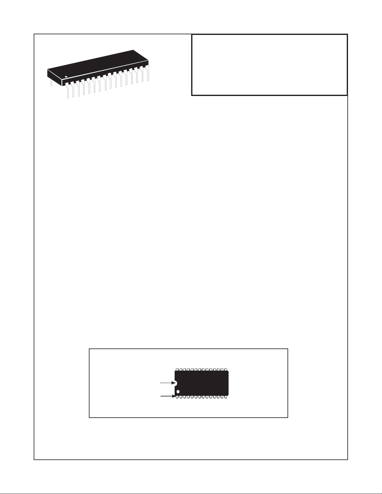
Integrated Circuit Pin Conversion
Observe proper orientation of any IC removed or installed! Note location of Pin 1 with respect to the notch in the
body of the IC. The replacement EPROM must be installed in the same manner as the EPROM removed. Failure
to observe this orientation will result in destruction of the EPROM. NOTE: Some ICs may have a small dot instead
of a notch for orientation purposes.
Notch
Pin 1
Document 50053 Rev M 1/10/08 P/N 50053:M 1 of 5
Page 2
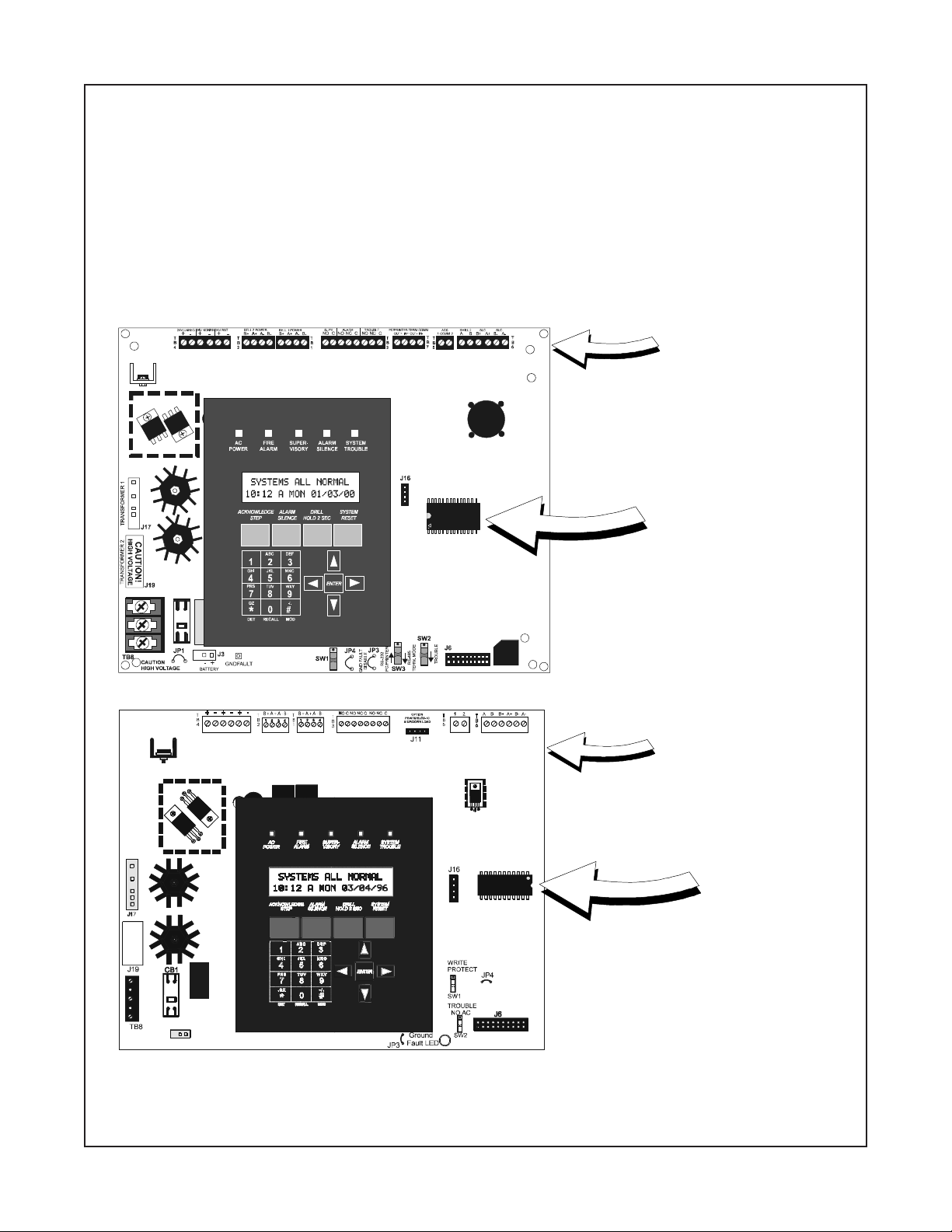
EPROM Replacement
Observe proper orientation of any IC removed or installed! To replace the EPROM, complete the following steps:
1. Make certain Software Revision and Circuit Board Revision are compatible (refer to table on page 4).
2. Once all power has been removed, disconnect any optional modules (if installed).
3. Locate EPROM U16 on newer boards or U14 on older boards (center right of the board).
4. Gently loosen and remove EPROM from the board.
5. Install replacement EPROM. Observe proper orientation! The notch or dot on the IC
should be positioned to the left for U16 in the newer boards or to the right for U14 in older boards as
shown below. Use care to insure that the EPROM's pins are not bent or broken during insertion.
6. Reconnect power supplies.
U16
Rev._
Rev._
Circuit Board assembly
information (Rev.) can be
found in the upper right
corner of the circuit board.
EPROM (U16)
(newer boards)
Circuit Board assembly
information (Rev.) can be
found in the upper right
corner of the circuit board.
U14
Programming and Testing
Reprogram and test the MS-9200(C)/E after EPROM replacement.
2 of 5
Document 50053 Rev M 1/10/08 P/N 50053:M
EPROM (U14)
(older boards)
Page 3

LCD-40 installation in an existing MS-9200(C)/E
In an existing MS-9200(C)/E installation, the following procedure must be followed to program the MS-9200(C)/E for
use with the LCD-40 Series Annunciator:
1. Connect the LCD-40 to the MS-9200(C)/E Control Panel (refer to the appropriate MS-9200(C)/E Technical
Manual and Product Installation Drawings).
2. Software Versions:
(1) If software with either the Part Number 73750 or 73829 is installed in the MS-9200(C), the LCD-40
Series Annunciator must have software with a Part Number of 73779 or 73879 to operate with the
FACP (Fire Alarm Control Panel). If software with a Part Number of #M9200V20 or higher is installed
in the MS-9200(C), the LCD-40 Series Annunciator must have software with a Part Number of
#LCD40V20 or higher to operate with the FACP.
(2) If software with Part Number 73846 is installed in the MS-9200E, the LCD-40 Series Annunciator
must have software with Part Number 73779 or 73879 to operate with the FACP. If software with
Part Number #M9200EV20 or higher is installed in the MS-9200E, the LCD-40 Series Annunciator
must have software with a Part Number of #LCD40V20 or higher to operate with the FACP.
3. Upon initial power-up of the MS-9200(C)/E with the new software installed, the following message may
appear on the MS-9200(C)/E LCD display:
"TROUBLE IN SYSTEM
PROGRAM CORRUPTED"
Whether the above message appears or not, the following steps must be followed to program the
MS-9200 for use with the LCD-40.
4. Press the ENTER key.
5. Press the 1 key to select Programming.
6. Enter your LEVEL 1 password.
7. Press the ENTER key.
8. Press the 1 key to select Autoprogram.
9. Upon successful completion of the Autoprogram function, press the LEFT ARROW key.
10. Press the 3 key to select System Edit.
11. At this point, use the RIGHT ARROW key to select TRM = N (or L/P = N as shown in the manual).
12. Press the UP ARROW key to change 'N' to 'L' in order to program the system for LCD-40 use.
13. Be sure to press the ENTER key to store the programming change in memory.
14. Press the LEFT ARROW key several times to get back to the SYSTEMS ALL NORMAL display.
15. At this point, the MS-9200(C)/E should be successfully programmed for use with the LCD-40. To ensure
that all programming changes have been accepted, depress the RESET key. The system should return
to the SYSTEMS ALL NORMAL display, after a successful software check.
Document 50053 Rev M 1/10/08 P/N 50053:M 3 of 5
Page 4

Software Changes
The following Table summarizes the MS-9200(C) software changes, specifying these changes by EPROM
Number and Release Number.
#MORP#esaeleRsegnahCfoyrammuS
294370.1esaeleRlaitinI
425371.1 tluafedyrotcafehtotsdrowssap2leveLro/dna1leveLs
465372.1 gnisusecivedroecivedafolavomerehtswo
085373.1 .edom)rettimsnarT/rotacinummoCmralAlatigiDlasrevinU(TCADUddA
106374.1 dneS.edoMTCADUninehwelbu
057370.veR .ylnOesaeleRateB.deddasllebhtobfognimmargo
057371.veR .ylnOesaeleRateB.ecafretnilairesnoytirapdnamuskcehcddasegnahC
057375.1 .2&
928376.1 .stiucric)lleb(CANfognicnuobedstcerroC
02V0029M#0.2 .noitcetorpatad04-DCLsevorpmI.noitasnepmocraeypael
12V0029M#1.2 .gnidaerretemtlovCAevomeR.tuotnirp)atadrotceted(ytivi
22V0029M#2.2 tibihnIecneliSgnirudnottubteseRelbasiD.sdnoces06otnoitamrifnoCnoitacifireVmralAe
tuA
tisnessddA
gnahC
eriFegnahC.sgnittes
.sruccoliafCA
rP.deddatroppus04-DCL
ecneliSgniruddesserpsi
.tibihnI
nruterhcihwnoitcnuFraelCdrowssaPddA
.noitacifitnedielbuortecivedcificepsddA
llahcihwnoitcnuFeteleDecivedehtstcerroC
orTrotaicnunnAfodaetsnielbuorTTCADUottroperretnirpegnahC
buortyrettabnehwTCADUotelbuorTlareneG
1sllebelbammargorpdnatroppus04-DCLfoesaelergnirutcafunaM
.gnitroperrorrednagnikcehcMORPEsetavitcA
sddA'.yrosivrepuselbatteser-otua'sddA
.noisiverylbmessa
.llirdagnirudstiucricecnailppanoitacifitonhtobnonrutoterutaefllirD
.gnimmargorpecivedgniniamerehtfonoitaretlatuohtiw,edommargorpo
nehwTCADUotelbuorTlareneGdnestonlliW.sruccoel
nottubecneliSfiegassemyalpsiD.smralatneuqesbushtiwdetratsertonsiremiTtibihnIecneliS.emit
draobtiucricynanidesuebnacerawtfosreilraedna2.2noisiveR
4 of 5
32V0029M#3.2.rossecorporcimwenrofetadpU
ylbmessadraobtiucricnidesuebylnonacerawtfos3.2noisiveR
.retalroFnoisiveR
52V0029M#5.2 snepoCLSfismelborpgnisuacsecivedCISAdesaelerylwenhtiwmelborp7/6elytSCLSnatcerroC
.pu
Document 50053 Rev M 1/10/08 P/N 50053:M
Page 5

Software Changes
The following Table summarizes the MS-9200E software changes, specifying these changes by EPROM
Number and Release Number.
#MORP#esaeleRsegnahCfoyrammuS
648370.1esaeleRlaitinI
02VE0029M#0.2
12V0029M#1.2
22V0029M#2.2
32V0029M#3.2
52V0029M#5.2
raeypaelsddA'.yrosivrepuselbatteser-otua'sddA
ed(ytivitisnessddA
eVmralAegnahC
.tibih
nIecneliSgniruddesserpsinottub
.gnidaerretemtlovCAevomeR.tuotnirp)atadrotcet
.noitcetorpatad04-DCLsevorpmI.noitasnepmoc
tibihnIecneliSgnirudnottubteseRelbasiD.sdnoces06otnoitamrifnoCnoitacifir
ecneliSfiegassemyalpsiD.smralatneuqesbushtiwdetratsertonsiremiTtibihnIecneliS.emit
draobtiucricynanidesuebnacerawtfosreilraedna2.2noisiveR
.noisiverylbmessa
.rossecorporcimwenrofetadpU
ylbmessadraobtiucricnidesuebylnonacerawtfos3.2noisiveR
.retalroFnoisiveR
.pu
snepoCLSfismelborpgnisuacsecivedCISAdesaelerylwenhtiwmelborp7/6elytSCLSnatcerroC
Document 50053 Rev M 1/10/08 P/N 50053:M 5 of 5
 Loading...