

Page 1

Addressable Fire Alarm Control Panel
MS-9050UD
MS-9050UDC
MS-9050UDE
Manual
Document 52413
4/14/2014 Rev:
P/N 52413:G ECN 14-226
G
Page 2

Fire Alarm & Emergency Communication System Limitations
While a life safety system may lower insurance rates, it is not a substitute for life and property insurance!
An automatic fire alarm system—typically made up of smoke
detectors, heat detectors, manual pull stations, audible warning
devices, and a fire alarm control panel (FACP) with remote notification capability—can provide early warn ing of a developing fire.
Such a system, however, does not assure protection against
property damage or loss of life resulting from a fire.
An emergency communication system—typically made up of
an automatic fire alarm system (as described above) and a life
safety communication system that may include an autonomous
control unit (ACU), local operating console (LOC), voice communication, and other various interoperable communication met hods—can broadcast a mass notification message. Such a
system, however, does not assure protection against property
damage or loss of life resulting from a fire or life safety event.
The Manufacturer recommends that smoke and/or heat
detectors be located throughout a protected premises following
the recommendations of the current edition of the National Fire
Protection Association S tandard 72 (NFPA 72), manufacturer's
recommendations, State and local codes, and the
recommendations contained in the Guide for Proper Use of
System Smoke Detectors, which is made available at no charge
to all installing dealers. This document can be found at http: //
www.systemsensor.com/appguides/. A study by the Federal
Emergency Management Agency (an agency of the United
States governme nt) indicated that smoke detectors may not go
off in as many as 35% of all fires. While fire alarm systems are
designed to provide early warning against fire, they do not
guarantee warning or protection against fire. A fire alarm system
may not provide timely or adequate warning, or simply may not
function, for a variety of reasons:
Smoke detectors may not sense fire where smoke cannot
reach the detectors such as in chimneys, in or behind walls, on
roofs, or on the other side of closed doors. Smoke detectors
also may not sense a fire on another level or floor of a building.
A second-floor detector, for example, may not sense a first-floor
or basement fire.
Particles of combustion or “smok e ” from a developing fire
may not reach the sensing chambers of smoke detectors
because:
• Barriers such as closed or partially closed doors, walls, chimneys, even wet or humid areas may inhibit particle or smoke
flow.
• Smoke particles may become “cold,” stratify, and not reach
the ceiling or upper walls where detectors are located.
• Smoke particles may be blown aw a y from de tectors by air
outlets, such as air conditioning vent s.
• Smoke particles may be drawn into air returns before reaching the detector.
The amount of “smoke” present may be insufficient to alarm
smoke detectors. Smoke detectors are designe d to ala rm at various levels of smoke density. If such density levels are not created by a developing fire at the location of detectors, the
detectors will not go into alarm.
Smoke detectors, even when working properly, have sensing
limitations. Detectors that have photoelectronic sensing chambers tend to detect smoldering fires better than flaming fires,
which have little visible smoke. Detectors that have ionizing-type
sensing chambers tend to detect fast-flaming fires better than
smoldering fires. Because fires develop in different ways and
are often unpredictable in their growt h, neither type of detector i s
necessarily best and a given type of detector may not provide
adequate warning of a fire.
Smoke detectors cannot be expected to provide adequate warning of fires caused by arson, children playing with matches
(especially in bedrooms), smoking in bed, and violent explosions
(caused by escaping gas, improper storage of flammable materials, etc.).
Heat detectors do not sense particles of combustion and al arm
only when heat on their sensors increases at a predetermined
rate or reaches a predetermined level. Rate-of-rise heat detectors may be subject to reduced sensitivity over time. For this
reason, the rate-of-rise feature of each detector shoul d be tested
at least once per year by a qualified fire protection specialist .
Heat detectors are designed to protect property, not life.
IMPORTANT! Smoke detectors must be installed in the same
room as the control panel and in rooms used by the system for
the connection of alarm transmission wiring, communications,
signaling, and/or power. If detectors are not so located, a developing fire may damage the alarm system, compromising its ability to report a fire.
Audible warning devices such as bells, horns, strobes,
speakers and displays may not alert people if these devices
are located on the other side of closed or partly open doors or
are located on another floor of a building. Any warning device
may fail to alert people with a disability or those who have
recently consumed drugs, alcohol, or medication. Please note
that:
• An emergency communication system may take priority over
a fire alarm system in the event of a life safety emergency.
• Voice messaging systems must be desi gned to meet intelligibility requirements as defined by NFPA, local codes, and
Authorities Having Jurisdiction (AHJ).
• Language and instructional requirements must be clearly disseminated on any local displays.
• Strobes can, under c ertain circumstances, cause seizures in
people with conditions such as epilepsy.
• Studies have sh own that certain people, even when they he ar
a fire alarm signal, do not respond to or comprehend the
meaning of the signal. Audible devices, such as horns and
bells, can have different tonal patterns and frequencies. It is
the property owner's responsibility to conduct fire drills and
other training exercises to make people aware of fire alarm
signals and instruct them on the proper reaction to alarm signals.
• In rare instances, the sounding of a warning device can cause
temporary or permanent hearing loss.
A life safety system will not operate without any electrical
power. If AC power fails, the system will operate from standby
batteries only for a specified time and only if the batteries have
been properly maintained and replaced regularly.
Equipment used in the system may not be technically compatible with the control panel. It is essential to use only equipment
l
is
ted for service with your control panel.
Telephone lines needed to transmit alarm signals from a premises to a central monitoring station may be out of service or temporarily disabled. For added protection against telephone line
failure, backup radio transmission systems are recommended.
The most common cause of life safety system malfunction is
inadequate maintenance. To keep t he entire life safety sys tem in
excellent working order , ongoing mai ntenance is required per the
manufacturer's recommendations, and UL and NFPA standards. At a minimum, the requirements of NFPA 72 shall be followed. Environments with large amounts of dus t, dirt, or hig h air
velocity require more frequent maintenance. A maintenance
agreement should be arranged through the local manufacturer's
representative. Maintenance should be scheduled monthl y or as
required by National and/or local fire codes and should be performed by authorized professional life safety system installers
only . Adequate written reco rds of all inspecti ons should be kept.
Limit-D-1-2013
2 MS-9050 Series Manual — P/N 52413:G 4/14/2014
Page 3

Installation Precautions
Adherence to the following will aid in problem-free installation with long-term reliability:
WARNING - Several different sources of power can be
connected to the fire alarm control panel. Disconnect all
sources of power before servicing. Control unit and associated equipment may be damaged by removing and/or inserting cards, modules, or interconnecting cables while the unit is
energized. Do not attempt to install, service, or operate this
unit until manuals are read and understood.
CAUTION - System Re-acceptance Test after Software
Changes: To ensure proper system operation, this product
must be tested in accordance with NFPA 72 after any programming operation or change in site-specific software. Reacceptance testing is required after any change, addition or
deletion of system components, or after any modification,
repair or adjustment to system hardware or wiring. All components, circuits, system operations, or sof tware functions known
to be affected by a change must be 100% tested. In addition,
to ensure that other operations are not inadvertently affected,
at least 10% of initiating devices that are not directly affected
by the change, up to a maximum of 50 devices, must also be
tested and proper system operation verified.
This system meets NFPA requirements for operation at 0-49º
C/32-120º F and at a relative humidity 93% ± 2% RH (noncondensing) at 32°C ± 2°C (90°F ± 3°F). However, the useful
life of the system's standby batteries and the electronic components may be adversely affected by extreme temperature
ranges and humidity. Therefore, it is recommended that this
system and its peripherals be installed in an environment with
a normal room temperature of 15-27º C/60-80º F.
Verify that wire sizes are adequate for all initia ting and indicating device loops. Most devices cannot tol erate more than a
10% I.R. drop from the specified device voltage.
Like all solid state electronic devices, this system may
operate erratically or can be damaged when subject ed to li ght ning induced transients. Although no system is completely
immune from lightning transients and interf erence, proper
grounding will reduce susceptibility. Overhead or outside aerial
wiring is not recommended, due to an increased susceptibility
to nearby lightning strikes. Consult with the Technical Services Department if any problems are anticipated or encountered.
Disconnect AC power and batteries prior to removing or
inserting circuit boards. Failure to do so can damage circuits.
Remove all electronic assemblies prior to any drilling, filing,
reaming, or punching of the enclosure. When possible, make
all cable entries from the sides or rear. Before making modifications, verify that they will not interfere with battery, transformer, or printed circuit board location.
Do not tighten screw terminals more than 9 in-lbs. Overtightening may damage threads, resulting in reduced terminal
contact pressure and difficulty wit h screw terminal removal.
This system contains static-sensitive components.
Always ground yourself with a proper wrist strap before handling any circuits so that static charges are removed from the
body . Use static suppressive packaging to protect electronic
assemblies removed from the unit.
Follow the instructions in the inst al lati on, ope rati ng, and programming manuals. These instructions must be followed to
avoid damage to the control panel and a ssociated equipment.
FACP operation and rel iability depend upon proper inst allat ion.
Precau-D1-9-2005
FCC Warning
WARNING: This equipment generates, uses, and can
radiate radio frequency energy and if not installed and
used in accordance with the instruction manual may
cause interference to radio communications. It has been
tested and found to comply with the limits for class A
computing devices pursuant to Subpart B of Part 15 of
FCC Rules, which is designed to provide reasonable
protection against such interference when devices are
operated in a commercial environment. Operation of this
equipment in a residential area is likely to cause interference, in which case the user will be required to correct
the interference at his or her own expense.
Canadian Requirements
This digital apparatus does not exce ed the Class A limit s
for radiation noise emissions from digital apparatus set
out in the Radio Interference Regulations of the Canadian Department of Communications.
Le present appareil numerique n'emet pas de bruit s radi oelectriques depassant les limites applic ables aux appareils numeriques de la classe A prescrites dans le
Reglement sur le brouillage radioelectrique edict e p ar l e
ministere des Communications du Canada.
LiteSpeed™, Lite-Connect™, and SWIFT™ are trademarks; and Fire-Lite® Alarms is a registered trademark of Honeywell International Inc. Microsoft®
and Windows® are registered trademarks of the Microsoft Corporation.
©2014 by Honeywell International Inc. All rights reserved. Unauth orized use of this document is strictly prohibited.
MS-9050 Series Manual — P/N 52413:G 4/14/2014 3
Page 4

Software Downloads
In order to supply the latest features and functionality in fire alarm and life safety technology to our customers, we make
frequent upgrades to the embedded software in our products. To ensure that you are installing and programming the latest
features, we strongly recommend that you download the most current version of software for each product prior to
commissioning any system. Contact Technical Support with any questions about software and the appropriate version for a
specific application.
Documentation Feedback
Your feedback helps us keep our documentation up-to-date and accurate. If you have any comments or suggestions about our
online Help or printed manuals, you can email us.
Please include the following information:
•Product name and version number (if applicable)
•Printed manual or online Help
•Topic Title (for online Help)
•Page number (for printed manual)
•Brief description of content you think should be improved or corrected
•Your suggestion for how to correct/improve documentation
Send email messages to:
FireSystems.TechPubs@honeywell.com
Please note this email address is for documentation feedback only. If you have any technical issues, please contact Technical
Services.
4 MS-9050 Series Manual — P/N 52413:G 4/14/2014
Page 5

Table of Contents
Section 1: Product Description .............................................................................................12
1.1: Features and Options ...................................................................................................................................12
1.2: Specifications...............................................................................................................................................14
1.3: Controls and Indicators................................................................................................................................15
1.4: Circuits.........................................................................................................................................................16
1.5: Digital Alarm Communicator/Transmitter ..................................................................................................17
1.6: Components.................................................................................................................................................17
1.6.1: Intelligent Addressable Detectors: Newer Series ..............................................................................18
1.6.2: Intelligent Addressable Modules: Newer Series ...............................................................................18
1.6.3: 300 Series Intelligent Addressable Devices ......................................................................................18
1.6.4: Device Accessories............................................................................................................................18
1.7: Optional Modules and Accessories .............................................................................................................19
1.8: Getting Started.............................................................................................................................................21
1.9: Telephone Requirements and Warnings.......................................................................................................21
1.9.1: Telephone Circuitry...........................................................................................................................21
1.9.2: Digital Communicator.......................................................................................................................21
1.9.3: Telephone Company Rights and Warnings.......................................................................................22
1.9.4: For Canadian Applications................................................................................................................22
Section 2: Installation.............................................................................................................24
2.1: Mounting the Backbox ................................................................................................................................24
2.2: Mounting the Chassis/Transformer/Main Circuit Board.............................................................................25
2.3: Power...........................................................................................................................................................28
2.3.1: AC Power and Earth Ground Connection.........................................................................................28
2.3.2: Battery Power....................................................................................................................................28
2.4: Relays ..........................................................................................................................................................29
2.5: Notification Appliance Circuits...................................................................................................................30
2.5.1: Configuring NACs.............................................................................................................................30
2.6: UL Power-limited Wiring Requirements.....................................................................................................31
2.7: Digital Communicator.................................................................................................................................32
2.8: Optional Modules/Accessories Installation.................................................................................................33
2.8.1: 4XTMF Transmitter Module Installation..........................................................................................33
2.8.2: ANN-SEC Option Card.....................................................................................................................35
2.9: ANN-BUS Devices......................................................................................................................................36
Guidelines.............................................................................................................................................36
2.9.1: ANN-BUS Wiring.............................................................................................................................36
Calculating Wiring Distance for ANN-BUS Modules.........................................................................37
Wiring Configuration ................................................ .................................. .........................................39
Powering ANN-BUS Devices from Auxiliary Power Supply .............................................................39
2.9.2: ANN-BUS Device Addressing ..........................................................................................................40
2.9.3: ANN-80(C) Remote Fire Annunciator/Indicator ..............................................................................40
Specifications .......................................................................................................................................40
Installation............................................................................................................................................41
Opening/Closing Annunciator..............................................................................................................41
Mounting ..............................................................................................................................................41
Wiring ANN-80 to FACP................................................................................. ....................................42
2.9.4: ANN-S/PG Serial/Parallel Interface Module ....................................................................................43
Specifications .......................................................................................................................................44
PRN-6F Printer Installation..................................................................................................................44
2.9.5: ANN-I/O LED Driver Module..........................................................................................................45
ANN-I/O Board Layout........................................................................................................................46
Specifications .......................................................................................................................................46
ANN-I/O Connection to FACP............................................................................................................47
ANN-I/O Module LED Wiring............................................................................................................47
MS-9050 Series Manual — P/N 52413:G 4/14/2014 5
Page 6

Table of Contents
2.9.6: ANN-LED Annunciator Module.......................................................................................................49
Specifications........................................................................................................................................49
Mounting and Installation.....................................................................................................................49
ANN-LED Board Layout and Connection to FACP............................................................................50
2.9.7: ANN-RLY Relay Module..................................................................................................................50
Specifications........................................................................................................................................50
Mounting and Installation.....................................................................................................................51
ANN-RLY Board Layout and Connection to FACP............................................................................52
2.9.8: ANN-LC Lite-Connect Module .........................................................................................................52
Specifications........................................................................................................................................52
Installation ............................................................................................................................................52
Mounting ..............................................................................................................................................52
Wiring the ANN-LC to the MS-9050UD.............................................................................................53
Section 3: Programming........................................................................................................55
3.1: Programming Data Entry.............................................................................................................................55
3.2: User Programming.......................................................................................................................................56
3.3: Initial Power-up............................................................................................................................................57
3.4: Programming Screens Description ..............................................................................................................57
3.5: Programming and Passwords.......................................................................................................................57
3.6: Master Programming Level .........................................................................................................................58
3.6.1: Autoprogram......................................................................................................................................58
3.6.2: Point Program....................................................................................................................................59
Detector Programming..........................................................................................................................59
Module Programming...........................................................................................................................66
3.6.3: Zone Setup.........................................................................................................................................78
Enable...................................................................................................................................................78
Disable..................................................................................................................................................78
Zone 17, 18, and 19 ..............................................................................................................................78
Zones Installed......................................................................................................................................79
Zones Enabled ......................................................................................................................................79
Zones Disabled .....................................................................................................................................79
Zone Type.............................................................................................................................................79
Zones Available....................................................................................................................................80
3.6.4: Loop Setup.........................................................................................................................................81
Style......................................................................................................................................................81
Loop Protocol .......................................................................................................................................81
3.6.5: System Setup .....................................................................................................................................81
Trouble Reminder.................................................................................................................................82
Banner...................................................................................................................................................82
Time-Date.............................................................................................................................................83
Timers...................................................................................................................................................84
NAC (Notification Appliance Circuit).................................................................................................86
Relays ...................................................................................................................................................90
Canadian Option...................................................................................................................................91
Waterflow Silenceable..........................................................................................................................91
Lite-Connect.........................................................................................................................................91
3.6.6: Verify Loop .......................................................................................................................................93
3.6.7: History ...............................................................................................................................................93
View Events.......................................................................................... ................................................94
Erase History ........................................................... .................................. ...........................................94
3.6.8: Walktest.............................................................................................................................................94
3.6.9: Option Modules ................................................................................................................................95
ANN-BUS.............................................................................................................................................96
Onboard DACT ............................................................................................ ......................................106
3.6.10: Password Change.................................. .................................. ....................................
3.6.11: Clear
Program
................................................................. ................................. ..............................118
...................118
6 MS-9050 Series Manual — P/N 52413:G 4/14/2014
Page 7

Table of Contents
3.6.12: Program Check.................................... .................................. .................................. ......................119
3.7: Maintenance Programming Level..............................................................................................................119
3.7.1: Disable Point ...................................................................................................................................120
3.7.2: History.............................................................................................................................................120
3.7.3: Program Check................................................................................................................................121
3.7.4: Walktest...........................................................................................................................................122
3.7.5: System .............................................................................................................................................123
3.7.6: Zone Setup.......................................................................................................................................124
Section 4: Operating Instructions.......................................................................................126
4.1: Panel Control Buttons................................................................................................................................126
4.1.1: Acknowledge/Step...........................................................................................................................126
4.1.2: Alarm Silence..................................................................................................................................126
4.1.3: Drill/Hold 2 Sec...............................................................................................................................126
4.1.4: Reset ................................................................................................................................................126
4.2: Status Indicators and LEDs........................................................................................................................126
4.3: Normal Operation......................................................................................................................................127
4.4: Trouble Operation......................................................................................................................................128
4.5: Alarm Operation........................................................................................................................................129
4.6: Supervisory Operation...............................................................................................................................130
4.7: Process Monitor Operation........................................................................................................................130
4.8: Hazard/Tornado Condition Operation .......................................................................................................131
4.9: Medical Alert Condition Operation...........................................................................................................131
4.10: NAC Operation..................................................................................... ...................................................132
4.11: Programmed Zone Operation...................................................................................................................132
4.12: Disable/Enable Operation................................................................................... .....................................132
4.13: Waterflow Circuits Operation..................................................................................................................132
4.14: Detector Functions................................... .................................. .................................. ............................132
4.15: Time Functions: Real-Time Clock...........................................................................................................133
4.16: Synchronized NAC Operation.................................................................................................................133
4.17: Coded Operation................................................................................... ...................................................133
4.18: Presignal ........................................................... .................................. .....................................................134
4.19: Positive Alarm Sequence.........................................................................................................................134
4.20: Special System Timers............................................................... .................................. ............................135
4.20.1: Silence Inhibit Timer................................................................................... ..................................135
4.20.2: Autosilence Timer ................................................ .................................. .......................................135
4.20.3: Trouble Reminder........................................................................................ ..................................135
4.20.4: Waterflow Retard Timer.............................................................................. ..................................135
4.20.5: Alarm Verification (None or One Minute)....................................................................................135
4.21: Walktest ...................................................... .................................. ...........................................................136
4.22: Read Status ....................................................... .................................. .....................................................136
4.22.1: System Point.................................................................................. ................................................137
4.22.2: Zones .......................................................................................... ...................................................138
4.22.3: Power..................................................................................... ........................................................138
4.22.4: Trouble Reminder........................................................................................ ..................................139
4.22.5: Timers....................................... ................................. .................................. ..................................139
4.22.6: NAC........................................................ .................................. .....................................................139
4.22.7: Relays .............................................................................. .................................. . ...........................139
4.22.8: Program Check.................................... .................................. .................................. ......................140
4.22.9: History................................ .................................. .................................. .......................................140
4.22.10: ANN-BUS ...............................................................................................................
ne...................................................................................................................................141
4.22.11: Phone L
i
4.22.12: Central Station.............................................................................................................................141
4.22.13: Service Terminal..........................................................................................................................141
4.22.14: Print .............................................................................................................................................142
4.22.15: Time-Date....................................................................................................................................143
....................140
MS-9050 Series Manual — P/N 52413:G 4/14/2014 7
Page 8

Table of Contents
Section 5: Central Station Communications......................................................................145
5.1: Transmittal Priorities..................................................................................................................................148
Section 6: Local/Remote Site Upload/Download...............................................................150
6.1: Remote Download .....................................................................................................................................150
6.2: Transferring a Program..............................................................................................................................151
6.3: Security Features........................................................................................................................................151
Section 7: Power Supply Calculations ...............................................................................153
7.1: Overview....................................................................................................................................................153
7.2: Calculating the AC Branch Circuit............................................................................................................153
7.3: Calculating the System Current Draw .......................................................................................................154
7.3.1: Overview..........................................................................................................................................154
7.3.2: How to Use Table 7.3 to Calculate System Current Draw..............................................................154
7.4: Calculating the Battery Size.......................................................................................................................156
7.4.1: NFPA Battery Requirements............................. .................................. ............................................156
7.4.2: Selecting and Locating Batteries .....................................................................................................156
Appendix A: Software Zones...............................................................................................157
A.1: Correlations...............................................................................................................................................157
Appendix B: Default Programming.....................................................................................162
Appendix C: NFPA Standard-Specific Requirements.......................................................164
C.1: Central Station/Remote Station Transmitter: Connection to FACP Dry Contacts....................................168
C.2: MBT-1 Municipal Box Trip - Silenceable.................................................................................................169
Appendix D: FACP with Keltron..........................................................................................170
Appendix E: Wire Requirements.........................................................................................171
E.1: NAC Wiring...............................................................................................................................................172
Appendix F: HVAC Control..................................................................................................173
F.1: Control Module Operation .........................................................................................................................173
F.1.1: HVAC SHUTDN............................................. .................................. ..............................................173
F.2: Monitor Module Operation ........................................................................................................................173
F.2.1: HVAC RESTART.............................................................. .................................. ...........................173
F.2.2: HVAC OVRRIDE...................................................... .................................. ...................................174
Appendix G: Ademco Contact ID Format Event Code Descriptions ...............................175
G.1: Transmission Format Between DACT and Receiver................................................................................175
G.2: Ademco Contact ID Typical Printout........................................................................................................175
Appendix H: Canadian Application.....................................................................................181
H.1: ANN-LED Annunciator Installation for Canadian Applications..............................................................181
H.2: AC Power Connections for Canadian Applications..................................................................................184
Index ......................................................................................................................................185
8 MS-9050 Series Manual — P/N 52413:G 4/14/2014
Page 9

It is imperative that the installer understand the requirements of the Authority Having Jurisdiction
(AHJ) and be familiar with the standards set forth by the following regulatory agencies:
• Underwriters Laboratories/Underwriters Laboratories Canada
• National Fire Protection Association
Before proceeding, the installer should be familiar with the following documents.
NFPA Standards
NFPA 72 National Fire Alarm Code
NFPA 70 National Electrical Code
Underwriters Laboratories Documents:
UL 38 Manually Actuated Signaling Boxes
UL 217 Smoke Detectors, Single and Multiple Station
UL 228 Door Closers–Holders for Fire Protective Signaling Systems
UL 268 Smoke Detectors for Fire Protective Signaling Systems
UL 268A Smoke Detectors for Duct Applications
UL 346 Waterflow Indicators for Fire Protective Signaling Systems
UL 464 Audible Signaling Appliances
UL 521 Heat Detectors for Fire Protective Signaling Systems
UL 864 Standard for Control Units for Fire Protective Signaling Systems
UL 1481 Power Supplies for Fire Protective Signaling Systems
UL 1610 Central Station Burglar Alarm Units
UL 1638 Visual Signaling Appliances
UL 1971 Signaling Devices for Hearing Impaired
UL 2017 General-Purpose Signaling Devices and System
CAN/ULC - S524-01 Standard for Installation of Fire Alarm System
CAN/ULC - S561-03 Installation and Services for Fire Signal Receiving Centers and
Systems
CAN/ULC - S527-99 Standard for Control Units for Fire Alarm Systems
CAN/ULC - S559-04 Equipment for Fire Signal Receiving Centers and Systems
This Class (A) digital apparatus complies with Canadian ICES-003.
Cet appareil numérique de la classe (A) est conforme à la norme NMB-003 du Canada.
Other:
Canadian Electrical Code, Part I
EIA-232E Serial Interface Standard
EIA-485 Serial Interface Standard
NEC Article 250 Grounding
NEC Article 300 Wiring Methods
NEC Article 760 Fire Protective Signaling Systems
Applicable Local and State Building Codes
Requirements of the Local Authority Having Jurisdiction (LAHJ)
Fire-Lite Documents:
Fire-Lite Device Compatibility Document #15384
SLC Wiring Manual Document #51309
CHG-120F Battery Charger Document #50888
CHG-75 Battery Charger Document #51315
ANN-80(C) Product Installation Doc. Document #52749
ANN-(R)LED Product Installation Doc. Document #53032
ANN-I/O Product Installation Doc. Document #151416
ANN-RLY Product Installation Doc. Document #53033
ANN-S/PG Product Installation Doc. Document #151417
ANN-LC Product Installation Doc. Document #LS10158-000FL-E
This product has been certified to comply with the requirements in the Standard for Control Units and Accessories for Fire Alarm
Systems, UL 864, 9th Edition. Operation of this product with products not tested for UL 864, 9th Edition has not been evaluated.
Such operation requires the approval of the local Authority Having Jurisdiction (AHJ).
MS-9050 Series Manual — P/N 52413:G 4/14/2014 9
Page 10
J
1
3
C
A
U
T
I
O
N
!
H
I
G
H
V
O
L
T
A
G
E
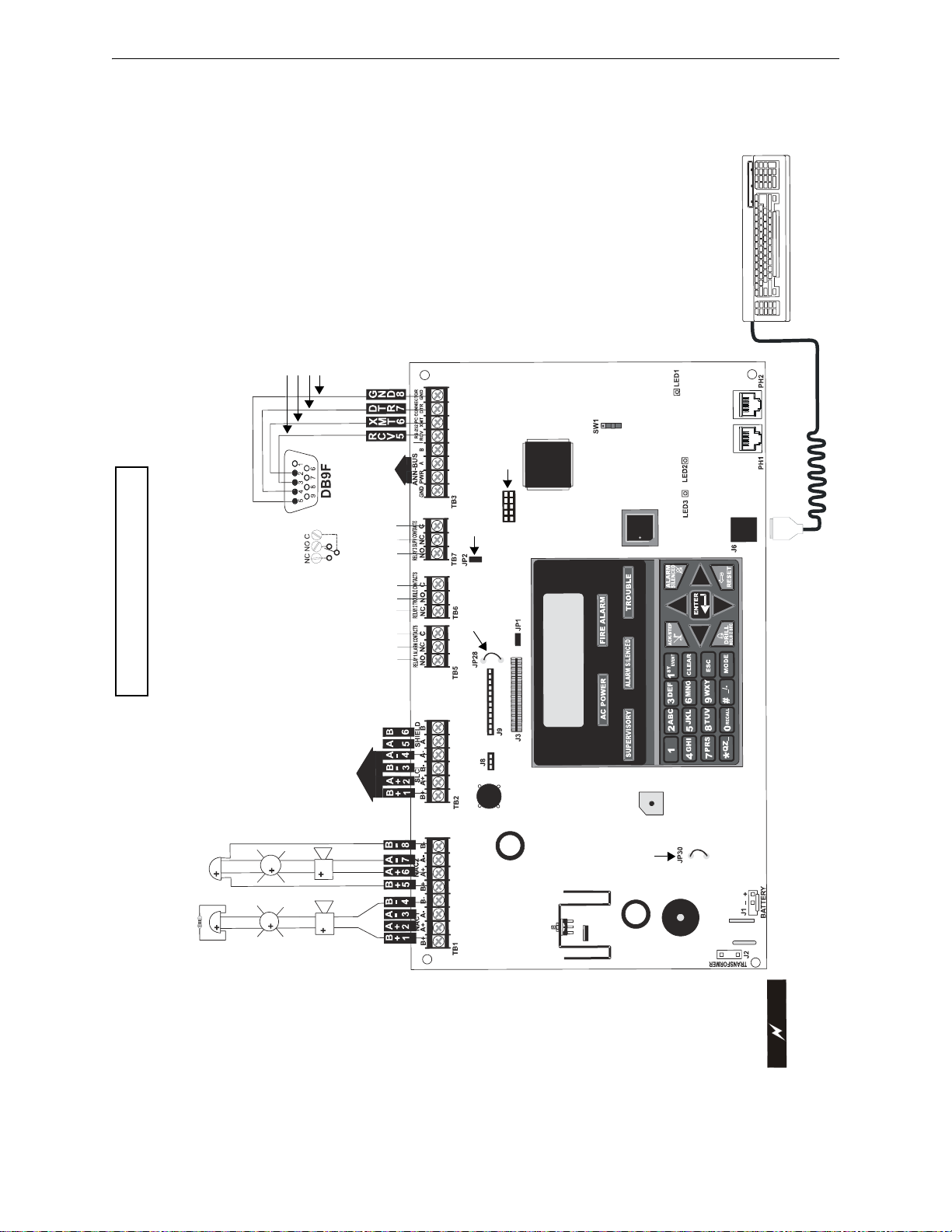
9050udlayout.wmf
For specific UL wiring
information, refer to
“UL Power-limited
Wiring Requirements”
on page 31.
E
IA-232 to
perso
nal computer
personal co
mputer with
FACP Upload/Download
utility, 50 foot maximum
within sa
me room,
(Nonsupervised, Power
-
limited, Class 2 Circuit)
A
N
N
-
B
U
S
(
E
I
A
-
4
8
5
)
f
o
r
A
n
n
u
n
c
i
a
t
o
r
C
o
n
n
e
c
t
i
o
n
(
P
o
w
e
r
-
l
i
m
i
t
e
d
,
C
l
a
s
s
2
,
S
u
p
e
r
v
i
s
e
d
)
A
la
r
m
*
N
O
N
C
C
T
r
o
u
b
le
N
O
N
C
C
S
u
p
e
r
v
is
o
r
y
*
N
O
N
C
C
2 Programmable Relays
& 1
Fixed Trouble Relay
Nonsupervised Contact Ratings:
2.0 am
ps @ 30 VDC (resistive)
0.5 amp @ 30 VAC
(resistive)
Contac
ts shown below in normal
condition (AC power
with no alarm,
trouble, or supervisory activity).
A Fail Safe Trouble
relay switches to the
NO posi
tion during
trouble conditions andunder loss of all power.
(*Factory default rel
ay programming)
SLC Loop
Refer t
o the SLC Wiring
Manual for detail
ed
information on wiring
addre
ssable devices for
Style 4, 6, and
7.
(Power-limited, Class 2,
Sup
ervised Circuit)
Notification Ap
pliance Circuits
Special Applicati
on Power
NAC #1 show
n Style Y (Class B) (Power-limited, Cl
ass 2, Supervised)
NAC #2 shown Style Z (C
lass A) (Power-limited, Class 2, Supe
rvised)
2.5 amps max. per circuit. Total av
ailable current is 2.5 amps.
N
A
C
#
1
N
A
C
#
2
E
L
R
-
4
.
7
,
½
W
Transformer
Connector
Nonpower-limited
Supervised
Battery
24 VDC, nonpower-limited,
supervised, 18 Amp Hour max.
PS2 Keyboard Interface
DACT Phone Line Jacks
(nonpower-limited, supervised)
K
I
S
S
O
F
F
P
R
I
M
A
R
Y
A
C
T
I
V
E
S
E
C
O
N
D
A
R
Y
A
C
T
I
V
E
PHONE LINE
SECONDARY
PRIMARY
PHONE LINE
F
L
A
S
H
M
E
M
O
R
Y
L
O
A
D
E
N
A
B
L
E
S
W
I
T
C
H
R
e
m
o
v
e
t
h
i
s
j
u
m
p
e
r
t
o
e
n
a
b
l
e
s
u
p
e
r
v
i
s
o
r
y
r
e
l
a
y
w
h
e
n
4
X
T
M
F
i
s
i
n
s
t
a
l
l
e
d
.
L
C
D
D
I
S
P
L
A
Y
4
X
T
M
F
C
u
t
J
P
2
8
t
o
S
u
p
e
r
v
i
s
e
4
X
T
M
F
T
o
d
i
s
a
b
l
e
g
r
o
u
n
d
f
a
u
l
t
d
e
t
e
c
t
i
o
n
,
r
e
m
o
v
e
j
u
m
p
e
r
/
s
h
u
n
t
f
r
o
m
J
P
1
A
N
N
-
S
E
C
O
p
t
i
o
n
C
a
r
d
c
o
n
n
e
c
t
o
r
C
h
a
r
g
e
r
D
i
s
a
b
l
e
J
u
m
p
e
r
(
c
u
t
t
o
d
i
s
a
b
l
e
F
A
C
P
o
n
b
o
a
r
d
b
a
t
t
e
r
y
c
h
a
r
g
e
r
)
BASIC SYSTEM CONNECTIONS
w
h
i
t
e
r
e
d
g
r
e
e
n
b
l
a
c
k
10 MS-9050 Series Manual — P/N 52413:G 4/14/2014
Page 11
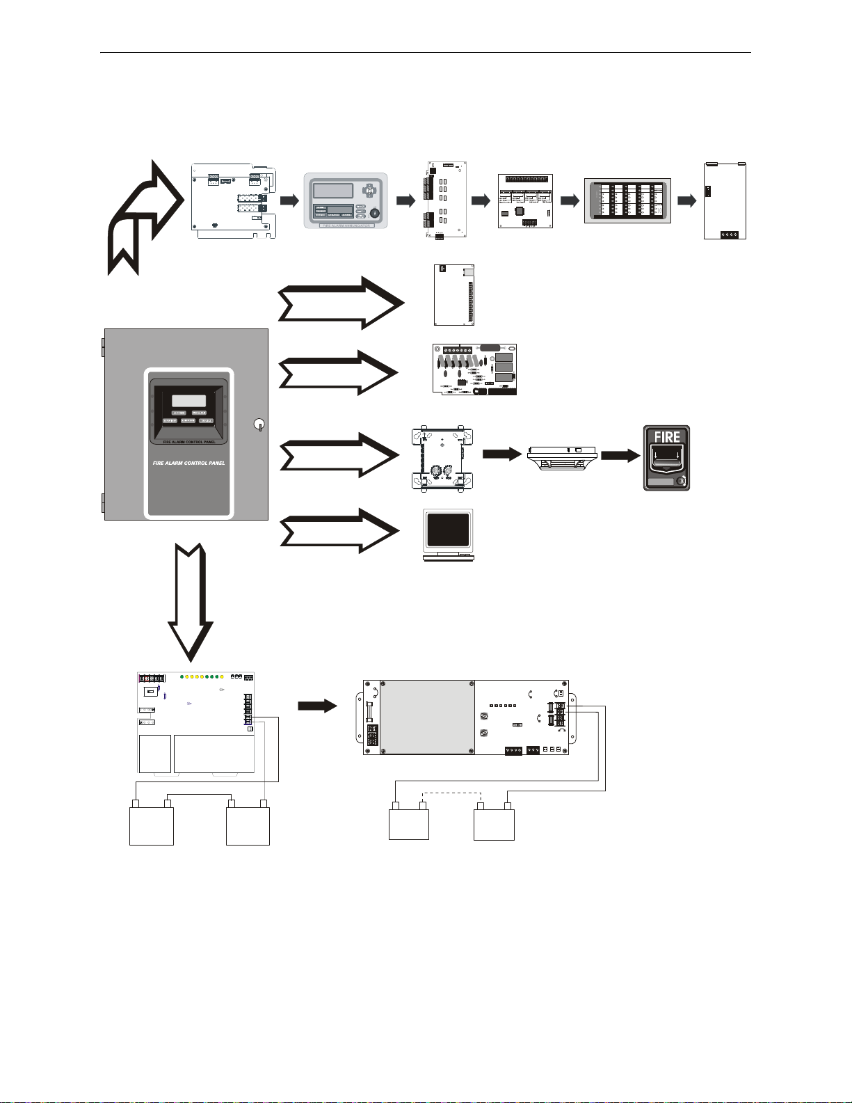
Peripheral Devices
-
+
-
+
JP1
JP3
SW1
JP4
TB3
TB4
TB2
ENABLE
AC DELAY
16 HR
DELAY
TENS
ONES
CUT FOR
240VAC
GND FLT
DISABLE
AM-1 ENABLE
ADDRESS
ON OFF
AM-1
JP5
JP2
F1
F2
J4
J1 J2
J3
F3
TB1
HOT
OUT
+
BAT
+
OUT
-
BAT
-
EARTH
NEUT
1
5
1
5
A- B- A+ B+
NC NO C
043
92615
78121315141011043
92615
7
8
12
13
15
14
10
11
TB1
TBL
J1
J2
7 6 5 1
POWER LIMITED
Sw1
P1 P2
P3
P4
110
11 20
21 30 31
40
1 2 3 4 5
TB1
J1
SW1
JP2
ANN-BUS
1 2 3 4 5 6 7 8
TB6
TB3
TB5
TB4
TB2
Alarm
Silenced
Earth
Fault
ZONE 1
ALM
TBL
SUP
1
ZONE 6
ALM
TBL
SUP
6
NAC 1
Fault
Battery
Fault
ZONE 2
ALM
TBL
SUP
2
ZONE 7
ALM
TBL
SUP
7
NAC2
Fault
Charger
Fault
ZONE 3
ALM
TBL
SUP
3
ZONE 8
ALM
TBL
SUP
8
FIRE ALARM ANNUNCIATOR
NAC 4
Fault
ZONE 5
ALM
TBL
SUP5ALM
TBL
SUP
NAC 3
Fault
Disabled
ZONE 4
ALM
TBL
SUP
4
ZONE 9
ALM
TBL
SUP
9
T11
T10
T9
T8
T7
T6
T1
T2
T3
T4
T5
FROM AP PHONE
PSTN TO AP OUT NC OUT NO
I
NPUT TAMPER GND +12/2
4
V
P4CN2P5P6P7P8P9P10P11P1
2
CHG-120F Charger
Doc. #50888
CHG-75 Charger
Doc. #51315
Addressable Devices and SLC Wiring
Doc. #51309
SLC Loop
Battery Connector
ANN-BUS
ANN-80(C)
LCD Text
Annunciator/
Indicator
Doc. #52749
ANN-I/O
LED Driver
Doc. #151416
ANN-S/PG
Printer Driver
Doc. #151417
9050UDper2i.wmf
ANN-RLY
10 Form-C
Relay Card
Doc. #53033
ANN-(R)LED
LED Display
Doc. #53032
4XTMF
Municipal Box Transmitter
RS-232
Local PC
IPDACT
Internet Protocol Communicator
Doc. #53109
PH1 & PH2
Telephone
ANN-LC
Lite-Connect Module
Doc. #LS10158-000FL-E
MS-9050 Series Manual — P/N 52413:G 4/14/2014 11
Page 12

Section 1: Product Description
The MS-9050UD is a combination FACP (Fire Alarm Control Panel) and DACT (Digital Alarm
Communicator/Transmitter) all on one circuit board. This compact, cost effective, intelligent
addressable control panel has an extensive list of powerful features. The combination of Fire-Lite’s
newer series devices and legacy 300 Series devices, along with the MS-9050UD FACP, offer the
latest in fire protection technology. The power supply and all electronics are contained on a single
circuit board housed in a metal cabinet, providing a complete fire control system for most applications. Availa ble accessories include local and remote upload/download software, remote annunciators and reverse polarity/city box transmitter.
The integral DACT transmits system status (alarms, troubles, AC loss, etc.) to a Central Station via
the public switched telephone network. It also allows remote programming or interrogation of the
control panel using the PS-Tools Upload/Download utility via the public switched telephone network. Any personal computer with Windows
of 2400 baud or faster and Upload/Download software kit PK-CD, containing PS-Tools, may serve
as a Service T erminal. This allows download of the entire program or upload of the entire program,
history file, walktest data and current status.
The MS-9050UDC is a ULC-approved Canadian version of the FACP which offers the same features as the MS-9050UD, but is supplied standard with a dress panel and one built-in ANN-LED
annunciator. Refer to“Canadian Option” on page 91 for a full descriptio n.
The MS-9050UDE offers the same features as the MS-9050UD but allows connection to 220/240
VAC power.
®
XP or newer, and compatible modem with a speed
NOTE: Unless otherwise specified, the terms FACP and MS-9050UD are used in this manual to
refer to all versions of the FACPs.
Inventory
When the MS-9050UD shipment is received, check to make certain that all parts have been
included in the shipment. The MS-9050UD shipment should consis t of one of each of the fo llowing:
main circuit board with display
chassis with transformer
backbox with door
plastic bag containing screws, cables, key, etc.
manual
1.1 Features and Options
• Built-in DACT (Digital Alarm Communicator/Transmitter) with remote upload/download
• Single addressable SLC loop which meets NFPA Style 4, 6 and 7 requirements
• 50 addressable device capacity (any combination of addressable detectors and addressable
control/relay/monitor modules totaling 50)
• 20 software zones
• Two onboard NACs (Notification Appliance Circuits) which can be configured as Style Y
(Class B) or Style Z (Class A) circuits
• 2.5 amps total output power
• Two programmable relays and one fixed trouble relay
• Built-in Programmer
• Telephone Line Active LEDs
12 MS-9050 Series Manual — P/N 52413:G 4/14/2014
Page 13

Features and Options Product Description
• Communication Confirmation (Kissoff) LED
• Touchtone/Rotary dialing
• EIA-232 PC interface for local upload/download
• 80-character LCD display (backlit)
• Real-time clock/calendar with daylight savings time control
• History file with 500 event capacity
• Advanced fire technology features:
Automatic drift compensation
Maintenance alert
Detector sensitivity test capability (NFPA 72 compliant)
Automatic device type-code verification
Point trouble identification
• Waterflow selection per module point
• Alarm verification selection per detector point
• Walktest, silent or audible
• PAS (Positive Alarm Sequence) per addressab le detecto r and Pre-si gnal per poin t (NFPA 72
compliant)
• Silence inhibit timer option per NAC
• Autosilence timer option per NAC
• Continuous, March Time, Temporal or California code for main circuit board NACs with twostage capability
• Selectable strobe synchronization per NAC
• Remote Acknowledge, Alarm Silence, Reset and Drill via addressable modules or remote
annunciator
• Auto-program (learn mode) reduces installation time. Reports two devices set to the same
address
• Password and key-protected nonvolatile memory
• User programmable password
• Fully programmable from local keypad or optional keyboard
• SLC operates up to 10,000 ft. (3,000 m) with twisted, unshielded fire wire
• Compatible with Fire-Lite addressable devices (refer to the SLC Wiring Manual)
• Compatible with legacy Fire-Lite 300 Series addressable devices (refer to the SLC Wiring
Manual)
• Optional 4XTMF module (conventional reverse polarity/city box transmitter)
• Optional ANN-I/O LED Driver module
• Optional ANN-S/PG printer interface module
• Optional ANN-80 remote LCD annunciator
• Optional ANN-80C remote LCD indicator (for Canadian applications)
• Optional ANN-LED Annunciator Module annunciates alarm, trouble and supervisory
• Optional ANN-RLED Annunciator Module annunciates alarms only
• Optional ANN-RLY Form-C Relay Module
• Optional ANN-LC Lite-Connect Module
• Optional Dress Panel DP-51050 (a modified dress panel with the ANN-LED is included
standard with the MS-9050UDC)
• Optional PRN-6F Serial Printer (requires ANN-S/PG module)
• Optional PK-CD (contains PS-Tools) for local/remote upload/download of programming and
data
MS-9050 Series Manual — P/N 52413:G 4/14/2014 13
Page 14

Product Description Specifications
1.2 Specifications
Refer to Illustration on page 10 for terminal locations and connections. For wire specifications,
refer to “Wire Requirements” on page 171.
AC Power - Transformer Connection
MS-9050UD: 120 VAC, 60 Hz, 3.0 amps
MS-9050UDE: 240 VAC, 50 Hz, 1.5 amps
Wire size: minimum 14 AWG (2.00 mm
Nonpower-limited, supervised
Battery (Lead Acid Only) - J1
Maximum Charging Circuit: Normal Flat Charge - 27.4 VDC @ 4.3 amps peak inrush current
tapering to a maximum of 2.8 amps of continuous charging current.
Maximum Battery Charger Capacity: 18 Amp Hour, (FACP cabinet holds maximum of two 18
Amp Hour batteries)
For greater than 18 Amp Hour up to 120 Amp Hour batteries, use the CHG-75 or CHG-120F Battery Charger and BB-26 or BB-55F Battery Box, respectively.
Jumper JP30 on the FACP main circuit board, must be removed to disable the FACP battery charger when using an external battery charger .
Minimum Battery: 7 Amp Hour
Nonpower-limited, supervised
2
) with 600 V insulation
SLC Communication Loop - TB2
24 VDC nominal, 27.6 VDC maximum
Maximum length is 10,000 ft. (3,000 m) total twisted, unshielded fire wire
Maximum loop current is 400 mA (short circuit) or 100 mA (normal)
Maximum loop resistance is 40 ohms
Supervised and power-limited circuit
Refer to SLC Loop manual for wiring information
Notification Appliance Circuits/Special Application (Auxiliary) Power - TB1
Terminal Block provides connections for up to two NACs, Style Y (Class B) or Style Z (Class A)
Special Application power
Power-limited, supervised circuitry
For wire specifications, refer to “NAC Wiring” on page 172.
Nominal operating voltage: 24 VDC
Current-limit: fuseless, electronic, power-limited circuitry
Maximum signaling current per circuit: 2.5 amps for NACs, 1.0 amp for auxiliary power and door
holders
End-of-Line Resistor: 4.7 K, ½ watt (P/N 71252 UL listed) for Style Y (Class B) NAC
Refer to the Fire-Lite Device Compatibility Document for listed compatible devices
A circuit programmed for door holders or auxiliary power does not support notification appliances.
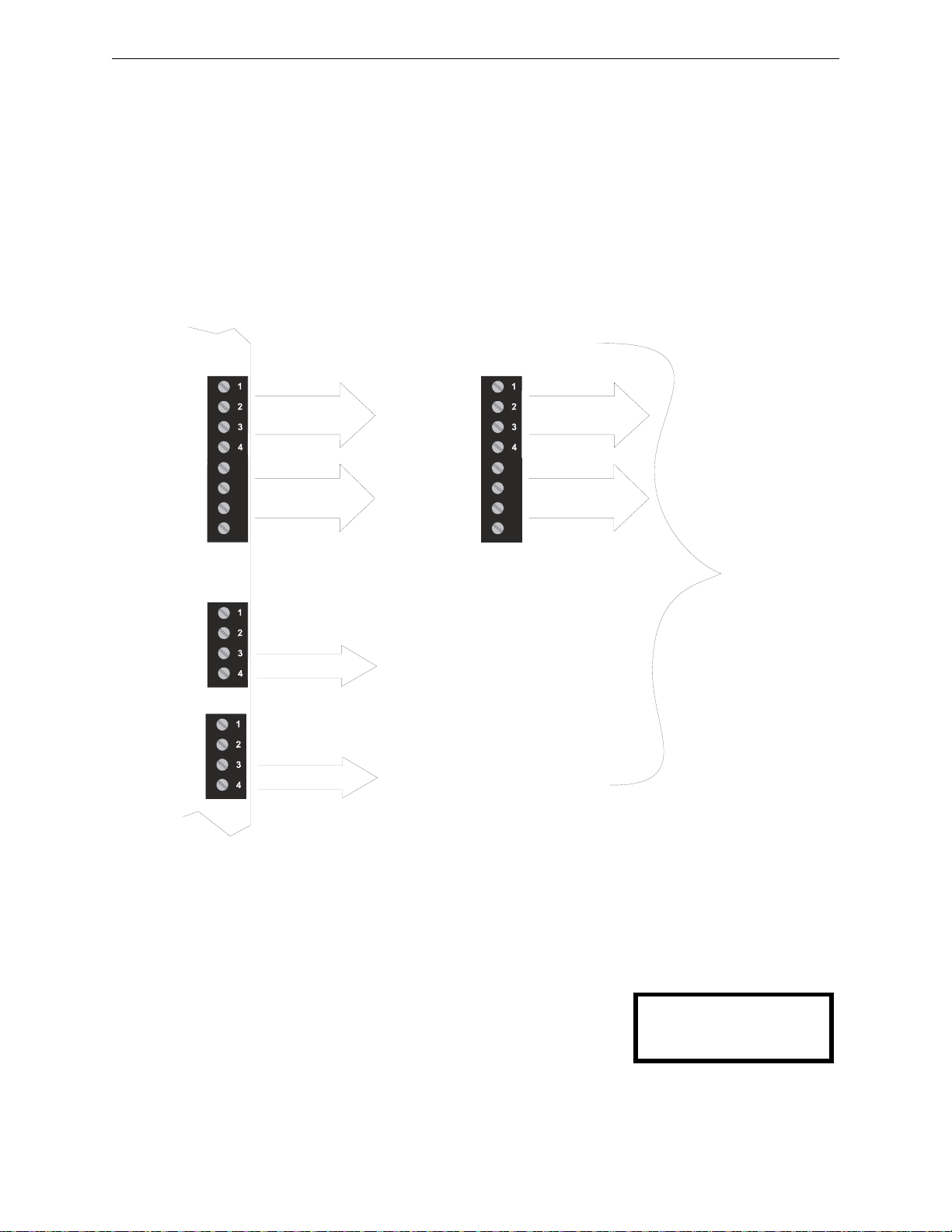
Two Programmable Relays and One Fixed Trouble Relay - TB5, TB6 & TB7
Contact rating: 2.0 amps @ 30 VDC (resistive), 0.5 amps @ 30 VAC (resistive)
Form-C relays, nonpower-limited, nonsupervised
Refer to Figure 2.5 on page 29 for information on power-limited relay circuit wiring
EIA-232 - TB3
EIA-232 PC applications connections: Terminal 5 (Receive), 6 (Transmit), 7 (DTR), 8 (Ground)
Power-limited, supervised
14 MS-9050 Series Manual — P/N 52413:G 4/14/2014
Page 15
Controls and Indicators Product Description
TB3
TB1 TB1
TB1
55
66
77
88
NAC #1
NAC #2
2.5 amps max
per circuit
2.5 amps max
per circuit
Alarm
2.5 amps max
per panel
Primary
ANN-BUS
Standby
1.0 amp max
per panel
0.5 amp max
per circuit
ANN-SEC
Option Card
0.5 amp max
per circuit
Figure 1.1 Current Availability
powerdis9050.wmf
Refer to the battery calculations section for additional information.
Nonresettable/
Resettable Power
#1
#2
1.0 amp max
per circuit
1.0 amp max
per circuit
OR
SYSTEM ALL NORMAL
10:00A 092105
Special Application Primary ANN-BUS Power - TB3
Nominal Operating Voltage: 24 VDC
Maximum Current (Terminals 1 & 2): 500 mA
Power-limited, supervised
Special Application Secondary ANN-BUS Power - ANN-SEC - TB1
Nominal Operating Voltage: 24 VDC
Maximum Current (Terminals 1 & 2): 500 mA
Power-limited, supervised
The following figure illustrates the maximum current that is possible for each major panel output
circuit and the total current available from the FACP.
1.3 Controls and Indicators
LCD Display
The FACP uses an 80-character (4 lines X 20 characters) high
viewing angle LCD display. The display includes a long life
LED backlight that remains illuminated. If AC power is lost
and the system is not in alarm, the LED backlight will turn off
to conserve batteries.
LED Indicators
LED indicators are provided to annunciate the following conditions:
MS-9050 Series Manual — P/N 52413:G 4/14/2014 15
Page 16

Product Description Circuits
Figure 1.2 Membrane/Display Panel
9050udkypd.cdr
• AC Power (green)
• Fire Alarm (red)
• Supervisory (yellow)
• Trouble (yellow)
• Alarm Silenced signals (yellow)
Key Panel
Mounted on the main circuit board, the key panel includes a window for the LCD display and LED
indicators as listed above. The key panel, which is visible with the cabinet door closed, has 25
keys, including a 16 key alpha-numeric pad similar to a telephone keypad.
Function keys:
• Acknowledge/Step
• Alarm Silenced
• Drill (Manual Evacuate)
• Reset (lamp test)
Service/program keys:
• Keys labeled 1 to 9
• * key
• # key
• 0 (recall) key
• 1st Event key
• Clear key
• Escape key
• Mode key
• Four cursor keys (up, down, left and right)
• Enter key
Local Piezo Sounder
A piezo sounder provides separate and distinct pulse rates for alarm, trouble and supervisory conditions.
1.4 Circuits
SLC Communication Loop
One SLC loop is provided on the FACP main circuit board. The SLC loop, configurable for NFPA
Style 4, 6 or 7, provides communication to addressable detectors, monitor (initiating device) and
control (output device) modules. Refer to the SLC Wiring manual for information on wiring
devices.
Output Circuits
The following output circuits are available on the FACP:
• Charger - 24 VDC Battery Charger (up to 18 AH batteries)
• NAC (Notification Appliance Circuits) - Two NACs configurable for Style Y (Class B) or
Style Z (Class A), are provided with various programmable features.
16 MS-9050 Series Manual — P/N 52413:G 4/14/2014
Page 17

Digital Alarm Communicator/Transmitter Product Description
Relays
One fixed and two fully programmable Form-C dry contact relays are provided. The fixed fail-safe
relay monitors system trouble and the two programmable relays are factory default programmed for
system alarm and system supervisory. Contacts are rated 2.0 amps @ 30 VDC (resistive) and 0.5
amps @ 30 VAC (resistive). The programmable relays can be programmed for the following operations:
• fire alarm
• silenceable alarm
• trouble
• supervisory
• supervisory auto-resettable
• DACT communication failure
• process monitor
• process monitor auto-resettable
• hazard alert
• medical alert
•AC loss
1.5 Digital Alarm Communicator/Transmitter
T wo modular phone jacks allow easy connection to telephone lines. Modular jacks are labeled PH1
for Primary Phone Line and PH2 for Secondary Phone Line. Two telephone line active red LEDs
are provided as well as a green Kissoff LED. The integral digital communicator provides the following functions:
• Line Seizure: takes control of the phone lines disconnecting any premises phones
• Off/On Hook: performs on and off-hook status to the phone lines
• Dialing the Central Station(s) number: default is Touch-Tone
• For tone burst or touchtone type formats: discern proper Ack and Kissoff tone(s). The
frequency and time duration of the tone(s) varies with the transmission format. The control
panel will adjust accordingly.
• Communicate in the following formats:
12 Tone Burst types: 20 pps
(3+1, 4+1, 4+2, 3+1 Exp., 4+1 Exp., 4+2 Exp.)
3 Touchtone Types
4+1 Ademco Express
4+2 Ademco Express
Ademco Contact ID
1.6 Components
Main Circuit Board
®
, programmable to rotary
The main circuit board contains the system’s CPU, power supply, other primary components and
wiring interface connectors. The 4XTMF option module plugs in and is mounted to the main circuit board. The circuit board is delivered mounted to a chassis in the MS-9050UD backbox (refer
to circuit board illustration on page 10).
MS-9050 Series Manual — P/N 52413:G 4/14/2014 17
Page 18

Product Description Components
MS_9050UD.wmf
Battery Cable P/N 75203
9200batt.cdr
Cabinet
The MS-9050UD backbox provides space for two batteries (up to 18 Amp
Hour). Ample knockouts are provided for system wiring. Also available is
an optional dress panel, which mounts to the inside of the cabinet (required
by ULC for Canadian installations).
Batteries
The MS-9050UD cabinet provides space for two batteries (up to 18 Amp Hour). Batteries larger than 18
Amp Hour require an external charger such as the
CHG-75 or CHG-120F and a UL listed battery box
such as the BB-55F. Batteries must be ordered separately.
1.6.1 Intelligent Addressable Detectors: Newer Series
Intelligent, addressable detectors provide information to the control panel on an SLC Signaling
Line Circuit (refer to the SLC Wiring Manual for detailed information on addressable devices,
device installation, wiring and operation). This allows the control panel to continually process the
information to determine the status (alarm, trouble, maintenance or normal) of each detector . Each
detector responds to an SLC address that is set in the detector head using built-in rotary decimal
switches. Note that a blinking LED on an intelligent detector indicates communication between the
detector and the control panel. Refer to the Fire-Lite Device Compatibility Document for a list of
approved conventional detectors.
1.6.2 Intelligent Addressable Modules: Newer Series
The newer series of Control Modules and Monitor Modules provide an interface between the control panel and conventional notification and initiating devices. Each module can be set to respond
to an address with built-in rotary switches. A blinking LED on a monitor module indicates communication between the module and the control panel. These devices can also be used when
installed on older systems. Refer to the SLC Wiring Manual for information on addressable
devices. Refer to the Fire-Lite Device Compatibility Document for a list of approved conventional
notification and initiating devices.
1.6.3 300 Series Intelligent Addressable Devices
Fire-Lite’s 300 Series Intelligent Addressable Devices are fully compatible with the MS-9050UD
FACP. Refer to the SLC Wiring Manual for device information.
1.6.4 Device Accessories
End-of-Line Resistor Assembly
Refer to the SLC Wiring Manual for device information. The 47 K End-of-Line Resistor assembly (P/N: R-47K) is used to supervise the MMF-300, MDF-300, MMF-301 and CMF-300 module
circuits. The 3.9 K End-of-Line Resistor assembly is used to supervise the MMF-302 module
circuit. The End-of-Line resistors are included with each module.
Power Supervision Relay
18 MS-9050 Series Manual — P/N 52413:G 4/14/2014
The UL-listed End-of-Line power supervision relay is used to supervise the power to 4-wire smoke
detectors and notification appliances.
Page 19

Optional Modules and Accessories Product Description
EOL-C(R/W) Mounting Plate
The EOL-CR (red) and EOL-CW (white) are single End-of-Line resistor plates which are required
for use in Canada. An ELR, which is supplied with each module and fire alarm control panel, is
mounted to the EOL-C(R/W) plate. Resistors mounted to the plate can be used for the supervision
of a monitor and control module circuit.
1.7 Optional Modules and Accessories
The MS-9050UD main circuit board includes option module connectors for the following module:
4XTMF Transmitter Module
The 4XTMF provides a supervised output for local energy municipal box transmitter, alarm and
trouble reverse polarity. It includes a disable switch and disable trouble LED. A jumper on the
module is used to select an option which allows the reverse polarity circuit to open with a system
trouble condition if no alarm condition exists. The module plugs into connectors J8 and J9 which
are located near the top center of the main circuit board. When the 4XTMF module is installed,
Jumper JP28, on the main circuit board, must be cut to allow supervision of the module.
ANN-80 LCD Annunciator
The ANN-80 is a remote LCD annunciator which mimics the information displayed on the FACP
LCD display and provides remote RESET, SILENCE, ACKNOWLEDGE, and DRILL.
ANN-80C LCD Indicator (Canadian applications)
The ANN-80C is a remote LCD indicator which mimics the information displayed on the FACP
LCD display but does not allow remote control of the FACP.
ANN-LED Annunciator Module
The ANN-LED Annunciator Module provides three LEDs for each zone: Alarm, Trouble and
Supervisory. An ANN-LED module is installed in the dress panel for the Canadian version.
ANN-RLY Relay Module
The ANN-RLY Module, which can be mounted inside the cabinet, provides 10 Form-C relays.
ANN-S/PG Serial/Parallel Printer Gateway
The ANN-S/PG module provides a connection for a serial or parallel printer.
ANN-I/O LED Driver Module
The ANN-I/O module provides connections to a user supplied graphic annunciator.
ANN-SEC Secondary ANN-BUS Module
The ANN-SEC module provides another ANN-BUS port for more wiring flexibility and for Canadian applications requiring remote annunciation.
ANN-LC Lite-Connect Module
The ANN-LC provides a multi-FACP system where a single communicator and phone line for
Alarm, Trouble, and Supervisory reporting to a central station is shared using fiber-optic cables.
DP-51050 Dress Panel
A dress panel DP-51050 is available as an option. The dress panel restricts access to the system
wiring while allowing access to the membrane switch panel. The Canadian version is supplied
standard with a modified dress panel.
TR-CE Trim-ring
A trim-ring TR-CE is available as an option. The trim-ring allows semi-flush mounting of the cabinet.
MS-9050 Series Manual — P/N 52413:G 4/14/2014 19
Page 20

Product Description Optional Modules and Accessories
Battery Boxes
BB-26
The BB-26 battery box may be used to house up to two 26 AH batteries and the CHG-75 Battery
Charger. The battery box, which is red and is provided with knockouts, was designed specifically
to compliment mounting below the FACP.
BB-55F
The BB-55F battery box may be used to house two 26 AH bat teries, two 60 AH batteries or one
100 AH battery. When the CHG-120F is mounted in the BB-55F, two 26 AH or one 60 AH battery
may also be housed in the battery box.
PS-Tools Programming Utility
The PS-Tools Programming Utility can be used to locally or remotely program an MS-9050UD
directly from most IBM compatible personal computers (PC), running Windows
®
XP (or newer).
MS-9050UD program files can also be created and stored on the PC and then downloaded to the
control panel. The part number PK-CD Kit includes the Windows-based Programming Utility software on CD-ROM with online help file. A serial cable (P/N: PRT/PK-CABLE), which must be
purchased separately, is required for local connection of the PC to the RS-232 (PC/Printer) terminals at TB3 of the MS-9050UD main circuit board. Remote programming requires that the PC
have a 2400 baud (or faster) modem.
Important: Remote modification of FACP programming requires that the panel be enabled for
remote download (refer to “Remote Download” on page 150). Remote interrogation of panel pro gramming, history logs, detector status, etc., is possible without enabling the remote download
option.
Battery Chargers
CHG-75 Battery Charger
The CHG-75 is capable of charging up to 75 AH lead-acid batteries with the FACP. The FACP battery charger must be disabled, by removing jumper JP30, when using the CHG-75. The charger
and up to 26 AH batteries can be housed in the BB-26 battery box. Larger batteries and the charger
can be housed in the BB-55F battery box which can be mounted up to 20 feet away from the control
panel. Refer to the CHG-75 Manual for additional information.
CHG-120F Battery Charger
The CHG-120F is capable of charging up to 120 AH lead-acid batteries with the F ACP. The FACP
battery charger must be disabled, by removing jumper JP30, when using the CHG-120F. The batteries and charger can be housed in the BB-55F battery box which can be mounted up to 20 feet
away from the control panel. Note that when using the BB-55F for housing the charger and batteries greater than 26AH, multiple BB-55Fs are required. Refer to the CHG-120F Manual for addi-
tional information.
IPDACT, IPDACT-2, IPDACT-2UD - IP Communicator
The IPDACT, IPDACT-2, and IPDACT-2UD are a compact, Internet Protocol Communicators
designed to allow FACP status communication to a Central Station via the internet. No telephone
lines are required when using any IPDACT. Using Contact ID protocol from the FACP, any
IPDACT converts the standard DACT phone communication to a protocol that can be transmitted
and received via the internet. It also checks connectivity between the FACP and Central Station.
Refer to the IPDACT Series Product Installation Document P/N 53109 for additional information.
20 MS-9050 Series Manual — P/N 52413:G 4/14/2014
Page 21

Getting Started Product Description
1.8 Getting Started
The following is a brief summary of the minimal steps involved in bringing an MS-9050UD online:
• Install Backbox and Main Circuit Board (refer to “Mounting the Backbox” on page 24).
• Address and Install Intelligent Devices (refer to the SLC Wiring Manual).
• Enter Autoprogramming (refer to“Autoprogram” on page 58).
• Resolve Programming Conflicts.
• Go to Point Program to Enter Specific Data (refer to“Point Program” on page 59). Use the
right and left arrow keys to navigate between devices.
1.9 Telephone Requirements and Warnings
1.9.1 Telephone Circuitry
AC Ringer Equivalence Number (REN) = 03B
DC Ringer Equivalence Number (REN) = 0.0B
AC Impedance: 10.0 Mega Ohm
Complies with FCC Part 68
Mates with RJ31X Male Connector
Supervision Threshold: loss of phone line voltage for 2 minutes
The REN is used to determine the quantity of devices which may be connected to the telephone
line. Excessive RENs on the telephone line may result in the devices not ringing in response to an
incoming call. In most, but not all areas, the sum of the RENs should not exceed five (5.0). To be
certain of the number of devices that may be connected to the line as determined by the total RENs,
contact the telephone company to determine the maximum REN for the calling area.
1.9.2 Digital Communicator
Before connecting the control panel to the public switched telephone network, the installation of
two RJ31X jacks is necessary. If trouble is experienced with this equipment, for repair or warranty
information, please contact:
Manufacturer: Fire•Lite Alarms, Inc.
One Fire-Lite Place
Northford, CT 06472
(203) 484-7161
Product Model Number: MS-9050UD
FCC Registration Number: US:1W6AL03B9050UD
AC Ringer Equivalence: 0.3B
DC Ringer Equivalence: 0.0B
This equipment complies with Part 68 of the FCC rules and the requirements adopted by the ACTA.
On the inside of the FACP door is a label that contains, among other information, a product identifier in the format US:AAAEQ##TXXXX. If requested, this number must be provided to the telephone company.
Alarm dialing equipment must be able to seize the telephone line and place a call in an emergency
situation. It must be able to do this even if other equipment (telephone, answering system, computer modem, etc.) already has the telephone line in use. To do so, alarm dialing equipment must
be connected to a properly installed RJ31X jack that is electrically in series with and ahead of all
other equipment attached to the same telephone line. If there are any questions concerning these
MS-9050 Series Manual — P/N 52413:G 4/14/2014 21
Page 22

Product Description Telephone Requirements and Warnings
instructions, consult the telephone company or a qualified installer about installing the RJ31X jack
and alarm dialing equipment. Refer to“Digital Communicator” on page 32 for an illustration of
the proper installation of this equipment.
Important! The DACT must not
be used to dial a phone number that is call-forwarded.
1.9.3 Telephone Company Rights and Warnings
The telephone company, under certain circumstances, may temporarily discontinue services and/or
make changes in its facilities, services, equipment or procedures which may affect the operation of
this control panel. However, the telephone company is required to give advance notice of such
changes or interruptions.
If the control panel causes harm to the telephone network, the telephone company reserves the right
to temporarily discontinue service. Advance notification will be pro vid ed except in cases when
advance notice is not practical. In such cases, notification will be provided as soon as possible.
The opportunity will be given to correct any problems and to file a complaint with the FCC if you
believe it is necessary.
DO NOT CONNECT THIS PRODUCT TO COIN TELEPHONE, GROUND START, OR PARTY
LINE SERVICES.
When the control panel activates, premise phones will be disconnected.
Two separate phone lines are required. Do not connect both telephone interfaces to the same tele-
phone line.
The control panel must be connected to the public switched telephone network upstream (as first
device) of any private telephone system at the protected premises.
A plug and jack used to connect this equipment to the premises wiring and telephone network must
comply with the applicable FCC Part 68 rules and requirements adopted by ACTA. This equipment is designed to be connected to the telephone network or premises wiring using a compliant
RJ31X male modular plug and compatible modular jack that is also compliant.
1.9.4 For Canadian Applications
The following is excerpted from CP-01 Issue 5:
NOTICE: The Industry Canada (IC) label identifies certified equipment. This certification means
that the equipment meets certain telecommunications network protective, operational and safety
requirements as prescribed in the appropriate Terminal Equipment Technical Requirements document(s). The Department does not guarantee the equipment will operate to the users’s satisfaction.
Before installing this equipment, users should ensure that it is permissible to be connected to the
facilities of the local telecommunications company. The equipment must also be installed using an
acceptable method of connection. The customer should be aware that compliance with the above
conditions may not prevent degradation of service in some situations.
Repairs to certified equipment should be made by an authorized Canadian maintenance facility designated by the supplier. Any repairs or alterations made by the user to this equipment, or equipment malfunctions, may give the telecommunications company cause to request the user to
disconnect the equipment.
Users should ensure, for their own protection, that the electrical ground connections of the power
utility, telephone lines and internal metallic water pipe system, if present, are connected together.
This precaution may be particularly important in rural areas.
Users should not attempt to make such connections themselves, but should contact the appropriate
electric inspections authority, or electrician.
CAUTION
22 MS-9050 Series Manual — P/N 52413:G 4/14/2014
Page 23

Telephone Requirements and Warnings Product Description
“The Ringer Equivalence Number (REN) assigned to each terminal device provides an indication
of the maximum number of terminals allowed to be connected to a telephone interface. the termination of an interface may consist of any combination of devices subject only to the requirement
that the sum of the REN of all devices does not exceed 5.”
DOC Compliance - “This digital apparatus does not exceed the Class A limits for radio noise emissions from digital apparatus set out in the Radio Interference Regulations of the Canadian Department of Communications.”
Representative: NOTIFIER/FIRE•LITE, CANADA
10 Whitmore Road
Woodbridge, Ontario L4L 7Z4
Phone: (905) 856-8733
FAX: (905) 856-9687
IC Certificate Number: 2132A-9050UD
Ringer Equivalence Number (REN): 0.3B
MS-9050 Series Manual — P/N 52413:G 4/14/2014 23
Page 24
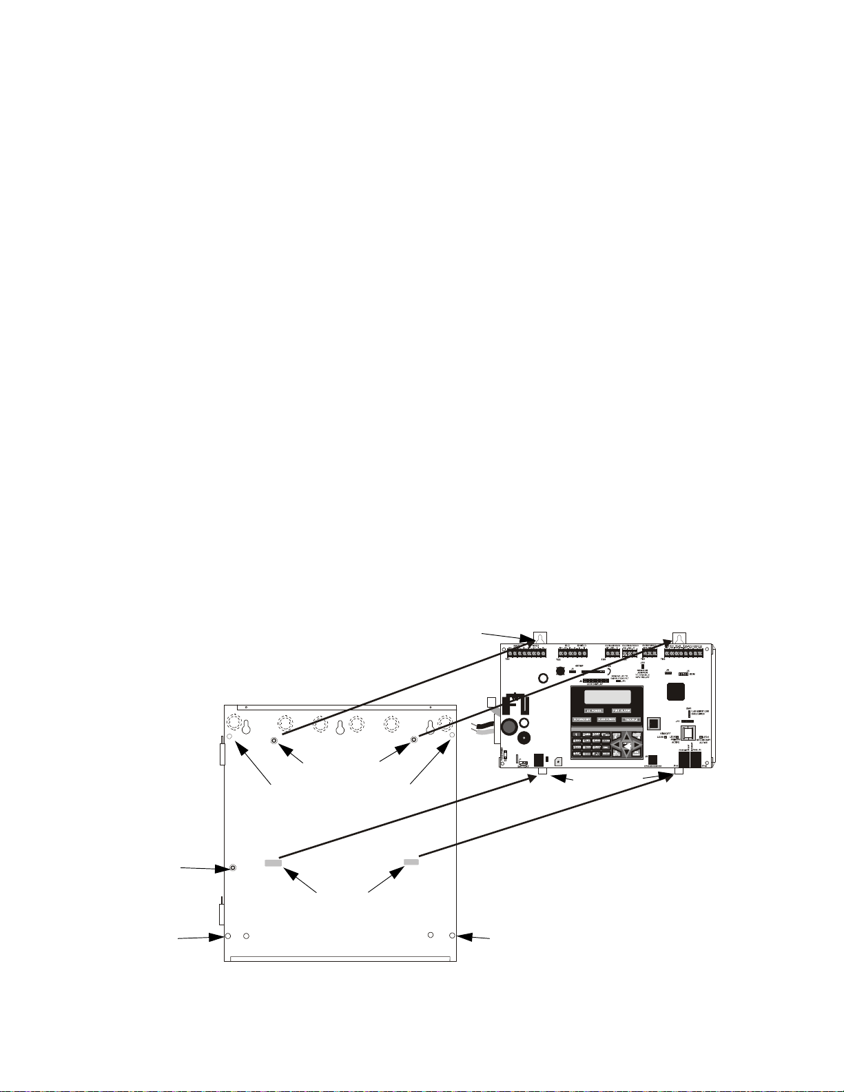
Section 2: Installation
Figure 2.1 Chassis Removal
Backbox
FACP Main Circuit Board on Chassis
mounting studs
9050udbdUnmn.cdr
mounting slots
mounting tabs
mounting tab holes
Ground Stud
backbox stud
mounting hole
backbox stud
mounting hole
backbox stud mounting holes
The cabinet may be either semi-flush or surface mounted. The cabinet mounts using two key slots
and two 0.250” (6.35 mm) diameter holes located in the backbox. The key slots are located at the
top of the backbox and the two securing holes at the bottom.
Carefully unpack the system and check for shipping damage. Mount the cabinet in a clean, dry,
vibration-free area where extreme temperatures are not encountered. The area should be readily
accessible with sufficient room to easily install and maintain the panel. Locate the top of the cabinet approximately 5 feet (1.5 m) above the floor with the hinge mounting on the left. Determine the
number of conductors required for the devices to be installed. Sufficient knockouts are provided
for wiring convenience. Select the appropriate knockout(s) and pull the conductors into the box.
All wiring should be in accordance with the National and/or Local codes for fire alarm systems.
2.1 Mounting the Backbox
The circuit board contains static-sensitive components. Always ground yourself with a proper
wrist strap before handling any boards so that static charges are removed from the body. Use static
suppressive packaging to protect electronic assemblies.
To prevent damage to the circuit board and to facilitate backbox mounting, the chassis with main
circuit board and transformer can be easily removed. Loosen the two 3/8” nuts securing the top
flanges of the chassis, then slide the chassis up to free it from the lower tabs. Place the chassis
assembly in a safe location until it can be reinstalled in the backbox.
Mark and predrill hole in the wall for the center top keyhole mounting bolt using the
dimensions illustrated in Figure 2.3 on page 26.
Install center top fastener in the wall with the screw head protruding.
Place backbox over the top screw, level, and secure.
Mark and drill the left and right upper and lower mounting holes.
Note: outer holes (closest to sidewall) are used for 16” O.C. stud mounting.
Install remaining fasteners and tighten.
24 MS-9050 Series Manual — P/N 52413:G 4/14/2014
Page 25
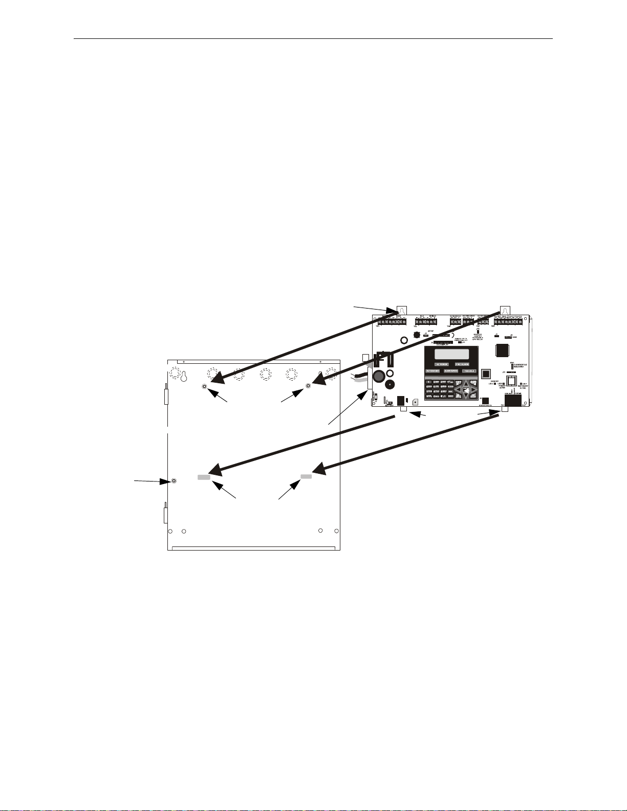
Mounting the Chassis/Transformer/Main Circuit Board Installation
Figure 2.2 Main Circuit Board/Chassis Installation
Backbox
FACP Main Circuit Board on Chassis
mounting studs
9050udbdmn.cdr
mounting slots
mounting tabs
mounting tab holes
Ground Stud
Transformer is mounted to the back
of the chassis in the lower left corner.
2.2 Mounting the Chassis/Transformer/Main Circuit Board
One transformer is supplied standard with the control panel. Install the transformer and chassis in
the location indicated in the following illustration.
1. When the location is dry and free of construction dust, install the chassis/transformer/circuit
board assembly.
2. Mount the chassis to the backbox by aligning the two mounting tabs with the slots in the
backbox, then position the two mounting hole tabs over the studs with nuts located in the upper
portion of the backbox.
3. Slide the tabs located on the bottom of the chassis into the mounting slots in the backbox by
pressing the chassis down.
4. Secure the chassis to the backbox by tightening the two mounting nuts (#10-32) at the top, and
to ensure proper grounding, use a 3/8” nut driver or socket.
5. If the main circuit board is not already attached to the chassis, install it by positioning the ten
mounting holes over the studs on the chassis and secure with the supplied screws.
6. Ensure the transformer plug is connected to Connector J2 on the FACP main circuit board
7. Complete the installation as detailed in the following sections.
MS-9050 Series Manual — P/N 52413:G 4/14/2014 25
Page 26
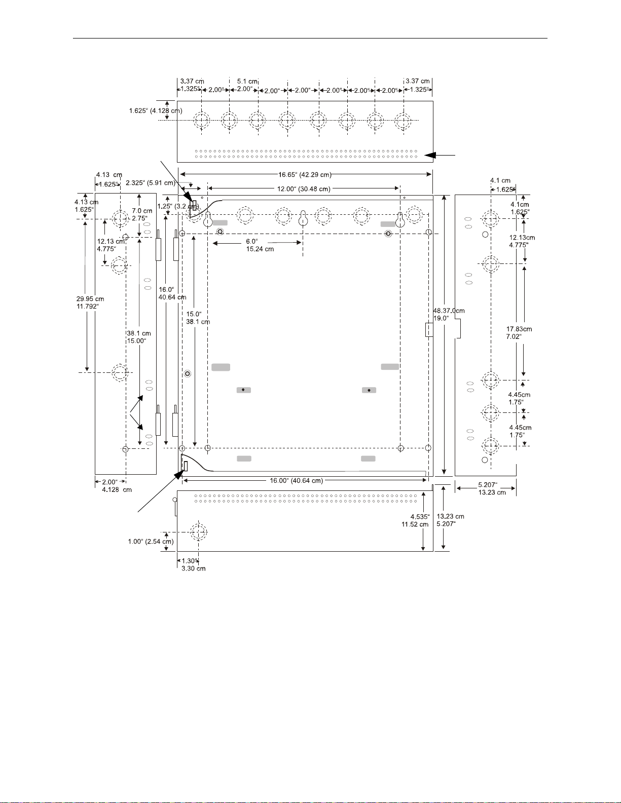
Installation Mounting the Chassis/Transformer/Main Circuit Board
Figure 2.3 FACP Cabinet Mounting
9050udencl.wmf
Semi-Flush Mounting
Do not recess box more
than 3.875” into wall to
avoid covering venting
holes on top of box.
Hinge Slot for
optional Dress Panel
Hinge Slot for
optional Dress Panel
Mounting
slots for
optional
Trim Ring
Semi-Flush
mounting hole
26 MS-9050 Series Manual — P/N 52413:G 4/14/2014
Page 27
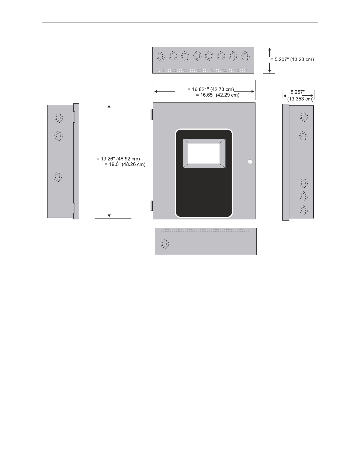
Mounting the Chassis/Transformer/Main Circuit Board Installation
Figure 2.4 FACP Cabinet Dimensions
9050udcab2.wmf
Left Side
Right Side
Bottom
Door
Door
Backbox
Backbox
Depth =
Depth
Top
MS-9050 Series Manual — P/N 52413:G 4/14/2014 27
Page 28

Installation Power
!
Interconnect
Cable
!
2.3 Power
WARNING: RISK OF DAMAGE AND ELECTRICAL SHOCK
SEVERAL DIFFERENT SOURCES OF POWER CAN BE CONNECTED TO THIS PANEL.
DISCONNECT ALL SOURCES OF POWER BEFORE SERVICING. THE PANEL AND
ASSOCIATED EQUIPMENT MAY BE DAMAGED BY REMOVING AND/OR INSERTING CARDS,
MODULES OR INTERCONNECTING CABLES WHILE THIS UNIT IS ENERGIZED.
2.3.1 AC Power and Earth Ground Connection
Primary power required for the MS-9050UD/C FACP is 120 VAC, 60 Hz, 3.0 amps or 240 VAC, 50
Hz, 1.5 amps for the MS-9050UDE. Overcurrent protection for this circuit must comply with Article 760 of the National Electrical Code (NEC) and/or local codes. Use 14 AWG (2.00 mm
larger wire with 600 volt insulation rating. Make certain that the AC main circuit breaker is off
before wiring any connections between the mains and the control panel. Connect wiring from the
AC mains to the Transformer on the FACP, being careful to observe proper connections.
Connect the AC ground wire to the Ground Stud located in the left side of the backbox. Refer to
Figure 2.2 on page 25 and the illustration below for location of the stud. If installing an optional
ANN-LC, ensure that the ground for the AC mains cable is installed first, closest to the backbox.
This connection is vital for maintaining the control panel’s immunity to unwanted transients generated by lightning and electrostatic discharge. Apply AC power to the panel only after the system is
completely installed and visually checked. Note that AC power must be applied to the panel before
installing the battery interconnect cable (refer to the following section).
2
) or
For AC connections to the MS-9050UDC, refer to“AC Power Connections for Canadian Applications” on page 184.
2.3.2 Battery Power
Before connecting the batteries to the FACP, make certain that
the interconnect cable between the batteries is not connected.
Do not connect the interconnect cable until the system is completely installed. Observe polarity when connecting the batteries. Connect the battery cable to J1 on the main circuit board.
Refer to“Power Supply Calculations” on page 153, for calculation of the correct battery rating.
WARNING: BATTERIES CONTAIN SULFURIC ACID
BATTERIES CONTAIN SULFURIC ACID WHICH CAN CAUSE SEVERE BURNS TO THE SKIN
AND EYES AND CAN DESTROY FABRICS. IF CONTACT IS MADE WITH SULFURIC ACID,
IMMEDIATELY FLUSH THE SKIN OR EYES WITH WATER FOR 15 MINUTES AND SEEK
IMMEDIATE MEDICAL ATTENTION.
28 MS-9050 Series Manual — P/N 52413:G 4/14/2014
Page 29
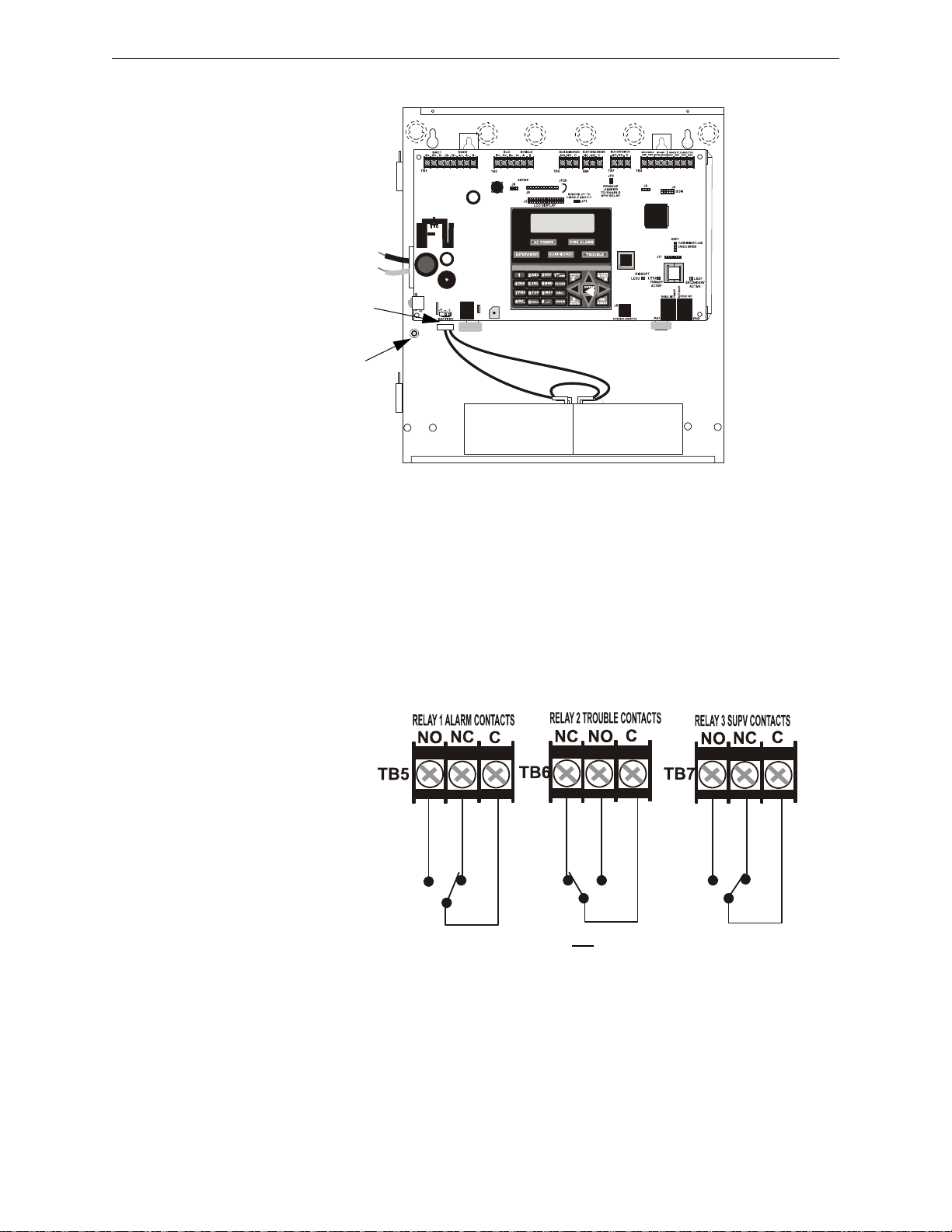
Relays Installation
AC Connection to
Transformer leads:
HOT
NEUTRAL
Battery Connection
to J1 on FACP
Ground Stud
9050udpowr.cdr
Figure 2.5 Relay Terminals
Relay contacts shown with power applied to panel
and no active troubles, alarms or supervisories
Note that the programmable relay
labeled as Relay 1 is factory default
programmed as Alarm and
programmable Relay 3 is factory default
programmed as Supervisory. The relay
labeled Relay 2 is fixed as a Trouble
relay and cannot be changed. It is a failsafe relay which will transfer on any
trouble or total power failure.
9050udrely.wmf
2.4 Relays
The FACP provides two programmable Form-C relays and one fixed fail-safe Form-C trouble
relay, all with contacts rated for 2.0 amps @ 30 VDC (resistive) or 0.5 amps @ 30 VAC (resistive).
Note that relay connections must be nonpower-limited. Refer to UL Power-limited wiring requirements.
MS-9050 Series Manual — P/N 52413:G 4/14/2014 29
Page 30
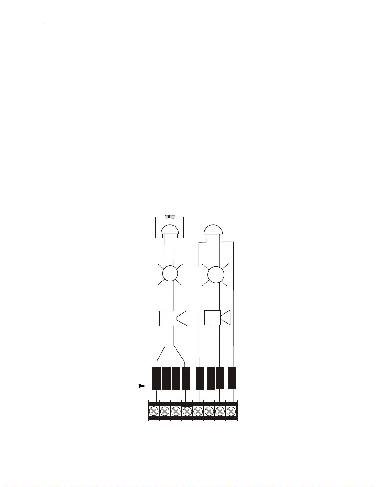
Installation Notification Appliance Circuits
TB1
B+ B- B-B+
A+ A-
A+
A-
NAC1
NAC2
-
+
B
+
B
-
1
4
A+A
-
23
+
+
B
+
B
-
A+A
-
+
+
+
5
6
7
8
Figure 2.6 NAC Wiring
Style Y (Class B) Notification Appliance
Circuits, supervised and power-limited -
4.7 K, ½ watt P/N:71252 UL listed
Polarized Bells
Polarized HornsPolarized Horns
Polarized Strobes
Notification Appliance Circuit
polarity shown in alarm state
Dummy Load all unused
circuits with a 4.7 K, ½ watt
resistor across the B+ & Bterminals or wire jumpers
between A+ & B+ and A- & B-.
9050udnac.wmf
Polarized Strobes
terminal number
NAC 1
NAC 2
Style Z (Class A) Notification Appliance
Circuits, supervised and power-limited
Polarized Bells
2.5 Notification Appliance Circuits
The control panel provides two NACs (Notification Appliance Circuits) Style Y (Class B) or Style
Z (Class A). Each circuit is capable of 2.5 amps of current. Total current in alarm for all external
devices cannot exceed 2.5 amps (refer to “Calculating the System Current Draw” on page 154).
Use UL listed 24 VDC notification appliances only. Circuits are supervised and power-limited.
Refer to the Fire-Lite Device Compatibility Document for a listing of compatible notification appliances. The NACs, which are located on the main circuit board, may be expanded via the Fire-Lite
FCPS Series field charger/power supplies.
NACs can also be configured for auxiliary power. If set for auxiliary power (door holder, resettable
power, non-resettable power) do not connect notification appliances. Refer to Section 1.2, “Specifications” for power capability.
The following sections describe the configuration and wiring of Style Y and Style Z Notification
Appliance Circuits on the FACP main circuit board.
2.5.1 Configuring NACs
The Notification Appliance Circuits are configured for Style Y (Class B) or Style Z (Class A) by
properly wiring the NAC devices to TB1 on the main circuit board as illustrated below.
30 MS-9050 Series Manual — P/N 52413:G 4/14/2014
Page 31

UL Power-limited Wiring Requirements Installation
TB1
J
1
Figure 2.7 Typical UL Power-limited Wiring Requirements
Power-limited Circuits (Class 2)
Power-limited
Circuits (Class 2)
Nonpower-limited Circuits (Class 1)
Nonpowerlimited, (Class 1)
supervised
Telephone
Circuit
AC Power
Hot
Neutral
Ground
9050udulpwr3.wmf
To Batteries
(nonpower-limited,
Class 1, supervised)
maintain minimum 0.25” between powerlimited and nonpower-limited circuits wiring
Ground Stud
Transformer
Wires
(nonpower-
limited,
supervised)
4XTMF
ANN-SEC
Power-limited
Circuits
(Class 2)
dashed lines
represent wiring
behind PCB
Power-limited
Circuits
(Class 2)
Nonpowerlimited,
supervised
Fiber Circuit
2.6 UL Power-limited Wiring Requirements
Power-limited and nonpower-limited circuit wiring must remain separated in the cabinet. All
power-limited circuit wiring must remain at least 0.25” (6.35 mm) away from any nonpower-limited circuit wiring and nonpower-limited circuit wiring must enter and exit the cabinet through different knockouts and/or conduits. If installing an optional ANN-LC, ensure that the ground for the
AC mains is installed first, closest to the backbox. A typical wiring diagram for the F ACP is shown
below.
MS-9050 Series Manual — P/N 52413:G 4/14/2014 31
Page 32

Installation Digital Communicator
Figure 2.8 DACT Installation
Customer Premises Equipment and Wiring
Telephone
Line
MS-9050UD
Network
Service
Provider’s
Facilities
Network
Demarcation
Point
RJ31X
Jack
Unused
RJ-11 Jack
Unused
RJ-11 Jack
Telephone
Telephone
Telephone
Answering
System
Fax Machine
Computer
9050ACTAdact.wmf
2.7 Digital Communicator
T wo independent telephone lines can be connected to the control panel. Telephone line control/command is made possible via double line seizure as well as usage of an RJ31X style interconnection. Note that it is critical that the panel's digital communicator be located as the first device
on the incoming telephone circuit to properly function.
Important! The DACT must not be used to dial a phone number that is call-forwarded per requirements of UL 864 9th Edition.
32 MS-9050 Series Manual — P/N 52413:G 4/14/2014
Page 33

Optional Modules/Accessories Installation Installation
!
Figure 2.9 Wiring Phone Jacks
9050udjack2.wmf
KISSOFF
PRIMARY
ACTIVE
SECONDARY
ACTIVE
PHONE LINEPHONE LINE
P
R
I
M
A
R
Y
SECONDARY
Modular Female
Connectors
Male Plug
Connectors
Secondary
Phone Line
PH-2
Primary
Phone Line
PH-1
7 foot cable
MCBL-7
(ordered
separately)
Note: Shorting bars
inside RJ31X Jack
removed during male
plug insertion.
RJ31X Jack
RJ31X Jack
Ring
Ring
Tip
Tip
Tip
Ring
Tip
Ring
Green Wire
Red Wire
To premise phones
Green Wire
Red Wire
To premise phones
(Primary Lines)
Incoming Telco
Phone Lines
(Secondary Lines)
Incoming Telco
Phone Lines
The control panel's digital communicator is built into the main circuit board. Connection and wiring of two phone lines is required as shown below.
2.8 Optional Modules/Accessories Installation
WARNING: RISK OF ELECTRIC SHOCK
DISCONNECT ALL SOURCES OF POWER (AC AND DC) BEFORE INSTALLING OR REMOVING
ANY MODULES OR WIRING.
2.8.1 4XTMF Transmitter Module Installation
The 4XTMF provides a supervised output for a local energy municipal box transmitter in addition
to alarm and trouble reverse polarity. A jumper option allows the reverse polarity circuit to open
with a system trouble condition if no alarm condition exists. A disable switch allows disabling of
the transmitter output during testing to prevent accidental calling of the monitoring service.
Local Energy Municipal Box Service (NFPA 72 Auxiliary Fire Alarm Systems):
Supervisory Current: 5.0 mA
Trip Current: 350 mA (subtracted from notification appliance power)
Coil Voltage: 3.65 VDC
Maximum Coil Resistance: 14.6 ohms
Maximum allowable wire resistance between panel and trip coil: 3 ohms
Municipal Box wiring can leave the building
Remote Station Service (NFPA 72 Remote Station Fire Alarm Systems) - Intended for connection to a polarity reversal circuit or a Remote Station receiving unit having compatible ratings:
MS-9050 Series Manual — P/N 52413:G 4/14/2014 33
Page 34
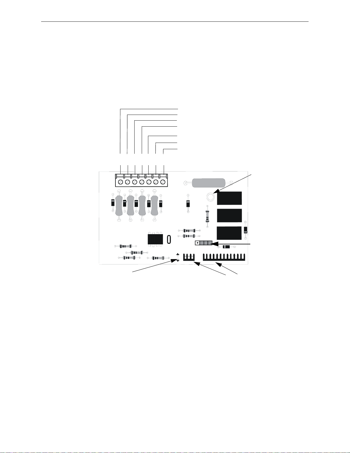
Installation Optional Modules/Accessories Installation
Figure 2.10 4XTMF Transmitter Module
Connect to FACP at J8 & J9
Disconnect Switch
shown in disconnect
position
TBL Jumper
}Remote Alarm (power-limited)*
}Remote Trouble (power-limited)*
No connection
}Municipal Box (nonpower-limited)*
1 2 3 4 5 6 7
+ - + - + -
Polarities are shown for module activation
Note: 4XTMF Module is not directly suitable for transmitting reverse polarity supervisory signal. For an
application using reverse polarity of a supervisory signal, refer to “FACP with Keltron” on page 170.
* Wiring from these
terminals can exit the
protected premises.
Dummy load terminals 6
and 7 (4.7K, ¼ watt
resistor) if Municipal Box
is not connected.
Disconnect LED
4xtmfl.wmf
Maximum load for each circuit: 10 mA
Reverse polarity output voltage: 24 VDC
Remote Alarm and Remote Trouble wiring can leave the building
Before installing the module, place the disconnect switch to the right (disconnect) position to prevent accidental activation of the municipal box. Note that a Disconnect LED will illuminate after
the module is installed in the MS-9050UD. In addition, the System Trouble LED will turn on to
indicate the Disconnect condition.
The following steps must be followed when installing the 4XTMF module:
1. Remove all power (Primary and Secondary) from the FACP before installing 4XTMF.
2. Cut jumper JP28 on the main circuit board to allow the control panel to superv ise the 4XTMF
module.
3. Remove two screws securing main circuit board to mounting plate and install two standoffs for
securing 4XTMF module to main circuit board. Refer to Figure 2.11 for standoff locations on
main circuit board.
4. Carefully plug the connectors on the 4XTMF module into connectors J8 and J9 on the MS-
9050UD main circuit board, being careful not to bend any pins.
5. Secure 4XTMF module to standoffs with supplied screws removed in step 3.
6. Reapply power to the FACP.
7. For proper 4XTMF operation, the main circuit board output relays must be programmed for
the factory default settings: Alarm Relay 1, Trouble Relay 2, and Supervisory Relay 3.
34 MS-9050 Series Manual — P/N 52413:G 4/14/2014
Page 35

Optional Modules/Accessories Installation Installation
Figure 2.11 4XTMF Connectors to MS-9050UD Connectors
J8 & J9 Connectors
Jumper JP2
Standoff
Standoff
4XTMF
MS-9050UD
9050ud4xtm.wmf
Jumper JP28
8. When the installation has been completed, enable the 4XTMF module by sliding the
disconnect switch to the left.
9. Test system for proper operation.
NOTE: Jumper JP2 on the FACP main circuit board can be used to configure the FACP
supervisory relay for operation with the 4XTMF module. Relay 3 at TB3 must be programmed as
a supervisory relay.
Removing the jumper from JP2 will allow the 4XTMF to generate a trouble if the supervisory
contact opens
Leaving the jumper on JP2 will prevent generation of a trouble if the supervisory contact opens
2.8.2 ANN-SEC Option Card
The ANN-SEC option card allows for a secondary ANN-BUS. Install the ANN-SEC as follows.
1. Remove the chassis mounting screw to the right of TB7 and replace it with the supplied 0.5” x
4-40 male-female standoff.
2. Install the header into J13 on the main circuit board.
MS-9050 Series Manual — P/N 52413:G 4/14/2014 35
Page 36

Installation ANN-BUS Devices
J13
T
B
1
J
1
ANN-SEC
FACP Circuit Board
connector to J13 on
main circuit board
standoff and screw
Figure 2.12 Installing the ANN-SEC Option Card
9050annsec.wmf
!
3. Secure the ANN-SEC to the circuit board with the supplied screw.
2.9 ANN-BUS Devices
r
WARNING: RISK OF ELECTRICAL SHOCK
DISCONNECT ALL SOURCES OF POWER (AC AND DC) BEFORE INSTALLING OR REMOVING
ANY MODULES OR WIRING.
Guidelines
• A variety of optional annunciation devices can be connected to an ANN-BUS communication
circuit. ANN Series devices can be connected to the primary communication circuit (EIA-485)
terminals on TB3. A secondary communication circuit (EIA-485) for these devices is available
at TB1 on the ANN-SEC card.
• When using one ANN-BUS circuit, up to eight (8) annunciators can be supported.
• When using both ANN-BUS communication circuits, the primary circuit supports up to three
(3) annunciators and the secondary circuit supports up to (5) annunciators.
Compatible devices include:
– ANN-80 LCD Annunciator
– ANN-80C LCD Indicator (Canadian Applications)
– ANN-S/PG Serial/Parallel Printer Interface Module
– ANN-I/O LED Driver Module
– ANN-LED Annunciator Module
– ANN-RLED Annunciator Module (red alarm LEDs only)
– ANN-RLY Relay Module
– ANN-LC Lite-Connect Module
• When operating two ANN-BUS circuits, only one ANN-S/PG Printer module can be used in
the system.
• The panel is capable of operating a primary ANN-BUS (TB3) and a secondary ANN-BUS
(TB1 on ANN-SEC card) simultaneously.
2.9.1 ANN-BUS Wiring
This section contains information on calculating ANN-BUS wire distances and the types of wiring
36 MS-9050 Series Manual — P/N 52413:G 4/14/2014
configurations (Class B).
Page 37

ANN-BUS Devices Installation
Calculating Wiring Distance for ANN-BUS Modules
The following instructions will guide the installer in determining the type of wire and the maximum
wiring distance that can be used with FACP ANN-BUS accessory modules.
T o calculate the wire gauge that must be used to connect ANN-BUS modules to the FACP, it is necessary to calculate the total worst case current draw for all modules on a single 4-conductor bus.
The total worst case current draw is calculated by adding the individual worst case currents for each
module. The individual worst case values are shown in the following table:
ANN-80(C) LCD Annunciator/Indicator 0.040 amps
ANN-S/PG Serial/Parallel Printer Interface Module 0.040 amps
ANN-I/O LED Driver Module 0.200 amps
ANN-RLY Relay Module 0.075 amps
ANN-(R)LED Annunciator Module 0.068 amps
ANN-LC Lite-Connect Module 0.150 amps
1 Total worst case current draw on a single ANN-BUS cannot exceed 0.5 amp.
If current draw exceeds 0.5 amps, refer to “Powering ANN-BUS Devices from
Auxiliary Power Supply” on page 39.
After calculating the total worst case current draw, Table 2.1 specifies the maximum distance the
modules can be located from the FACP on a single wire run. The table ensures 6.0 volts of line
drop maximum. In general, the wire length is limited by resistance, but for heavier wire gauges,
capacitance is the limiting factor. These cases are marked in the chart with an asterisk (*). Maximum length can never be more than 6,000 feet (1,800 m), regardless of gauge used. The formula
used to generate this chart is shown in the note below.
Total Worst Case Current
Draw (amps)
0.100 1,852 ft. 4,688 ft. * 6,000 ft. *6,000 ft.
0.200 926 ft. 2,344 ft. 3,731 ft. 5,906 ft.
0.300 617 ft. 1,563 ft. 2,488 ft. 3,937 ft.
0.400 463 ft. 1,172 ft. 1,866 ft. 2,953 ft.
0.500 370 ft. 938 ft. 1,493 ft. 2,362 ft.
Model Number
Wiring Distance: ANN-BUS Modules to FACP
22 Gauge 18 Gauge 16 Gauge 14 Gauge
Worst Case Current Draw
1
Table 2.1 Wiring Distances
The following formulas were used to generate the wire distance chart:
Maximum Resistance (Ohms) =
Maximum Wire Length (feet)
(6,000 feet maximum)
where: Rpu = Ohms per 1,000 feet for various Wire Gauges (see table below)
Total Worst Case Current Draw (amps)
=
Maximum Resistance (Ohms)
MS-9050 Series Manual — P/N 52413:G 4/14/2014 37
6.0 Volts
Rpu
*500
Page 38

Installation ANN-BUS Devices
Wire Gauge Ohms per 1,000 feet (Rpu)
22 16.2
18 6.4
16 4.02
14 2.54
Exception: When using the ANN-RLY module, the installer must ensure that the maximum
24VDC power line drop does not exceed 0.3 volts. This results in the following wiring limitations:
Wire Gauge Maximum Wire Length
18 312 feet
16 497 feet
14 787 feet
12 1,250 feet
Wiring Distance Calculation Example:
Suppose a system is configured with the following ANN-BUS modules:
• 3 ANN-80 Remote Fire Annunciators
• 1 ANN-S/PG Serial/Parallel Printer Interface Module
• 1 ANN-I/O LED Driver Module
The total worst case current is calculated as follows:
ANN-80 Current Draw = 3 X 0.040 amps = 0.120 amps
ANN-S/PG Current Draw = 1 X.0.040 amps = 0.040 amps
ANN-I/O Current Draw = 1 X.0.200 amps = 0.200 amps
Total Worst Case Current Draw = 0.360 amps
Using this value and referring to the Wiring Distance Table 2.1 on page 37, it can be found that the
available options are:
463 feet maximum using 22 Gauge wire
1,172 feet maximum using 18 Gauge wire
1,866 feet maximum using 16 Gauge wire
2,953 feet maximum using 14 Gauge wire
38 MS-9050 Series Manual — P/N 52413:G 4/14/2014
Page 39

ANN-BUS Devices Installation
Figure 2.13 FACP wiring to ANN-BUS Device
ANN-BUS Device
MS-9050UD
ANN-BUS and power wiring are
supervised and power-limited
Primary ANN-BUS
Figure 2.14 Powering ANN-BUS Devices from FCPS-24FS6/8
ANN-80
MS-9050UD
FCPS-24FS6/8
-24 VDC
+24 VDC
ANN-BUS
Cut Ground Fault Detection jumper JP1 (FACP monitors for ground faults)
ANN-BUS and power wiring are
supervised and power-limited
ann80tofcps.wmf
Wiring Configuration
Figure 2.13 illustrates the wiring between the FACP and ANN-BUS devices.
Powering ANN-BUS Devices from Auxiliary Power Supply
Figure 2.14 illustrates the powering of ANN-BUS devices from an auxiliary power supply such as
the FCPS-24FS6/8, when the maximum number of ANN-BUS devices exceeds the ANN-BUS
power requirements.
MS-9050 Series Manual — P/N 52413:G 4/14/2014 39
Page 40

Installation ANN-BUS Devices
2.9.2 ANN-BUS Device Addressing
Each ANN-BUS device requires a unique address (ID Number) in order to communicate with the
F ACP. A 5-position DIP switch on each device is used to set this address. The address set for these
devices must also be programmed at the FACP for the specific device (refer to the programming
section titled “ANN-BUS” on page 96).
A maximum of 8 devices can be connected to the FACP ANN-BUS communication circuit. Device
addresses do not need to be sequential and can be set to any number between 01 and 08. Note that
00 is not a valid address. The following table shows the DIP switch setting for each address.
When installed and enabled through FACP programming, the ANN-LC will always be set to
address 08. No dip switch settings are used to set the address on the ANN-LC.
NOTE: Address (ID Number) DIP switches on some devices may have more than 5 switch
positions. Unless otherwise specified in the documentation supplied with each device, switch
positions 6 and above must be set to OFF.
Address
not valid OFF OFF OFF OFF OFF
01 OFF OFF OFF OFF ON
02 OFF OFF OFF ON OFF
03 OFF OFF OFF ON ON
04 OFF OFF ON OFF OFF
05 OFF OFF ON OFF ON
06 OFF OFF ON ON OFF
07 OFF OFF ON ON ON
08 OFF ON OFF OFF OFF
Switch 5
1
Switch 4 Switch 3 Switch 2 Switch 1
1 Switch 5 must be set to OFF for ANN-BUS devices to be recognized.
2.9.3 ANN-80(C) Remote Fire Annunciator/Indicator
The ANN-80(C) Annunciator/Indicator is a compact, 80 character, backlit LCD remote fire annunciator which mimics the FACP display. It also provides system status indicators for AC Power,
Alarm, Trouble, Supervisory and Alarm Silenced conditions. The ANN-80 Annunciator provides a
button for Reset, Silence, Acknowledge, and Drill. The ANN-80C does not provide these buttons.
Communication between the ANN-80(C) and FACP is accomplished over a two wire serial interface employing the ANN-BUS communication format. The devices are powered, via two additional wires, from either the host FACP or remote UL-listed, filtered, power supply.
Specifications
• Operating Voltage Range: 18 VDC to 28 VDC
• Current Consumption @ 24 VDC nominal (filtered and nonresettable):
Normal/Standby (no activity): 37.0 mA
Trouble: 39.0 mA
Alarm: 40.0 mA
AC Fail ( not backlit): 15.0 mA
• For use indoors in a dry location
40 MS-9050 Series Manual — P/N 52413:G 4/14/2014
Page 41

ANN-BUS Devices Installation
Key switch shown in
OFF/Locked position
Press in latch
and
Pull annunciator
cover open
Annunciator cover
with LCD display
Annunciator backplate
ann-80_iso.wmf
aann80kitmount.wmf
Annunciator mounted on
surface wedge from the
ANN-SB80KIT
Annunciator mounted on stacked
surface wedge and backbox from
the ANN-SB80KIT
Annunciator mounted on
surface backbox from the
ANN-SB80KIT
Installation
Ensure that all power (AC and DC) has been removed from the F ACP before installing the annunciator.
Opening/Closing Annunciator
The following procedure details the steps used to open the annunciator in order to access the terminal block and DIP switches (refer to figure below):
1. Turn the key switch to the ON (Unlocked) position by turning the key counter-clockwise
2. Push in the snap latch located on the right side of the unit while pulling the cover open
3. To close the cover, make certain the key switch is in the ON (Unlocked) position. Swing the
cover closed, snapping it shut
4. Turn the key switch to the OFF (Locked) position by turning clockwise and remove the key
Mounting
The ANN-80 can be surface or semi-flush mounted to a single, double or 4” square electrical box.
Select and remove the appropriate knockout(s), pull the necessary wires through the knockouts and
mount the annunciator in or on the wall depending on the type of installation desired.
The ANN-SB80KIT(-R/-W) is an available mounting kit for the ANN-80 annunciator. The kit
comes with a surface backbox and surface wedge for angled viewing. The two pieces can be used
separately or can be stacked together.
The ANN-80 cover must be attached to the annunciator backplate before mounting the annunciator
to the electrical box/wall. The cover cannot be reattached or removed after the annunciator has been
mounted.
MS-9050 Series Manual — P/N 52413:G 4/14/2014 41
Page 42

Installation ANN-BUS Devices
wiring channel
wires
TB1
Wiring ANN-80 to FACP
The following steps can be used as a guide to wire the annunciator. Make certain all power has
been removed from the FACP prior to annunciator installation.
1. Route wires from hole in backplate, through wiring channel and then to ANN-80 terminal
block TB1.
2. Remove appropriate amount of wire insulation.
3. Connect the wiring from the FACP ANN-BUS to annunciator TB1 terminals 3 (A) & 4 (B).
Make certain to connect A to A and B to B.
4. If appropriate, connect the wiring going to the next device on the ANN-BUS to TB1 terminals
3 & 4. Make certain to connect A to A and B to B.
5. Connect the wiring from the 24 VDC power source to annunciator TB1 terminals 1 (-) & 2 (+).
Make certain to observe proper polarity.
6. If appropriate, connect the power wiring going to the next device to terminals
1 (-) & 2 (+). Make certain to observe proper polarity.
7. After all connections are made, remove extra wire from inside of annunciator by dressing it
neatly through wire channel, with any excess wire pushed back through hole into electrical
box.
42 MS-9050 Series Manual — P/N 52413:G 4/14/2014
Page 43

ANN-BUS Devices Installation
Figure 2.15 ANN-80 Wiring to FACP
FACP
ANN-80
ANN-BUS and power wiring are
supervised and power-limited
Primary ANN-BUS
The following table shows the ANN-80 connections to the MS-9050UD.
MS-9050UD (TB3) ANN-80 (TB1)
Terminal 1 GND (-) Terminal 1 (-)
Terminal 2 PWR (+) Terminal 2 (+)
Terminal 3 A (ANN-BUS) Terminal 3 (A)
Terminal 4 B (ANN-BUS) Terminal 4 (B)
Programming
Following installation and wiring of the ANN-80 LCD annunciator to the FACP, the annunciator
must be added to the system via FACP programming. Refer to the programming section titled
“ANN-BUS” on page 96 in this manual for detailed programming information. Select the LCD
option for programming.
Trouble Response
If the ANN-80 is installed but the ANN-BUS is not enabled at the FACP, the ANN-80 will indicate
a trouble condition by NOT turning on its AC Power indicator. The LCD will also display Key Bus
Trouble and the piezo will sound approximately once every 10 seconds. Note that the FACP will
provide no indication of an ANN-80 trouble.
T o clear the ANN-80 trouble condition, enable the ANN-BUS and program the address corresponding to the address set on the ANN-80 at the FACP.
2.9.4 ANN-S/PG Serial/Parallel Interface Module
MS-9050 Series Manual — P/N 52413:G 4/14/2014 43
The ANN-S/PG Serial/Parallel Interface module allows the connection of a serial or parallel printer
to the FACP for a real-time log of system events, detector status reports and event history. The
module is provided with a plastic enclosure for surface mounting. Proceed with the installation as
described in the following:
1. Ensure that all power (AC and DC) has been removed from the FACP.
Page 44

Installation ANN-BUS Devices
Figure 2.16 ANN-S/PG Connection to FACP
ANN-S/PG Module
MS-9050UD
Cable
Connectors
for connection
to printer
Parallel
Serial
ANN-BUS and power wiring are
supervised and power-limited
annspgto9050ud.wmf
Primary
ANN-BUS
2. Connect the ANN-S/PG to the FACP as illustrated in Figure 2.16.
3. Using the DIP switches on the back of the ANN-S/PG module, assign an ID number (address)
to the module.
4. Select the address and configuration options for the ANN-S/PG module as described in the
Programming section of this manual (refer to “ANN-BUS” on page 96).
Note that the Auto-configure feature allows the programmer to quickly bring all instal led
ANN-BUS modules online (refer to “Auto-Configure” on page 104).
5. Connect a printer to the ANN-S/PG Parallel or Serial connectors (refer to Figure 2.16). Only
one printer can be connected.
Specifications
• Operating Voltage: 24 VDC
• Current (Alarm and Standby): 45 mA
• Ambient Temperature: 32
o
F to 120oF (0oC to 49oC)
• Max. Wiring Distance from FACP: 6,000 ft. (1,800 m)
• Mounting: Surface
• Dimensions: 6”W x 7-3/4”H x 1-7/16”D (15.2 cm W x 19.7 cm H x 3.7 cm D)
• For indoor use in a dry location only
PRN-6F Printer Installation
When connected to the FACP via the ANN-S/PG module, the PRN prints the status changes within
the control panel and time-stamps the printout with the time of day and date that the event occurred.
It provides 80 columns of data on standard 9” x 11” tractor-feed paper. This section contains information on connecting a printer to the control panel and setting the printer options.
Connecting PRN-6F Printer
Remote printers require a primary AC power source. If required for the fire alarm system configuration (for example, a Proprietary Fire Alarm System), a remote printer requires a secondary power
source (battery backup). Since a secondary power source is not provided as a standard feature, a
separate UL-listed Uninterruptible Power Supply (UPS) should be used. The building emergency
power supply may be used, as long as it meets the power continuity requirements of NFPA 72.
Refer to NFPA 72 f or further details.
Connect the remote printer to the FACP via the ANN-S/PG module using a standard DB-25 cable.
One end of the cable will plug into the DB-25 connector on the PRN printer and the other end plugs
into the parallel connector on the ANN-S/PG module. Note that the 9-pin DB-9 port on the ANNS/PG is used to connect a serial printer. The 25-pin port is used for a Centronics parallel printer
cable. Connect either a serial or parallel printer, but not both at the same time.
44 MS-9050 Series Manual — P/N 52413:G 4/14/2014
Page 45

ANN-BUS Devices Installation
Setting Printer Options
Refer to the documentation supplied with the PRN-6F printer for instructions on using the printer
menu controls. Set the printer options (under the menu area) as shown in the following table:
Option Setting Option Setting
Font HS Draft CPI 10CPI
LPI 6 LPI Skip 0.5
ESC Character ESC Emulate Epson FX-850
Bidirectional Copy ON I/O
CG-TAB Graphic Buffer 40K
Country E-US ASCII Serial
Auto CR OFF Baud 9600 or 2400
Color Option Not Installed Format 7 Bit, Even, 1 Stop
Formien Protocol XON/XOFF
Lines 6LPI=60 Character Set Standard
Standard Exec 10.5 SI.Zero On
Auto LF On
PAPER
BIN 1 12/72”
BIN 2 12/72”
SINGLE 12/72”
PUSH TRA 12/72”
PULL TRA 12/72”
PAP ROLL 12/72”
Table 2.2 PRN Setup Options
2.9.5 ANN-I/O LED Driver Module
The ANN-I/O is an LED driver module that can be used in a wide variety of applications, including
as an interface with most customized graphic annunciators. The ANN-I/O can drive up to 40
LEDs. The module is provided with a plastic enclosure for mounting inside the annunciator or
accessory box. The following sections describe hardware installation. Refer to the section
titled“ANN-BUS” on page 96 for programming information.
MS-9050 Series Manual — P/N 52413:G 4/14/2014 45
Page 46

Installation ANN-BUS Devices
Figure 2.17 ANN-I/O Board Layout
ANN-BUS (ID#)
Address DIP
switch
ANN-BUS Connector
Terminals not used (future)
ann-IObrd.cdr
ANN-I/O Board Layout
Figure 2.17 illustrates the ANN-I/ O bo ard showing locations of screw terminals for connection to
the FACP, pin connectors for connecting LEDs and the DIP switch for selecting the ANN-BUS ID
number.
Specifications
46 MS-9050 Series Manual — P/N 52413:G 4/14/2014
• Max. ANN-BUS Voltage: 28 VDC
• Max. Current:
Alarm: 200 mA
Standby: 35 mA
Each LED: 10 mA
• Operating Temperature: 32
• For indoor use in a dry location only
o
F to 120oF (0oC to 49oC)
Page 47

ANN-BUS Devices Installation
Figure 2.18 ANN-I/O Connection to FACP
ANN-I/O Module
MS-9050UD
ANN-BUS and power wiring are
supervised and power-limited
ann-IOtoFACP.wmf
Primary ANN-BUS
ANN-I/O Connection to FACP
The ANN-I/O connects to the FACP via the ANN-BUS as illustrated in Figure 2.18. After the
ANN-I/O is connected to the panel, it must be added to the system via FACP programming. Refer
to the section titled “Modules Installed” on page 96.
ANN-I/O Module LED Wiring
There are four 12-pin connectors on the ANN-I/O module for connecting LEDs. Each set of 10
LEDs get their power from Pin 11 of the corresponding connector. Internal resistors are sized so
that there is approximately 10 mA of current for each LED. No series resistors are required. LED
outputs can be mapped to output circuits. Refer to the programming section titled “Modules
Installed” on page 96 of this manual.
MS-9050 Series Manual — P/N 52413:G 4/14/2014 47
Page 48

Installation ANN-BUS Devices
Figure 2.19 ANN-I/O LED Wiring
ann-IOleds.wmf
The LEDs are wired as illustrated in Figure 2.19. Note that the illustration depicts only connectors
P1 and P2. Wiring is identical for P3 (LEDs 21-30) and P4 (LEDs 31-40).
48 MS-9050 Series Manual — P/N 52413:G 4/14/2014
Page 49

ANN-BUS Devices Installation
Figure 2.20 ANN-LEDs (shown in possible stacked configuration)
ann-ledstacked.wmf
Figure 2.21 Exploded View of ANN-LED
ann-led.wmf
2.9.6 ANN-LED Annunciator Module
The ANN-LED and ANN-RLED annunciator modules provide LED annunciation of general system faults and input zones/points when used with a compatible FACP. The ANN-LED module provides alarm (red), trouble (yellow) and supervisory (yellow) indication for up to ten input zones or
addressable points. The ANN-RLED provides alarm (red) indication for up to 30 input zones or
addressable points. Multiple ANN-(R)LED modules may be used for full sy stem coverage.
Specifications
• Max. ANN-BUS Voltage: 24 VDC
• Max. Current:
Alarm: 68 mA
Standby: 28 mA
• Operating Temperature: 32
o
F to 120o F (0o C to 49o C)
• For indoor use in a dry location only
Mounting and Installation
The ANN-LED Module is supplied with a metal backbox, mounting bracket, and cover. Refer to
the ANN-LED Installation Document #53032 for more information.
MS-9050 Series Manual — P/N 52413:G 4/14/2014 49
Page 50

Installation ANN-BUS Devices
Figure 2.22 ANN-LED Connection to FACP
ANN-LED
+24 VDC
-24 VDC
ANN-BUS and power wiring are
supervised and power-limited
MS-9050UD
Primary ANN-BUS
Ground wire from mounting screw to
FACP Earth Ground stud is required
for some Canadian applications.
(Refer to “ANN-LED Annunciator
Installation for Canadian
Applications” on page 181).
ANN-BUS (ID#)
Address DIP switch
annledto9050ud.wmf
ANN-LED Board Layout and Connection to FACP
Figure 2.22 illustrates the ANN-LED board showing locations of screw terminals for connection to
the FACP and the DIP switches for selecting the ANN-BUS ID number.
2.9.7 ANN-RLY Relay Module
The ANN-RLY relay module provides 10 programmable Form-C relays when used with a compatible FACP.
Specifications
• Operating Voltage: 24 VDC
• Max. Current:
Alarm: 75 mA
Standby: 15 mA
• Operating Temperature: 32
• For indoor use in a dry location only
o
F to 120o F (0o C to 49o C)
50 MS-9050 Series Manual — P/N 52413:G 4/14/2014
Page 51

ANN-BUS Devices Installation
mounting holes
mounting hooks through
mounting slots
grounding wire
ANN-RLY
ANN-MBRLY
mounting bracket
mounting holes
mounting holes
FACP Backbox Installation
using ANN-MBRLY mounting bracket
FACP Chassis Installation
mounting holes
mounting holes
ANN-RLY on ANNMBRLY mounting
bracket
ROME Series Installation
using ANN-MBRLY mounting bracket
Figure 2.23 ANN-RLY Mounting Options
ann-rlyinchassis.wmf
ann_mbriyincab3.wmf
rome-relay-plate3.wmf
Mounting and Installation
The ANN-RLY relay module can be mounted inside the FACP main circuit board chassis or inside
the ROME Series enclosure. Refer to the ANN-RLY Installation Document #53033 for instructions
on chassis mounting or to the ROME Series Installation Document #53530 for mounting in the separate backbox.
MS-9050 Series Manual — P/N 52413:G 4/14/2014 51
Page 52
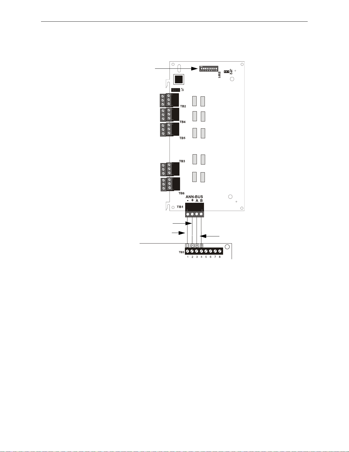
Installation ANN-BUS Devices
Figure 2.24 ANN-RLY Connection to FACP
FACP
ANN-RLY
Primary ANN-BUS
+24 VDC
-24 VDC
ANN-BUS and power wiring are
supervised and power-limited
ANN-BUS (ID#)
Address DIP switch
ANN-RLY Board Layout and Connection to FACP
Figure 2.24 illustrates the ANN-RLY board showing locations of screw terminals for connection to
the FACP and the DIP switches for selecting the ANN-BUS ID number.
2.9.8 ANN-LC Lite-Connect Module
Specifications
• Operating Voltage: 24 VDC
• Max. Current: 150 mA
• Operating Temperature: 32°F to 120°F (0°C to 49°C)
• For indoor use in a dry location only
Installation
Ensure that all power (AC and DC) has been removed from the FACP before installing the
ANN-LC.
Mounting
The ANN-LC mounts inside the FACP cabinet. Slide the two tabs of the bracket into the backbox
protrusions on the lower right side. Secure with the included self-tapping screw. Refer to the
ANN-LC Product Installation Document for more information.
52 MS-9050 Series Manual — P/N 52413:G 4/14/2014
Page 53

ANN-BUS Devices Installation
ANN-LC
backbox
protrusions
Figure 2.25 Mounting the ANN-LC into the Backbox
FLLCmnttabs.wmf
!
J13
J13
J3
MS-9050UD
ANN-LC
Figure 2.26 Wiring the ANN-LC Directly to the MS-9050UD
9050toFLLC.wmf
Do not
Use
Observe proper alignment!
(Red stripe on cable)
!
Wiring the ANN-LC to the MS-9050UD
Without an ANN-SEC Card
The ANN-LC connects from the MS-9050UD via ribbon cable. Using the 21” ribbon cable,
connect the MS-9050UD at J13 to J3 on the ANN-LC. Run the ribbon cable up behind the
MS-9050UD board.
WARNING: OBSERVE PROPER ALIGNMENT (RED STRIPE ON CABLE)
CONNECTING MISMATCHED PINS WILL CAUSE PERMANENT DAMAGE TO THE BOARD.
WHEN ATTACHING THE RIBBON CABLE, BE SURE IT DOES NOT GET OVERLY TWISTED.
CAUTION: DO NOT CONNECT DOWNSTREAM DEVICES
WHEN USING THE RIBBON CABLE TO DIRECTLY CONNECT THE ANN-LC TO THE MS-9050UD,
DO NOT CONNECT ANY ANN-BUS DEVICES DOWNSTREAM FROM THE ANN-LC.
MS-9050 Series Manual — P/N 52413:G 4/14/2014 53
Page 54

Installation ANN-BUS Devices
J13
T
B
1
J
1
ANN-SEC
B A+ -
+ - B A
to ANN-BUS
devices
downstream
MS-9050UD
ANN-LC
TB1
TB2
TB1
Figure 2.27 Wiring the ANN-LC to the MS-9050UD Via the ANN-SEC Card
9050sectoFLLC.wmf
powerlimited,
supervised
power-
limited,
supervised
Note: Figure 2.27 is just a
graphical representation for
terminal wiring purposes only.
Actual wiring from the ANN-SEC
to the ANN-LC should be run
behind the board, between the
board and chassis. Maintain at
least 0.25” (6.35 mm) spacing
between power-limited and
nonpower-limited circuit wiring.
With an ANN-SEC Card
Connect the ANN-SEC as shown in Section 2.8.2. Connect TB1 on the ANN-SEC to TB1 on the
ANN-LC as shown below. Additional secondary ANN-BUS devices can be connected to TB2 on
the ANN-LC.
Programming
Following installation and wiring of the ANN-LC module to the FACP, the module must be added
to the system via F ACP programming. Select the LCD option for system programming. Refer to the
programming section titled “Lite-Connect” on page 91 in this manual for detailed programming
information.
54 MS-9050 Series Manual — P/N 52413:G 4/14/2014
Page 55

Section 3: Programming
NOTICE TO USERS, INSTALLERS, AUTHORITIES HAVING JURISDICTION AND OTHER INVOLVED PARTIES
This product incorporates field-programmable software. In order for the product to comply with the requirements in the Standard for
Control Units and Accessories for Fire Alarm Systems, UL 864, certain programming features or options must be limited to specific
values or not used at all as indicated below:
Program feature
or option
Trouble Call Limit N
Remote Download Y
3.1 Programming Data Entry
Permitted in
UL 864? (Y/N)
Possible settings
Refer to “Trouble Call Limit (Dialer Runaway Prevention)” on
page 107.
Trouble Call Limit = 0 (factory default): unlimited calling to
Central Station for any trouble condition
Trouble Call Limit = 1 - 99: limits call for each unique trouble
to from 1 to 99 within a 24 hour period
Refer to “Remote Download” on page 150.
Remote Download - Proprietary No
Remote Download - Proprietary Yes
Settings permitted in UL
864
Trouble Call Limit = 0
for unlimited Central Station
trouble calls
Remote Download
Proprietary Yes for
Proprietary Installations Only
Programming can be accomplished using the MS-9050UD keypad or by connecting an optional
standard computer keyboard. The keyboard can be connected to the PS-2 connector J6 on the control panel main circuit board.
The information presented in this section refers to programming the MS-9050UD via the onboard
keypad. If an optional computer keyboard is connected to the MS-9050UD main circuit board, the
following table describes the keyboard keys which correspond to the onboard keypad keys.
Keypad Keys Computer Keyboard Keys
1st Event Home
CLR Delete
ESC Esc
RECALL Insert
**
##
A - Z A - Z
0 - 9 0 - 9
(on QZ key) Space bar
——
//
••
ENTER Enter
ACK/STEP F1
SILENCE F2
DRILL F3
RESET F4
MS-9050 Series Manual — P/N 52413:G 4/14/2014 55
Page 56

Programming User Programming
SYSTEM ALL NORMAL
10:00A 012110
1=READ STATUS MODE
2=PROGRAMMING MODE
3=MANUAL DIAL MODE
4=REMOTE DOWNLOAD
3.2 User Programming
The MS-9050UD is completely field programmable and requires no special software skills. While
programming the MS-9050UD, the fire pro tection capabilities of the control panel are
Site-specific programming may be accomplished in three ways:
• Autoprogramming Feature - This is a convenient method for quickly bringing the FACP
addressable SLC devices on-line without the necessity of programming each device
individually. Refer to “Autoprogram” on page 58 for a detailed description of
Autoprogramming
• Manual programming or editing, using the FACP keypad or a PC keyboard
• Off-line Programming and Editing Feature - allows creation and editing of site-specific custom
programs using a Windows-based computer. For programs requiring a large amount of data
entry, this method may be preferred. A PK-CD programming kit can be ordered for this
purpose
The System All Normal screen will be displayed in a programmed system with no active alarms,
troubles or supervisories, as illustrated below:
enabled.
Read Status and Manual Dial mode can be entered while the panel is in any
mode of operation.
Manual Dial mode, however, cannot be entered while the panel is communicating with the Central
Station. If an alarm or supervisory event exists at the panel, the event must be cleared before entering Programming mode. To access any of the programming or read status features, the Enter or
Mode key must be pressed, which will cause the LCD to display the following:
Pressing 1, while this screen is being displayed, will cause the control panel to enter the Read Status Mode which allows the user to view the programmed features and status of the control panel
The Read Status feature is not password protected. Refer to“Read Status” on page 136 for a
detailed description of this feature.
Pressing 2 will select user Programming Mode which may only be accomplished by an authorized
person. After pressing 2, a screen will prompt for a password. After entering the correct password,
the user may select from a list of programming options.
Pressing 3 will select the Manual Dial Mode which allows the user to enter a troubleshoot mode of
operation.
Pressing 4 will select Remote Download which allows the user to enable the remote programming
option. Refer to“Remote Download” on page 150.
Exit Programming, Read Status, and Manual Dial Mode
The programmer can exit any mode by repeatedly pressing the keypad ESC (Escape) key until the
display reads System All Normal. Note that the data which is entered during Programming mode
saved until the programmer exits this mode by repeatedly pr essing the ‘ESC’ key. If the Reset
is not
key is pressed or power is lost before exiting Programming mode, all data just entered will be lost.
User Programming Levels
There are two user programming levels:
• User Master Program Level 1 is used for programming panel specific data relating to device
types, zoning, messages, control panel functions, etc.
56 MS-9050 Series Manual — P/N 52413:G 4/14/2014
Page 57

Initial Power-up Programming
TROUBL IN SYSTEM
NO DEVICES INSTALLED
09:03A 012110
1=READ STATUS MODE
2=PROGRAMMING MODE
3=MANUAL DIAL MODE
4=REMOTE DOWNLOAD
• User Maintenance Program Level 2 is used by a qualified operator to access features such as
Disable/Enable, View and Clear History, Walktest and System Time Change.
3.3 Initial Power-up
The following sections describe the initial programming procedures for a new system. The same
procedures are used to modify programming in an existing system.
After completing the wiring of addressable devices to the SLC, apply power to the control panel. If
the addressable devices have not yet been programmed into the F ACP, their LEDs will not flash and
the following trouble message will be displayed.
3.4 Programming Screens Description
Four options are available when the Enter key is pressed: Read Status, Programming, Manual Dial
Mode and Remote Download. The Read Status and Programming options have multiple functions
or features which may be chosen. To view all of the choices, it is necessary that the programmer
scroll through a number of additional subscreens. These selections are displayed on multiple
screens to make them more readable for the programmer. Refer to “Master Programming Level”
on page 58, for additional information on the various screens.
The title of the main option screen will always be displayed at the top of the subscreens for the programmer’s convenience. If additional subscreens exist, an Up or Down arrow will be displayed in
the upper right corner of the screen being viewed. The programmer can then press the keypad Up
or Down arrow key to view the new subscreen. To select one of the choices in a screen, the programmer presses the keypad numerical key corresponding to the desired choice.
Note that subscreens may also have multiple options which require viewing more than one screen.
The same process, as detailed in the previous paragraphs, is follo wed to view all option choices.
3.5 Programming and Passwords
There are two factory set programming passwords which will access the Programming screens as
indicated in the following examples. From either of the screens, access to specific system and
device features or programming may be obtained. All user programming entries are stored in nonvolatile memory . The factory set passwords can be changed by the user as described in “Password
Change” on page 118. If an invalid password is entered, the blinking cursor will return to the first
password character position. To exit Programming, Read Status, Manual Dial mode or Remote
Download at any time, press the ESC (Escape) key repeatedly. Note that Programming mode must
be exited using the ESC key in order to store the program data entered during this mode. If the
Reset key is pressed or power is lost before exiting Programming mode, the data just entered will
not be saved.
T o access user Programming mode, press the Enter or Mode key. The LCD will display the follow-
ing:
MS-9050 Series Manual — P/N 52413:G 4/14/2014 57
Page 58

Programming Master Programming Level
PROGRAMMING
ENTER PASSWORD
QQQQQ
PROGRAMMING
1=AUTOPROGRAM
2=POINT PROGRAM
3=ZONE SETUP
PROGRAMMING
1=POINT PROGRAM
2=HISTORY
3=PROGRAM CHECK
PROGRAMMING
1=AUTOPROGRAM
2=POINT PROGRAM
3=ZONE SETUP
Programming Screen #1
PROGRAMMING
1=LOOP SETUP
2=SYSTEM SETUP
3=VERIFY LOOP
PROGRAMMING
1=HISTORY
2=WALKTEST
3=OPTION MODULES
PROGRAMMING
1=PASSWORD CHANGE
2=CLEAR PROGRAM
3=PROGRAM CHECK
Programming Screen #2
Programming Screen #3
Programming Screen #4
PROGRAMMING
1=AUTOPROGRAM
2=POINT PROGRAM
3=ZONE SETUP
Programming Screen #1
To enter the user Programming mode, press 2. The display will read as follows:
Entering the Master
If the Maintenance
level password (default 00000) will cause the following screen to appear:
level password (default 11111) is entered, the following screen will appear:
Note that in the two preceding screens, an arrow appears to inform the programmer that additional
options can be viewed by pressing the keypad down arrow key.
3.6 Master Programming Level
When the Master Program Level password is entered, the control panel will enter user Programming mode. In this mode, the piezo sounder remains off, the trouble relay is activated and the system Trouble LED flashes until Programming mode is exited. The following display will appear:
The down arrow which appears in the display indicates that additional programming choices can be
viewed by pressing the down arrow key on the keypad. If a down and up arrow appear in the display, pressing the ‘down’ arrow key will display the subsequent Programming Screens as illustrated
below while pressing the ‘up’ arrow key will display the previous screen.
3.6.1 Autoprogram
Pressing 1 while viewing Programming Screen #1, will select the Autoprogram option, which
prompts the control panel to poll all devices installed on the SLC loop. The primary purpose of
autoprogramming is to allow the installer a fast and easy way to bring the system on-line as quickly
as possible. The first time the system is powered-up, it should be autoprogrammed.
If the system is already programmed and Autoprogram is initiated, the system will only add default
values for newly installed devices.
58 MS-9050 Series Manual — P/N 52413:G 4/14/2014
Page 59

Master Programming Level Programming
AUTOPROGRAM
AUTOPROGRAMMING!
PLEASE WAIT
Autoprogram Progress Screen
# OF DET LOOP1 022
# OF MON LOOP1 015
# OF CON LOOP1 010
Autoprogram Result Screen #1
PROGRAMMING
1=AUTOPROGRAM
2=POINT PROGRAM
3=ZONE SETUP
Programming Screen #1
POINT PROGRAM
SELECT TYPE
1=DETECTOR
2=MODULE
Point Program Screen
DETECTOR
1=ADD
2=DELETE
3=EDIT
Detector Screen
ADD DETECTOR
ENTER DETECTOR#
QQQ
Add Detector Screen
When Autoprogram is selected, the control panel will begin autoprogramming the system by communicating with each addressable device installed on the SLC loop. While autoprogramming, the
panel will display the following:
When Autoprogramming is completed, the control panel will display the type and quantity of each
device installed on the SLC loop similar to the following display:
In the preceding example, the display indicates that the SLC Loop has 22 addressable detectors, 15
monitor modules and 10 control modules installed.
Pressing the ESC key will return the display to Programming Screen #1.
3.6.2 Point Program
The Point Program option allows the programmer to add a new addressable device to an SLC loop,
delete an existing device from a loop or change the programming for an existing device. Pressing
2, while viewing Programming Screen #1, will select the Point Program option and display the following screen:
Detector Programming
Pressing 1, while viewing the Point Program Screen, will allow the programmer to add, delete or
change the programming of an addressable detector. The following screen will be displayed by the
control panel:
Add Detector
Pressing 1 while viewing the Detector Screen will display the following screen which allows the
programmer to add a new detector address to programming:
MS-9050 Series Manual — P/N 52413:G 4/14/2014 59
A flashing cursor will appear in the position of the first asterisk to the left. The programmer keys in
the three digit detector address, such as 005.
Page 60

Programming Master Programming Level
DETECTOR TYPE
1=SMOKE(PHOTO)
2=USER-DEFINED-1
3=SMOKE(ION)
ADD DETECTOR
DETECTOR# 005
IS ADDED
DETECTOR
1=ADD
2=DELETE
3=EDIT
Detector Screen
DELETE DETECTOR
ENTER DETECTOR#
QQQ
Delete Detector Screen
DELETE DETECTOR
DETECTOR# 005
IS DELETED
EDIT DETECTOR
ENTER POINT ADDRESS
QQQ
Edit Detector Screen
NO DETECTOR
INSTALLED
Edit Detector Screen #1
When the last digit is keyed-in, the following screen will be displayed:
Press the down arrow key to view additional choices. Press the number corresponding to the
desired selection to program that type to the newly added detector.
When the type has been selected, the following screen will be displayed:
The programmer can continue adding detectors by pressing the ESC key which will return the display to the Add Detector Screen.
Delete Detector
Pressing 2 in the Detector Screen will display the Delete Detector Screen which allows the programmer to delete a specific detector:
A flashing cursor will appear in the position of the first asterisk to the left. The programmer keys in
the three digit detector address, such as 005. When the last digit is keyed-in, the following screen
will be displayed:
The programmer can continue deleting detectors by pressing the ESC key which will return the display to the Delete Detector Screen.
Edit Detector
The programmer can change a detector’s existing or factory default programming by pressing 3 in
the Detector Screen. The following screen will be displayed:
A flashing cursor will appear in the position of the first asterisk to the left. The programmer keys in
the three digit detector address, such as 017.
When the last digit is keyed-in, if the selected address has not been added to programming, a screen
showing information about a device that is
installed with a lower address, closest to the selected
address, will be displayed.
If no
detectors have been installed on the loop, the following will be displayed:
60 MS-9050 Series Manual — P/N 52413:G 4/14/2014
Page 61

Master Programming Level Programming
TROUBL SMOKE(PHOTO)
<ADJ><NOUN>
ZNNN
Q 1D017
Edit Detector Screen #1
NORMAL SMOKE (PHOTO)
<ADJ><NOUN>
ZNNN
V 1D017
Edit Detector Screen #1
EDIT DETECTOR 1D017
1=ENABLED YES
2=TYPE SMOKE(PHOTO)
3=VERIFICATION OFF
Edit Detector Screen #2
EDIT DETECTOR 1D017
1=WALKTEST NO
2=PAS NO
3=PRE-SIGNAL NO
Edit Detector Screen #3
EDIT DETECTOR 1D017
1=ZONE ASSIGNMENT
00 QQ QQ QQ QQ
Edit Detector Screen #4
Edit Detector Screen #5
EDIT DETECTOR 1D017
1=ADJECTIVE/NOUN
2=DESCRIPTION
QQQQQQQQQQQQQQQQQQQQ
EDIT DETECTOR
1=ENABLED
2=TYPE
3=VERIFICATION
Edit Detector Screen #2
If the selected address has been added to programming, device summary screens will be displayed.
These screens allow the programmer to view all device settings at a single glance. Pressing the left
or right arrow keys will allow the programmer to rapidly view the devices at the previous or next
address (if installed).
If a detector (such as a photoelectric detector) with the selected address is not physically installed
on the SLC or has a communication fault but the address is programmed in the system, the following screen will be displayed:
If the selected address has been added to programming and a detector (such as a photoelectric
detector) with the selected address is physically installed on the SLC and is communicating with
the control panel, the following will be displayed:
To change the programming for the displayed detector, press the keyboard ‘down’ arrow key to
view the Edit Detector screens.
In the preceding example:
Normal - indicates that the detector with the selected address is physically installed on the
SLC and communicating with the control panel (enabled)
<ADJ><NOUN> - represents the adjective and noun, which have been programmed,
describing the location of the displayed device
ZNNN - represents the first of five possible software zones that the detector is assigned to
(NNN = the three digit zone number from 000 - 019)
V or * - indicates whether or not alarm verification is enabled (V = alarm verification
enabled and * = alarm verification disabled)
1D017 - represents the Loop, Device type and Device address (1 = SLC Loop, D=Detector
and 017 = Detector Address 017)
The following examples show the editing of a photoelectric smoke detector with address 017,
located on the SLC loop:
MS-9050 Series Manual — P/N 52413:G 4/14/2014 61
Enable/Disable Detector
T o Enable or Disable the detector , press the 1 key while viewing the Edit Detector Screen #2. Each
press of the key will toggle the screen between Enabled Yes and Enabled No. If Enabled No is
selected, the detector will not be polled by the control panel, preventing the detector from reporting
alarms and troubles to the panel. The control panel will display the device type and address which
has been disabled and will turn on the Trouble LED.
Page 62

Programming Master Programming Level
EDIT DETECTOR
1=ENABLED
2=TYPE
3=VERIFICATION
Edit Detector Screen #2
DETECTOR TYPE
1=SMOKE(PHOTO)
2=USER-DEFINED-1
3=SMOKE (ION)
Detector Type Screen #1
EDIT DETECTOR
1=WALKTEST
2=PAS
3=PRE-SIGNAL
Edit Detector Screen #3
Type
To select the type of detector being programmed, press the 2 key while viewing the Edit Detector
Screen #2. This will cause the control panel to display the following Detector Type Screen:
Pressing the down arrow key will display additional detector types as indicated in the following
table.
Detector Type Action When Activated
Smoke Photo Fire Alarm
User-Defined-1 same as previous (Smoke Photo)
Smoke Ion Fire Alarm
User-Defined-2 same as previous (Smoke Ion)
Heat Detect Fire Alarm
User-Defined-3 same as previous (Heat Detect)
Smoke DuctP Fire Alarm
User-Defined-4 same as previous (Smoke DuctP)
Photo w/Heat Fire Alarm
User-Defined-5 same as previous (Photo w/Heat)
Duct Superv Supervisory, latching
User-Defined-6 same as previous (Duct Superv)
Photo Superv Supervisory, latching
User-Defined-7 same as previous (Photo Super)
future not used
While viewing any Detector Type screen, select the type of detector being programmed by pressing
the corresponding keyboard number key. The display will return to Edit Detector Screen #2 and
indicate the selection next to the Type option.
NOTE: If a detector is selected to be a SUPERV DUCTP type, it will function like a
supervisory point not a fire alarm point. The supervisory LED and supervisory relay will
activate, not the fire alarm LED or alarm relay, if the detector senses smoke.
Verification
Alarm verification is used to confirm that a smoke detector activation is a true alarm condition and
not a false alarm. This feature is selected by pressing 3 while viewing the Edit Detector Screen #2
so that the display reads Verification On. Each time the 3 key is pressed, the display will toggle
between Verification On and Verification Off. For a detailed description, refer to “Alarm Verifica-
tion (None or One Minute)” on page 135.
Walktest
The W alktest feature allows one pe rson to test the system devices without the necessity of manua lly
resetting the control panel after each device activation. T o enable a device for the Walktest feature,
press 1 while viewing the Edit Detector Screen #3 until the display reads Walktest Yes. Each press
of the 1 key will cause the display to toggle between Walktest Yes and Walktest No. Refer to “Walktest” on page 136.
62 MS-9050 Series Manual — P/N 52413:G 4/14/2014
Page 63

Master Programming Level Programming
EDIT DETECTOR
1=WALKTEST
2=PAS
3=PRE-SIGNAL
Edit Detector Screen #3
PAS
The PAS (Positive Alarm Sequence) option will program the detector to delay panel activation
(including alarm relay and communicator) for a period of 15 seconds plus a programmable time of
up to 3 minutes. Zone 17, however, will activate immediately and may be used to connect a signaling device to indicate P AS activation (do not use a Notification Appliance Circuit for this purpose).
T o enable the PAS feature, press 2 while viewing the Edit Detector Screen #3 until the display reads
PAS Yes. Each press of the 2 key will cause the display to toggle between PA S Yes and PAS No.
Refer to “Positive Alarm Sequence” on page 134.
For example, if a detector with address 005 is to be configured for PAS operation:
Select PAS Yes when editing the detector set to address 005
Program the desired zone or zones to be activated by this detector, in this example Z001
Program an output, such as a control module that is to be activated by detector 005 by
assigning the same zone to it; in this example Z001
Program an output, such as a control module, for P AS activation by assigning zone Z17 to it.
This control module may be connected to a signaling device used to indicate a PAS
condition (do not use a Notification Appliance Circuit for this purpose)
Enable zones Z001 and Special Purpose Zone PAS 17 and set the PAS delay timer to some
value
With the preceding program settings, when the detector with address 005 is activated, zone Z17
will cause its associated control module to activate immediately, sounding the connected PAS signaling device. Following the PAS delay time, zone Z001 will cause its associated control module
to activate and the control panel will initiate an alarm condition.
Note that a detector can be enabled for either PAS or Pre-signal but not both.
Pre-signal
The Pre-signal option programs the detector to delay panel activation for a preprogrammed time
delay of up to three minutes while allowing for visual verification by a person. Note that the alarm
relay and communicator will respond to the initial alarm immediately. In addition, Zone 18 will
activate. This zone can be programmed to a control module which may be used to activate a
sounder or indicator which the installer designates as a Presignal indicati on (do not use a Notifica-
tion Appliance Circuit for this purpose). To enable the Pre-signal feature, press 3 while viewing
Edit Detector Screen #3 until the display reads Pre-signal Yes. Each press of the 3 key will cause
the display to toggle between Pre-signal Yes and Pre-signal No. Refer to “Presignal” on page 134.
For example, if a detector with address 005 is to be configured for Pre-Signal operation:
Select Pre-signal Yes when editing the detector set to address 005
Program the desired zone or zones to be activated by this detector, in this example Z001
Program an output, such as a control module that is to be activated by detector 005 by
assigning the same zone to it; in this example Z001
Program an output, such as a control module, for Pre-signal activation by assigning zone
Z18 to it. This control module may be connected to a signaling device used to indicate a
Pre-signal condition (do not use a Notification Appliance Circuit for this purpose)
Enable zones Z001 and Special Purpose Zone Pre-signal 18 and set the Pre-signal delay
timer to some value
With the preceding program settings, when the detector with address 005 is activated, zone Z18
will cause its associated control module to activate immediately, sounding the connected signaling
device to indicate the Pre-signal condition. Following the Pre-signal delay time, zone Z001 will
cause its associated control module to activate and the control panel will initiate an alarm condition.
MS-9050 Series Manual — P/N 52413:G 4/14/2014 63
Note that a detector can be enabled for either PAS or Pre-signal but not both.
Page 64

Programming Master Programming Level
EDIT DETECTOR
1=ZONE ASSIGNMENT
00 QQ QQ QQ QQ
Edit Detector Screen #4
ZONE ASSIGNMENT
Z00 ZQQ ZQQ ZQQ ZQQ
Zone Assignment Screen
EDIT DETECTOR
1=ADJECTIVE/NOUN
2=DESCRIPTION
QQQQQQQQQQQQQQQQQQQ
Edit Detector Screen #5
1=STANDARD ADJECTIVE
2=STANDARD NOUN
3=CUSTOM ADJECTIVE
4=CUSTOM NOUN
Adjective/Noun Screen
1=STANDARD ADJECTIVE
2=STANDARD NOUN
3=CUSTOM ADJECTIVE
4=CUSTOM NOUN
Adjective/Noun Screen
QQQQQQQQQQQQQQQQQQQQ
1=NORTH
2=SOUTH
3=EAST
Adjective Screen #1
QQQQQQQQQQQQQQQQQQQQ
1=WEST
2=FRONT
3=CENTER
Adjective Screen #3
QQQQQQQQQQQQQQQQQQQQ
1=REAR
2=UPPER
3=LOWER
Adjective Screen #5
QQQQQQQQQQQQQQQQQQQQ
1=MAIN
2=FIRST
3=2ND
Adjective Screen #7
QQQQQQQQQQQQQQQQQQQQ
1=3RD
2=4TH
3=5TH
Adjective Screen #2
QQQQQQQQQQQQQQQQQQQQ
1=FLOOR4
2=FLOOR5
3=ROOM
Adjective Screen #6
QQQQQQQQQQQQQQQQQQQQ
1=FLOOR1
2=FLOOR2
3=FLOOR3
Adjective Screen #4
Zone Assignment
A maximum of five zones can be programmed to each addressable detector. Pressing 1 while viewing Edit Detector Screen #4 displays the following screen:
Note that Z** represents the Zone Number(s) corresponding to this device. The factory default for
an unprogrammed device is Z00 for general alarm zone. A flashing cursor will appear on the first 0
to the left. Enter the two digit number corresponding to the zone that is to be assigned to this
device. The cursor moves to the next Z** designation. Continue entering zone assignments or the
remaining zones can be left blank or programmed as general alarm zone Z00. When all desired
changes have been made, press the Enter key to store the zone assignments. The display will return
to the Edit Detector Screen #4. Note that the left and right arrow keys can be used to navigate
through the zones and the CLEAR key can be used to quickly clear a zone.
Adjective/Noun
The Adjective/Noun selection allows the programmer to enter specific descriptors about the detector currently being programmed. Pressing 1 while viewing Edit Detector Screen #5 will cause the
following screen to be displayed:
Pressing 1 while viewing the Adjective/Noun Screen will cause the following screen(s) to be displayed. Note that the keyboard down arrow key must be pressed to see all the Adjective screens.
Press the number corresponding to the adjective that is to be used as a descriptor for the location of
the detector currently being programmed. When an adjective has been selected, it will appear at the
top of the display as indicated by the asterisks.
64 MS-9050 Series Manual — P/N 52413:G 4/14/2014
Page 65

Master Programming Level Programming
1=STANDARD ADJECTIVE
2=STANDARD NOUN
3=CUSTOM ADJECTIVE
4=CUSTOM NOUN
Adjective/Noun Screen
QQQQQQQQQQQQQQQQQQQQ
1=BASEMENT
2=BOILER RM
3=CLASSROOM
Noun Screen #1
QQQQQQQQQQQQQQQQQQQQ
1=CLOSET
2=CORRIDOR
3=ELECTRIC RM
Noun Screen #3
QQQQQQQQQQQQQQQQQQQQ
1=ELEVATOR
2=ENTRANCE
3=FLOOR
Noun Screen #5
QQQQQQQQQQQQQQQQQQQQ
1=GARAGE
2=HALLWAY
3=HVAC RM
Noun Screen #7
QQQQQQQQQQQQQQQQQQQQ
1=KITCHEN
2=LOBBY
3=OFFICE
Noun Screen #2
QQQQQQQQQQQQQQQQQQQQ
1=STAIRWAY
2=STOREROOM
3=WING
Noun Screen #6
QQQQQQQQQQQQQQQQQQQQ
1=PATIENT
2=RESTROOM
3=ROOM
Noun Screen #4
QQQQQQQQQQQQQQQQQQQQ
1=ZONE
Noun Screen #8
1=STANDARD ADJECTIVE
2=STANDARD NOUN
3=CUSTOM ADJECTIVE
4=CUSTOM NOUN
Adjective/Noun Screen
EDIT DETECTOR
1=ADJECTIVE/NOUN
2=DESCRIPTION
Edit Detector Screen #5
DESCRIPTION 1D002
QQQQQQQQQQQQQQQQQQQQ
Adjective/Noun Screen
Pressing 2 while viewing the Adjective/Noun Screen will cause the following screen(s) to be displayed. Note that the keyboard down arrow key must be pressed to see all the Noun screens. Press
the number corresponding to the noun that is to be used as a descriptor for the location of the detector currently being programmed. When a noun has been selected, it will appear at the top of the
display as indicated by the asterisks.
Pressing 3 or 4 while viewing the Adjective/Noun Screen will display screens similar to the previous Adjective and Noun Screens. The new screens will list custom Adjectives and Nouns which
have been programmed into the control panel by the user utilizing the PK-CD programming kit.
These descriptors are selected as described in the previous sections.
Description
The Description selection allows the programmer to enter additional information about the detector
currently being programmed. This information will be displayed as part of the device label on the
display. Pressing 2 while viewing Edit Detector Screen #5 will cause the following screen to be
displayed:
A flashing cursor will appear at the first asterisk to the left. The programmer can enter additional
descriptive information about the device being programmed. This information will appear on the
display along with the standard device label information.
A maximum of 20 characters (including spaces) can be entered. To enter alphanumeric characters
from the keypad, repeatedly press the appropriate key until the desired character is displayed in the
first position. For example, to enter the letter B, press the 2 (ABC) key three times to toggle
through the characters 1, A, and B. Press the right arrow key to move the cursor one position to the
right and repeat the process to enter the next character. To enter a space, press the * (QZ) key four
times until a blank appears in the desired position. When all characters have been entered, press the
Enter key to store the information. The display will return to the Edit Detector Screen #5, displaying the new information at the bottom of the screen.
MS-9050 Series Manual — P/N 52413:G 4/14/2014 65
Page 66

Programming Master Programming Level
POINT PROGRAM
SELECT TYPE
1=DETECTOR
2=MODULE
Point Program Screen #2
MODULES
1=ADD
2=DELETE
3=EDIT
Modules Screen
ADD MODULE
ENTER MODULE#
QQQ
Add Module Screen #1
ADD MODULE
1=CONTROL
2=MONITOR
Add Module Screen #2
Recall/Increment Function
In addition, the user may use the Recall/Increment function at any time when the cursor is on the
first letter of the Description, Adjective or Noun field as follows:
• If the zero key is pressed, a 0 is placed in the first letter position.
• If the zero key is then pressed a second time with no intervening key actions, the entire field is
replaced with the field entered for the previous device programmed
, and the cursor moves to
the last character of the field (Recall function). The Recalled Adjective or Noun field may
now be changed letter-by-letter.
• If the zero key is pressed again with no other intervening key actions and the last character in
the field is a number 0-9, the number is incremented by one (9 will change to 0). If the last
character is a letter, it changes to a 0.
• The above increment function may be repeated with each press of the zero key.
As an example, the user could quickly enter ‘FLR_3_ROOM_305’ as follows:
1. The cursor is on the first letter of the Adjective field. Press the zero key twice to display
FLR_3.
2. With the cursor on the first letter of the Noun field, press the zero key twice to recall the display ROOM_304. The cursor automatically jumps from the first to the last letter of the Noun
field.
3. With the cursor on the last letter of the Noun field, press the zero key again to increment the
room number to 305.
4. Press the Enter key to store the information.
Module Programming
Pressing 2, while viewing Point Program Screen #2, will allow the programmer to add, delete or
change the programming of an addressable module. The following screen will be displayed by the
control panel:
Add Module
Pressing 1 while viewing the Modules Screen will display the following screen which allows the
programmer to add a new module address to programming:
A flashing cursor will appear in the position of the first asterisk to the left. The programmer keys in
the three digit module address, such as 006.
When the last digit is keyed-in, the following screen will be displayed:
66 MS-9050 Series Manual — P/N 52413:G 4/14/2014
Page 67

Master Programming Level Programming
ADD MODULE
MODULE# 006
IS ADDED
Add Module Screen #3
MODULES
1=ADD
2=DELETE
3=EDIT
Modules Screen
DELETE MODULE
ENTER MODULE#
QQQ
Delete Module Screen
DELETE MODULE
MODULE# 006
IS DELETED
EDIT MODULE
ENTER MODULE ADDRESS
QQQ
Edit Module Screen
NO MODULE
INSTALLED
Edit Module Screen
TROUBL MONITOR
<ADJ><NOUN>
ZNNN
Q 1M012
Pressing 1 for Control Module or 2 for Monitor Module will cause the following screen to be displayed:
The programmer can continue adding modules by pressing the ESC or left arrow key which will
return the display to the Add Module Screen #1.
Delete Module
Pressing 2 in the Modules Screen will display the Delete Module Screen which allows the programmer to delete a specific module:
A flashing cursor will appear in the position of the first asterisk to the left. Using the panel keypad,
key in the module address such as 006. When the last digit is keyed in, the following confirmation
that the module has been deleted will be displayed:
Edit Module Screen for Monitor Module
The programmer can change a modules existing or factory default programming by pressing 3 in
the Modules Screen. The following screen will be displayed:
A flashing cursor will appear in the position of the first asterisk to the left. The programmer keys in
the three digit module address, such as 012.
When the last digit is keyed-in, if the selected address has not
showing information about a device that is
installed with a lower address, closest to the selected
been added to programming, a screen
address, will be displayed. If no modules are installed on the loop, the following screen will be displayed:
If the selected address has been added to programming but a module (such as a monitor module)
with the selected address is not physically installed on the SLC or has a communication fault, the
following screen will be displayed:
MS-9050 Series Manual — P/N 52413:G 4/14/2014 67
Page 68

Programming Master Programming Level
NORMAL MONITOR
<ADJ><NOUN>
ZNNN
W 1M012
NORMAL MONITOR
<ADJ><NOUN>
ZNNN
1M012
EDIT MONITOR 1M012
1=ENABLED YES
2=TYPE MONITOR
Edit Monitor Screen #2
EDIT MONITOR 1M012
1=PRE-SIGNAL NO
Edit Monitor Screen #3
EDIT MONITOR 1M012
1=WALKTEST YES
2=ZONE ASSIGNMENT
00 QQ QQ QQ QQ
Edit Monitor Screen #4
EDIT MONITOR 1M012
1=ADJECTIVE/NOUN
2=DESCRIPTION
QQQQQQQQQQQQQQQQQQQQ
Edit Monitor Screen #5
EDIT MONITOR
1=ENABLED
2=TYPE MONITOR
Edit Monitor Screen #2
If the selected address has been added to programming and a module (such as a monitor module)
with the selected address is physically installed on the SLC and is communicating with the control
panel, the following screen will be displayed:
To change the programming for the displayed module, press the keyboard down arrow key to view
the following Edit Monitor screens.
In the preceding example:
Normal - indicates that the module with the selected address is physically installed on the
SLC and communicating with the control panel (enabled)
<ADJ><NOUN> - represents the adjective and noun, which have been programmed,
describing the location of the displayed device
ZNNN - represents the first of five possible software zones that the module is assigned to
(NNN = the two digit zone number from 000 - 019)
1M012 - represents the Loop, Device type and Device address (1 = SLC Loop 1, M=Module
and 012 = Module Address 012)
W or * - indicates whether or not the device is programmed for Walktest (W = programmed
for walktest, * = not programmed for walktest).
If the selected address corresponds to a control
module, a screen displaying information about the
control module with the selected address will be displayed as shown in “Edit Module Screen for
Control Modules” on page 73.
If the selected address corresponds to a monitor
module, a screen displaying information about the
module with the selected address will be displayed as illustrated in the following:
Enable/Disable Module
To Enable or Disable the monitor module, press the 1 key while viewing the Edit Module Screen
#2. Each press of the key will toggle the screen between Enabled Yes and Enabled No. If Enabled
No is selected, the module will not be polled by the control panel, preventing the module from
reporting alarms and troubles to the panel. The control panel will indicate a system trouble condition if any devices are disabled.
68 MS-9050 Series Manual — P/N 52413:G 4/14/2014
Type Monitor
Using the PK-CD Upload/Download utility program, unique user-defined monitor types can be created and loaded into the F ACP for later use. The FACP response to the activation of a user-defined
type is the same as most previous standard types in the list, thus allowing a variety of user-defined
Page 69

Master Programming Level Programming
MONITOR TYPE
1=PULL-STATION
2=USER-DEFINED-1
3=WATERFLOW
Monitor Type Screen #1
types and responses. To select the type of monitor module being programmed, press the 2 key
while viewing the Edit Monitor Screen #2. This will cause the control panel to display the first
Monitor Type Screen as illustrated below
To view additional Monitor Type Screens, press the down arrow key. While viewing one of the
Monitor Type screens, select the type of monitor module being programmed by pressing the corresponding keypad number key. The display will return to the Edit Monitor Screen #2 which will
show the new type selection. The following table lists all of the Monitor Types available for programming and their respective functions.
Monitor module type selection will affect the function of the point as follows:
Monitor Type Action When Activated
Pull-Station Fire Alarm
User-Defined-1 Fire Alarm
Waterflow Fire Alarm Delayed (uses waterflow delay)
User-Defined-2 Fire Alarm Delayed (uses waterflow delay)
Monitor Fire Alarm
User-Defined-3 Fire Alarm
Future Use Future Use
Future Use Future Use
Smoke-Conventional
User-Defined-5
Heat-Conventional
User-Defined-6
Medic-Alert
User-Defined-7 Piezo, latching
Hazard-Alert
User-Defined-8 Piezo, latching
Tornado-Alert
User-Defined-9 Piezo, latching
Future Use Future Use
Future Use Future Use
Tamper Supervisory, nonlatching (tracking)
User-Defined-11 Supervisory, nonlatching (tracking)
Supervisory Supervisory, latching
User-Defined-12 Supervisory, latching
Supervisory-AR
User-Defined-13 Supervisory, nonlatching (tracking)
HVAC OVRRIDE
Power-Monitor AC Fault
User-Defined-14 AC Fault
Trouble-Monitor Trouble
User-Defined-15 Trouble
Proc-Mon
User-Defined-16 Piezo
Procmon-AR
User-Defined-17 Piezo, nonlatching (tracking)
Future Use Future Use
Future Use Future Use
Ack-Switch Acts like panel Acknowledge Key
Sil-Switch Acts like panel Alarm Silence Key
Reset-Switch Acts like panel Reset Key
3
3
3
3
3, 4
1, 2
2
2
2
4
5
Fire Alarm
Fire Alarm
Fire Alarm
Fire Alarm
Piezo, latching
Piezo, latching
Piezo, latching
Supervisory, nonlatching (tracking)
Switch Supervisory, nonlatching (tracking)
Piezo
Piezo, nonlatching (tracking)
Table 3.1 Monitor Types
MS-9050 Series Manual — P/N 52413:G 4/14/2014 69
Page 70

Programming Master Programming Level
EDIT MONITOR
1=PRE-SIGNAL
Edit Monitor Screen #3
EDIT MONITOR
1=WALKTEST
2=ZONE ASSIGNMENT
00 QQ QQ QQ QQ
Edit Monitor Screen #4
MON ZONE ASSIGN
Z00 ZQQ ZQQ ZQQ ZQQ
Zone Assignment Screen
Drill-Switch Acts like panel Drill Key
PAS-Bypass PAS Disable
HVAC RESTART
Drill-Switch AR
5
4
Switch
Acts like panel Drill Key, nonlatching (tracking)
6
Table 3.1 Monitor Types
1 Conventional 2-wire smoke detectors may be powered using an external power supply
with an SLC Control Relay Module programmed for Resettable Power operation. A
Control Relay Module set to the Resettable Power type will follow the main circuit
board 24 VDC resettable power unless the control module is disabled.
2 Use only these Monitor Type IDs for the Zone Modules (MMF-302). The Zone
Modules will not function correctly if any other Type ID is used.
3 Combination systems employing these non-fire monitor types require the SLC loop to
be programmed by the installer for Style 4 operation and isolator modules must be
employed on each non-fire branch of the SLC as per Figure 13 in th e Fire-Lite SLC
Wiring Manual (document number 51309). Fire and non-fire devices must not be used
on the same SLC branch.
4 For entries ending in AR, AR refers to AutoResettable.
5 For HVAC RESTART AND HVAC OVRRIDE descriptions, refer to“HVAC Control” on
page 173.
6 Drill Switch Auto-Resettable turns on the NACs and any control module mapped to the
Drill Switch zone.
Pre-signal
To enable the Pre-signal feature, press 1 while viewing Edit Monitor Screen #3 until the display
reads Pre-signal Yes. Each press of the 1 key will cause the display to toggle between Pre-signal
Yes and Pre-signal No. Refer to“Presignal” on page 134 for additional information.
Walktest
The W alktest feature allows one pe rson to test the system devices without the necessity of manua lly
resetting the control panel after each device activation. To enable devices, which are connected to
a monitor module, for the Walktest feature, press 1 while viewing the Edit Monitor Screen #4 until
the display reads Walktest Yes. Each press of the 1 key will cause the display to toggle between
Walktest Yes and Walktes t No. Refer to“Walktest” on page 136 for additional information.
Zone Assignment
A maximum of five zones can be programmed to each addressable monitor module. Pressing 2
while viewing Edit Monitor Screen #4 displays the following screen:
Note that Z** represents the Zone Number(s) corresponding to this device. The factory default for
an unprogrammed device is Z00 for general alarm zone. A flashing cursor will appear on the first 0
to the left. Enter the two digit number corresponding to the zone that is to be assigned to this
device. The cursor moves to the next Z** designation. Continue entering zone assignments or the
remaining zones can be left blank or programmed as general alarm zones Z00. When all desired
changes have been made, press the Enter key to store the zone assignments. The display will return
to the Edit Monitor Screen #4.
70 MS-9050 Series Manual — P/N 52413:G 4/14/2014
Page 71

Master Programming Level Programming
EDIT MONITOR
1=ADJECTIVE/NOUN
2=DESCRIPTION
QQQQQQQQQQQQQQQQQQQ
Edit Monitor Screen #5
1=STANDARD ADJECTIVE
2=STANDARD NOUN
3=CUSTOM ADJECTIVE
4=CUSTOM NOUN
Adjective/Noun Screen
1=STANDARD ADJECTIVE
2=STANDARD NOUN
3=CUSTOM ADJECTIVE
4=CUSTOM NOUN
Adjective/Noun Screen
QQQQQQQQQQQQQQQQQQQQ
1=NORTH
2=SOUTH
3=EAST
Adjective Screen #1
QQQQQQQQQQQQQQQQQQQQ
1=WEST
2=FRONT
3=CENTER
Adjective Screen #3
QQQQQQQQQQQQQQQQQQQQ
1=REAR
2=UPPER
3=LOWER
Adjective Screen #5
QQQQQQQQQQQQQQQQQQQQ
1=MAIN
2=FIRST
3=2ND
Adjective Screen #7
QQQQQQQQQQQQQQQQQQQQ
1=3RD
2=4TH
3=5TH
Adjective Screen #2
QQQQQQQQQQQQQQQQQQQQ
1=FLOOR 4
2=FLOOR 5
3=ROOM
Adjective Screen #6
QQQQQQQQQQQQQQQQQQQQ
1=FLOOR 1
2=FLOOR 2
3=FLOOR 3
Adjective Screen #4
Adjective/Noun
The Adjective/Noun selection allows the programmer to enter specific descriptors about the monitor module currently being programmed. Pressing 1 while viewing Edit Monitor Screen #5 will
cause the following screen to be displayed:
Pressing 1 while viewing the Adjective/Noun Screen will cause the following screen(s) to be displayed. Note that the keyboard down arrow key must be pressed to see all the Adjective screens.
Press the number corresponding to the adjective that is to be used as a descriptor for the location of
the monitor module currently being programmed.
MS-9050 Series Manual — P/N 52413:G 4/14/2014 71
Page 72

Programming Master Programming Level
1=STANDARD ADJECTIVE
2=STANDARD NOUN
3=CUSTOM ADJECTIVE
4=CUSTOM NOUN
Adjective/Noun Screen
QQQQQQQQQQQQQQQQQQQQ
1=BASEMENT
2=BOILER RM
3=CLASSROOM
Noun Screen #1
QQQQQQQQQQQQQQQQQQQQ
1=CLOSET
2=CORRIDOR
3=ELECTRIC RM
Noun Screen #3
QQQQQQQQQQQQQQQQQQQQ
1=ELEVATOR
2=ENTRANCE
3=FLOOR
Noun Screen #5
QQQQQQQQQQQQQQQQQQQQ
1=GARAGE
2=HALLWAY
3=HVAC RM
Noun Screen #7
QQQQQQQQQQQQQQQQQQQQ
1=KITCHEN
2=LOBBY
3=OFFICE
Noun Screen #2
QQQQQQQQQQQQQQQQQQQQ
1=STAIRWAY
2=STOREROOM
3=WING
Noun Screen #6
QQQQQQQQQQQQQQQQQQQQ
1=PATIENT
2=RESTROOM
3=ROOM
Noun Screen #4
QQQQQQQQQQQQQQQQQQQQ
1=ZONE
Noun Screen #8
EDIT MONITOR
1=ADJECTIVE/NOUN
2=DESCRIPTION
QQQQQQQQQQQQQQQQQQQQ
Edit Monitor Screen #5
DESCRIPTION 1M012
QQQQQQQQQQQQQQQQQQQQ
Adjective/Noun Screen
Pressing 2 while viewing the Adjective/Noun Screen will cause the following screen(s) to be displayed. Note that the keyboard down arrow key must be pressed to see all the Noun screens. Press
the number corresponding to the noun that is to be used as a descriptor for the location of the monitor module currently being programmed.
Pressing 3 or 4 while viewing the Adjective/Noun Screen will display screens similar to the previous Adjective and Noun Screens. The new screens will list Custom Adjectives and Nouns which
have been programmed into the control panel using the PK-CD. These descriptors are selected as
described in the previous sections.
Description
The Description selection allows the programmer to enter additional information about the monitor
module currently being programmed. This information will be displayed as part of the device label
on the LCD display. Pressing 2 while viewing Edit Monitor Screen #5 will cause the following
screen to be displayed:
A flashing cursor will appear at the first asterisk to the left. The programmer can enter additional
descriptive information about the device being programmed. This information will appear on the
LCD display along with the standard device label information.
A maximum of 20 characters (including spaces) can be entered. To enter alphanumeric characters
from the keypad, repeatedly press the appropriate key until the desired character is displayed in the
first position. For example, to enter the letter B, press the 2 (ABC) key three times to toggle
through the characters 2, A and B. Press the right arrow key to move the cursor one position to the
right and repeat the process to enter the next character. To enter a space, press the * (QZ) key four
times until a blank appears in the desired position. When all characters have been entered, press the
Enter key to store the information. The display will return to the Edit Monitor Screen #4, displaying the new information at the bottom of the screen.
72 MS-9050 Series Manual — P/N 52413:G 4/14/2014
Page 73

Master Programming Level Programming
MODULES
1=ADD
2=DELETE
3=EDIT
Modules Screen
EDIT MODULE
ENTER MODULE ADDRESS
QQQ
Edit Module Screen
NORMAL CONTROL
<ADJ><NOUN>
ZNNN
SW 1M002
Edit Control Screen #1
Recall/Increment Function
In addition, the user may use the Recall/Increment function at any time when the cursor is on the
first letter of the Adjective or Noun field as follows:
• If the zero key is pressed, a 0 is placed in the first letter position.
• If the zero key is then pressed a second time with no intervening key actions, the entire
Adjective field is replaced with the field entered for the previous device programmed
, and the
cursor moves to the last character of the field (Recall function). The Recalled Adjective or
Noun field may now be changed letter-by-letter.
• If the zero key is pressed again with no other intervening key actions and the last character in
the field is a number 0-9, the number is incremented by one (9 will change to 0). If the last
character is a letter, it changes to a 0.
• The above increment function may be repeated with each press of the zero key.
As an example, the user could quickly enter ‘FLR_3_ROOM 305’ as follows:
1. The cursor is on the first letter of the Adjective field. Press the zero key twice to display
FLR_3.
2. With the cursor on the first letter of the Noun field, press the zero key twice to recall the display ROOM_304. The cursor automatically jumps from the first to the last letter of the Noun
field.
3. With the cursor on the last letter of the Noun field, press the zero key again to increment the
room number to 305.
4. Press the Enter key to store the information.
Edit Module Screen for Control Modules
The programmer can change a module’s existing or factory default programming by pressing 3 in
the Modules Screen. The following screen will be displayed:
A flashing cursor will appear in the position of the first asterisk to the left.
The programmer keys in the three digit module address, such as 002. When the last digit is keyed-
in, if the selected address corresponds to a control module, a screen displaying information about
the control module with the selected address will be displayed as illustrated in the following:
In the preceding example:
Normal - indicates that the module with the selected address is physically installed on the
SLC and communicating with the control panel (enabled).
<ADJ><NOUN> - represents the adjective and noun, which have been programmed,
describing the location of the displayed device.
Control - indicates that the selected module is a control module.
S or * - represents Silenceable (S) or Nonsilenceable (*).
W or * - represents Waterflow Timer Delay (W = Waterflow Timer Delay enabled, * =
Waterflow Timer Delay disabled).
ZNNN - represents the first of five possible software zones that the module is assigned to
(NNN = the three digit zone number from 000 - 019).
MS-9050 Series Manual — P/N 52413:G 4/14/2014 73
Page 74

Programming Master Programming Level
EDIT CONTROL
1=ENABLED YES
2=TYPE CONTROL
3=SILENCEABLE YES
Edit Control Screen #2
EDIT CONTROL
1=WALKTEST YES
2=ZONE ASSIGNMENT
00 QQ QQ QQ QQ
Edit Control Screen #3
EDIT CONTROL
1=ADJECTIVE/NOUN
2=DESCRIPTION
QQQQQQQQQQQQQQQQQQQQ
Edit Control Screen #4
EDIT CONTROL
1=ENABLED
2=TYPE
3=SILENCEABLE
Edit Control Screen #2
EDIT CONTROL
1=ENABLED
2=TYPE
3=SILENCEABLE
Edit Control Screen #2
CONTROL TYPE
1=BLANK
2=BELL-CIRCUIT
3=HORN-CIRCUIT
Control Type Screen #1
1M002 - represents the Loop, Device type and Device address (1 = SLC Loop, M=Module,
and 002 = Module Address 02).
T o change the programming for the displayed module, press the keyboard down arrow key to view
the following Edit Control screens:
Enable/Disable Module
T o Enable or Disable the control module, press the 1 key while viewing the Edit Control Screen #2.
Each press of the key will toggle the screen between Enabled Yes and Enabled No. If Enabled No
is selected, the module will not be polled by the control panel, preventing the module from activating its output devices. The control panel will indicate a system trouble condition and the Disable
LED will turn on if any devices are disabled.
Type
To select the type of control module being programmed, press the 2 key while viewing the Edit
Control Screen #2. This will cause the control panel to display the following Control Type Screens:
While viewing one of the Control Type screens, select the type of control module being programmed by pressing the corresponding keypad number key. The display will return to the Edit
Control Screen #2 and indicate the new type selection.
NOTE: A control relay module set to the Resettable Power type will follow the main circuit board
24 VDC resettable power unless the control relay module is disabled.
The following table contains control module type codes and their functions which are displayed in
the Control Type screens:
Control Type Special Function
Blank NAC Type - Supervised
Bell Circuit NAC Type - Supervised
Horn Circuit NAC Type - Supervised
Sounders NAC Type - Supervised
Relay Relay Type - Ignore Open Circuit
Strobe Circuit NAC Type - Supervised
Control NAC Type - Supervised
Resettable Power
HVAC SHUTDN
1
2
1 When using a control relay module to supply resettable power to
conventional 2-wire smoke detectors, the addressable monitor module
must be programmed for “Smoke Conventional” operation.
2 For the HVAC SHUTDN description, refer to Section F.1, “Control
Module Operation”, on page 173.
Relay Type - Ignore Open Circuit
Relay Type - Ignore Open Circuit
74 MS-9050 Series Manual — P/N 52413:G 4/14/2014
Page 75

Master Programming Level Programming
EDIT CONTROL
1=ENABLED
2=TYPE
3=SILENCEABLE
Edit Control Screen #2
EDIT CONTROL
1=WALKTEST
2=ZONE ASSIGNMENT
00 QQ QQ QQ QQ
Edit Control Screen #3
ZONE ASSIGNMENT
Z00 ZQQ ZQQ ZQQ ZQQ
Zone Assignment Screen
EDIT CONTROL
1=ADJECTIVE/NOUN
2=DESCRIPTION
Edit Control Screen #4
1=STANDARD ADJECTIVE
2=STANDARD NOUN
3=CUSTOM ADJECTIVE
4=CUSTOM NOUN
Adjective/Noun Screen
Silenceable
The Silenceable selection allows the programmer to select whether output devices connected to the
control module can be silenced, either by pressing the Alarm Silence key or by enabling Autosilence. Pressing the 3 key while viewing Edit Control Screen #2 will enable the Silenceable feature
causing the display to read Silenceable Yes. Repeated presses of the 3 key will cause the display to
toggle between Silenceable Yes and Silenceable No.
Note that nonsilenceable outputs will not
be activated for Fire Drill.
Walktest
The W alktest feature allows one pe rson to test the system devices without the necessity of manua lly
resetting the control panel after each device activation. To enable devices, which are connected to
a control module, for the Walktest feature, press 1 while viewing the Edit Control Screen #3 until
the display reads Walktest Yes. Each press of the 1 key will cause the display to toggle between
Walktest Yes and Walktes t No. Refer to“Walktest” on page 136 for additional information.
Zone Assignment
A maximum of five zones can be programmed to each addressable control module. Pressing 2
while viewing Edit Control Screen #3 displays the following screen:
Note that Z** represents the Zone Number(s) corresponding to this device. The factory default for
an unprogrammed device is Z00 for general alarm zone. A flashing cursor will appear on the first 0
to the left. Enter the two digit number corresponding to the zone that is to be assigned to this
device. The cursor moves to the next Z** designation. Continue entering zone assignments or the
remaining zones can be left blank or programmed as general alarm zones Z00. When all desired
changes have been made, press the Enter key to store the zone assignments. The display will return
to the Edit Control Screen #3.
Adjective/Noun
The Adjective/Noun selection allows the programmer to enter specific descriptors about the control
module currently being programmed. Pressing 1 while viewing Edit Control Screen #4 will cause
the following screen to be displayed:
MS-9050 Series Manual — P/N 52413:G 4/14/2014 75
Page 76

Programming Master Programming Level
1=STANDARD ADJECTIVE
2=STANDARD NOUN
3=CUSTOM ADJECTIVE
4=CUSTOM NOUN
Adjective/Noun Screen
QQQQQQQQQQQQQQQQQQQQ
1=NORTH
2=SOUTH
3=EAST
Adjective Screen #1
QQQQQQQQQQQQQQQQQQQQ
1=WEST
2=FRONT
3=CENTER
Adjective Screen #3
QQQQQQQQQQQQQQQQQQQQ
1=REAR
2=UPPER
3=LOWER
Adjective Screen #5
QQQQQQQQQQQQQQQQQQQQ
1=MAIN
2=FIRST
3=2ND
Adjective Screen #7
QQQQQQQQQQQQQQQQQQQQ
1=3RD
2=4TH
3=5TH
Adjective Screen #2
QQQQQQQQQQQQQQQQQQQQ
1=FLOOR 4
2=FLOOR 5
3=ROOM
Adjective Screen #6
QQQQQQQQQQQQQQQQQQQQ
1=FLOOR 1
2=FLOOR 2
3=FLOOR 3
Adjective Screen #4
1=STANDARD ADJECTIVE
2=STANDARD NOUN
3=CUSTOM ADJECTIVE
4=CUSTOM NOUN
Adjective/Noun Screen
QQQQQQQQQQQQQQQQQQQQ
1=BASEMENT
2=BOILER RM
3=CLASSROOM
Noun Screen #1
QQQQQQQQQQQQQQQQQQQQ
1=CLOSET
2=CORRIDOR
3=ELECTRIC RM
Noun Screen #3
QQQQQQQQQQQQQQQQQQQQ
1=ELEVATOR
2=ENTRANCE
3=FLOOR
Noun Screen #5
QQQQQQQQQQQQQQQQQQQQ
1=GARAGE
2=HALLWAY
3=HVAC RM
Noun Screen #7
QQQQQQQQQQQQQQQQQQQQ
1=KITCHEN
2=LOBBY
3=OFFICE
Noun Screen #2
QQQQQQQQQQQQQQQQQQQQ
1=STAIRWAY
2=STOREROOM
3=WING
Noun Screen #6
QQQQQQQQQQQQQQQQQQQQ
1=PATIENT
2=RESTROOM
3=ROOM
Noun Screen #4
QQQQQQQQQQQQQQQQQQQQ
1=ZONE
Noun Screen #8
Pressing 1 while viewing the Adjective/Noun Screen will cause the following screen(s) to be displayed. Note that the keyboard down arrow key must be pressed to see all the Adjective screens.
Press the number corresponding to the adjective that is to be used as a descriptor for the location of
the control module currently being programmed.
Pressing 2 while viewing the Adjective/Noun Screen will cause the following screen(s) to be displayed. Note that the keyboard down arrow key must be pressed to see all the Noun screens. Press
the number corresponding to the noun that is to be used as a descriptor for the location of the control module currently being programmed.
76 MS-9050 Series Manual — P/N 52413:G 4/14/2014
Page 77

Master Programming Level Programming
EDIT CONTROL
1=ADJECTIVE/NOUN
2=DESCRIPTION
Edit Control Screen #4
DESCRIPTION 1M002
1=ADJECTIVE/NOUN
QQQQQQQQQQQQQQQQQQQQ
Adjective/Noun Screen
Pressing 3 or 4 while viewing the Adjective/Noun Screen will display screens similar to the previous Adjective and Noun Screens. The new screens will list Custom Adjectives and Nouns which
have been programmed into the control panel using the PK-CD programming kit. These descriptors are selected as described in the previous sections.
Description
The Description selection allows the programmer to enter additional information about the control
module currently being programmed. This information will be displayed as part of the device label
on the display. Pressing 2 while view ing Ed it Co ntr ol Scr een #4 will cause the following screen to
be displayed:
A flashing cursor will appear at the first asterisk to the left. The programmer can enter additional
descriptive information about the device being programmed. This information will appear on the
display along with the standard device label information.
A maximum of 20 characters (including spaces) can be entered. To enter alphanumeric characters
from the keypad, repeatedly press the appropriate key until the desired character is displayed in the
first position. For example, to enter the letter B, press the 2 (ABC) key three times to toggle
through the characters 1, A, and B. Press the right arrow key to move the cursor one position to the
right and repeat the process to enter the next character. To enter a space, press the * (QZ) key four
times until a blank appears in the desired position. When all characters have been entered, press the
Enter key to store the information. The display will return to the Edit Control Screen #4, displaying
the new information at the bottom of the screen.
Recall/Increment Function
In addition, the user may use the Recall/Increment function at any time when the cursor is on the
first letter of the Adjective or Noun field as follows:
• If the zero key is pressed, a 0 is placed in the first letter position.
• If the zero key is then pressed a second time with no intervening key actions, the entire
Adjective field is replaced with the field entered for the previous device programmed
, and the
cursor moves to the last character of the field (Recall function). The Recalled Adjective or
Noun field may now be changed letter-by-letter.
• If the zero key is pressed again with no other intervening key actions and the last character in
the field is a number 0-9, the number is incremented by one (9 will change to 0). If the last
character is a letter, it changes to a 0.
• The above increment function may be repeated with each press of the zero key.
As an example, the user could quickly enter ‘FLR_3_ROOM 305’ as follows:
1. The cursor is on the first letter of the Adjective field. Press the zero key twice to display
FLR_3.
2. With the cursor on the first letter of the Noun field, press the zero key twice to recall the display ROOM_304. The cursor automatically jumps from the first to the last letter of the Noun
field.
3. With the cursor on the last letter of the Noun field, press the zero key again to increment the
room number to 305.
4. Press the Enter key to store the information.
MS-9050 Series Manual — P/N 52413:G 4/14/2014 77
Page 78

Programming Master Programming Level
PROGRAMMING
1=AUTOPROGRAM
2=POINT PROGRAM
3=ZONE SETUP
Programming Screen #2
ZONE SETUP
1=ENABLE
2=DISABLE
3=ZONE 17 18 19
Zone Setup Screen #1
ZONE SETUP
1=ZONES INSTALLED
2=ZONES ENABLED
3=ZONES DISABLED
Zone Setup Screen #2
ZONE SETUP
1=ZONE TYPES
2=ZONES AVAILABLE
3=FUTURE USE
Zone Setup Screen #3
ZONE SETUP
1=ENABLE
2=DISABLE
3=ZONE 17 18 19
Zone Setup Screen #1
ZONE TO ENABLE
Z
Enable Screen
ZONE SETUP
1=ENABLE
2=DISABLE
3=ZONE 17 18 19
Zone Setup Screen #1
ZONE TO DISABLE
Z
Disable Screen
SPEC PURPOSE ZONE
1=PAS 17 OFF
2=PRE-SIGNAL 18 OFF
3=TWO STAGE 19 OFF
Zone 17, 18, and 19 Screen
3.6.3 Zone Setup
Pressing 3 while viewing Programming Screen #2 will access the Zone Setup screens as illustrated
below:
Enable
Pressing 1 for Enable, while viewing Zone Setup Screen #1, will display the following screen:
This screens allows the programmer to enable zones, one at a time. A flashing cursor appears next
to the Z, prompting the programmer to enter a two digit zone number (01 - 19). When the second
digit is entered, the zone will be enabled and the cursor returns to the original position next to the Z.
Another zone can then be enabled.
Disable
Pressing 2 for Disable, while viewing Zone Setup Screen #1, displays the following:
This screen allows the programmer to disable zones, one at a time. A flashing cursor appears next
to the Z, prompting the programmer to enter a two digit zone number (01 - 19). When the second
digit is entered, the zone will be disabled and the cursor will return to the original position next to
the Z. Another zone can then be disabled.
Zone 17, 18, and 19
Pressing 3 for Zone 17, 18, and 19, while viewing Zone Setup Screen #1, will display the following
screen:
Zones 17, 18, and 19 can be programmed for normal zone operation or for special purpose applications. In the above illustration, the three zones are shown Off, which means they can be programmed to function in the same manner as all other zones, by assigning them to input and output
devices in the Programming Zone Assignment Screen.
78 MS-9050 Series Manual — P/N 52413:G 4/14/2014
Pressing 1 will cause the display to change to PAS 17 On. Each press of the 1 key will cause the
display to toggle between PAS 17 On and PAS 17 Off. When Zone 17 is programmed On, a PAS
(Positive Alarm Sequence) activation of any smoke detector will cause Zone 17 to activate. By
assigning Zone 17 to a control module in the Programming Zone Assignment Screen, an output
device connected to the control module can be used to indicate a PAS condition in the control
panel. Do not assign Zone 17 to a Notification Appliance Circuit when using this zone to indicate a
PAS condition. Attempting to do so will generate an error message and will be prevented by software checks.
Page 79

Master Programming Level Programming
ZONE SETUP
1=ZONES INSTALLED
2=ZONES ENABLED
3=ZONES DISABLED
Zone Setup Screen #2
ZONES INSTALLED
00 01 02 03 04 05
Zones Installed Screen
ZONES ENABLED
00 01 02 04 05 06 07
08 09 10 11 12 13 14
15 16 17 18 19
Zones Enabled Screen
ZONES DISABLED
03
Zones Disabled Screen
ZONE SETUP
1=ZONE TYPES
2=ZONES AVAILABLE
3=FUTURE
Zone Setup Screen #3
ZONE TYPE PROG
1=Z00 MONITOR
2=Z01 MONITOR
3=Z02 MONITOR
Zones Installed Screen
Pressing 2 will cause the display to change to Pre-signal 18 On. Each press of the 2 key will cause
the display to toggle between Pre-signal 18 On and Pre-signal 18 Off. When Zone 18 is programmed On, a Pre-signal activation of any device will cause Zone 18 to activate. By assigning
Zone 18 to a control module in the Programming Zone Assignment Screen, an output device connected to the control module can be used to indicate a Pre-signal condition in the control panel. Do
not assign Zone 18 to a Notification Appliance Circuit when using this zone to indicate a Pre-signal
condition. Attempting to do so will generate an error message and will be prevented by software
checks.
Pressing 3 will cause the display to change to Two Stage 19 On. Each press of the 3 key will cause
the display to toggle between Two Stage 19 On and Two Stage 19 Off. Refer to “Two Stage Opera-
tion” on page 88 for a description of this feature.
Zones Installed
Pressing 1 for Zones Installed, while viewing Zone Setup Screen #2, will display a screen similar to
the following:
This display will show all of the zones that have been programmed into the control panel.
Zones Enabled
Pressing 2 for Zones Enabled, while viewing Zone Setup Screen #2, will display a screen similar to
the following:
This display will show all of the zones that are enabled in the control panel.
Zones Disabled
Pressing 3 for Zones Disabled, while viewing Zone Setup Screen #2, will display a screen similar
to the following:
This display will show all of the zones that are disabled in the control panel.
Zone Type
Zone Types must be programmed only if a DACT, programmed for zone reporting, is installed on
the control panel. Pressing 1 for Zone Types, while viewing Zone Setup Screen #3, will display a
screen similar to the following:
MS-9050 Series Manual — P/N 52413:G 4/14/2014 79
Page 80

Programming Master Programming Level
ZONE TYPE PROG
1=MONITOR
2=SMOKE PHOTO
3=WATERFLOW
Zone Type Program Screen #1
ZONE TYPE PROG
1=MEDICAL
2=HAZARD
3=TAMPER
Zone Type Program Screen #5
ZONE TYPE PROG
1=NONE
Zone Type Program Screen #4
ZONE TYPE PROG
1=HEAT
2=PULL STATION
3=DUCT
Zone Type Program Screen #3
ZONE TYPE PROG
1=SUPERVISORY
2=PROC. MON
3=SMOKE ION
Zone Type Program Screen #2
ZONE SETUP
1=ZONE TYPES
2=ZONES AVAILABLE
3=FUTURE
Zone Setup Screen #3
ZONES AVAILABLE
01 02 03 04 05 06 07
08 09 10 11 12 13 14
15 16 17 18 19
The Zones Installed screen will show the system zones (default and user programmed) and their
associated types. Note that an up and/or down arrow will appear in the upper right corner of the
display, indicating that additional screens of zone information exists. Press the up or down arrow
keys to view zones Z00 through Z19.
Zone types can be changed by pressing the keypad number key corresponding to the zone in each
Zones Installed Screen. Available zone types will be displayed in the resultant screens. For example, to change the zone type for zone Z02 in the screen illustrated above, press 3. The following
screens will be displayed:
T o change the zone type for Z02 to Pull Station, scroll the display until Zone Type Program Screen
#2 is displayed. Press 2 to program zone Z02 as a Pull Station zone. The display will return to the
Zones Installed Screen showing zone Z02 and the Pull Station program type. Repeat the procedure
for each zone to be changed.
IMPORTANT! In Zone Type Program Screen #1, selecting WATERFLOW will assign a Waterflow
silenceable
zone type to the selected zone. Any signaling devices programmed to the same zone can
be silenced by pressing the Alarm Silence key or by using the auto-silence featur e.
To program a waterflow circu it as no nsilencea ble
, refer to “System Setup” on page 81 and “Water-
flow Silenceable” on page 91.
NOTE: Zone Types are only relevant for Central Station reporting. Changing a zone type will
only change how it is reported to the Central Station.
NOTE: If a tornado zone is required, choose Zone Type “Hazard”.
Zones Available
Pressing 2 while viewing Zone Setup Screen #3 will display the following screen:
The display will show all of the zones that are still available for programming.
80 MS-9050 Series Manual — P/N 52413:G 4/14/2014
Page 81

Master Programming Level Programming
PROGRAMMING
1=LOOP SETUP
2=SYSTEM SETUP
3=VERIFY LOOP
Programming Screen #2
LOOP SETUP
1=STYLE 4
2=PROTOCOL CLIP
Loop Setup Screen
3.6.4 Loop Setup
Loop Setup allows the programmer to configure the SLC Loop for NFPA Style 4, 6 or 7 wiring and
to select the loop protocol. Pressing 1 while viewing Programming Screen #2 will cause the following screen to be displayed:
Style
T o program the SLC S t yle for the loop, press 1 for Style, while viewing Loop Setup Screen. In the
preceding example, the control panel is programmed for Style 4 SLC wiring as indicated by the 4 to
the right of Style in the display. To change the style, press 1 to toggle the display to read Style 6.
Each press of the 1 key will cause the display to toggle between Style 4 and Style 6. Note that, when
programming the Loop Style, the programmer can only select between Style 4 and Style 6. To program a system for Style 7 wiring, the programmer must select the Loop Setup for Style 6. Style 7
wiring is the same as Style 6 with the added requirement that each device on the loop must have a
pair of isolator modules, one on each side. The factory default setting is Style 4.
Note on SLC T roubles: If the FACP reports an open fault on an SLC Loop programmed for Style
6, the trouble condition will latch at the FACP. When the SLC Loop has been repaired, the Reset
button must be pressed at the FACP (at least 2 minutes after the trouble has been repaired) to clear
the SLC trouble.
Loop Protocol
Loop Protocol refers to the SLC loop mode of operation. The only mode available is CLIP (Classic
Loop Interface Protocol) which is used for the older legacy addressable devices such as the M300
Series modules and detectors as well as the newer devices. Pressing 2 while viewing the Loop
Setup Screen will have no effect on programming.
Device Addressing
It is important to note that the MS-9050UD addressable device capacity is 50 detectors and control/monitor modules. Addressable devices must not
ming will not allow addresses higher than 50.
Important: Detectors and Modules cannot have the same address. For example, if a detector is
installed at address 04, you cannot also have a module at address 04.
Note that It is permissible to mix old and new addressable devices on the same loop.
3.6.5 System Setup
System Setup allows the programmer to configure the following control panel features:
• Trouble Reminder: This feature, when enabled, provides an audible reminder that an alarm or
trouble still exists on the FACP after the control panel has been silenced. The control panel
piezo sounder will pulse once every 15 seconds during an alarm and every two minutes during
a trouble condition, after the Alarm Silence or Acknowledge key is pressed. The piezo will
continue to sound at these rates until the alarm or trouble condition is cleared. Trouble
Resound is independent of Trouble Reminder. If a silenced trouble condition is not cleared by
midnight, the panel will reactivate the trouble sounder.
• Banner: This option allows the user to change the top two lines of the LCD display from the
factory default readout to a user defined readout when the control panel is in Normal condition.
• Time-Date: This feature allows the programmer to set the time, display format (24 hr or 12 hr),
date and daylight savings time feature into the FACP memory
be set to addresses higher than 50. Program-
MS-9050 Series Manual — P/N 52413:G 4/14/2014 81
Page 82

Programming Master Programming Level
PROGRAMMING
1=LOOP SETUP
2=SYSTEM SETUP
3=VERIFY LOOP
Programming Screen #2
SYSTEM SETUP
1=TROUBLE REM OFF
2=BANNER
3=TIME-DATE
System Setup Screen #1
SYSTEM SETUP
1=TIMERS
2=NAC
3=RELAYS
System Setup Screen #2
SYSTEM SETUP
1=CANADIAN OPT. OFF
2=WATERFLOW SIL. NO
3=LITE-CONNECT
System Setup Screen #3
BANNER
1=FACTORY
2=USER DEFINED
Banner Screen
BANNER
1=FACTORY
2=USER DEFINED
Banner Screen
FACTORY BANNER
Factory Banner Screen
• Timers: This option allows the programmer to set the PAS (Positive Alarm Sequence) time
delay, Pre-Signal time delay and Waterflow time delay.
• NACs: This feature allows the programmer to configure the control panel Notification
Appliance Circuits for a variety of options, such as circuit type, silenceable/nonsilenceable,
autosilence, coding, silence inhibit, zone assignment and enable/disable.
• Relays: This option allows programming of two onboard relays for activation by various
control panel events, such as alarm, trouble, supervisory, etc.
• Canadian Option: This option allows the automatic programming of the FACP to Canadian
specifications (refer to “Canadian Option” on page 91).
Important! For Canadian Applications, this option must be set to ON prior to any other panel
programming.
• Waterflow Silenceable: This option provides the ability to silence any output circuit acti vated
by a monitor module programmed as a waterflow type.
• Lite-Connect: This options allows the programmer to enable the ANN-LC module and
configure the Lite-Connect circuit.
Pressing 2 for System Setup, while viewing Programming Screen #2, will cause the following
screens to be displayed:
Trouble Reminder
The Trouble Reminder features causes the control panel piezo to sound a reminder ‘beep’ for
alarms and troubles, after the panel has been silenced. Refer to “System Setup” on page 81, for a
detailed description of this feature. Pressing 1 while viewing System Setup Screen #1 will cause
the display to toggle to Tr ouble Rem On, which enables this feature. Each press of the 1 key will
cause the display to toggle between Trouble Rem On and Trouble Rem Off.
Banner
The top line of the display, which appears when the control panel is in normal mode, can be
changed by using the Banner option. Pressing 2 while viewing System Setup Screen #1 will cause
the following to be displayed:
Pressing 1 while viewing the Banner Screen will select the factory default banner setting and display the following screen:
82 MS-9050 Series Manual — P/N 52413:G 4/14/2014
The Factory Banner has now been selected and is stored in nonvolatile memory. Pressing the ESC
key will return the display to the Banner Screen.
Page 83

Master Programming Level Programming
USER DEFINED BANNER
PRESS ENTER IF OK
User Defined Banner Screen #1
USER BANNER - LINE 2
PRESS ENTER IF OK
QQQQQQQQQQQQ
User Defined Banner Screen #2
SYSTEM SETUP
1=TROUBLE REM
2=BANNER
3=TIME-DATE
System Setup Screen #1
TIME AND DATE
1=TIME 10:00 AM
2=DATE 01-21-2010
3=CLOCK FORMAT 12HR
Time-Date Screen #1
TIME AND DATE
1=DAYLIGHT SAVINGS
Time-Date Screen #2
ENTER TIME
10:00 AM
1=AM 2=PM
Time Screen
ENTER DATE
MONTH DAY YEAR
01-21-2010
Date Screen
Pressing 2 while viewing the Banner Screen will cause the following screens to be displayed:
These screens allow the programmer to enter a two line custom banner. A flashing cursor will
appear in the bottom left corner of each display. A maximum of 20 characters (including spaces)
can be entered into each screen for a total of two lines with 40 characters. After entering up to 20
characters in the first screen, press Enter to view the second screen. Enter up to 20 characters in the
second screen in the same manner or just press Enter if a second banner line is not being entered.
To quickly clear the current banner, press the CLR key.
To enter alphanumeric characters from the keypad, repeatedly press the appropriate key until the
desired character is displayed in the first position. For example, to enter the letter B, press the 2
(ABC) key three times to toggle through the characters 1, A, and B. Press the right arrow key to
move the cursor one position to the right and repeat the process to enter the next character. To enter
a space, press the * (QZ) key four times to place a blank in the desired position. When all characters have been entered, press the Enter key to store the information. The display will return to the
Banner Screen.
Time-Date
The control panel time and date can be changed by pressing 3 while viewing the System Setup
Screen #1. The following screen will be displayed:
Time
T o change the time, press 1 while viewing the Time-Date Screen. The following screen will be displayed:
A flashing cursor is located toward the top left of the display. Below the cursor is the current time.
To change the time, enter the two-digit hours followed by the two-digit minutes. The cursor will
move one position to the right each time a digit is entered. After the last minutes digit is entered,
the cursor will again move one position to the right. At this point enter 1 for AM or 2 for PM. The
display will then return to the Time-Date Screen which will show the new time entry. If an error is
made while entering a digit, press the CLR key to delete the entire entry and begin again.
Date
MS-9050 Series Manual — P/N 52413:G 4/14/2014 83
To change the date, press 2 while viewing the Time-Date Screen. The following screen will be displayed:
Page 84

Programming Master Programming Level
TIME AND DATE
1=DAYLIGHT SAVINGS
Time & Date Screen #2
DAYLIGHT SAVINGS
1=ENABLED YES
2=START MONTH MAR
3=START WEEK WEEK-2
Daylight Savings Screen #1
Daylight Savings Screen #2
DAYLIGHT SAVINGS
1=END MONTH NOV
2=END WEEK WEEK 1
SYSTEM SETUP
1=TIMERS
2=NAC
3=RELAYS
System Setup Screen #2
TIMERS
1=PAS DELAY 000
2=PRE SIGNAL 000
3=WATERFLOW 000
Timer Screen #1
TIMERS
1=AC LOSS DELAY 000
Timer Screen #2
A flashing cursor is located toward the top left of the display. Below the cursor is the current date.
To change the date, enter the two-digit month followed by the two-digit day and then the two-digit
year (01 for 2001, 02 for 2002, etc.). The cursor will move one position to the right each time a
digit is entered. After the last year digit is entered, the display will return to the Time-Date Screen
which will show the new date entry. If an error is made while entering a digit, press the CLR key to
delete the entire entry and begin again.
Clock Format
The clock can be configured to display 12 hour (AM & PM) or 24 hour (military) time. Pressing 3
while viewing the Time-Date screen will cause the display to toggle between 12HR and 24HR.
Select 12HR for 12 hour display or 24HR for 24 hour display.
If the clock is changed to 24 hour (military) format, the date will change to the European standard
of Day-Month-Year (for display purposes only).
Daylight Savings Time
Pressing 1 while viewing Time-Date Screen #2 will cause the following screens to be displayed:
Pressing 1 while viewing Daylight Savings Screen #1 will cause the display to toggle between
Enabled Yes and Enabled No. The control panel will automatically update the time for daylight
savings time when Enabled Yes is selected.
Pressing 2 while viewing Daylight Savings Screen #1 will display another screen which allows the
programmer to select the month that daylight savings time will begin. In this sub-screen, pressing
1 will select March, 2 will select April, and 3 will select May.
Pressing 3 while viewing Daylight Savings Screen #1 will display two sub-screens which allow the
programmer to select the week of the month that daylight savings time will begin. In the first subscreen, pressing 1 will select the first week, 2 will select the second week, and 3 will select the third
week, while in the second sub-screen, pressing 1 will select the fourth week and 2 will select the
last week of the selected month.
Pressing 1 while viewing Daylight Savings Screen #2 will display another screen which allows the
programmer to select the month that daylight savings time will end. In this sub-screen, pressing 1
will select September, 2 will select October, and 3 will select November.
Pressing 2 while viewing Daylight Savings Screen #2 will display two sub-screens which allow the
programmer to select the week of the month that daylight savings time will end. In the first subscreen, pressing 1 will select the first week, 2 will select the second week, and 3 will select the third
week, while in the second sub-screen, pressing 4 will select the fourth week and 5 will select the
last week of the selected month.
Timers
Timer delays for PAS, Pre-signal and waterflow activation can be programmed by pressing 1 while
viewing System Setup Screen #2. The following screen will be displayed:
84 MS-9050 Series Manual — P/N 52413:G 4/14/2014
Page 85

Master Programming Level Programming
TIMERS
1=PAS DELAY 000
2=PRE SIGNAL 000
3=WATERFLOW 000
Timer Screen #1
PAS DELAY
RANGE 0-180 SECONDS
PAS Delay Screen
PRESIGNAL DELAY
RANGE 0-180 SECONDS
Pre-signal Delay Screen
TIMER
1=PAS DELAY 000
2=PRE SIGNAL 000
3=WATERFLOW 000
Timer Screen #1
WATERFLOW DELAY
RANGE 0-90 SECONDS
Waterflow Delay Screen
PAS (Positive Alarm Sequence) Delay
The factory default setting for P AS is 000 for no delay . To select a PAS delay of 001 to 180 seconds
for all devices programmed for PAS, press 1 while viewing Timer Screen #1. The following display will appear:
A flashing cursor is positioned in the lower left corner of the display. Enter a delay time consisting
of three digits, such as 005 for five seconds. Upon entering the third digit, the time delay will be
stored in the control panel memory and the display will return to the Delay Screen which will indicate the new delay time.
Pre- signal Delay
The factory default setting for Pre-signal delay is 000 for no delay. To select a Pre-signal delay of
001 to 180 seconds for all devices programmed for Pre-signal, press 2 while viewing Timer Screen
#1. The following screen will be displayed:
A flashing cursor is positioned in the lower left corner of the display. Enter a delay time consisting
of three digits, such as 009 for nine seconds. Upon entering the third di git, the time delay will be
stored in the control panel memory and the display will return to the Delay Screen which will indicate the new delay time.
Note that detectors can be programmed for either PAS or Pre-signal operation, not both. Refer to
“Edit Detector” on page 60 for programming details.
Waterflow Delay
A delay can be added prior to declaring a waterflow type of alarm. Be careful to include any builtin delays of the waterflow device. The factory default setting for Waterflow delay is 000 for no
delay. To select a Waterflow delay of 01 to 90 seconds for all devices programmed for Waterflow
delay, press 3 while viewing Tim er Screen #1. The following screen will be displayed:
A flashing cursor is positioned in the lower left corner of the display. Enter a delay time consisting
of two digits, such as 25 for twenty-five seconds. Upon entering the second digit, the time delay
will be stored in the control panel memory and the display will return to the Delay Screen which
will indicate the new delay time.
MS-9050 Series Manual — P/N 52413:G 4/14/2014 85
Page 86

Programming Master Programming Level
TIMER
1=AC LOSS DELAY
Timer Screen #2
AC LOSS DELAY
1=NO DELAY
2=ENTER DELAY
AC Loss Delay Screen #1
AC LOSS DELAY
RANGE 00-23
AC Loss Delay Screen #2
SYSTEM SETUP
1=TIMERS
2=NAC
3=RELAYS
System Setup Screen #2
NACS
1=NAC 1
2=NAC 2
NAC Selection Screen
NAC #
1=ENABLED YES
2=TYPE BELL
3=SILENCEABLE YES
NAC Screen #1
NAC #
1=ZONE
00 QQ QQ QQ QQ
2=SIL INHIBITED NO
NAC Screen #2
NAC #
1=AUTO SILENCE 00
2=CODING
STEADY
NAC Screen #3
NAC #
1=SYNC TYPE S
NAC Screen #4
AC Loss Delay
The reporting of a loss of AC power to a central station can be delayed by programming the length
of the desired delay. The factory default setting is 2 hours. Press 1 while viewing Timer Screen #2
to display the following:
Pressing 1 while viewing AC Loss Delay Screen #1 will program the FACP to transmit an AC Loss
report immediately to the central station.
Pressing 2 while viewing AC Loss Delay Screen #1 will display the following:
A flashing cursor will appear in the lower left corner of the display. The factory default setting is
02 hours. Type the two digit AC loss reporting delay in hours (00 to 23 hour delay). When the second digit is entered, the display will return to AC Loss Delay Screen #1.
NOTE: Upon the loss of AC power at the control panel, relays programmed for ‘AC Loss’ will
transfer immediately, regardless of the AC Loss Delay setting. If no troubles exist at the panel
other than AC Loss, the System Trouble relay will delay its activation for the duration of the AC
Loss Delay setting.
NAC (Notification Appliance Circuit)
The options for the NACs on the control panel main circuit board can be configure by pressing 2
while viewing System Setup Screen #2. The following screens will be displayed:
The Notification Appliance Circuits can be configured independently by pressing 1 for NAC 1 or 2
for NAC 2.
The following screens will be displayed for each selection:
86 MS-9050 Series Manual — P/N 52413:G 4/14/2014
Page 87

Master Programming Level Programming
NAC #
1=ENABLED
2=TYPE
3=SILENCEABLE
NAC Screen #1
NAC TYPE
1=BELL
2=HORN
3=STROBE
Type Screen #1
NAC #
1=AUTO SILENCE
2=CODING
TEMPORAL
NAC Screen #2
AUTO SILENCE
1=NO
2=5 MINUTES
3=10 MINUTES
Auto Silence Screen #1
AUTO SILENCE
1=30 MINUTES
Auto Silence Screen #2
AUTO SILENCE
1=15 MINUTES
2=20 MINUTES
3=25 MINUTES
Auto Silence Screen #3
Enabled
Pressing 1 while viewing NAC Screen #1 will cause the display to change to Enabled No. This will
prevent the selected main circuit board NAC from activating its devices. Each press of the 1 key
will cause the display to toggle between Enabled Yes and Enabled No.
Type
The main circuit board NAC type can be programmed by pressing 2 while viewing NAC Screen #1.
The following screen will be displayed. Press the down arrow key to view additional screens:
Select the NAC device type by pressing the number corresponding to the type in the appropriate
screen. When the selection is made, the display will return to NAC Screen #1.
The following table contains NAC type codes and their functions:
NAC Type Code Special Function
Bell None
Horn None
Strobe None
Synced Strobe Synchronized to manufacturer
Strobe Sil Sync Same as Synced Strobe but Silence turns off audible & visual devices
Door Holder NAC normally active
Reset Power NAC normally active
Non-Reset Power NAC normally active
1
1
1
1 Important: User should be aware that selecting Door Holder, Reset Power or
Non-Reset Power types for an NAC will immediately activate (turn on) the NAC
circuit and any devices connected to it, and therefore should not be used for
notification appliances.
Silenceable
Pressing 3 while viewing NAC Screen #1 will cause the display to change to Silenceable No. This
will prevent the selected main circuit board NAC from being silenced by pressing the Alarm
Silence key or by the Auto Silence feature. Each press of the 3 key will cause the display to toggle
between Silenceable Yes and Silenceable No.
Important: When a Notification Appliance Circuit with a mix of audible and visual devices is programmed for silenceable and the synchronization feature is selected, only the audible devices will
be turned off if the Silence key is pressed or if the Autosilence featur e is enabled. The visual devices
(strobes, etc.) will continue to operate.
Auto Silence
The Auto Silence feature, when enabled, automatically silences all main circuit board silenceable
notification appliances after a programmed length of time. To enable this feature and program the
time delay before Auto Silence activation, press 1 while viewing NAC Screen #2. The following
screens will be displayed:
MS-9050 Series Manual — P/N 52413:G 4/14/2014 87
Page 88

Programming Master Programming Level
CODING
1=STEADY
2=MARCH TIME
3=CALIFORNIA
Coding Screen #1
CODING
1=TEMPORAL
2=TWO STAGE 3 MIN
3=TWO STAGE 5 MIN
Coding Screen #2
To disable the Auto Silence feature, press 1 for No while viewing Auto Silence Screen #1. To
enable the Auto Silence feature, press the number corresponding to the time delay which will
elapse before Auto Silence activates. This information will be stored in memory and the disp lay
will return to NAC Screen #2.
NOTE: All silenceable control modules will be controlled by the Autosilence timer for NAC 1.
Coding (only for NACs not programmed as Sync Strobe Type)
The Coding feature allows the programmer to select the type of output that the main circuit board
notification appliances will generate when activated. Pressing 2 while viewing NAC Screen #2
will cause the following displays to appear:
The programmer can select the notification appliance output by pressing the number corresponding
to the desired output. The coding selections are:
• Steady - a continuous output with no coding
• March Time - 120 ppm (pulse-per-minute) output
• California - 10 seconds on and 5 seconds off
• T emporal - ½ second on, ½ second off, ½ second on, ½ second off, ½ second on, 1½ second off
• Two Stage 3 Minutes or 5 Minutes - Refer to “Two Stage Operation” on page 88. for a
description of this feature
Selection of one of the above options will cause the control panel to store the information in memory and return the display to NAC Screen #2, which will display the new coding choice.
Two Stage Operation
Two Stage operation consists of the following:
• 1st stage output - 20 ppm (pulse-per-minute) coding
• 2nd stage output - Temporal coding as described above
• Acknowledge button functions as the automatic alarm signal cancel button
If Two Stage operation is programmed as the Coding option, the following sequence of events will
occur during an alarm.
1. The on-board NACs which are programmed to General Alarm Zone 0 will activate with a 1st
stage output upon activation of any alarm point.
2. If the activated alarm point is directly mapped to a zone which is programmed to an on-board
NAC, that NAC will go directly to 2nd stage coding output. All other NACs not directly
mapped to the activated alarm point’s zone but assigned to Zone 0 will activate with a 1st stage
output.
3. If, after the programmed time of 3 or 5 minutes, the Acknowledge switch has not
been pressed,
all NACs presently in 1st stage activation will go to 2nd stage activation.
4. If an Acknowledge switch has been pressed, the Alarm LED will turn from flashing to steady.
Any NACs currently in 1st stage activation will remain in 1st stage. Pressing the Acknowledge switch does not affect NACs already in 2nd stage activation.
5. If another alarm point is activated and the countdown timer is counting, the alarm point will
have no effect on the NACs unless the alarm point’s zones are directly mapped to one of the
NACs, in which case it will follow the procedure outlined in step 2.
88 MS-9050 Series Manual — P/N 52413:G 4/14/2014
Page 89

Master Programming Level Programming
NAC #
1=ZONE
00 00 00 00 00
2=SIL INHIBITED NO
NAC Screen #3
ZONE ASSIGNMENT
Z00 ZQQ ZQQ ZQQ ZQQ
Zone Screen
NAC #
1=SYNC TYPE
NAC Screen #4
NAC SYNC TYPE
1=SYSTEM SENSOR
2=WHEELOCK
3=GENTEX
6. If another alarm point is activated and the countdown timer has stopped counting due to the
Acknowledge switch being pressed, the countdown timer will restart and the NACs will
respond as outlined in step 2. NACs already in 2nd stage activation will not be affected.
7. Any control modules assigned to special Zone 19 will be activated either by direct mapping of
an input device programmed to Zone 19 or if an NAC enters 2nd stage operation.
8. Control modules that are programmed to the same zone as the activated input device will not
be delayed for activation.
Zone
A maximum of five zones can be programmed to each main circuit board NAC. Pressing 1 while
viewing NAC Screen #3 displays the following screen:
Note that Z** represents the Zone Number(s) corresponding to the selected NAC. The factory
default for an unprogrammed device is Z00 for general alarm zone. A flashing cursor will appear
on the first 0 to the left. Enter the two digit number corresponding to the zone that is to be assigned
to this NAC. The cursor moves to the next Z** designation. Continue entering zone assignments
or the remaining zones can be left blank or programmed as general alarm zone Z00. When all
desired changes have been made, press the Enter key to store the zone assignments. The display
will return to the NAC Screen #3 which will show the zone assignments just entered.
NOTE: Zones do no apply to NACs programmed as Door Holder, Reser Power, or Non-Reset
Power.
Silence Inhibited
The Silence Inhibit feature, when enabled, prevents the silencing of the selected main circuit board
NAC for a period of one minute. Resetting the FACP will also be prevented for one minute while
the NAC programmed for silence inhibit is activated. Pressing 2 while viewing NAC Screen #3
will cause the display to change from the factory default of Silence Inhibit No to Silence Inhibit Y es.
Each press of the 2 key will cause the display to toggle between the two options.
Sync Type
If synchronized strobes were selected as the Type of device installed, the type of synchronization
must be selected in this option. Pressing 1 while viewing NAC Screen #4 will cause the following
screen to be displayed:
Pressing 1 while viewing this screen will select System Sensor synchronization, 2 will select Wheelock and 3 will select Gentex.
Maximum Number of Strobes for Synchronization
The total current draw for each Notification Appliance Circuit cannot exceed 2.5 amps. Refer to
the manufacturer’s documentation supplied with the Strobes to determine the maximum current
draw for each strobe and ensure that the circuit maximum is not exceeded.
MS-9050 Series Manual — P/N 52413:G 4/14/2014 89
Page 90

Programming Master Programming Level
SYSTEM SETUP
1=TIMERS
2=NAC
3=RELAYS
System Setup Screen #2
RELAYS
1=RELAY 1
2=RELAY 2
3=RELAY 3
Relays Selection Screen
RELAY #
1=TYPE
ALARM
Relay Type Screen
RELAY
1=ALARM
2=SUPERVISORY
3=SUPERVISORY AR
Relay Screen #1
RELAY
1=PROCESS MON AR
2=AC LOSS
3=HAZARD
Relay Screen #3
RELAY
1=MEDICAL
2=SILENCEABLE ALARM
Relay Screen #4
RELAY
1=TROUBLE
2=COMM FAIL
3=PROCESS MON
Relay Screen #2
T o ensure proper strobe and circuit operation, there is also a limit to the number of strobes that can
be attached to each circuit. Following is a list of the strobes that have been tested with this FACP
and the maximum number that can be connected to each NAC. Make sure that the NAC maximum
current is not exceeded:
System Sensor: 40 Strobes
Wheelock: 25 Strobes
Gentex: 23 Strobes
Relays
Pressing 3 while viewing System Setup Screen #2 will allow the programmer to configure two
main circuit board Form-C relays from the following screen:
To program Relay 1 or Relay 3, press the number corresponding to the selected relay. Note that
Relay 2 is fixed as a Trouble relay. Selecting Relay 2 will have no effect on its programming. The
following screen will appear for each relay to be programmed:
Pressing 1 for Type while viewing the Relay Screen will cause the following screens to be displayed:
While viewing the selected screen, press the number corresponding to the desired relay type to program the main circuit board relay. The choice will be stored in memory and the display will return
to the Relay Type Screen which will show the programmed type choice. Press the Escape key to
return to the Relays Selection Screen and repeat the preceding procedure for the remaining relays.
Notes:
1. AR (AutoResettable) in SUPERVISORY AR and PROCMON AR means that a relay with the
Supervisory and/or Process Monitor type code, when activated, will automatically reset when
the corresponding condition is cleared.
2. A relay programmed with the Silenceable Alarm type will activate upon any alarm and reset
when the alarm is cleared and/or when the Alarm Silence button is pressed.
90 MS-9050 Series Manual — P/N 52413:G 4/14/2014
Page 91

Master Programming Level Programming
SYSTEM SETUP
1=CANADIAN OPT. OFF
2=WATERFLOW SIL. NO
3=LITE-CONNECT
System Setup Screen #3
SYSTEM SETUP
1=CANADIAN OPT. OFF
2=WATERFLOW SIL. NO
System Setup Screen #3
LITE-CONNECT
1=ENABLED YES
2=HUB MODE SETUP
3=NODE MODE SETUP
Lite-Connect Setup Screen
Canadian Option
Pressing 1 while viewing System Setup Screen #3 will configure the FACP to comply with Canadian requirements. The display will change to Canadian Opt. On. Each press of the 1 key will
cause the display to toggle between Canadian Opt. On and Canadian Opt. Off. The factory default
setting is Canadian Opt. Off.
For Canadian applications, remote annunciation must be done using the secondary ANN-BUS.
The Canadian Options configures the FACP with the following as required by Canada:
• The following monitor module type codes are not available:
non-latching supervisory
non-latching process monitor
non-latching drill
process monitor
hazard
tornado
medical alert
• The auto-silence timer can only be set to 0 or 20 minutes.
• Addressable ionization smoke detector sensitivity is automatically monito red using Canadian
specifications.
• Positive Alarm Sequence, the Pre-Signal option, and their corresponding timers are not
available for Canadian applications.
• The installer must write in the Date of Final Assembly on the Master Marking and Warranty
label located on the FACP backbox door.
Waterflow Silenceable
Pressing 2 while viewing System Setup Screen #3 will allow the programmer to configure the system for silenceable on nonsilenceable waterflow circuits. Each press of the 2 key will toggle the
display between W aterflow Sil. No and Yes. When Waterflow Sil. No is selected, all output devices
associated with a waterflow type input device, will be nonsilenceable. When Waterflow Sil. Yes is
selected, all output devices associated with waterflow type input devices, will be silenceable. The
factory default setting is Waterflow Sil. No.
Lite-Connect
Pressing 3 while viewing System Setup Screen #3 will allow the programmer to configure the
system for the Lite-Connect circuit.
Pressing 1 while viewing the Lite-Connect Setup Screen will allow the programmer to enable the
Lite-Connect circuit. Select Enabled Yes if an ANN-LC has been installed and wired to the
secondary ANN-BUS. Each press of the 1 key will toggle the display between Enabled No and
Enabled Yes.
MS-9050 Series Manual — P/N 52413:G 4/14/2014 91
Page 92

Programming Master Programming Level
HUB MODE SETUP
1=ENABLED NO
2=EDIT NODES
Hub Mode Setup Screen
EDIT NODES ##
1=ENABLED YES
2=TYPE 50PT
3=ACCOUNT CODES
Edit Node ## Screen
NODE TYPE
1=50 POINTS
2=198 POINTS
Node Type Screen
EDIT NODES ##
1=ENABLED YES
2=TYPE 50PT
3=ACCOUNT CODES
Edit Nodes ## Screen
ACCOUNT CODES
1=CENTRAL STATION 1
2=CENTRAL STATION 2
CS1= CS2=
Node Type Screen
CENTRAL STATION X
ACCOUNT CODE
4 CHAR RANGE 0-F
Node Type Screen
Hub Mode Setup
Pressing 2 while viewing the Lite-Connect Setup Screen will allow the programmer to configure
the MS-9050UD as the Lite-Connect hub FACP. The following screen is displayed.
Pressing 1 while viewing the Hub Mode Setup Screen will allow the programmer to enable the
MS-9050UD as the hub of the Lite-Connect circuit. One MS-9050UD FACP must act as a hub in
every Lite-Connect circuit. Select Enabled Yes if the current MS-9050UD will serve as the hub.
Each press of the 1 key will toggle the display between Enabled No and Enabled Yes.
Pressing 2 while viewing the Hub Mode Setup Screen will allow the programmer to edit the nodes
on the Lite-Connect circuit. The following screen is displayed. There is an edit node screen for
every available node on the Lite-Connect circuit (02-17). Scroll left or right to view the appropriate
node number.
Pressing 1 while viewing the Edit Node ## Screen will allow the programmer to enable an F ACP as
a specific node on the Lite-Connect circuit. Each press of the 1 key will toggle the display between
Enabled No and Enabled Yes.
Pressing 2 while viewing the Edit Node ## Screen will allow the programmer to specify which type
of FACP will participate as a specific node on the Lite-Connect circuit. The following screen is
displayed.
Press 1 if the selected node is an MS-9050UD FACP.
Press 2 if the selected node is an MS-9200UDLS FACP.
Pressing 3 while viewing the Edit Node ## Screen will allow the programmer to specify alternate
account codes to be used to communicate that node’s events to the Central Stations. If these values
are left blank/zero the hub’ s account codes will be used to report the event. The following screen is
displayed.
92 MS-9050 Series Manual — P/N 52413:G 4/14/2014
Press 1 or 2 to edit the central station account codes. The following screen displays for both
selections.
Page 93

Master Programming Level Programming
LITE-CONNECT
1=ENABLED YES
2=HUB MODE SETUP
3=NODE MODE SETUP
Lite-Connect Setup Screen
NODE MODE SETUP
1=ENABLED YES
2=ADDRESS ##
Node Mode Setup Screen
NODE ADDRESS
ENTER NODE ADDRESS
RANGE 02-17
Node Mode Setup Screen
PROGRAMMING
1=LOOP SETUP
2=SYSTEM SETUP
3=VERIFY LOOP
Programming Screen #2
VERIFYING LOOPS
PLEASE WAIT
Verification Progress Screen
PROGRAMMING
1=HISTORY
2=WALKTEST
3=OPTION MODULES
Programming Screen #3
HISTORY
1=VIEW EVENTS
2=ERASE HISTORY
History Screen
A flashing cursor will appear in the lower left corner of the display. Enter the four-digit account
code for each central station. After the last digit is entered, the display will return to the Account
Code screen.
Node Mode Setup
Pressing 3 while viewing the Lite-Connect Setup Screen will allow the programmer to configure
the MS-9050UD as a node on the Lite-Connect circuit.
Pressing 1 while viewing the Node Mode Setup Screen will allow the programmer to enable the
MS-9050UD as a node on the Lite-Connect circuit. Select Enabled Yes if an ANN-LC has been
installed and wired to the secondary ANN-BUS port. Each press of the 1 key will toggle the
display between Enabled No and Enabled Yes.
Pressing 2 while viewing the Node Mode Setup Screen will allow the programmer to enter the
address of the node on the Lite-Connect circuit.
A flashing cursor will appear in the lower left corner of the display. Enter the two-digit address
which can be a value between 02 and 17. Address 01 is reserved for the hub. After the second digit
is entered, the display will return to the Node Mode Setup screen.
3.6.6 Verify Loop
Pressing 3 while viewing Programming Screen #2, will select the Verify Loop option. During loop
verification, the FACP polls each device on the SLC to determine if the device is communicating
and whether or not it responds with the proper type identification. The following screen will be displayed while verification is in progress:
When Loop verification has been completed, the display will in d icate that the system is OK or, if
problems have been detected, any device type programming errors. Use the up and down arrow
keys to view all detected errors.
3.6.7 History
The History option allows an authorized user to view or erase events which have occurred in the
control panel. Pressing 1 while viewing Programming Screen #3 will display the History options
as shown in the following display:
MS-9050 Series Manual — P/N 52413:G 4/14/2014 93
Page 94

Programming Master Programming Level
HISTORY
1=VIEW EVENTS
2=ERASE HISTORY
History Screen
HISTORY
1=VIEW ALL
2=VIEW ALARMS
3=VIEW OTHER EVENTS
View Events Screen
ERASE HISTORY
PROCEED?
1=YES 2=NO
Erase History Screen
ERASING HISTORY
PLEASE WAIT
Erase History Wait Screen
PROGRAMMING
1=HISTORY
2=WALKTEST
3=OPTION MODULES
Programming Screen #3
WALKTEST
1=SILENT
2=AUDIBLE
3=VIEW RESULT
Walktest Screen
UNIT IN WALKTEST
1=VIEW WALKTEST LOG
2=VIEW POINTS
3=VIEW SUMMARY
Unit In Walktest Screen
View Events
Pressing 1 while viewing the History Screen will allow the user to select the events to be viewed as
illustrated in the following:
While displaying the View Events screen, press 1 to view all events, 2 to view only alarms, or 3 to
view other events. Use the up and down arrow keys to scroll through all of the displayed events.
Erase History
The Erase History option allows a user to erase all events from the history file. This will provide a
clean slate in order to use the history file to track future events. Pressing 2 while viewing the History Screen will display the following screen:
Pressing 1 while viewing the Erase History Screen will erase all events from the History file.
During this process, the display will read as follows:
After the History file has been erased, the display will return to the History Screen.
3.6.8 Walktest
Walktest allows an individual to test the fire alarm system without the necessity to reset the control
panel after each device activation. Pressing 2 while viewing the Programming Screen #3 will cause
the following Walktest options to be displayed:
To perform a silent walktest which will not sound the NACs, press 1 while viewing the Walktest
Screen. To perform an audible walktest, which will sound the NACs, press 2 while viewing the
Walktest Screen. When either option is chosen, the panel will enter Walktest Mode and the following screen will be displayed:
94 MS-9050 Series Manual — P/N 52413:G 4/14/2014
From this screen, it is possible to view the walktest log, untested system points or a summary of the
addressable devices tested during the current walktest. The user can select between any of these
screens without interrupting the current walktest session. The walktest session will not end until
the Unit In Walktest screen is exited by pressing the Escape key.
Page 95

Master Programming Level Programming
NO EVENTS IN
WALKTEST LOG
ALARM: MONITOR
NORTH CLASSROOM
Z001
10Q15A 012310 1M006
OR
WALKTEST RESULTS
View Result Screen
PROGRAMMING
1=HISTORY
2=WALKTEST
3=OPTION MODULES
Programming Screen #3
OPTION MODULES
1=ANN-BUS
2=ONBOARD DACT
Options Screen
Pressing 1 for View Walktest Log while viewing the Unit In W alktest screen will cause a screen similar to one of the following two screens to be displayed:
If there are no events in the current walktest session, the first screen will be displayed, indicating no
events have been stored in the walktest log. If any events have been stored, a screen similar to the
second will be displayed indicating the latest event. As walktest events occur, the display will
change to indicate the latest event. All stored events can be scrolled on the screen by pressing the
up or down arrow keys. To return to the first event, press the 1st Event key.
Pressing 2 for View Points while viewing the Unit In Walktest screen will display a new screen
which will show only the points that have not yet been walk tested. The up and down arrow keys
will allow viewing of all untested points. If a point is tested while it is being displayed, the screen
will update and display the next untested point. A description on the bottom of the screen will indicate if the displayed point has been disabled, if the Walktest option has been disabled for that point
or if the point is not yet tested. The total number of untested points can be seen in the upper right
corner of the screen.
Pressing 3 for View Summary while viewing the Unit In Walktest screen will display a new screen
which will show a total of the tested detectors, tested modules, untested detectors and untested
modules for the current walktest session.
The user can perform a one-person walktest by activating devices throughout the system. As each
device is activated, the information about the activated device is store in the Walktest Log. The
information can be viewed by choosing one of the options from the Unit In Walktest screen.
After completion of the Walktest, press the Esc (Escape) key to exit Walktest Mode and return to
the Walktest Screen. The results of the Walktest can now be viewed by pressing 3 while viewing
the Walktest Screen. The following screen will be displayed:
Use the up and down arrow keys to view all of the walktest results which will be displayed as illustrated in the preceding screen. Note that the Walktest log is stored in RAM. If all power (AC and
DC) is removed from the FACP, the Walktest log information will be lost. This information is also
overwritten when subsequent walktests are performed.
3.6.9 Option Modules
Options available for the MS-9050UD include annunciators, printer connection for acquiring hardcopy printouts of panel data and onboard DACT.
Pressing 3 while viewing Programming Screen #3 will display the following screen:
MS-9050 Series Manual — P/N 52413:G 4/14/2014 95
Page 96

Programming Master Programming Level
ANN-BUS
1=ENABLED NO
2=MODULES INSTALLED
3=AUTO-CONFIGURE
ANN-BUS Screen #1
ANN-BUS
1=ANN-S/PG OPTIONS
2=ANN-80 OPTIONS
3=ANN-SECONDARY
ANN-BUS Screen #2
ANN-BUS MODULES
1=ADDR. 1 NONE
2=ADDR. 2 NONE
3=ADDR. 3 NONE
ANN-BUS Modules Screen #1
ANN-BUS MODULE
ANN-BUS ADDRESS #
1=TYPE NONE
ANN-BUS MODULE TYPE
1=NOT INSTALLED
2=ANN-80 MODULE
3=ANN-I/O MODULE
Module Type Screen #1
ANN-BUS MODULE TYPE
1=ANN-S/PG MODULE
2=ANN-LED MODULE
3=ANN-RLY MODULE
Module Type Screen #2
ANN-BUS
Pressing 1 while viewing the Option Modules screen will cause the control panel to display the following screens.
A printer module and LCD annunciator module can be programmed into the MS-9050UD system.
These devices communicate with the FACP over the ANN-BUS terminals on the control panel.
ANN-BUS Enabled
The ANN-BUS must be enabled if any modules are connected to the ANN-BUS terminals. To
enable the ANN-BUS, press 1 while viewing ANN-BUS screen #1 so that the display reads ANN-
BUS Enabled Yes. Each press of the 1 key will cause the display to toggle between ANN-BUS
Enabled Yes and ANN-BUS Enabled No. The factory default setting is ANN-BUS Enabled No.
Modules Installed
If an ANN-BUS module is installed, press 2 while viewing ANN-BUS screen #1 to select ANNBUS addresses for the module(s). The following screen will be displayed.
Pressing the down arrow key will allow the programmer to view additional screens displaying
Addresses 1-8. To select one or more addresses for the installed module(s), press the number key
corresponding to the module address in each screen. The following screens will be displayed for
each address:
Pressing 1 for Type will display the following screens:
Press the number corresponding to the module type that is installed with the selected address.
NOTE: If the module type selected is the ANN-80 or ANN-S/PG or if Not Installed is selected,
the ANN-BUS Address Screen shown on the previous page will be displayed following the module
selection. The options selected for each of these modules will be the same for all modules of the
same type (refer to “ANN-S/PG (Print) Options Screen” on page104 and “ANN-80 Options
Screen” on page 105).
96 MS-9050 Series Manual — P/N 52413:G 4/14/2014
Page 97

Master Programming Level Programming
ANN-BUS MODULES
ANN-BUS ADDRESS #
1=TYPE ANN-I/O
2=MODULE OPTIONS
ANN-BUS Address Screen
ANN-I/O ADDR #
1=POINT/ZONE ZONE
2=RANGE 00-19
ACTIVE LEDS ONLY
ANN-I/O Address Screen
If ANN-I/O, ANN-LED, or ANN-RLY is the selected module type, the following ANN-BUS Address
Screen will be displayed:
Since the options for each of these module types can be individually set, pressing 2 for Module
Options, while viewing the ANN-BUS Address Screen will display the available options as
described below.
ANN-I/O Options Screen
Pressing 1 while viewing the ANN-I/O Address Screen will program the annunciator module to
annunciate either Point (addressable device address) information or Zone information. Each press
of the 1 key will toggle the display between Zone and Point.
Pressing 2 while viewing the ANN-I/O Address Screen will select the Point range to be annunciated (refer to the tables in “ANN-I/O Zone Option” on page 98 and “ANN-I/O Point Option” on
page 98). If Point has been selected, each press of the 2 key for Range will change the points to be
annunciated with the options being 01 - 30 and 31 - 50.
Note that if Zone has been selected, the 2 key will have no effect since the only zones that can be
annunciated are 00 - 19. The range cannot be changed.
MS-9050 Series Manual — P/N 52413:G 4/14/2014 97
Page 98

Programming Master Programming Level
ANN-I/O Zone Option
If Zone is selected as the module option, the first ten LED driver outputs on the ANN-I/O module
will display the system status information. The remaining 20 LED driver outputs on the mod ule
will display the active/alarm status of each zone. The LED assignments for the ANN-I/O module
will be as follows.
Module LED Function
1AC Fault
2 Fire Alarm
3 Supervisory
4 Trouble
5 Alarm Silenced
6 Not Used
7 Not Used
8 Not Used
9 Not Used
10 Not Used
11 Zone 00 - Active/Alarm
12 Zone 01 - Active/Alarm
13 Zone 02 - Active/Alarm
14 Zone 03 - Active/Alarm
15 Zone 04 - Active/Alarm
16 Zone 05 - Active/Alarm
17 Zone 06 - Active/Alarm
18 Zone 07 - Active/Alarm
19 Zone 08 - Active/Alarm
20 Zone 09 - Active/Alarm
21 Zone 10 - Active/Alarm
22 Zone 11 - Active/Alarm
23 Zone 12 - Active/Alarm
24 Zone 13 - Active/Alarm
25 Zone 14 - Active/Alarm
26 Zone 15 - Active/Alarm
27 Zone 16 - Active/Alarm
28 Zone 17 - Active/Alarm
29 Zone 18 - Active/Alarm
30 Zone 19 - Active/Alarm
31 Not Used
32 Not Used
33 Not Used
34 Not Used
35 Not Used
36 Not Used
37 Not Used
38 Not Used
39 Not Used
40 Not Used
ANN-I/O Point Option
If Point is selected as the module option, the first ten LED driver outputs on the first ANN-I/O
module will display the system status information. The remaining 30 LED driver outputs on the
first module and 20 LED driver outputs on the second module will be used to display the
active/alarm status of each point in the Point Range programmed for that particular module. The
98 MS-9050 Series Manual — P/N 52413:G 4/14/2014
Page 99

Master Programming Level Programming
points that will be annunciated on a particular ANN-I/O module depend on the programming
options selected as far as the device type (detector or module) to be annunciated. The LED assignments for each ANN-I/O module will be as follows.
ANN-I/O Module #1 ANN-I/O Module #2
Module LED Function Function
1 AC Fault Not Used
2 Fire Alarm Not Used
3 Supervisory Not Used
4 Trouble Not Used
5 Alarm Silenced Not Used
6 Not Used Not Used
7 Not Used Not Used
8 Not Used Not Used
9 Not Used Not Used
10 Not Used Not Used
11 Point 01 - Active/Alarm Point 31 - Active/Alarm
12 Point 02 - Active/Alarm Point 32 - Active/Alarm
13 Point 03 - Active/Alarm Point 33 - Active/Alarm
14 Point 04 - Active/Alarm Point 34 - Active/Alarm
15 Point 05 - Active/Alarm Point 35 - Active/Alarm
16 Point 06 - Active/Alarm Point 36 - Active/Alarm
17 Point 07 - Active/Alarm Point 37 - Active/Alarm
18 Point 08 - Active/Alarm Point 38 - Active/Alarm
19 Point 09 - Active/Alarm Point 39 - Active/Alarm
20 Point 10 - Active/Alarm Point 40 - Active/Alarm
21 Point 11 - Active/Alarm Point 41 - Active/Alarm
22 Point 12 - Active/Alarm Point 42 - Active/Alarm
23 Point 13 - Active/Alarm Point 43 - Active/Alarm
24 Point 14 - Active/Alarm Point 44 - Active/Alarm
25 Point 15 - Active/Alarm Point 45 - Active/Alarm
26 Point 16 - Active/Alarm Point 46 - Active/Alarm
27 Point 17 - Active/Alarm Point 47 - Active/Alarm
28 Point 18 - Active/Alarm Point 48 - Active/Alarm
29 Point 19 - Active/Alarm Point 49 - Active/Alarm
30 Point 20 - Active/Alarm Point 50 - Active/Alarm
31 Point 21 - Active/Alarm Not Used
32 Point 22 - Active/Alarm Not Used
33 Point 23 - Active/Alarm Not Used
34 Point 24 - Active/Alarm Not Used
35 Point 25 - Active/Alarm Not Used
36 Point 26 - Active/Alarm Not Used
37 Point 27 - Active/Alarm Not Used
38 Point 28 - Active/Alarm Not Used
39 Point 29 - Active/Alarm Not Used
40 Point 30 - Active/Alarm Not Used
MS-9050 Series Manual — P/N 52413:G 4/14/2014 99
Page 100

Programming Master Programming Level
PROGRAMMING
1=ANN-RLY OPTIONS
2=ANN-LED OPTIONS
ANN-BUS Screen #3
ANN-LED ADDR #
ZONES 00-09
ALARM, TRBL, SUPV
ANN-LED Address Screen #1
ANN-LED ADDR #
1=POINT/ZONE ZONE
2=ALARM/ATS ATS
3=RANGE ZN00-09
ANN-LED Address Screen #2
ANN-LED Options Screen
Pressing 2 for Module Options while viewing ANN-BUS Address Screen when the ANN-LED
option is selected, will display the following screen:
The first screen indicates that the ANN-LED at the selected ANN-BUS address is programmed to
annunciate Alarms, Troubles and Supervisories for Zones 00 through 09. The programming can be
changed using ANN-LED Address Screen 2.
Pressing 1 while viewing ANN-LED Address Screen #2 will program the annunciator module to
annunciate either Point (addressable device address) information or Zone information. Each press
of the 1 key will toggle the display between Point and Zone.
Pressing 2 while viewing ANN-LED Address Screen #2 will program the annunciator module to
annunciate only Alarms or Alarms, Troubles and Supervisories (ATS). Each press of the 2 key will
toggle the display between Alarms and ATS.
Pressing 3 while viewing ANN-LED Address Screen #2 will select the Point or Zone range to be
annunciated (refer to the tables in “ANN-RLED Zone Option - Alarm Only” on page 100 and
“ANN-RLED Point Option - Alarm Only” on page 101). Pressing the 3 key will display an additional screen where the range can be selected.
• If Zone has been selected, and Alarms Only are to be annunciated, the 3 key will have no effect
since all zones can be displayed on only one ANN-LED module.
• If Zone has been selected, and Alarms, Troubles and Supervisories are to be annunciated, the
new screen will give the options of annunciating Zone 0 - 9 or 10 - 19. Two ANN-LED
modules are required to annunciate all zones in this configuration.
• If Points has been selected, and Alarms Only are to be annunciated, the new screen will give
the options of annunciating Points 1 - 30 and 31 - 50. Two ANN-LED modules are required to
annunciate all points in this configuration.
• If Point has been selected, and Alarms, Troubles and Supervisories are to be annunciated, the
new screens will give the options of annunciating Points 1 - 10, 11 - 20, 21 - 30, 31 - 40 or 41 -
50. Five ANN-LED modules are required to annunciate all points in this configuration.
ANN-RLED Zone Option - Alarm Only
If Zone is selected as the module option, and the module is programmed to annunciate alarms only,
the first ten LEDs on the ANN-RLED module will display the system status information. The next
20 LEDs on the module will display the active/alarm status of each zone. The last 10 LEDs are not
used. The LED assignments for the ANN-RLED module will be as follows.
ANN-RLED Module
Alarm Silenced NAC 1 Fault NAC 2 Fault Not Used Not Used
Earth Fault Battery Fault Charger Fault Disabled Maintenance
Zone 00
Active/Alarm
Zone 05
Active/Alarm
Zone 10
Active/Alarm
Zone 15
Active/Alarm
Not Used Not Used Not Used Not Used Not Used
Zone 01
Active/Alarm
Zone 06
Active/Alarm
Zone 11
Active/Alarm
Zone 16
Active/Alarm
Zone 02
Active/Alarm
Zone 07
Active/Alarm
Zone 12
Active/Alarm
Zone 17
Active/Alarm
Zone 03
Active/Alarm
Zone 08
Active/Alarm
Zone 13
Active/Alarm
Zone 18
Active Alarm
Zone 04
Active/Alarm
Zone 09
Active/Alarm
Zone 14
Active/Alarm
Zone 19
Active/Alarm
100 MS-9050 Series Manual — P/N 52413:G 4/14/2014
 Loading...