

Page 1
FC-RMM
Remote Microphone Module
Product Installation Drawing
Document 51247 Revision B 10/01/01 ECN 01-115
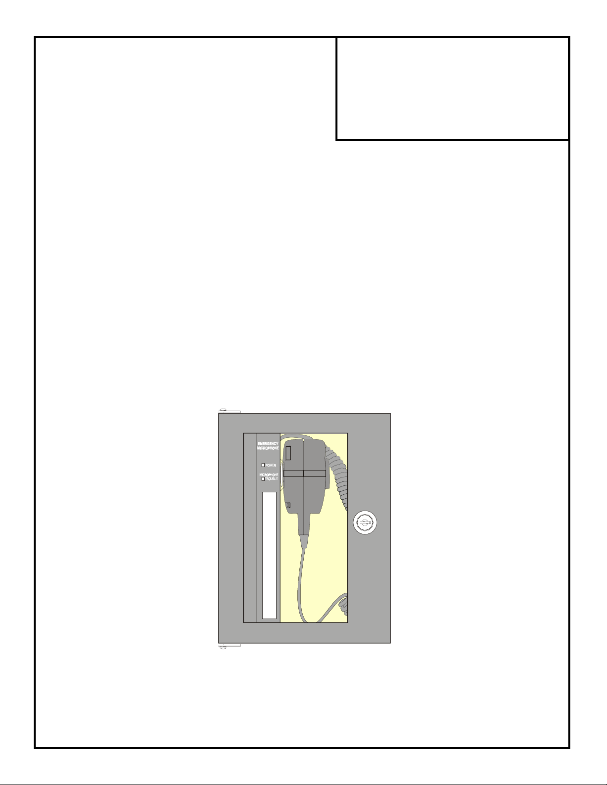
The FC-RMM Remote Microphone Module, which is installed in a CAB-RMRF cabinet as illustrated in Figure 1, provides
paging capabilities for audio systems such as the FC-25/50X and FC-25/50DA.
Following is a list of FC-RMM features:
• Automatic gain control circuit
• All wiring is power-limited
• Supervised microphone
• All external wiring is supervised
• Power On LED
• Trouble LED
• Pluggable terminal blocks
• Remote location for paging
Power Specifications:
• 6 mA non-fire alarm current
• 30 mA when microphone is activated
• 24 VDC Nominal Operating Voltage
Figure 1: FC-RMM in a CAB-RMRF
Document 51247:B 10/01/01 1
Page 2
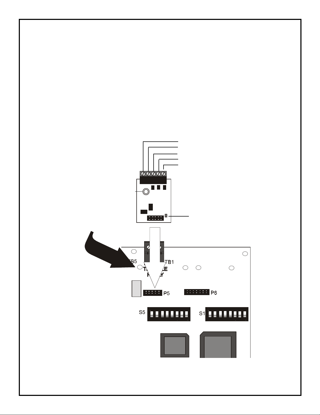
FC-MIM Microphone Interface Module Installation
The supplied FC-MIM Microphone Interface Module must be installed on the main circuit board of the host audio panel.
CAUTION: Circuits contain static-sensitive components. Always ground yourself with a proper wrist strap before
handling any circuits so that static charges are removed from the body. Use static suppressive packaging to protect
electronic assemblies.
To install the FC-MIM:
1. Be sure all power (AC and DC) is removed from the panel before installing the FC-MIM
2. Position the connector on the FC-MIM module over the audio panel main circuit board connector P5 and gently press
down until the module is properly seated. Be careful not to bend or break any pins on the P5 connector
3. Secure the FC-MIM module to the metal standoff on the main circuit board with the supplied screw
+24 VDC Out
24 VDC Return
+ Audio In
- Audio In
Earth
1 2 3 4 5
Standoff Mounting Hole
FC-MIM Microphone Interface Module
Metal Standoff
Remote Microphone Trouble LED
To Connector P5
P5 Connector
Audio Panel Main Circuit Board
2 Document 51247:B 10/01/01
Page 3

Slide-in Label
A slide-in label (part number 51146) is provided with
each FC-RMM assembly. Enter the location of the
microphone speakers on this label along with any
instructions for speaker activation, then slide the label
into the label slot at the bottom of the assembly. (See
Figure 2).
Installation
RMRlbl.cdr
FC-RMM Installation to the CAB-RMRF Cabinet
CAUTION: Circuits contain static-sensitive components. Always
ground yourself with a proper wrist strap before handling any
circuits so that static charges are removed from the body. Use
static suppressive packaging to protect electronic assemblies.
1. Be sure all power (AC and DC) is removed before installing
the FC-RMM.
2. Pull the required wiring into the CAB-RMRF cabinet through
the knockouts provided (refer to Figure 3).
3. Attach wiring to the pluggable terminal blocks and plug onto
the FC-RMM board (refer to Figure 5)
4. Carefully slide the board into the cabinet until it rests in the
slots on the back wall of the box (See Figure 4a).
5. Secure the FC-RMM in the cabinet with the two self-tapping
screws provided (See Figure 4b).
Figure 2: Slide-in Label
Knockouts
rmrknock.cdr
Figure 3: Knockout Locations
CABRM1SA.cdr
CABRMOPN.cdr
Slots
Screw Holes
Figure 4a Figure 4b
Figure 4: Installing the FC-RMM
Document 51247:B 10/01/01 3
Page 4
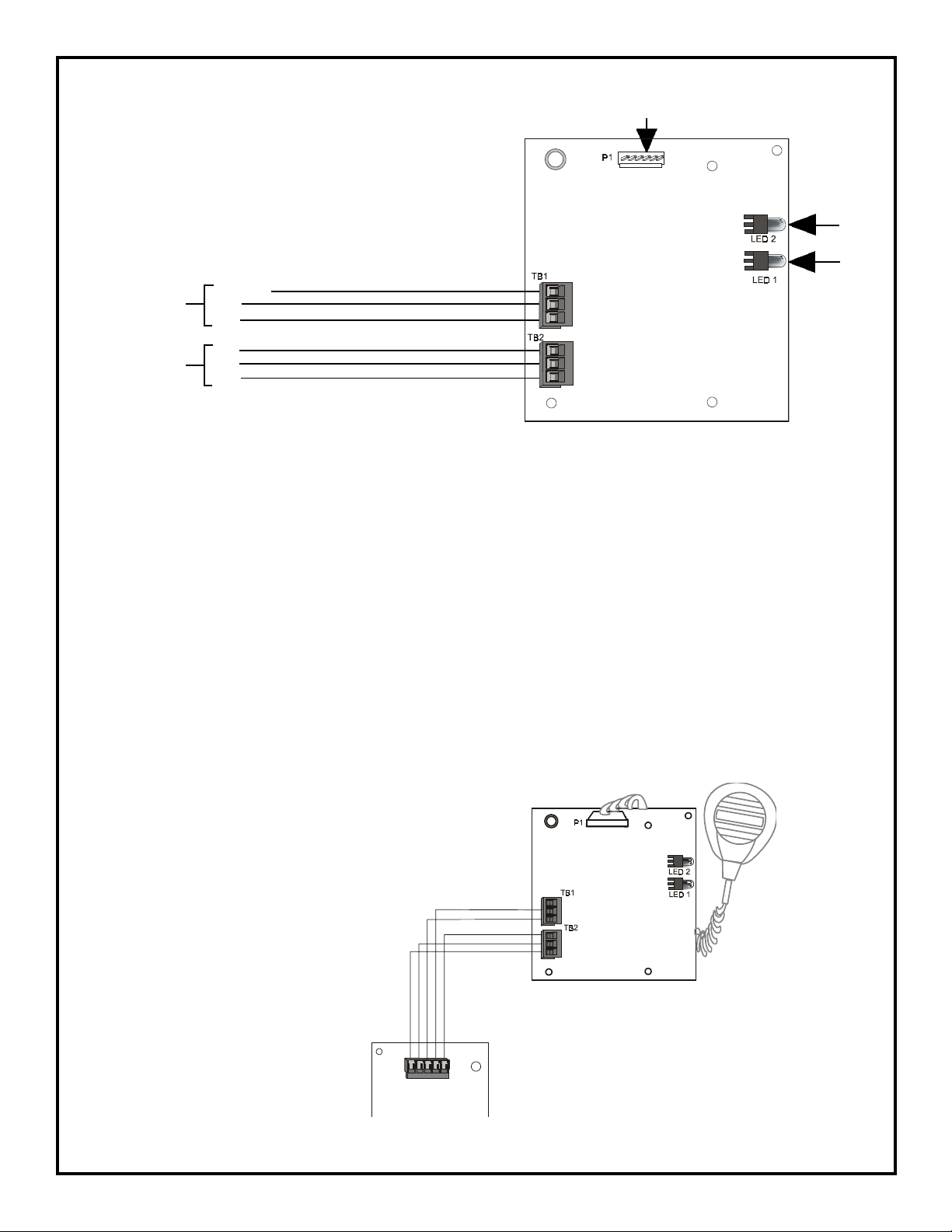
Wiring the FC-RMM and FC-MIM
Microphone Connector
S
To FC-MIM (TB1)
From FC-MIM (TB1)
(4)
(3)
(5)
(2)
(1)
Figure 5: FC-RMM Wiring
TB1: FC-RMM OUTPUT
The FC-RMM audio output terminals [TB1 Terminals 1 (+) and 2 (-)] provide a +6 to +7 VDC voltage audio level when
activated by the microphone PTT (Push-To-Talk) switch. When the PTT is not activated, a +2 VDC voltage is present at
the output of the FC-RMM. The output of the FC-RMM connects to the Microphone Interface Module located in the
FC-25/50X or FC-25/50DA as illustrated in Figure 5.
Shield (3)
- Audio Out (2)
+ Audio Out (1)
Earth (3)
24V return (2)
+24 Vin (1)
Power ON
LED
Trouble
LED
TB2: INPUT POWER SUPPLY
The FC-RMM is powered by the FC-25/50X or FC-25/50DA via the FC-MIM. The FC-MIM distributes +24 VDC to
the FC-RMM. The FC-MIM also supplies Earth and analog grounds to the FC-RMM. Refer to Figure 5.
LED 1 - This yellow LED will light when the FC-RMM microphone is disconnected.
LED 2 - This green LED will light when the FC-RMM is powered.
The FC-RMM can be remotely connected to the FC-25/50X or FC-25/50DA with the FC-MIM. It can be connected up
to 1,500 feet (450 m) with a negligible amount of noise and distortion. The wiring configuration is shown in Figure 6.
Microphone
FC-RMM
TB1
1 2 3 4 5
FC-MIM
(connected to FC-25/50X or FC-25/50DA)
Figure 6: FC-MIM Wiring
4 Document 51247:B 10/01/01
Page 5
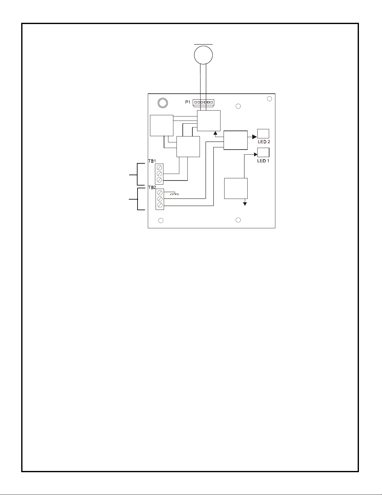
Microphone
PSM - Push-To-Talk Switch Monitor
AGC - Automatic Gain Control
PSC - Power Save Circuit
Audio OUT
Power
PSM
PSC
Output
Driver
AGC
Voltage
Regulator
Mic
Suprvsn
Figure 7: FC-RMM Block Diagram
Power ON
LED
Trouble
LED
Document 51247:B 10/01/01 5
 Loading...