

Page 1

Emergency Command Center
ECC-50/100
ECC-50/100E
Instruction Manual
Document LS10001-000FL-E
9/3/2014 Rev:
P/N LS10001-000FL-E:D ECN 14-790
D
Page 2

Fire Alarm & Emergency Communication System Limitations
While a life safety system may lower insurance rates, it is not a substitute for life and property insurance!
An automatic fire alarm system—typically made up of smoke
detectors, heat detectors, manual pull stations, audible warning
devices, and a fire alarm control panel (FACP) with remote notification capability—can provide early warning of a developing fire.
Such a system, however, does not assure protection against
property damage or loss of life resulting from a fire.
An emergency communication system—typically made up of
an automatic fire alarm system (as described above) and a life
safety communication system that may include an autonomous
control unit (ACU), local operating console (LOC), voice communication, and other various interoperable communication methods—can broadcast a mass notification message. Such a
system, however, does not assure protection against property
damage or loss of life resulting from a fire or life safety event.
The Manufacturer recommends that smoke and/or heat
detectors be located throughout a protected premises following
the recommendations of the current edition of the National Fire
Protection Association Standard 72 (NFPA 72), manufacturer's
recommendations, State and local codes, and the
recommendations contained in the Guide for Proper Use of
System Smoke Detectors, which is made available at no charge
to all installing dealers. This document can be found at http://
www.systemsensor.com/appguides/. A study by the Federal
Emergency Management Agency (an agency of the United
States government) indicated that smoke detectors may not go
off in as many as 35% of all fires. While fire alarm systems are
designed to provide early warning against fire, they do not
guarantee warning or protection against fire. A fire alarm system
may not provide timely or adequate warning, or simply may not
function, for a variety of reasons:
Smoke detectors may not sense fire where smoke cannot
reach the detectors such as in chimneys, in or behind walls, on
roofs, or on the other side of closed doors. Smoke detectors
also may not sense a fire on another level or floor of a building.
A second-floor detector, for example, may not sense a first-floor
or basement fire.
Particles of combustion or “smok e ” from a developing fire
may not reach the sensing chambers of smoke detectors
because:
• Barriers such as closed or partially closed doors, walls, chimneys, even wet or humid areas may inhibit particle or smoke
flow.
• Smoke particles may become “cold,” stratify, and not reach
the ceiling or upper walls where detectors are located.
• Smoke particles may be blown away from detectors by air
outlets, such as air conditioning vents.
• Smoke particles may be drawn into air returns before reaching the detector.
The amount of “smoke” present may be insufficient to alarm
smoke detectors. Smoke detectors are designed to alarm at various levels of smoke density. If such density levels are not created by a developing fire at the location of detectors, the
detectors will not go into alarm.
Smoke detectors, even when working properly, have sensing
limitations. Detectors that have photoelectronic sensing chambers tend to detect smoldering fires better than flaming fires,
which have little visible smoke. Detectors that have ionizing-type
sensing chambers tend to detect fast-flaming fires better than
smoldering fires. Because fires develop in different ways and
are often unpredictable in their growth, neither type of detector is
necessarily best and a given type of detector may not provide
adequate warning of a fire.
Smoke detectors cannot be expected to provide adequate warning of fires caused by arson, children playing with matches
(especially in bedrooms), smoking in bed, and violent explosions
(caused by escaping gas, improper storage of flammable materials, etc.).
Heat detectors do not sense particles of combustion and alarm
only when heat on their sensors increases at a predetermined
rate or reaches a predetermined level. Rate-of-rise heat detectors may be subject to reduced sensitivity over time. For this
reason, the rate-of-rise feature of each detector should be tested
at least once per year by a qualified fire protection specialist.
Heat detectors are designed to protect property, not life.
IMPORTANT! Smoke detectors must be installed in the same
room as the control panel and in rooms used by the system for
the connection of alarm transmission wiring, communications,
signaling, and/or power. If detectors are not so located, a developing fire may damage the alarm system, compromising its ability to report a fire.
Audible warning devices such as bells, horns, strobes,
speakers and displays may not alert people if these devices
are located on the other side of closed or partly open doors or
are located on another floor of a building. Any warning device
may fail to alert people with a disability or those who have
recently consumed drugs, alcohol, or medication. Please note
that:
• An emergency communication system may take priority over
a fire alarm system in the event of a life safety emergency.
• Voice messaging systems must be designed to meet intelligibility requirements as defined by NFPA, local codes, and
Authorities Having Jurisdiction (AHJ).
• Language and instructional requirements must be clearly disseminated on any local displays.
• Strobes can, under certain circumstances, cause seizures in
people with conditions such as epilepsy.
• Studies have shown that certain people, even when they hear
a fire alarm signal, do not respond to or comprehend the
meaning of the signal. Audible devices, such as horns and
bells, can have different tonal patterns and frequencies. It is
the property owner's responsibility to conduct fire drills and
other training exercises to make people aware of fire alarm
signals and instruct them on the proper reaction to alarm signals.
• In rare instances, the sounding of a warning device can cause
temporary or permanent hearing loss.
A life safety system will not operate without any electrical
power. If AC power fails, the system will operate from standby
batteries only for a specified time and only if the batteries have
been properly maintained and replaced regularly.
Equipment used in the system may not be technically compatible with the control panel. It is essential to use only equipment
l
ist
ed for service with your control panel.
Telephone lines needed to transmit alarm signals from a premises to a central monitoring station may be out of service or temporarily disabled. For added protection against telephone line
failure, backup radio transmission systems are recommended.
The most common cause of life safety system malfunction is
inadequate maintenance. To keep the entire life safety system in
excellent working order, ongoing maintenance is required per the
manufacturer's recommendations, and UL and NFPA standards. At a minimum, the requirements of NFPA 72 shall be followed. Environments with large amounts of dust, dirt, or high air
velocity require more frequent maintenance. A maintenance
agreement should be arranged through the local manufacturer's
representative. Maintenance should be scheduled monthly or as
required by National and/or local fire codes and should be performed by authorized professional life safety system installers
only. Adequate written records of all inspections should be kept.
Limit-D-1-2013
2 Emergency Command Center Manual — P/N LS10001-000FL-E:D 9/3/2014
Page 3

Installation Precautions
Adherence to the following will aid in problem-free installation with long-term reliability:
WARNING - Several different sources of power can be
connected to the fire alarm control panel. Disconnect all
sources of power before servicing. Control unit and associated equipment may be damaged by removing and/or inserting cards, modules, or interconnecting cables while the unit is
energized. Do not attempt to install, service, or operate this
unit until manuals are read and understood.
CAUTION - System Re-acceptance Test after Software
Changes: To ensure proper system operation, this product
must be tested in accordance with NFPA 72 after any programming operation or change in site-specific software. Reacceptance testing is required after any change, addition or
deletion of system components, or after any modification,
repair or adjustment to system hardware or wiring. All components, circuits, system operations, or software functions known
to be affected by a change must be 100% tested. In addition,
to ensure that other operations are not inadvertently affected,
at least 10% of initiating devices that are not directly affected
by the change, up to a maximum of 50 devices, must also be
tested and proper system operation verified.
This system meets NFPA requirements for operation at 0-49º
C/32-120º F and at a relative humidity 93% ± 2% RH (noncondensing) at 32°C ± 2°C (90°F ± 3°F). However, the useful
life of the system's standby batteries and the electronic components may be adversely affected by extreme temperature
ranges and humidity. Therefore, it is recommended that this
system and its peripherals be installed in an environment with
a normal room temperature of 15-27º C/60-80º F.
Verify that wire sizes are adequate for all initiating and indicating device loops. Most devices cannot tolerate more than a
10% I.R. drop from the specified device voltage.
Like all solid state electronic devices, this system may
operate erratically or can be damaged when subjected to lightning induced transients. Although no system is completely
immune from lightning transients and interference, proper
grounding will reduce susceptibility. Overhead or outside aerial
wiring is not recommended, due to an increased susceptibility
to nearby lightning strikes. Consult with the Technical Services Department if any problems are anticipated or encountered.
Disconnect AC power and batteries prior to removing or
inserting circuit boards. Failure to do so can damage circuits.
Remove all electronic assemblies prior to any drilling, filing,
reaming, or punching of the enclosure. When possible, make
all cable entries from the sides or rear. Before making modifications, verify that they will not interfere with battery, transformer, or printed circuit board location.
Do not tighten screw terminals more than 9 in-lbs. Overtightening may damage threads, resulting in reduced terminal
contact pressure and difficulty with screw terminal removal.
This system contains static-sensitive components.
Always ground yourself with a proper wrist strap before handling any circuits so that static charges are removed from the
body. Use static suppressive packaging to protect electronic
assemblies removed from the unit.
Follow the instructions in the installation, operating, and programming manuals. These instructions must be followed to
avoid damage to the control panel and associated equipment.
FACP operation and reliability depend upon proper installation.
Precau-D1-9-2005
FCC Warning
WARNING: This equipment generates, uses, and can
radiate radio frequency energy and if not installed and
used in accordance with the instruction manual may
cause interference to radio communications. It has been
tested and found to comply with the limits for class A
computing devices pursuant to Subpart B of Part 15 of
FCC Rules, which is designed to provide reasonable
protection against such interference when devices are
operated in a commercial environment. Operation of this
equipment in a residential area is likely to cause interference, in which case the user will be required to correct
the interference at his or her own expense.
Canadian Requirements
This digital apparatus does not exceed the Class A limits
for radiation noise emissions from digital apparatus set
out in the Radio Interference Regulations of the Canadian Department of Communications.
Le present appareil numerique n'emet pas de bruits radioelectriques depassant les limites applicables aux appareils numeriques de la classe A prescrites dans le
Reglement sur le brouillage radioelectrique edicte par le
ministere des Communications du Canada.
LiteSpeed™ is a trademark; and FireLite® Alarms is a registered trademark of Honeywell International In c. Microsoft® and Windows® are registered
trademarks of the Microsoft Corporation.
©2014 by Honeywell International Inc. All rights reserved. Unauth orized use of this document is strictly prohibited.
Emergency Command Center Manual — P/N LS10001-000FL-E:D 9/3/2014 3
Page 4

Software Downloads
In order to supply the latest features and functionality in fire alarm and life safety technology to our customers, we make
frequent upgrades to the embedded software in our products. To ensure that you are installing and programming the latest
features, we strongly recommend that you download the most current version of software for each product prior to
commissioning any system. Contact Technical Support with any questions about software and the appropriate version for a
specific application.
Documentation Feedback
Your feedback helps us keep our documentation up-to-date and accurate. If you have any comments or suggestions about our
online Help or printed manuals, you can email us.
Please include the following information:
•Product name and version number (if applicable)
•Printed manual or online Help
•Topic Title (for online Help)
•Page number (for printed manual)
•Brief description of content you think should be improved or corrected
•Your suggestion for how to correct/im prove documentation
Send email messages to:
FireSystems.TechPubs@honeywell.com
Please note this email address is for documentation feedback only. If you have any technical issues, please contact Technical
Services.
4 Emergency Command Center Manual — P/N LS10001-000FL-E:D 9/3/2014
Page 5

Table of Contents
Section 1: Product Description .............................................................................................12
1.1: Product Features ..........................................................................................................................................12
1.2: Input/Output Circuit Specifications.............................................................................................................14
1.2.1: ECC-50/100 Main Control Board .....................................................................................................14
1.2.2: Display Board....................................................................................................................................18
1.2.3: ECC-CE6 Circuit Expander Module.................................................................................................19
1.3: Controls and Indicators................................................................................................................................20
1.3.1: Push-Button Controls ........................................................................................................................20
1.3.2: LED Indicators (visible with door closed) ........................................................................................21
1.3.3: LED Indicators (visible with door and dress panel open) .................................................................21
1.4: Components.................................................................................................................................................21
1.5: Optional Equipment.....................................................................................................................................23
1.6: UL 464 Low Frequency Sounders...............................................................................................................24
Section 2: Installation.............................................................................................................26
2.1: Mounting Options........................................................................................................................................26
2.2: Backbox Installation....................................................................................................................................26
Removing the Dress Panel....................................................................................................................26
Removing the Chassis Assembly .........................................................................................................27
Mounting the Backbox.........................................................................................................................28
2.3: Operating Power..........................................................................................................................................31
2.3.1: AC Power and Earth Ground Connection.........................................................................................31
2.3.2: Secondary Power Source (Batteries).................................................................................................32
2.4: Auxiliary DC Power Output Connections ...................................................................................................33
2.5: Input/Initiating Circuits ...............................................................................................................................33
2.5.1: CMD Inputs.......................................................................................................................................33
2.5.2: External Audio Input.........................................................................................................................34
2.5.3: NAC Follower Input................................. .................................. ................................. ......................35
2.5.4: Night Ring .........................................................................................................................................35
2.6: Output Circuits.............................................................................................................................................36
2.6.1: Relays ................................................................................................................................................36
MNS Active Relay - TB1............................................... ......................................................................36
Trouble Relay - TB2.................................................. .................................. .........................................36
AC Power Loss Relay - TB3................................................................................................................36
2.6.2: Speaker Circuits.................................................................................................................................37
2.6.3: Notification Appliance Circuit ..........................................................................................................38
2.6.4: Speaker Volume Control...................................................................................................................39
2.6.5: FACP Data Bus ............................................................................................. ....................................40
ACS Mode Wiring..................................................... .................................. .........................................41
2.7: ECC-LOC Local Operator Console.............................................................................................................42
2.8: ECC-RPU Remote Page Unit......................................................................................................................44
2.9: ECC-RM Remote Microphone....................................................................................................................46
2.10: ECC-50DA, ECC-125DA, ECC-50BDA Distributed Audio Amplifiers..................................................47
2.11: Shielding for External Device Wiring .......................................................................................................47
2.12: UL Power-limited Wiring Requirements........................................................................... ........................49
2.13: Installation of Option Modules..................................................................................................................50
2.13.1: ECC-CE6 Circuit Expander Module...............................................................................................50
2.13.2: Audio Amplifier Module (ECC-50W-25/70V) ...............................................................................50
Installation............................................................................................................................................50
Power and Control Cables....................................................................................................................52
Configuration........................................................................................................................................52
......
ECC-50/100 Configurations with ECC-50W-25/70V.......
2.13.3: 70.7 V
2.14: Addressing External Data Bus Devices.....................................................................................................55
Transformer (ECC-XRM-70V) ....................................................................................55
RMS
.............................................................53
Emergency Command Center Manual — P/N LS10001-000FL-E:D 9/3/2014 5
Page 6

Table of Contents
Section 3: Programming........................................................................................................59
3.1: Main Menu - User Programming.................................................................................................................60
3.1.1: Password Options ..............................................................................................................................60
3.1.2: General/NAC Options .......................................................................................................................61
General Options....................................................................................................................................61
NAC Options........................................................................................................................................62
Console Control....................................................................................................................................63
3.1.3: Address Assignment..........................................................................................................................63
Remote Microphone / Operator Console Address Assignments..........................................................63
Speaker Circuit Address Assignment...................................................................................................64
3.1.4: Message Buttons................................................................................................................................65
Message Buttons............................................................ .................................. .....................................65
CMD Input Style ..................................................................................................................................66
3.1.5: Date / Time ........................................................................................................................................66
3.1.6: Send to Panel .....................................................................................................................................66
3.2: Main Menu - Utilities...................................................................................................................................67
3.2.1: Message Recording............................................................................................................................67
3.2.2: USB File Options...............................................................................................................................68
3.3: Main Menu - Informational .........................................................................................................................68
3.3.1: Informational .....................................................................................................................................69
Speaker Circuit Buttons........................................................................................................................69
Version Information..............................................................................................................................69
History Information................................ .................................. .................................. ..........................70
3.4: Recording Custom Messages.......................................................................................................................70
3.4.1: Message Record Mode ............................................................. .................................. .......................70
3.4.2: External Audio Input .........................................................................................................................71
Recording with External Audio - Example ..........................................................................................72
3.4.3: Microphone........................................................................................................................................73
Recording with Microphone - Example ................................ .................................. .............................73
3.4.4: Erasing a User Message.....................................................................................................................74
3.4.5: Voice Loader Software......................................................................................................................74
Writing a Message to the Panel............................................................................................................75
Reading a Message from the Panel.................................................... .................................. .................75
Moving a Message to a Different Slot..................................................................................................75
3.5: Programmed Activation by FACP ...............................................................................................................75
3.5.1: MS-9600(UD)LS and MS-9200UDLS..............................................................................................76
FACP Programming .............................................................................................................................77
FACP Message Assignment - Speaker Specific...................................................................................77
FACP Message Assignment - Zone Specific........................................................................................78
FACP Programming Menus .................................................................................................................79
Section 4: Operating Instructions.........................................................................................82
4.1: Main Control Panel Keypad Labels.............................................................................................................82
4.2: ECC-50/100 Switch Functions ....................................................................................................................82
4.3: LED Indicators.............................................................................................................................................83
4.4: Operation......................................................................................................................................................85
4.4.1: Paging from the Microphone.............................................................................................................85
4.4.2: Manual Message Control...................................................................................................................85
4.4.3: Fire Alarm Response, System Configured for Fire Only ..................................................................86
4.4.4: Fire Alarm Restoral, System Configured for Fire Only ....................................................................86
4.4.5: Manual Activation.............................................................................................................................86
4.4.6: Manual Activation Restoral............................................................................... ................................87
4.4.7: Alarm/Alert Response, System Configured for Mass Notification Only..........................................87
4.4.8: Alarm/Alert Restoral, System Configured for Mass Notification Only............................................87
4.4.9: Alarm/Alert Response, System Configured for Combo Fire/Mass Notification with Fire Priority..88
4.4.10: Alarm/Alert Restoral, System Configured for Combo Fire/Mass Notification with Fire Priority..88
4.4.11: Alarm/Alert Response, System Configured for Combo Fire/Mass Notification with Mass Notifica-
6 Emergency Command Center Manual — P/N LS10001-000FL-E:D 9/3/2014
Page 7

Table of Contents
tion Priority..................................................................................................................................................88
4.4.12: Alarm/Alert Restoral, System Configured for Combo Fire/Mass Notification with Mass Notification
Priority.........................................................................................................................................................89
4.4.13: Trouble Condition Response............................. ..............................................................................89
4.4.14: Trouble Condition Restoral............................................................................................. ................90
4.4.15: External Audio Input Operation................................... .................................. .................................91
Section 5: Getting Started ......................................................................................................92
5.1: System Requiring up to 50 Watts of Audio Power......................................................................................92
5.2: System Requiring Up to 100 Watts of Audio Power...................................................................................92
5.3: System Requiring Greater Than 100 Watts of Audio Power.......................................................................92
Section 6: Power Supply Calculations..................................................................................93
6.1: Overview......................................................................................................................................................93
6.2: Calculating the AC Branch Circuit..............................................................................................................93
6.3: Calculating the System Current Draw.........................................................................................................93
6.3.1: Overview ...........................................................................................................................................93
6.3.2: How to use Table 6.2 to calculate system current draws...................................................................94
6.4: Calculating the Battery Size ........................................................................................................................95
6.4.1: NFPA Battery Requirements.............................................................................................................95
6.4.2: Selecting and Locating Batteries.......................................................................................................95
Appendix A: Digital Voice Messages....................................................................................96
Appendix B: Wiring Requirements........................................................................................98
Appendix C: Canadian Applications.....................................................................................99
C.1: Audio Room Isolator Modules....................................................................................................................99
C.1.1: Description........................................................................................................................................99
C.1.2: Panel Programming...........................................................................................................................99
C.1.3: Applications....................................................................................................................................100
Index.......................................................................................................................................105
ECC-50/100 and ECC-LOC OPERATING INSTRUCTIONS.................................................109
Emergency Command Center Manual — P/N LS10001-000FL-E:D 9/3/2014 7
Page 8

This control panel has been designed to comply with standards set forth by the following regulatory agencies:
• Underwriters Laboratories/Underwriters Laboratories Canada
• National Fire Protection Association
Before proceeding, the installer should be familiar with the following documents.
NFPA Standards
This Fire Alarm Control Panel complies with the following NFPA Standards:
NFPA 72 National Fire Alarm Code
Note: Audible signal appliances used in public mode applications, are required to have
minimum sound levels of 75 dBA at 10 feet (3 meters) and a maximum level of 120 dBA at the
minimum hearing distance from the audible appliance.
T o ensure that the appliance is clearly heard, the audible appliance sound level must be at least
15 dBA above the average ambient sound level or 5 dBA above the maximum sound level wit h
a duration of at least 60 seconds, depending on which level is greater, with the sound level
being measured 5 feet (1.5 meters) above the floor.
Underwriters Laboratories Documents:
UL 38 Manually Actuated Signaling Boxes
UL 464 Audible Signaling Appliances
UL 864 Standard for Control Units for Fire Protective Signaling Systems
UL 1480 Speakers for Fire Protective Signaling Systems
UL 1638 Visual Signaling Appliances
UL 1711 Amplifiers for Fire Protective Signaling Systems
UL 1971 Signaling Devices for Hearing Impaired
UL 2572 Communication and Control Units for Mass Notification Systems
CAN/ULC - S524-01 Standard for Installation of Fire Alarm Systems
CAN/ULC - S527-11 Standard for Control Units for Fire Alarm Systems
This Class (A) digital apparatus complies with Canadian ICES-003.
Cet appareil numérique de la classe (A) est conforme à la norme NMB-003 du Canada.
Other:
Canadian Electrical Code, Part 1
NEC Article 250 Grounding
NEC Article 300 Wiring Methods
NEC Article 760 Fire Protective Signaling Systems
Applicable Local and State Building Codes
Requirements of the Local Authority Having Jurisdiction (LAHJ)
Fire•Lite Documents:
Fire•Lite Device Compatibility Document Document #15384
ECC Distributed Audio Manual Document #LS10027-000FL-E
ECC-FFT Manual Document #LS10031-000FL-E
ECC-LOC Installation Document Document #LS10028-000FL-E
ECC-RPU Installation Document Document #LS10030-000FL-E
ECC-RM Installation Document Document #LS10029-000FL-E
ECC-CE6 Installation Document Document #LS10033-000FL-E
ECC-CE4 Installation Document Document #LS10002-000FL-E
ECC-50W-25/70V Installation Document Document #LS10035-000FL-E
ECC-XRM-70V Installation Document Document #LS10032-000FL-E
MS-9200UDLS Series Manual Document #52750
MS-9600(UD)LS Technical Manual Document #52646
8 Emergency Command Center Manual — P/N LS10001-000FL-E:D 9/3/2014
Page 9
FIRE SYSTEM
ACTIVE
SYSTEM
CONTROL
ALL
CALL
1
2
3
4
5
6
7
8
9
10
11
12
13
18
19
20
21
22
23
24
16
17
14
15
LIT
FI
®
AL
by Honeywell
FIRE SYSTEM
ACTIVE
SYSTEM
CONTROL
ALL
CALL
1
2
3
4
5
6
7
8
9
10
11
12
13
18
19
20
21
22
23
24
16
17
14
15
LIT
FI
®
AL
by Honeywell
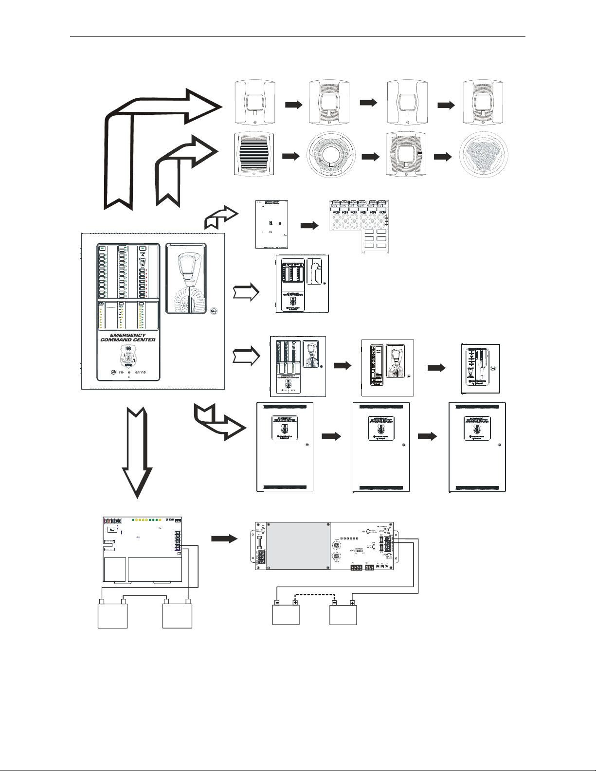
Speaker Circuits
TB20 & TB21
internal options
ECC-50W-25/70V
optional amplifier
ECC-CE6
circuit expander
ECC-50DA
50W remote amplifier
ECC-RPU
remote page unit
ECC-RM
remote microphone
remote
consoles
distributed
audio
ECC-125DA
125W remote amplifier
ECC-LOC
local operator console
CHG-120F
charger
CHG-75
charger
external battery
charger - J7
TB4
TB12
TB22
Figure 1.1 Peripheral Devices
eccperi.wmf
NAC Circuit
TB19
visual only
ECC-FFT
firefighter telephone
ECC-50BDA
50W remote amplifier
Emergency Command Center Manual — P/N LS10001-000FL-E:D 9/3/2014 9
Page 10
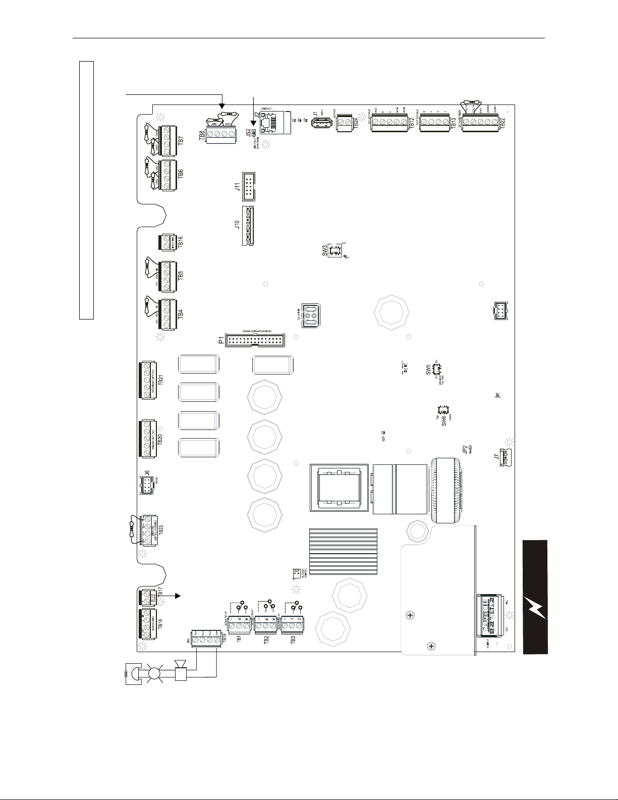
+
+
+
J12
TB15
J9
RTZM
DISPLAY
C
A
U
T
I
O
N
!
H
I
G
H
V
O
L
T
A
G
E
ecc50layo.wmf
AC Power
(Supervised,
Nonpower-Limited)
120 VAC, 60 Hz, 3.5 ampsor230 VAC, 50 Hz, 2.0 amps
Special Application DC Power Output (24 VDC)
Supervised, Power-Limited (Class 2) circuit
Supervise with a power supervision relay EOLR-1
Nonresettable Power suitable for powering control
modules and power supervision relays.
NAC Follower Input
Supervised, Power-
Limited (Class 2)
circuits
24 VDC filtered (10
mA maximum),
Requires an FACP
End-of-Line Resistor
AC Loss, MNS Active, &
Fixed Trouble Relay
Non-supervised relay contacts
Contact rating:
2.0 amps @ 30 VDC (resistive)
0.5 amps @ 30 VAC (resistive)
Contacts shown below in
normal condition (AC power
with no alarm, trouble, or
supervisory activity)
AC Fail Safe Trouble relay
switches to the NO position
during trouble conditions and
under loss of all power.
Flash Memory Load Enable
Switch: UP is normal
position for switch, DOWN
position allows for factory
software upgrades
Ethernet Port J2/
for local programming
using a personal
computer and web-
based utility
Battery
24 VDC, supervised,
Non-power-limited,
26 AH maximum
Notification
Appliance Circuit
Style Y (Class B) or
Style Z (Class A)
Supervised, Power-
Limited (Class 2)
(Special
application) 2.0
amps max.
Regulated power:
200mA max.
ELR, 4.7K, 1/2W
(for Style Y wiring)
Optional 50W Amplifier
connectors
Optional 70V
Transformer connector
Optional CE6 Circuit
Expander Connector
Display Board
connector
Speaker Volume Control Override
Style Y (Class B) or Style Z (Class A)
Supervised, Power-Limited (Class 2)
(Special application) 0.25 amps max.
4.7K ELR, 1/2W required for Style Y
(Class B) wiring
Primary/Secondary Speaker Circuits
Style Y (Class B) or Style Z (Class A)
Supervised, Power-Limited (Class 2)
50W integrated output power. Use of
secondary circuit requires optional
ECC-50W-25/70V amplifier
15K ELR, 1W required for Style Y
(Class B) wiring
CMD1 & CMD2 Command Input Circuits
Trigger by contact closure or NAC reverse
polarity (ELR required)
alarm polarity shown.
CMD3 - CMD8 Command Input Circuits
Trigger by contact closur e (ELR required)
alarm polarity shown.
(inputs only)
Night Ring Input
Trigger by contact closure
External Operator Interface Power
Supervised, Power-Limited
(Class 2) circuit
24 VDC Nonresettable Power for
external operator interface components.
External Data Bus
Supervised, Power-Limited
(Class 2) data connections to
external operator interface
components
FACP Data Bus
Supervised, Power-Limited
circuit dedicated as FACP
serial bus connection
External Audio Riser
Style Y (Class B) or Style Z (Class A)
Supervised, Power-Limited (Class 2)
audio connection to external operator
interface components
Speaker
Voltage
Switch
To disable
ground fault
detection,
remove
jumper/shunt
from JS2.
Basic System Connections - Main Control Board (Section 1.2.1)
Cut jumper to use
external charger
Backup
amplifier
test switch
USB-A Port J1/
for local program
download
10 Emergency Command Center Manual — P/N LS10001-000FL-E:D 9/3/2014
Page 11
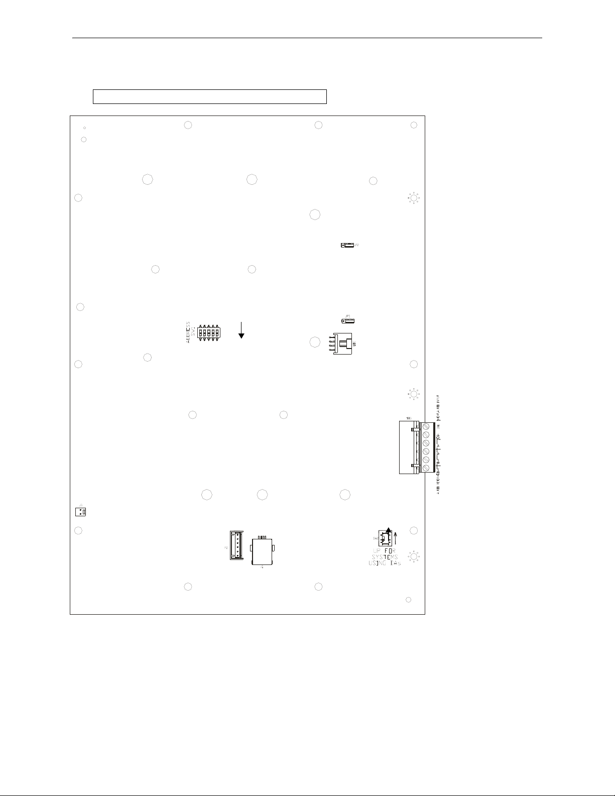
TB5- External Audio Input/
Audio Riser
SW1- Dipswitch for
BUS addressing
ON
JP5 isolation/ground
when powered by
source other than
main control board
J2- Connection to
main control board
P2- Microphone
connector
J1- USB connector -
connection to a PC for
downloading messages
Refer to Section 3.4.5
on page 74.
Basic System Connections - Display Board (Section 1.2.2)
disp.wmf
SW2- Distributed Audio Switch
set to UP position if any
ECC-50/125DAs are installed
in the system.
Default is the DOWN position.
JP2 - External Data
Bus termination
Emergency Command Center Manual — P/N LS10001-000FL-E:D 9/3/2014 11
Page 12

Section 1: Product Description
The Fire•Lite Emergency Command Center ECC-50/100 is a single channel, 50 watt, 25 V
emergency voice evacuation panel that may be used for fire applications, mass notification applications, or both. The ECC-50/100 comes standard with one speaker circuit. The panel provides the
ability to record fourteen field programmable messages (up to 60 seconds each) with an integral
microphone or from an external audio source. An integral power supply with battery charger supplies operational power. A 50 watt audio amplifier is built into each panel. An optional second 50
watt amplifier (ECC-50W-25/70V) is also available for backup purposes or to provide an additional
50 watts. The backup amplifier is available in either 25 volts or 70 volts depending on which application is necessary.
Automatic activation of the ECC-50/100 by an FACP is possible via eight Command Input Circuits
(CMD) or via the ACS/ANN Bus serial communications link from the MS-9600(UD)LS and
MS-9200UDLS FACPs.
T wo Command Input Circuits can be independently field programmed for activation by an FACP
Notification Appliance Circuit reverse polarity or by closure of a supervised normally open contact
and six Command Input Circuits activate on contact closure. CMD 1 and CMD 2 provide terminals
for NAC input and output to allow installation of the audio panel anywhere along the NAC circuit
being used to activate it.
If the message generator fails, the system automatically reverts to a backup tone generator.
Power is fed independently
down the other. Full output power of 50 watts per amplifier is generated while in a low battery condition. Power is not diminished when the optional 70 V
is amplified utilizing modern integrated circuits as opposed to transformer technology. This provides for very low signal distortion for crystal clear audio.
to each amplifier so that a short circuit in one amplifier will not shut
transformer module is installed. Aud io
RMS
RMS
,
Primary applications for the audio panels include protecting structures such as military facilities,
restaurants, schools, auditoriums, places of worship, buildings with occupancies over 50, etc. The
ECC-50/100 is designed to interface directly to addressable or conventional (CMD inputs 1-8) fire
alarm control panels or can be used with the ECC-50/125DA panel to distribute audio in systems
that require more than 100 watts.
For Canadian applications, refer to Appendix C on page 99.
1.1 Product Features
• Modular design for maximum system flexibility and easy expansion
• Removable terminal blocks for ease of servicing and module replacement
• 50 watts of 25 V
• 2 amp Notification Appliance Circuit (NAC) output, sync generator, or follower for protocols:
– System Sensor
– Wheelock
–Gentex
• Optional 70.7 V
speaker wiring continues to be supervised in standby, alarm and when background music is
playing with this optional transformer installed)
• Eight Command Input Circuits to activate messages 1 to 8:
– CMD1 and CMD2 are field selectable to be activated from 12 or 24 VDC Notification
Appliance Circuits (reverse polarity) or contact closures
– CMD3-CMD8 are activated by contact closures
• Speaker Circuits
– single Style Y (Class B) or Style Z (Class A) speaker circuit
RMS
audio power (expandable to 100 watts)
RMS
conversion transformer available for the primary amplifier (note that
12 Emergency Command Center Manual — P/N LS10001-000FL-E:D 9/3/2014
Page 13

Product Features Product Description
– two Style Y (Class B) or Style Z (Class A) speaker circuits (with optional ECC-50W-
25/70V Audio Amplifier installed)
– eight Style Y (Class B) or Style Z (Class A) speaker circuits (with optional ECC-50W-
25/70V and ECC-CE6 installed)
• ECC-50/100 can be controlled by an FACP via the ANN/ACS (EIA-485) link. Compatible
FACPs include the MS-9600(UD)LS and MS-9200UDLS.
• Integral supervised microphone
• Microphone time-out feature which reverts back to prerecorded message if emergency page
exceeds the programmed time
• Up to 14 recorded messages
• 14 prerecorded messages for fire, emergency, and weather alerts
• Field-selectable message and custom message recording capability using the local
microphone, a USB port, or an external audio input
• External Audio Input can be used for background music
• Up to 60 second message duration for all messages
• Integral tone generators field selectable for multiple tone types
• Powered by integral AC power supply or bat teries during AC fail
• Programmable delay of immediate, 2 hours or 6 hours reporting of AC Loss
• Piezo sounder for local trouble
• 100 event history log
• Three Form-C relays:
– AC Power Loss Relay - TB1
– System Trouble Relay - TB2
– MNS Active - TB3
• 500 mA (0.5A) Special Application (auxiliary power) output for addressable modules when
interfaced with compatible addressable FACPs and End-of-Line power supervision relays
• System Status LEDs (refer to “Controls and Indicators” on page 20)
• Integral Dress Panel
• Optional TR-CE semi-flush trim ring
• Any combination of up to eight (8) of:
– Optional ECC-RM Remote Microphone (includes cabinet).
– Optional ECC-RPU Remote Page Unit (includes cabinet)
– Optional ECC-LOC (includes cabinet)
• Optional ECC-CE6 Circuit Expander
• Optional ECC-50W-25V amplifier, 50 watts, 25 volts
• Optional ECC-50W-70V amplifier, 50 watts, 70 volts
• Optional ECC-50DA distributed amplifier, 50 watts
• Optional ECC-125DA distributed amplifier, 125 watts
• Optional ECC-50BDA distributed amplifier, 50/100 watts
Emergency Command Center Manual — P/N LS10001-000FL-E:D 9/3/2014 13
Page 14

Product Description Input/Output Circuit Specifications
1.2 Input/Output Circuit Specifications
1.2.1 ECC-50/100 Main Control Board
AC Power - TB15
ECC-50/100: 120 VAC, 60 Hz, 3.5 amps (HOT, NEU)
ECC-50/100E: 240 VAC, 50 Hz, 2.0 amps (HOT=HotLeg1, NEU=H otLeg2)
Wire size: minimum #14 AWG (2.00mm
Battery (lead acid only) - J7
Maximum Charging Circuit: Normal Flat Charge - 27.3V @ 2.8 amps
Maximum Charger Capacity: 26 Amp Hour battery. (ECC cabinet holds max. 18 Amp Hour Battery.
Minimum Battery Size: 12 Amp Hour
MNS Active Relay - TB1
Form-C relay contact rating: 2.0 amps @ 30 VDC (resistive), 0.5 amps @ 30 VAC (resistive),
Form-C Trouble Relay - TB2
Form-C relay contact rating: 2.0 amps @ 30 VDC (resistive), 0.5 amp @ 30 VAC (resistive).
AC Loss Relay - TB3
2
) with 600 V insulation.
Form-C relay contact rating: 2.0 amps @ 30 VDC (resistive), 0.5 amps @ 30 VAC (resistive),
NAC Output - TB19, Terminals 1 (B+), 2 (A+), 3 (A-), & 4 (B-)
One (1) Style Y (Class B) or Style Z (Class A) circuit
Power-limited circuitry (Class 2), supervised
Nominal operating voltage: 24 VDC
Maximum signaling current for special application power: 2.0 amps
Maximum signaling current for regulated power: 200mA
Current limit: fuseless, electronic, power-limited
Maximum wiring impedance: 1
End-Of-Line Resistor: 4.7 K, ½ watt, (P/N 71252) required for Style Y (Class B) operation
Refer to the Device Compatibility Document for listed compatible devices.
NAC Follower - TB18, Terminals 3 (IN+), 4 (IN-), 1 (OUT+) & 2 (OUT-)
Connections for FACP NAC synchronization trigger signal
Output terminals: pass-through to other system components
Trigger input voltage: 9 to 32 VDC, 24 VDC rated
Input current draw in Alarm condition: 10 mA at rated voltage
Special Application Power (Aux. Power) - TB17 Terminals 1(+) & 2(-)
Up to 500 mA @ 24 VDC of special application power is available for powering addressable modules and associated End-of-Line power supervision relays.
Power-limited (Class 2) circuitry. Refer to the Device Compatibility Document for a list of compatible devices.
Speaker Volume Control Override - TB23, Terminals 1 (B+), 2 (A+), 3 (A-), & 4 (B-)
Style Y (Class B) or Style Z (Class A) circuit
Special Application power
Power-limited (Class 2) circuitry, supervised
Nominal operating voltage: 24 VDC
Maximum signaling current: 0.25 amps
Current limit: fuseless, electronic, power-limited
End-Of-Line Resistor: 4.7 K, ½ watt, (P/N 71252) required for Style Y (Class B) operation
14 Emergency Command Center Manual — P/N LS10001-000FL-E:D 9/3/2014
Page 15

Input/Output Circuit Specifications Product Description
Speaker Circuits
Primary Speaker Circuit - TB20, Terminals 1(+) & 2(-) Style Y (Class B), 4(+) & 5(-) Style Z
(Class A), 3 Shield (Standby and Alarm Polarity Shown) on main control board
Secondary Speaker Circuit (with optional amplifier only) - TB21, Terminals 1(+) & 2(-)
Style Y (Class B), 4(+) & 5(-) Style Z (Class A), 3 Shield (Standby and Alarm Polarity Shown) on
main control board
Power-limited (Class 2) circuitry
Operation: Circuit can be wired Style Y (Class B) or Style Z (Class A)
Normal Operating Voltage: 25 V
(70.7 V
@ 700 mA max. with maximum Load Impedance of 100operation possible by plug-
RMS
@ 2 amps max. and maximum Load Impedance of 12.5
RMS
ging optional ECC-XRM-70V conversion transformer into J12 of th e m a in control board).
Output Power: 50 watts, standard; 100 watts with optional amplifier (100 watts total, maximum,
allowed in standby for background music)
Frequency Range: 800 - 2,800 Hz
Maximum total capacitance for each speaker circuit: 250 µF.
End-of-Line Resistor required for Style Y circuit: 15 K, 1 watt (P/N : ELR-15K)
Command Input Circuits (alarm polarities shown)
• CMD1 - TB4 Terminals 3(+) & 4(-) are input terminals and Terminals 1(-) and 2(+) are output
terminals which provide feed through of the NAC circuits to NAC devices downstream;
provides internal trouble relay rated at 3.0 amps maximum
• CMD2 - TB5 Terminals 3(+) & 4(-) are input terminals and Terminals 1(-) and 2(+) are output
terminals which provide feed through of the NAC circuits to NAC devices downstream
• CMD3 - TB6 Terminals 1(+) & 2(-) are input terminals for contact closure only
• CMD4 - TB6 Terminals 3(+) & 4(-) are input terminals for contact closure only
• CMD5 - TB7 Terminals 1(+) & 2(-) are input terminals for contact closure only
• CMD6 - TB7 Terminals 3(+) & 4(-) are input terminals for contact closure only
• CMD7 - TB8 Terminals 1(+) & 2(-) are input terminals for contact closure only
• CMD8 - TB8 Terminals 3(+) & 4(-) are input terminals for contact closure only
Power-limited (Class 2) and supervised circuitry
Normal Operating Voltage Range: 10.5 VDC - 29 VDC; Maximum Voltage: 29 VDC
NAC Reverse Polarity Current (requires End-of-Line Resistor from NAC): 1.6 mA maximum.
Contact Closure Operation Current (requires 4.7K, ½ watt End-of-Line Resistor P/N 27072): 6.6
mA maximum
Maximum Wiring Impedance CMD1 - CMD8 (Contact Closure Operation): 200
Maximum Input Impedance:
• CMD1 & CMD2 (Reverse Polarity Operation): 20K
• CMD1 - CMD8 (Contact Closure Operation): 4.75K
Night Ring Input - TB16, Terminals 1 (+) & 2 (-)
Contact closure input
Isolated, nonsupervised
Operation current: 3.8 mA, maximum
Maximum wiring impedance: 30K
Minimum isolation withstand voltage: 1500 V
RMS
External Operator Interface Power Output - TB24, Terminals 1 (PWR, +) & 2 (GND, -)
Non-resettable power for external operator interface components
Power-limited (Class 2) circuitry, Supervised
Nominal operating voltage: 24 VDC
Maximum output current: 0.80 amps
Current limit: fuseless, electronic, power-limited circuitry
Emergency Command Center Manual — P/N LS10001-000FL-E:D 9/3/2014 15
Page 16

Product Description Input/Output Circuit Specifications
External Data Bus (EIA-485) - TB12, Terminals 2 (B), 3 (A) , 4 (BRTN), 5 (ARTN), &
1(SHLD)
Data connections for external operator interface components
Redundant transceiver circuitry for Class A operability
Power-limited (Class 2) circuitry, supervised
Maximum wiring impedance: 13.2
FACP Data Bus (EIA-485) - TB13, Terminals 1 (B IN), 2 (A IN), 3 (B OUT), & 4 (A OUT)
Dedicated connection to FACP serial bus
Output terminals: pass-through to other system components
Isolated, supervised
Minimum isolation withstand voltage: 1500 V
RMS
Maximum wiring impedance: 40 (ANN-BUS)/26 (ACS BUS)
External Audio Riser TB22, Termina ls 1 (OUT+), 2 (OUT-), 4 (IN+), 5 (IN-), & 3 (SHLD)
Style Y (Class B) or Style Z (Class A) audio connections to external operator interface components
Power-limited (Class 2) circuitry, supervised
Audio signal level: 3.85 V
, maximum
RMS
Frequency range: 800 - 2,800 Hz
Frequency range (ECC-50/125DA): 800 Hz - 2.8 KHz
NOTE: Zero impedance to ground will cause a ground fault.
16 Emergency Command Center Manual — P/N LS10001-000FL-E:D 9/3/2014
Page 17
Input/Output Circuit Specifications Product Description
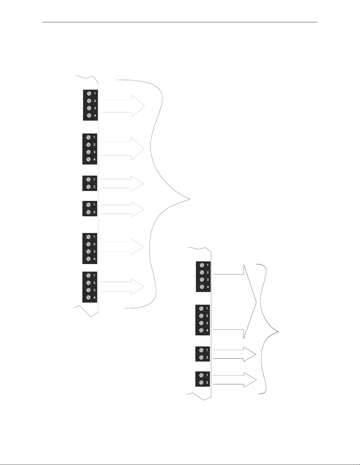
TB20
TB21
TB19
TB24
TB23
TB17
Primary 50W
Speaker Circuit
50W max = 3.3
amps from supply
Secondary 50W
Speaker Circuit-
Optional Amplifier
Installed
NAC Circuit
2.0 amps max.
Aux. Power
0.5 amp max.
Speaker Volume
Control Override
0.25 amp max.
External Operator
Interface Power
0.8 amp max.
Alarm
7.5 amps
max.
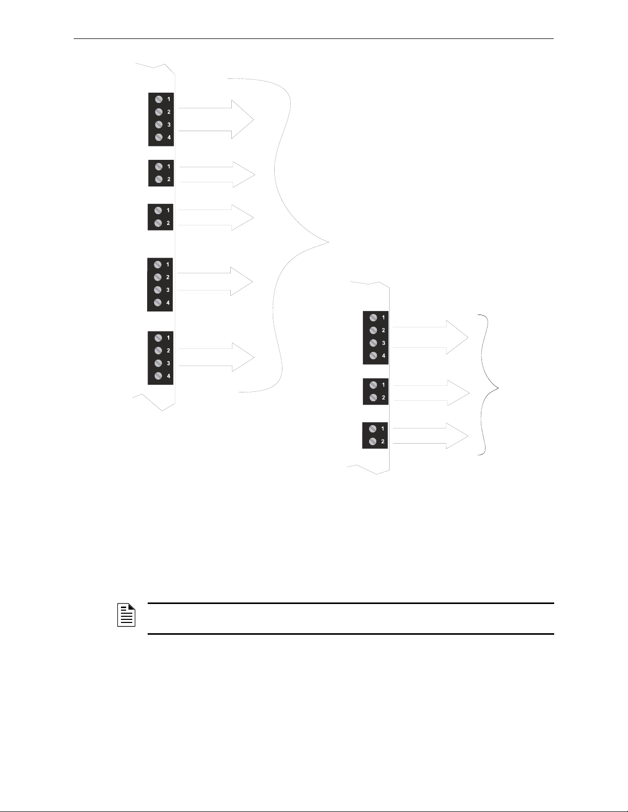
Figure 1.2 Current Availability - 100 Watt System
TB20
TB21
TB24
TB17
50W max = 3.3
amps from supply
Primary 50W
Speaker Circuit
Secondary 50W
Speaker Circuit-
Optional Amplifier
Installed
Aux. Power
External Operator
Interface Power
combined 10W
max = 0.66 amps
from supply
0.5 amp max.
0.8 amp max.
Standby
2.0 amps max.
(includes
background music).
Current Availability
The following figures illustrate the maximum current allowed for each output circuit in the panel
and the total output current available from the power supply. Refer to Section 6, “Po wer Supply
Calculations” for additional current draw by option cards that must be considered when determining total standby and alarm currents.
Emergency Command Center Manual — P/N LS10001-000FL-E:D 9/3/2014 17
Page 18
Product Description Input/Output Circuit Specifications
TB20
TB19
TB17
TB23
TB24
TB20
TB17
TB24
Primary 50W
Speaker Circuit
10W max. = 0.66
amps from supply
NAC Circuit
2.0 amps max.
Aux. Power
0.5 amp max.
Speaker Volume
Control Override
0.25 amp max.
External Operator
Interface Power
0.8 amp max.
Standby
2.0 amps max.
(includes
background
music).
Alarm
7.5 amps
max.
Figure 1.3 Current Availability - 50 Watt System
Primary 50W
Speaker Circuit
10W max. = 0.66
amps from supply
Aux. Power
0.5 amp max.
External Operator
Interface Power
0.8 amp max.
1.2.2 Display Board
External Audio Input - TB5, Terminals 1(-), 2 (+)
Input Impedance: 8.5K, nominal @ 1 KHz
Input Voltage: 700 mV
Input Current: 0.1 mA, maximum @ 700 mV
Background Music Input Voltage (Non-Canadian applications): 225mV
NOTE: Some laptops/personal computers only provide an audio output for headphones. It may
be necessary to adjust the headphone output level for proper recording of voice messages.
maximum
RMS
maximum
RMS,
18 Emergency Command Center Manual — P/N LS10001-000FL-E:D 9/3/2014
Page 19

Input/Output Circuit Specifications Product Description
1.2.3 ECC-CE6 Circuit Expander Module
Power-limited (Class 2) circuitry
Up to six (6) circuits on the ECC-CE6 can be wired as Style Y (Class B) or Style Z (Class A).
Normal Operating Voltage for Speaker Circuits: 2 5 V
Impedance of 12.5
@ 2 amps max. and maximum Load
RMS
(70.0 V
@ 700 mA max. with maximum Load Impedance of 100operation possible for
RMS
the primary circuit by plugging optional ECC-XRM-70V conversion transformer into J12 of
the main control board. The same operation is possible for the optional 50W amplifi er by
selecting the ECC-50W-70V model.)
Speaker circuit wiring is supervised during standby, background music, and alarm.
Output Power: 50 watts total; Frequency Range: 800 - 2,800 Hz
Maximum total capacitance: 250 µF. (Note that the total
capacitance for the speaker outputs must
not exceed the maximum of 250 µF).
End-of-Line Resistor required for Style Y (Class B) speaker circuit: 15 K, 1 watt (P/N: ELR-15K)
TB13 on the main control board: ACS/ANN (EIA-485) electrically isolated link to FACP provides
programmed speaker control
Emergency Command Center Manual — P/N LS10001-000FL-E:D 9/3/2014 19
Page 20
Product Description Controls and Indicators
FIRE SYSTEM
ACTIVE
SYSTEM
CONTROL
ALL
CALL
1
2
3
4
5
6
7
8
9
10
11
12
13
18
19
20
21
22
23
24
16
17
14
15
ecckyd.wmf
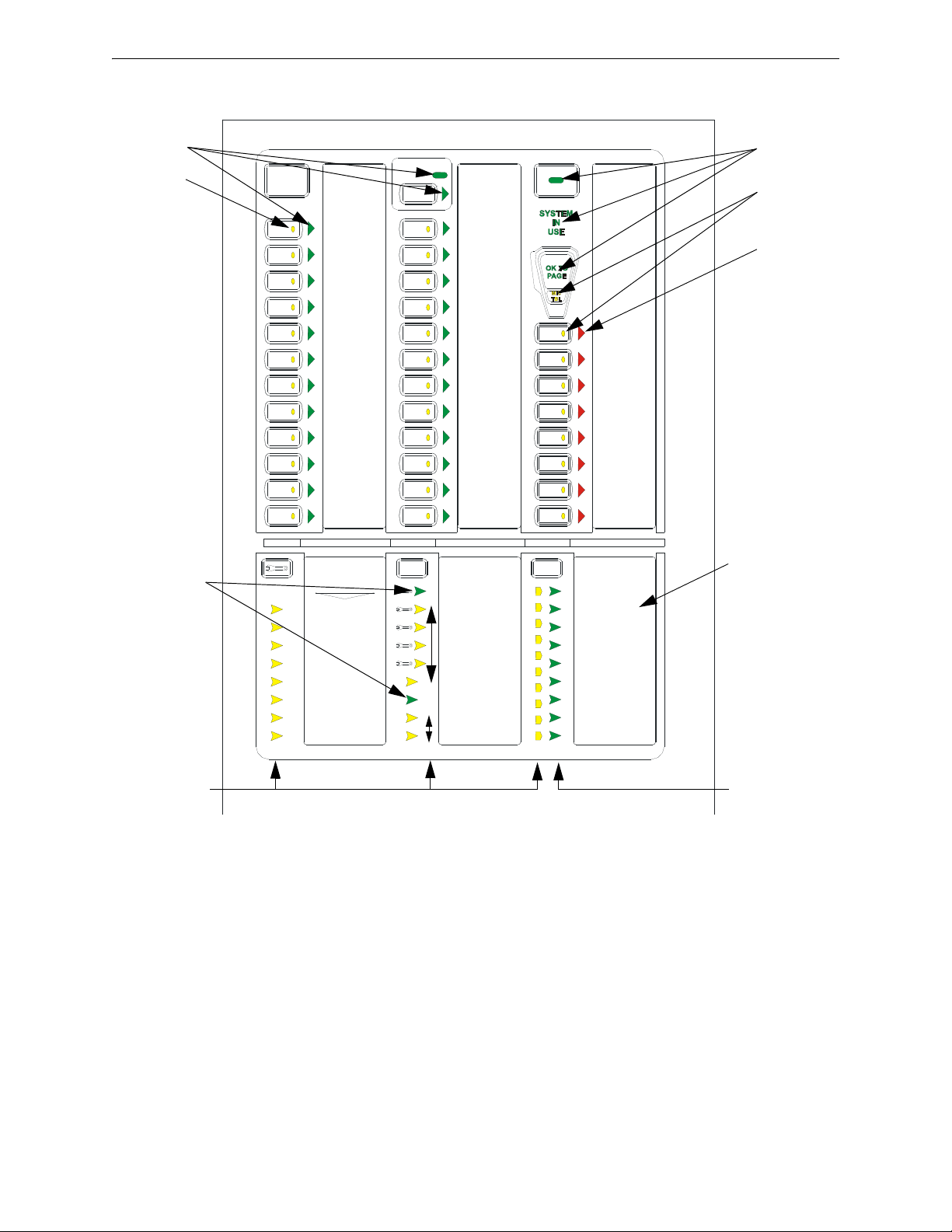
Figure 1.4 ECC-50/100 Keypad
SPEAKER
ZONE 1
SPEAKER
ZONE 2
SPEAKER
ZONE 3
SPEAKER
ZONE 4
SPEAKER
ZONE 5
SPEAKER
ZONE 6
SPEAKER
ZONE 7
SPEAKER
ZONE 8
SPEAKER
ZONE 9
SPEAKER
ZONE 10
SPEAKER
ZONE 11
SPEAKER
ZONE 12
SPEAKER
ZONE 13
SPEAKER
ZONE 14
SPEAKER
ZONE 15
SPEAKER
ZONE 16
SPEAKER
ZONE 17
SPEAKER
ZONE 18
SPEAKER
ZONE 19
SPEAKER
ZONE 20
SPEAKER
ZONE 21
SPEAKER
ZONE 22
SPEAKER
ZONE 23
SPEAKER
ZONE 24
MESSAGE 1
MESSAGE 2
MESSAGE 3
MESSAGE 4
MESSAGE 5
MESSAGE 6
MESSAGE 7
MESSAGE 8
DIST. AMP 1
DIST. AMP 2
DIST. AMP 3
DIST. AMP 4
DIST. AMP 5
DIST. AMP 6
DIST. AMP 7
DIST. AMP 8
DIAGNOSTIC
REMOTE AMPS
TROUBLE SILENCE
AC POWER
GROUND FAULT
CHARGER FAULT
BATTERY FAULT
DATA BUS FAULT
NAC FAULT
NAC ACTIVE
SYSTEM TROUBLE
AUDIO RISER FAULT
LOC 1
LOC 2
RPU 1
RPU 2
RPU 3
RM 1
RM 2
RM 3
CONSOLE LAMP TEST
MAIN CONSOLE
MNS
CONTROL
OK TO PAGE
MICROPHONE
TROUBLE
green green
yellow
yellow
red
green
green
yellow
Note: Console
assignments are
shown here as an
example only.
1.3 Controls and Indicators
1.3.1 Push-Button Controls
•All Call
• MNS Control
• System Control
• Speaker Select 1-24
• Message Select 1-8
• Diagnostic Select
• Trouble Silence
•Console Lamp Test
20 Emergency Command Center Manual — P/N LS10001-000FL-E:D 9/3/2014
Page 21

Components Product Description
1.3.2 LED Indicators (visible with door closed)
• Fire System Active (green)
• MNS Control (green)
• System Control (green)
• System in Use (green)
• Speaker Zone 1-24 Active (green)
• Speaker Zone 1-24 Fault (yellow)
• OK to Page (green)
• Microphone Trouble (yellow)
• Message 1-8 Active (red)
• Message 1-8 Fault (yellow)
• Remote Amplifier 1-8 Fault (yellow)
• LOC/RPU/RM 1-8 Fault (yellow)
• LOC/RPU/RM 1-8 Active (green)
• Main Console Fault (yellow)
• AC Power (green)
• Ground Fault (yellow)
• Charger Fault (yellow)
• Battery Fault (yellow)
• Data Bus Fault (yellow)
• NAC Fault (yellow)
• NAC Active (green)
• System Trouble (yellow)
• Audio Riser Fault (yellow)
1.3.3 LED Indicators (visible with door and dress panel open)
• Speaker Volume Control Fault (yellow)
• Option Card Fault (yellow)
• Amplifier Over Current Fault (yellow)
1.4 Components
Main Control Board
The ECC-50/100 main control board contains the system's CPU, power supply, battery charger,
other primary components and wiring interface components. One 50W amplifier is integrated into
the main control board.
Display Board
The display board contains the user interface along with tone generators, digital message
recorder/generator, integral microphone input, and preamplifier.
Emergency Command Center Manual — P/N LS10001-000FL-E:D 9/3/2014 21
Page 22
Product Description Components
FIRE SYSTEM
ACTIVE
SYSTEM
CONTROL
ALL
CALL
1
2
3
4
5
6
7
8
9
10
11
12
13
18
19
20
21
22
23
24
16
17
14
15
LIT
FI®AL
by Honeywell
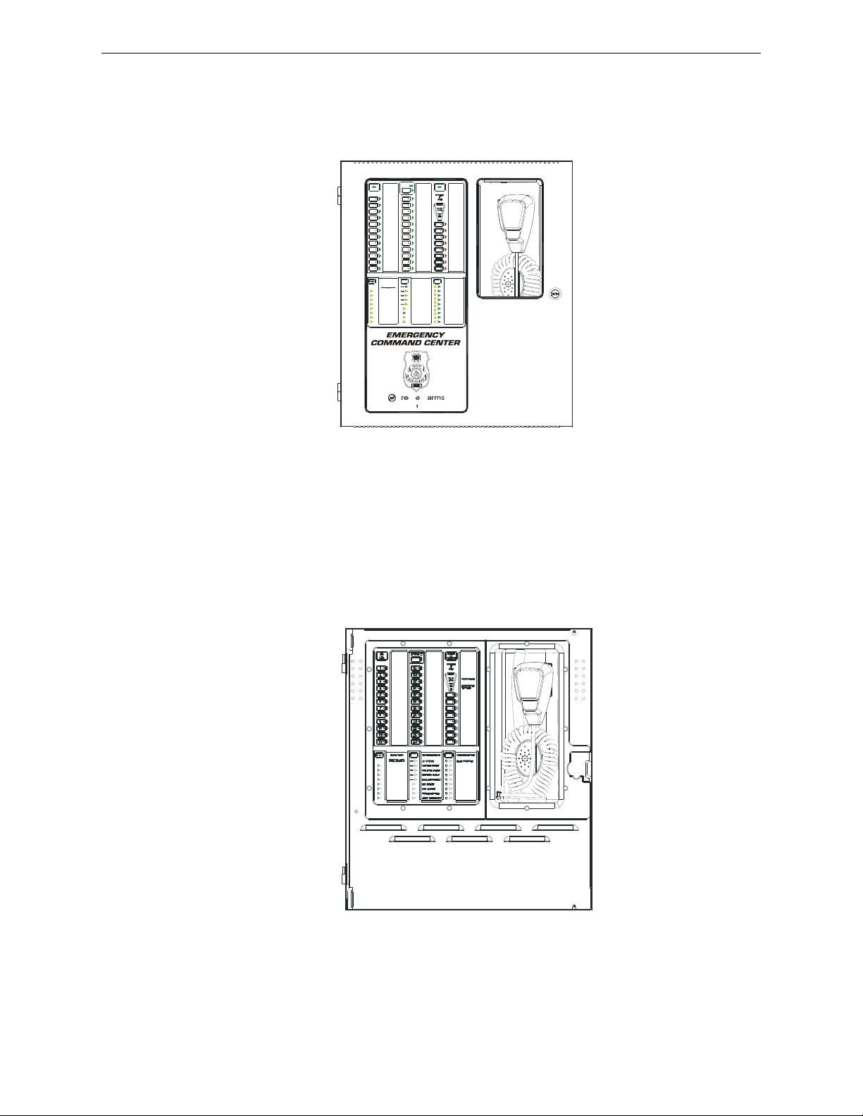
Figure 1.5 Cabinet
eccfront.wmf
Figure 1.6 Dress Panel
ecc_dp.wmf
Cabinet
The cabinet is red with an attractive navy blue front overlay. A clear window allows viewing of the
display board, status LEDs and location of microphone. The backbox measures 16.65" x 19.0" x
5.2" D (42.29cm x 48.26cm x 13.23cm) and provides space for two 12AH or two 18AH batteries.
Batteries
The cabinet provides space for up to 18 Amp Hour batteries (charged by integral Power Supply/Battery Charger) with all options installed.
Dress Panel
The Dress Panel is supplied standard with the system. It mounts to the cabinet with two supplied
screws. The Dress Panel protects the user from high voltages and circuit boards from accidental
damage.
Trim Ring
An optional TR-CE trim ring is available for semi-flush mounting of the audio pa nel.
22 Emergency Command Center Manual — P/N LS10001-000FL-E:D 9/3/2014
Page 23

Optional Equipment Product Description
1.5 Optional Equipment
ECC-50W-25/70V Audio Amplifier Modules
An optional second audio amplifier can be plugged into connectors J10 & J11 located in the upper
right of the main control board in the ECC-50/100. This amplifier also provides 50 watts of power
RMS
or 70 V
at 25 V
to 100 watts (providing dual 50 watt speaker circuits) or it can be used as a backup amplifier. The
output is power-limited (Class 2) and speaker circuit connections to it are provided on the main
control board and optional speaker circuit expander module. The circuit can be wired for Style Y
(Class B) or Style Z (Class A) operation.
LEDs are provided to indicate Amplifier Supervision (green indicates amplifier is functional) and
Circuit Trouble (yellow indicates field wiring fault or amplifier fault). The LEDs are only visible
with the panel door open.
ECC-CE6 Circuit Expander Module
This optional module plugs into connector P1 in the upper middle of the main control board. The
ECC-CE6 adds three primary speaker circuits to the ECC-50/100. The ECC-CE6 adds three secondary circuits to the system when the ECC-50W-25/70V Audio Amplifier Module is also
installed.
, depending on the model, and can therefore be used to expand system power
RMS
ECC-XRM-70V Transformer 70.7 V
RMS
This optional module plugs into connector J12 of the main control board and provides conversion
for the integral audio amplifier from 25 V
to 70.7 V
RMS
at full rated 50 watts output power.
RMS
ECC-FFT Fire Fighter Telephone
The ECC-FFT has a telephone handset and user interface that allows an operator to communicate
with remotely located telephone handsets in a building. It is housed in its own cabinet with key
lock. It requires an external operator interface power connection (24 volts DC) from the ECC50/100 main console or it may be powered from an external 24 VDC power supply such as
HP300ULX. The ECC-FFT provides supervision, annunciation, and control for the local handset
and for up to 24 remote telephone handsets. It provides indications of phone activation and corresponding trouble conditions. Refer to the ECC-FFT Fire Fighter T elephone manual. Not for use in
UL2572 Mass Notification or Canadian applications.
ECC-50DA Distributed (Remote) Audio
The ECC-50DA is a 50-watt audio amplifier (audio booster) with its own cabinet and key lock. It
requires an external data bus connection and an external audio riser connection from the ECC50/100 main console. The unit comes standard with 4 speaker circuits. An option card, ECC-CE4,
provides 4 more speaker circuits for a total of 8. Speaker circuits are activated/de-activated manually or automatically by the ECC-50/100 main console. The unit is capable of either 25 V
70.7 V
operation. Refer to the ECC-50/125DA Distributed Audio manual. Not for use in Cana-
RMS
RMS
or
dian applications.
ECC-125DA Distributed (Remote) Audio
The ECC-125DA is a 125-watt audio amplifier (audio booster) with its own cabinet and key lock. It
requires an external data bus connection and an external audio riser connection from the ECC50/100 main console. The unit comes standard with four (4) speaker circuits. An option card, ECCCE4, provides 4 more speaker circuits for a total of eight (8). Speaker circuits are activated/de-activated manually or automatically by the ECC-50/100 main console. The unit is capable of 25 V
RMS
operation. Refer to the ECC-50/125DA Distributed Audio manual. Not for use in Canadian applications.
ECC-50BDA Distributed (Remote) Audio
The ECC-50BDA is a 50/100-watt audio amplifier (audio booster) with its own cabinet and key
lock. It requires an external data bus connection and an external audio riser connection from the
ECC-50/100 main console. The ECC-50BDA is capable of producing up to 100 watts of audio
Emergency Command Center Manual — P/N LS10001-000FL-E:D 9/3/2014 23
Page 24

Product Description UL 464 Low Frequency Sounders
power. The amplifier functions as 50 watts with 50 watts as backup, 100 watts with no backup or
100 watts with 50 watts backup using ECC-50WBU. The unit comes standard with 8 speaker circuits. Speaker circuits are activated/de-activated manually or automatically by the ECC-50/100
main console. The unit is capable of either 25 V
RMS
or 70.7 V
operation. Refer to the ECC Dis-
RMS
tributed Audio manual. Not for use in Canadian applications.
NOTE: Any combination of up to eight audio boosters comprised of ECC-50DA, ECC-125DA,
and ECC-50BDA can be used in the system. Their external data bus addresses must be unique
and must be sequential. Addresses are set via dipswitches on each unit's PC board. Refer to
Section 2.14 on page 55.
ECC-RM Remote Microphone
The ECC-RM has a hand held microphone and is housed in its own cabinet with keyed lock. It
requires an external data bus connection, an external audio riser connection, and an external operator interface power connection (24 volts DC) from the ECC-50/100 main console. ALL CALL paging can be broadcast over the speaker circuits by depressing the microphone's push-to-talk switch.
Not for use in UL2572 Mass Notification or Canadian applications.
ECC-RPU Remote Page Unit
The ECC-RPU has a hand held microphone and 8 message buttons. It is housed in its own cabinet
with a keyed lock or thumb lock (requires AHJ approval). It also has a 9th button that will activate
an MMF-300 monitor module mounted inside the cabinet. This may be used for HVAC shutdown
applications when the monitor module is connected to the FACP SLC polling loop. The remote
page unit requires an external data bus connection, an external audio riser connection, and an external operator interface power connection (24 volts DC) from the ECC-50/100 main console. ALL
CALL paging can be broadcast over the speaker circuits by depressing the microphone's push-totalk switch. ALL CALL broadcast of a stored message can be done by pressing a message button.
The message buttons operate in the same fashion as the message buttons on the ECC-50/100 main
console. Not for use in UL2572 Mass Notification or Canadian applications.
ECC-LOC Local Operator Console
The ECC-LOC has a complete operator interface like the ECC-50/100 main console and is housed
in its own cabinet with a keyed lock or thumb lock (requires AHJ approval). The local operator
console requires an external data bus connection, an external audio riser connection, and an external operator interface power connection (24 volts DC) from the ECC-50/100 main console.
NOTE: Any combination of up to eight remote consoles comprised of ECC-RM(s), ECC-RPU(s),
and ECC-LOC(s) can be used in the system. Their external data bus addresses must be set via
dip switches on each unit's PC board. Refer to Section 2.14 on page 55.
1.6 UL 464 Low Frequency Sounders
This product complies with the requirements for a low frequency sounder (520Hz) as specified in
UL 464 when used as part of a system with the following items.
Amplifiers:
Amplifier/Audio Product Description
ECC-50/100 Main console
ECC-50/100 with ECC-50W-25V Main console with optional second 25V amplifier installed
ECC-50/100 with ECC-XRM-70V Main console with 70V transformer installed
ECC-50/100 with ECC-XRM-70V
and ECC-50W-70V
Main console with 70V transformer and optional second 70V
amplifier installed
24 Emergency Command Center Manual — P/N LS10001-000FL-E:D 9/3/2014
Page 25

UL 464 Low Frequency Sounders Product Description
Audio File:
The 520 Hz audio file is available for download at Firelite.com.
Speakers:
For a complete list of speakers that can be used in an Emergency Command Center system with the
above specifications, refer to the current version of the Device Compatibility document, p/n 15384.
Emergency Command Center Manual — P/N LS10001-000FL-E:D 9/3/2014 25
Page 26

Section 2: Installation
!
2.1 Mounting Options
The cabinet may be semi-flush or surface mounted. The cabinet mounts using three key slots at the
top of the backbox and two additional 0.250" diameter holes located at the bot tom .
Carefully unpack the system and check for shipping damage. Mount the cabinet in a clean, dry,
vibration-free area where extreme temperatures are not encountered. The area should be readily
accessible with sufficient room to easily install and maintain the panel. Locate the top of the cabinet approximately five feet above the floor with the hinge mounting on the left. Determine the
number of conductors required for the devices to be installed. Sufficient knockouts are provided
for wiring convenience. Select the appropriate knockout(s) and pull the required conductors into
the box. Note that knockouts are also located on the back of the cabinet. All wiring should be in
accordance with the National and/or Local codes for fire alarm systems. Refer to Figure 2.4 for
knockouts that cannot be used.
2.2 Backbox Installation
CAUTION: STATIC SENSITIVE COMPONENTS
THE CIRCUIT BOARD CONTAINS STATIC-SENSITIVE COMPONENTS. ALWAYS GROUND
YOURSELF WITH A PROPER WRIST STRAP BEFORE HANDLING ANY BOARDS SO THAT
STATIC CHARGES ARE REMOVED FROM THE BODY. USE STATIC SUPPRESSIVE PACKAGING TO PROTECT ELECTRONIC ASSEMBLIES.
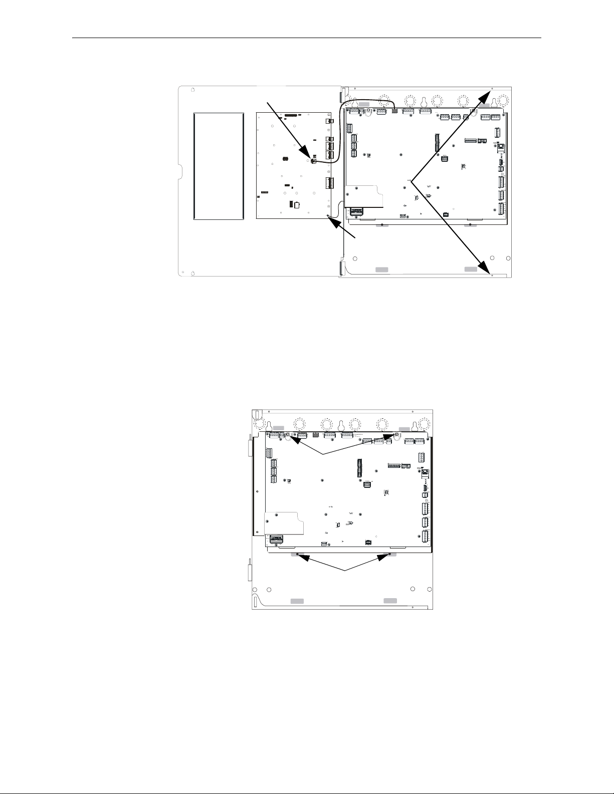
Removing the Dress Panel
1. Open the door and lift the door off the pin hinges.
2. Loosen the two (2) screws that secure the dress panel to the backbox. Then, lift up to swing
the dress panel open.
3. Disconnect the ground wire from the dress panel.
4. Unplug the cable on the display board at J2. This is the connection to the main control board on
the chassis.
26 Emergency Command Center Manual — P/N LS10001-000FL-E:D 9/3/2014
Page 27
Backbox Installation Installation
J12
TB15
J9
RTZM
Rev.
ECC-MCB-PCA
loosen screws
disconnect
earth ground
unplug cable
lift up dress panel,
pull out,
slide down to remove
Figure 2.1 Dress Panel Removal
ecc-dpopn.wmf
remove screws
loosen nuts
chassisinst.wmf
Figure 2.2 Chassis Removal
5. Lift the dress panel up and gently pull the lower hinge out of the backbox. Gently pull down to
remove the top hinge. Store the dress panel in a safe place.
Removing the Chassis Assembly
1. If present, remove the two (2) screws which fasten the lower chassis tabs to the backbox.
These are for shipping purposes only and do not need to be reinstalled.
2. Loosen the two nuts which secure the top of the chassis with an 11/32” socket.
3. Carefully lift up and remove the chassis assembly from the backbox and store in a safe, clean
place. Avoid static discharge which may damage static sensitive components on the board.
Emergency Command Center Manual — P/N LS10001-000FL-E:D 9/3/2014 27
Page 28
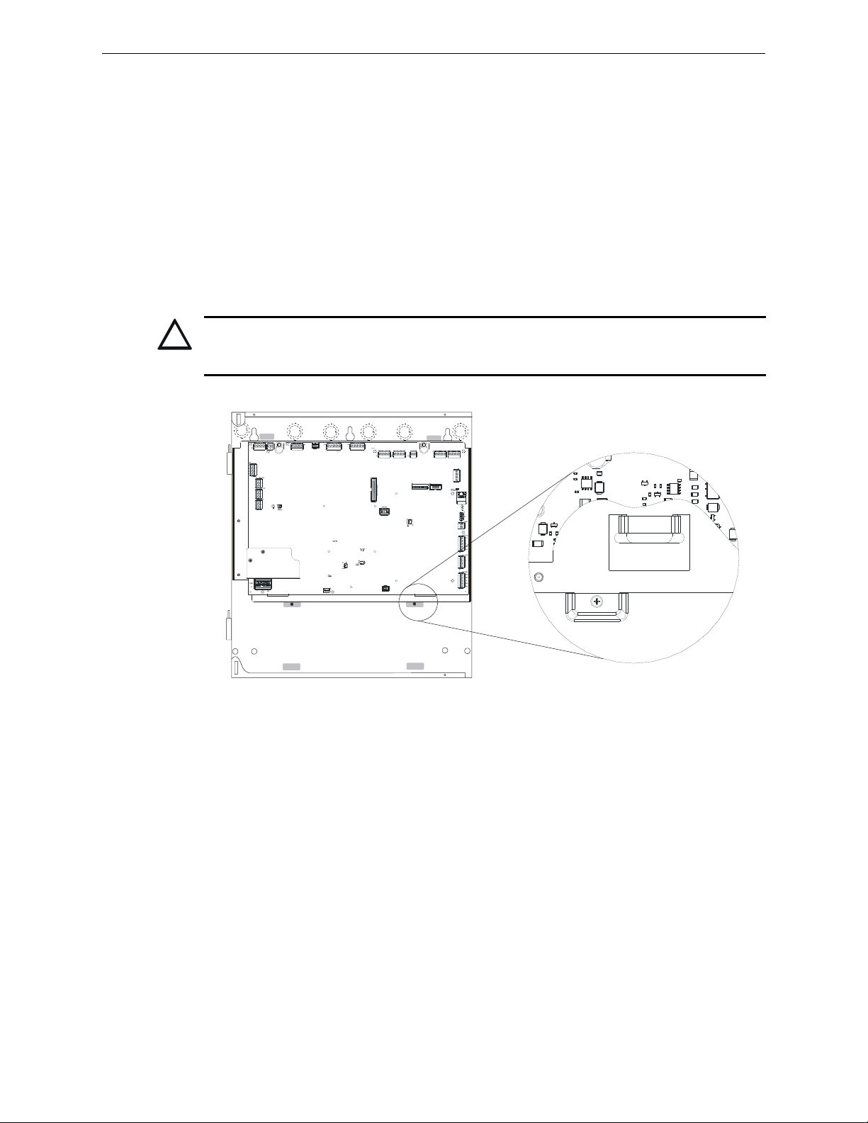
Installation Backbox Installation
!
J12
TB15
J9
RTZM
Rev.
ECC-MCB-PCA
Figure 2.3 Chassis Installation
chassistab.wmf
Mounting the Backbox
1. Mark and predrill hole in the wall for the center top keyhole mounting bol t us ing the dimensions illustrated in Figure 2.4 on page 29.
2. Install center top fastener in the wall with the screw head protruding.
3. Place backbox over the top screw, level and secure.
4. Mark and drill the left and right upper and lower mounting holes.
Note: Outer holes (closest to sidewall) are used for 16” O.C. stud mounting.
5. Install remaining fasteners and tighten.
6. Carefully reinstall the chassis assembly and dress panel by reversing the steps above. Use
appropriate precautions to prevent damage to components due to static discharge. When
reinstalling the chassis assembly , be s ure that all four (4) tabs are seated properly in the slots of
the backbox to avoid possible damage to the unit.
CAUTION: POSSIBLE EQUIPMENT DAMAGE
REINSTALL THE CHASSIS ASSEMBLY CAREFULLY, MAKING SURE TO PROPERLY SEAT THE
UNIT TO THE BACKBOX.
7. Draw wires through the respective knockout locations.
An optional Trim Ring (P/N TR-CE) is available for semi-flush mount installations.
28 Emergency Command Center Manual — P/N LS10001-000FL-E:D 9/3/2014
Page 29
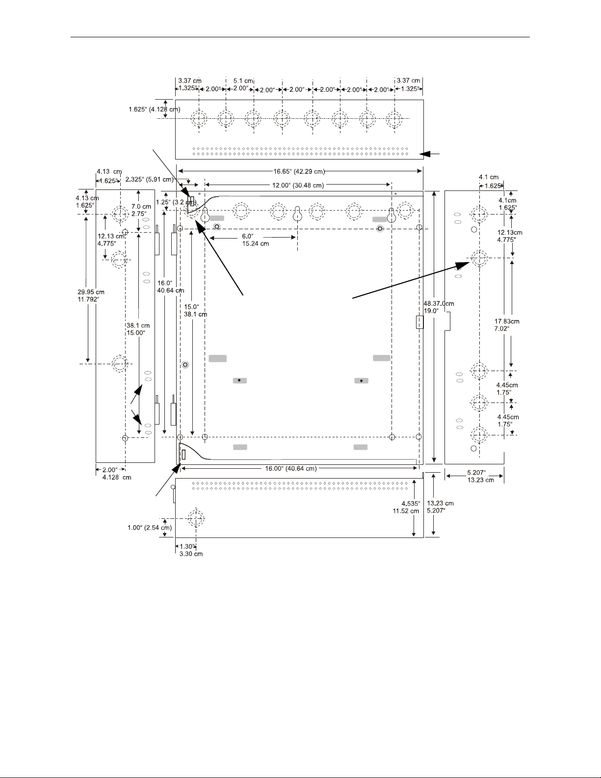
Backbox Installation Installation
Figure 2.4 Cabinet Dimensions & Knockout Locations
9050udencl.wmf
Semi-Flush Mounting
Do not recess box more
than 3.875” into wall to
avoid covering venting
holes on top of box.
Hinge Slot for
Dress Panel
Hinge Slot for
Dress Panel
Semi-flush
mounting hole
Mounting
slots for
optional
Trim Ring
Do not use these knock-outs!
Emergency Command Center Manual — P/N LS10001-000FL-E:D 9/3/2014 29
Page 30
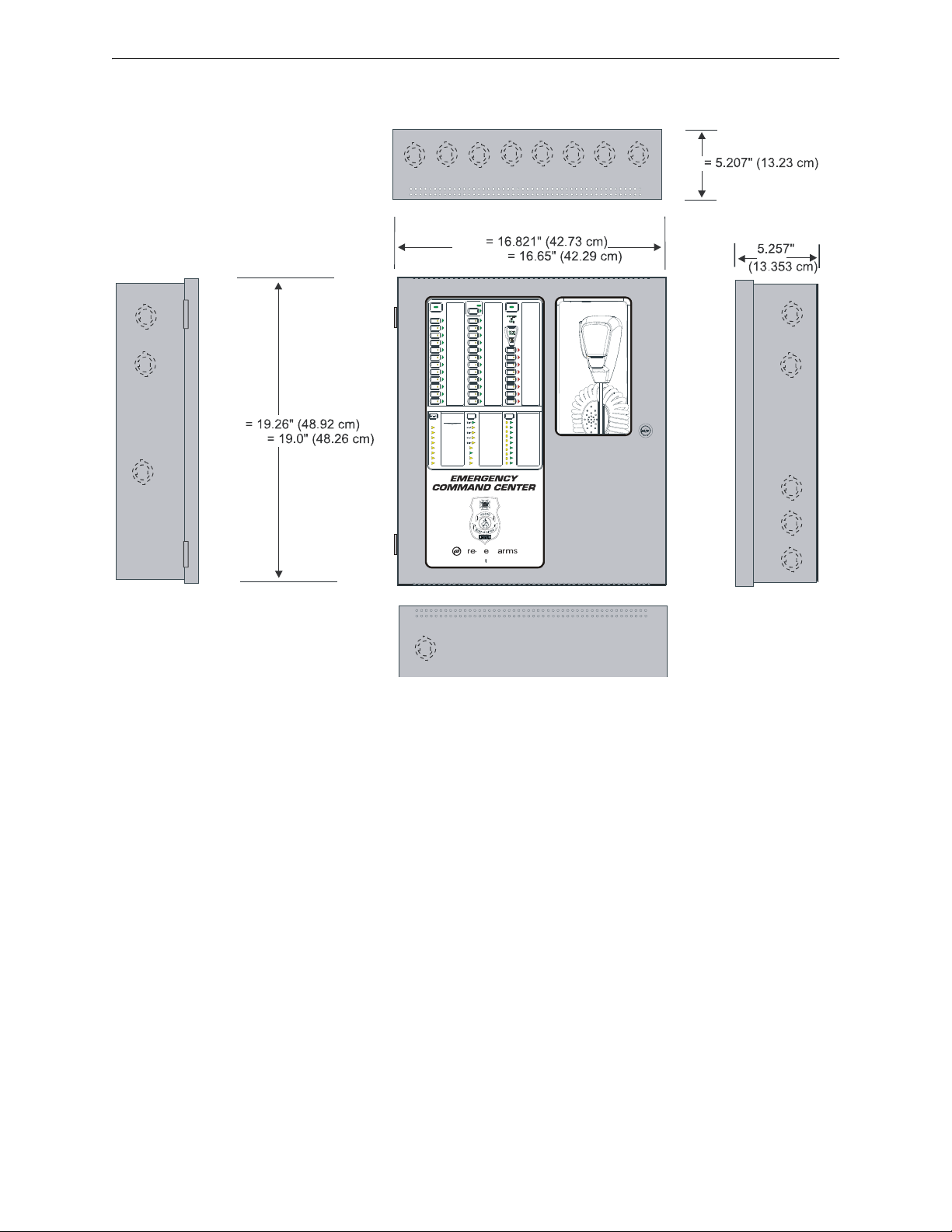
Installation Backbox Installation
FIRE SYSTEM
ACTIVE
SYSTEM
CONTROL
ALL
CALL
1
2
3
4
5
6
7
8
9
10
11
12
13
18
19
20
21
22
23
24
16
17
14
15
LIT
FI
®
AL
by Honeywell
Figure 2.5 ECC-50/100 Backbox Dimensions
ecc-cab.wmf
Left Side
Right Side
Bottom
Door
Door
Backbox
Backbox
Depth =
Depth
Top
30 Emergency Command Center Manual — P/N LS10001-000FL-E:D 9/3/2014
Page 31

Operating Power Installation
!
Figure 2.6 Earth Ground Connection
e
c
c
g
n
d
.
w
m
f
grounding stud
keps nuts
Grounding
Cable #71073
grounding stud
Equipment
Ground
2.3 Operating Power
WARNING: RISK OF EQUIPMENT DAMAGE AND PERSONAL INJURY
SEVERAL DIFFERENT SOURCES OF POWER CAN BE CONNECTED TO THIS PANEL. DISCONNECT ALL SOURCES OF POWER BEFORE SERVICING. THE PANEL AND ASSOCIATED
EQUIPMENT MAY BE DAMAGED BY REMOVING AND/OR INSERTING CARDS, MODULES OR
INTERCONNECTING CABLES WHILE THIS UNIT IS ENERGIZED. BE SURE TO OBSERVE
PROPER GROUNDING AND HANDLING PROCEDURES.
2.3.1 AC Power and Earth Ground Connection
Primary power source for the ECC-50/100 is 120 VAC, 60 Hz, 3.5 amps. Primary power source for
the ECC-50/100E is 240 VAC, 50 Hz, 2.0 amps. Over-current protection for this circuit must comply with Article 760 of the National Electrical Code (NEC) and/or local codes. Make certain that
the AC mains circuit breaker is off before making any wiring connections between the mains and
the panel. Connect AC mains wiring from the protected premises main breaker box to TB15 of the
main control board. Use 14 AWG (2.0 mm2, 1.6 mm O.D.) or heavier gauge wire with 600V insulation. No other equipment may be connected to this circuit and it may not contain any power disconnect devices. A separate Earth Ground connection must be made to ensure proper panel
operation and lightning and transient protection. Do not use conduit for the Earth Ground connection since this does not provide reliable protection. Remove the two keps nuts from the grounding
stud in the backbox. Connect the incoming earth ground wire to supplied cable #71073 with a wire
nut. Position the ring terminal end over the grounding stud. Secure with one of th e keps nuts.
Place the ring terminal from the other supplied cable to TB15. Refer to Figure 2.6 for the location
of the stud. Apply AC power to the panel only after the system is completely installed and visually
checked. Note that AC power must be applied to the panel before installing the battery intercon-
nect cable (refer to the following section).
Emergency Command Center Manual — P/N LS10001-000FL-E:D 9/3/2014 31
Page 32

Installation Operating Power
-
-
+
+
Interconnect
Cable
!
Figure 2.7 Operating Power Connections
e
c
c
p
o
w
e
r
.
w
m
f
VAC
Hot (black)
Ground (green)
Neutral (white)
Connect Earth
Ground wire to
ground stud with
grounding cable
black (-)red (+)
18 AH
battery
18 AH
battery
2.3.2 Secondary Power Source (Batteries)
The batteries must be sealed lead acid type. Before connecting the batteries to the FACP, make certain that the
interconnect cable between the batteries is not
Do not connect the interconnect cable until the system is
completely installed.
WARNING: RISK OF PERSONAL INJURY
BATTERY CONTAINS SULFURIC ACID WHICH CAN CAUSE SEVERE BURNS TO THE SKIN
AND EYES AND CAN DESTROY FABRICS. IF CONTACT IS MADE WITH SULFURIC ACID,
IMMEDIATELY FLUSH THE SKIN OR EYES WITH WATER FOR 15 MINUTES AND SEEK IMMEDIATE MEDICAL ATTENTION.
Observe polarity when connecting the batteries. Connect the battery cable to J7 on the main control
board, using the plug-in connector and cable provided. The battery charger is current-limited and
capable of recharging sealed lead acid type batteries (See Figure 2.7 for battery orientation). The
charger shuts off when the system is in alarm. See page 93 for calculation of the correct battery rating.
connected.
32 Emergency Command Center Manual — P/N LS10001-000FL-E:D 9/3/2014
Page 33

Auxiliary DC Power Output Connections Installation
TB17
Special Application Power (500 mA @ 24 VDC) is nonresettable power suitable
for powering control modules and End-of Line Power supervision relays.
See Device Compatibility Document for compatible devices.
Figure 2.8 Auxiliary Power Connection
e
c
c
t
b
1
7
.
w
m
f
Figure 2.9 Command Input Circuits
Style Z (Class A)
FACP ELR
(for Style Y - Class B only)
NAC reverse polarity trigger
(alarm polarity shown)
Class B (Style B) Contact Closure trigger input, such as
an emergency signaling manual pull station (MNS only).
(4.7K, 1/2 watt EOL Resistors P/N: 71252)
ECC-50/100 Main Control Board
e
c
c
t
b
4
.
w
m
f
alarm polarities shown
Host FACP
NAC
TB4
CMD1
TB5
CMD2
TB6
CMD3,4
TB7
CMD5,6
TB8
CMD7,8
2.4 Auxiliary DC Power Output Connections
The Special Application Auxiliary DC power output is power-limited (Class 2).
2.5 Input/Initiating Circuits
2.5.1 CMD Inputs
The ECC-50/100 has eight Command Input circuits, which are used to activate the panel amplifiers
which, in turn, transmit an audio signal over the system speakers. All field wiring for the circuits is
power-limited (Class 2) and supervised for opens and ground faults. Note that zero impedance to
ground will cause a ground fault.
CMD1 and CMD2 Command Input circuits can be independently field programmed to be triggered
by a contact closure or by the reverse polarity of a Notification Appliance Circuit.
IMPORTANT! When CMD1 and CMD2 are configured for reverse polarity , the NAC cannot
Coded (including NAC Sync).
CMD1 has internal relay contacts before the out terminals which will open the outgoin g NAC circuit during an ECC-50/100 trouble condition (AC loss is programmable as described in Section 3).
This causes a NAC trouble at the host FACP. Note that CMD1 and CMD2 configurations can be
independently set so that both circuits are triggered by the same type of input or by different types
of inputs (see Figure 2.9 below).
be
Emergency Command Center Manual — P/N LS10001-000FL-E:D 9/3/2014 33
Page 34

Installation Input/Initiating Circuits
-++ -
+ -
Figure 2.1 Addressable Module Connections
24 VDC
(EOLR-1) EOL Power
Supervision Relay
Note 2
SLC
SLC
Note 3
Special Application
Power- Note 1
Note 3
4.7 K ELRs
P/N 27072
Control
Module
Monitor
Module
Output
e
c
c
m
o
d
s
.
w
m
f
CMD3, CMD4, CMD5, CMD6, CMD7, and CMD8 Command Input circuits are triggered by a
contact closure only. Each Command input will activate various messages and amplifiers depending on the Message Control selection configured in user programming (refer to Section 3).
NOTE: CMD8 cannot be used when the system is programmed to provide more than eight (8)
messages.
When configured with a compatible, addressable FACP, the ECC-50/100 may be triggered either
by the FACP main NAC output or from addressable control modules. Figure 2.1 illustrates CMD1
triggered by an addressable control module. The addressable control module may trigger the ECC50/100 via reverse polarity (shown) or relay contact. The FACP monitors the ECC-50/100 for
faults while in the standby or alarm state by wiring a monitor module to the trouble contacts as
shown in Figure 2.1. Activation of the addressable control module is controlled by the FACP.
Refer to the appropriate FACP manual for additional information.
Notes:
1. 24 VDC Auxiliary Power terminals for special application power only. W iring must remain in
2. Supervise the wiring between the ECC-50/100 Auxiliary Power output and the control module
3. End-of-Line resistor supplied with modules.
the room.
with an EOL relay (EOLR-1).
2.5.2 External Audio Input
The display provides connection to various ancillary sources. See Sections 2.5.4 on page 35, 3.4.2
on page 71, and 4.4.15 on page 91 for more information.
34 Emergency Command Center Manual — P/N LS10001-000FL-E:D 9/3/2014
Page 35

Input/Initiating Circuits Installation
from FACP NAC (or NAC Follower
output) or previous device
to next device
4.7K ELR needed for
last device in chain.
alarm polarity shown
TB18
1 2 3 4
Figure 2.10 NAC Follower Wiring
ECC-50/100 Main Control Board
e
c
c
t
b
1
8
.
w
m
f
+ -
PBX
audio out
external audio input
GND
In
contact
closure output
TB5 on display
board
TB16 on main
control board
e
c
c
t
b
1
6
.
w
m
f
Figure 2.11 Night Ring Wiring
2.5.3 NAC Follower Input
For fire-only applications, the NAC follower input may be used to trigger the onboard NAC.
Strobes driven by the onboard NAC must be visibly isolated from FACP NAC(s).
This can be accomplished by connecting the NAC Follower input at TB18 of the control board to
the FACP's NAC output. The ECC-50/100 NAC output will then follow the FACP's NACs. A
redundant pair of terminals is provided at TB18 for convenient connection of an EOL resistor, or
for wiring to any additional equipment requiring this feature (such as an FCPS-FS6/8 remote power
supply).
The NAC Follower input is power-limited (Class 2) (refer to Section 2.12, “UL Power-limited W iring Requirements”, on page 49) and supervised by th e ho st FACP. Supervision requires that a
4.7 K EOL resistor be connected to the last device in the NAC Follower chain.
2.5.4 Night Ring
The external audio input allows a building’s Private Branch Exchange (PBX) to activate the ECC50/100. Connections need to be made to TB16 on the main control board and to TB5.1 and TB5.2
on the display board. Refer to Section 1.2.2 for electrical specifications to the external audio input.
Emergency Command Center Manual — P/N LS10001-000FL-E:D 9/3/2014 35
Page 36
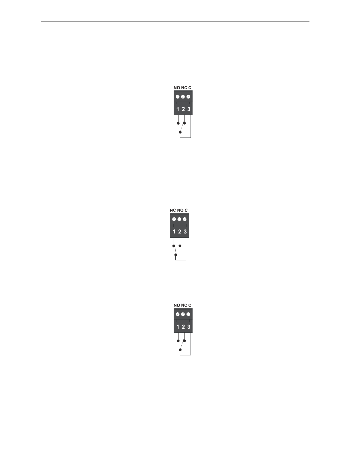
Installation Output Circuits
Figure 2.12 MNS Active Relay
TB1
e
c
c
a
c
r
l
.
w
m
f
Shown in normal,
Inactive condition
Figure 2.13 Trouble Relay
TB2
e
c
c
t
r
b
l
.
w
m
f
Shown in energized,
non trouble condition
Figure 2.14 AC Power Loss Relay
TB3
Shown in normal
AC Power condition
e
c
c
a
c
r
l
.
w
m
f
2.6 Output Circuits
2.6.1 Relays
MNS Active Relay - TB1
The main control board provides a Form-C MNS Active relay.
Trouble Relay - TB2
The main control board provides a Form-C Trouble relay for independent, general system fault
monitoring. This relay is ‘fail safe’, meaning that it is normally energized. Should system power
shut off, this relay will de-energize, transferring its contacts. The Trouble Relay can be programmed to track the AC Loss Relay and transfer on AC loss conditions or ignore AC loss conditions.
AC Power Loss Relay - TB3
The main control board provides a Form-C AC Power Loss relay.
36 Emergency Command Center Manual — P/N LS10001-000FL-E:D 9/3/2014
Page 37

Output Circuits Installation
!
TB20
TB21
Figure 2.15 Speaker Circuit Connections
Style Z (Class A) Circuit
ELR required for
Style Y - Class B only
15K, 1 watt, P/N:ELR-15K
Shield
e
c
c
c
k
t
1
.
w
m
f
2.6.2 Speaker Circuits
• One Speaker Circuit Style Y (Class B) or Style Z (Class A) standard
• Two Speaker Circuits Style Y (Class B) or Style Z (Class A) with ECC-50-25/70V
• Four Speaker Circuits Style Z (Class B) or Style Z (Class A) or Style Y with ECC-CE6
• Eight Speaker Circuits Style Z (Class B) or Style Z (Class A) or St yle Y with ECC-50W25/70V and ECC-CE6
The integral amplifier and optional amplifier each provide audio for one Speaker Circuit. The circuit can be wired Style Y (Class B) or Style Z (Class A). Each supervised and power-limited
(Class 2) circuit is capable of 50 watts of power. Refer to the Fire•Lite Device Compatibility Document for a listing of compatible speakers.
CAUTION: OBSERVE POLARITY
MATCH PROPER POLARITY CONNECTIONS TO FIELD WIRING AND SPEAKERS. POLARITY
SHOWN IS IN THE STANDBY AND ALARM CONDITIONS.
Shielded cable is not required, however, shielded cable will reduce RFI/EMI emissions and susceptibility. For additional information, refer to “Wiring Requirements” on page 98.
Emergency Command Center Manual — P/N LS10001-000FL-E:D 9/3/2014 37
Page 38

Installation Output Circuits
+
+
+
ELR, 4.7K, 1/2W (for
Class B/Style Y wiring)
TB19
Polarized Bell
Polarized Strobe
Polarized Horn
Figure 2.16 NAC Wiring - Style Y (Class B)
e
c
c
n
a
c
.
w
m
f
+
+
+
TB19
Polarized Bell
Polarized Strobe
Polarized Horn
Figure 2.17 NAC Wiring - Style Z (Class A)
e
c
c
n
a
c
a
.
w
m
f
2.6.3 Notification Appliance Circuit
The ECC-50/100 provides a Style Y (Class B) or Style Z (Class A) NAC (Notification Appliance
Circuit). Use UL-listed 24 VDC visual notification appliances only. Circuit is supervised and
power-limited (Class 2). Refer to the Fire•Lite Device Compatibility Document for a listing of
compatible notification appliances.
38 Emergency Command Center Manual — P/N LS10001-000FL-E:D 9/3/2014
Page 39

Output Circuits Installation
SPKR AMP DC DC
+ - + - + - + -
}
}
}
}
102345678
9
10
}
+
-
+ -
+
-
From preceding volume control module
or override output (on main board)
To next speaker (variable volume)
From audio output or preceding
speaker (fixed volume)
To next volume control module or ELR
SP-SVC
SP-SVC terminal layout
Variable Volume
Speakers
Fixed Volume Speakers
15K, 1W ELR
P/N: ELR-15K
4.7K, 1/2W ELR
P/N: 71252
Figure 2.18 Speaker Volume Control Wiring
TB23 on ECC-50/100
main control board
From Speaker
Circuit Output
e
c
c
t
b
2
3
.
w
m
f
s
p
-
s
v
c
w
i
r
e
.
w
m
f
2.6.4 Speaker Volume Control
Speaker Volume Control requires use of the Cooper Wheelock SP-SVC module. The Supervised
Volume Control (SP-SVC) allows manual volume setting for telephone paging and background
music for a specific speaker or speaker zone. The selected adjustment will not affect the volume
setting of emergency prerecorded messages or live microphone usage. Refer to the Cooper Whee-
lock Safepath SP-SVC Installation Instructions (P/N: P84598) for more information.
Notes:
1. Only one (1) SP-SVC can be installed per audio zone; however, multiple speakers can be
controlled by the same speaker volume control override output.
2. All fixed volume speakers must be placed before the SP-SVC in the speaker circuit. Any
speakers placed after the SP-SVC module will be able to be attenuated.
3. An end-of-line resistor (ELR) must be installed on the last speaker connected to the SP-SVC.
4. Attach wires according to the label on the terminal block. The DC input/output terminals are
interchangeable. If the SP-SVC is the last unit in the Speaker Volume Control Override circuit,
then an ELR must be installed.
5. The maximum wire impedance between devices must not exceed 35 ohms.
Emergency Command Center Manual — P/N LS10001-000FL-E:D 9/3/2014 39
Page 40

Installation Output Circuits
Figure 2.19 Connection for MS-9600(UD)LS to ECC-50/100
MS-9600(UD)LS
ECC-50/100
to other ACS/ANN
devices
A B
ANN
ACS
9
6
0
0
e
c
c
.
w
m
f
+ -
B+ A+ B- A- A B
ACS
SHIELD
SLC
SLC
SLC
SLC
OUT+ IN+ OUT- IN-
TB8
TB9
TB10
Figure 2.20 Connection for MS-9200UDLS to ECC-50/100
MS-9200UDLS
ECC-50/100
to other ACS/ANN
devices
A B
ANN
ACS
9
2
0
0
u
d
e
c
c
.
w
m
f
2.6.5 FACP Data Bus
MS-9600(UD)LS
The F ACP communicates with the ECC-50/100 over the ACS or ANN-BUS annunciator link. Wiring must be connected between T erminal TB6 on the FACP and Terminal TB13 on the ECC-50/100
panel.
MS-9200UDLS
The MS-9200UDLS FACP communicates with the ECC-50/100 over the ACS or ANN-BUS
annunciator link. Wiring must be connected between Terminal TB9 on the FACP and Terminal
TB13 on the ECC-50/100 panel.
40 Emergency Command Center Manual — P/N LS10001-000FL-E:D 9/3/2014
Page 41

Output Circuits Installation
SLC
TB1 MNS Active Relay
monitor
module
Figure 2.21 Monitor Module Wiring for ACS Communication
a
c
s
m
o
n
i
t
o
r
.
w
m
f
ACS Mode Wiring
When communication is wired over the ACS annunciator link, a monitor module must be used to
monitor mass notification events. Wire the monitor module to the ECC at TB1 MNS Active Relay
in addition to the Data Bus wiring shown above. Refer to the FACP manual for information on type
IDs.
Emergency Command Center Manual — P/N LS10001-000FL-E:D 9/3/2014 41
Page 42

Installation ECC-LOC Local Operator Console
!
J12
TB15
J9
RTZM
Rev.
ECC-MCB-PCA
B
A
+--
+
-
+
BA+
-
+
-+-BABA
ECC-50/100
main control board
ECC-LOC
display board
TB24
TB12
TB22
TB3
TB4
TB5
external operator interface
power - 24VDC
external data bus
external
audio riser
to next operator
interface or amplifier
(or, if last device,
signal termination
ELR-15K)
to next
operator
interface or
amplifier
l
o
c
w
i
r
e
b
2
.
w
m
f
Figure 2.22 Local Operator Console Wiring (Class B/Style Y)
TB2
JP2
(shown jumpered
on pins 2 and 3)
2.7 ECC-LOC Local Operator Console
CAUTION: EXTERNAL WIRING CONNECTIONS
THE ECC-LOC IS A SEPARATE DEVICE, NOT PART OF THE ECC-50/100 ASSEMBLY!
Wiring for the Local Operator Console is accomplished between TB24, TB12, and TB22 on the
ECC-50/100 main control board to TB3, TB4, and TB5 on the LOC. If the ECC-LOC is the last
device on the audio and data bus chain, signal terminations are required. For the external data bus,
a removable jumper must be on pins 1 and 2 of JP2 when the LOC is the last device on the chain.
If the ECC-LOC is not the last device, the jumper must be on pins 2 and 3 of JP2 as shown below.
For the external audio riser, when the LOC is the last device, termination ELR-15K must be connected to pins 5 and 6 on TB5. T-taps and multip le hom e runs to the main control board are not
allowed for the external data bus or the external data riser.
42 Emergency Command Center Manual — P/N LS10001-000FL-E:D 9/3/2014
Page 43

ECC-LOC Local Operator Console Installation
J12
TB15
J9
RTZM
Rev.
ECC-MCB-PCA
BA+--+-+BA+
-
+
-+-BABA
TB24
TB12
TB22
TB3
TB4
TB5
external operator interface
power - 24VDC
external data bus
external
audio riser
l
o
c
w
i
r
e
a
2
.
w
m
f
Figure 2.23 Local Operator Console Wiring (Class A/Style Z)
TB2
JP2
(shown jumpered
on pins 2 and 3)
ECC-50/100
main control board
ECC-LOC
display board
Emergency Command Center Manual — P/N LS10001-000FL-E:D 9/3/2014 43
Page 44

Installation ECC-RPU Remote Page Unit
+
-
+
-
+
-
+
-
+
-
+
-
B
A
B
A
B
A
main control board
RPU board
TB24
TB12
TB22
TB1
TB3
TB2
external operator interface power - 24VDC
external
data bus
external
audio
riser
to next operator
interface or amplifier
r
p
u
w
i
r
e
b
.
w
m
f
Figure 2.24 Remote Page Unit Wiring (Class B/Style Y)
to next operator
interface or amplifier
to next operator
interface or amplifier
JS4
(shown jumpered
on pins 2 and 3)
2.8 ECC-RPU Remote Page Unit
Connections are made from TB24, TB12, and TB22 on the EC C-50/100 main control board to
TB1, TB3, and TB2 on the RPU. If the ECC-RPU is the last device on the audio and data bus
chain, signal terminations are required. For the external data bus, a removable jumper must be on
pins 1 and 2 of JS4. If the ECC-RPU is not the last device, the jumper must be on pins 2 and 3 of
JS4 as shown below. For the external audio riser, when the ECC-RPU is the last device, termination ELR-15K must be connected to pins 4 and 5 on TB2. T-taps and multiple home runs to the
main control board are not allowed for the external data bus or the external data riser.
44 Emergency Command Center Manual — P/N LS10001-000FL-E:D 9/3/2014
Page 45

ECC-RPU Remote Page Unit Installation
+ -
B
A
B
A
B
A
B
A
+
-
+
-
+
-
+
-
+
-
main control board
RPU board
TB24
TB12
TB22
TB1
TB3
TB2
external operator interface power - 24VDC
external
data bus
external
audio
riser
r
p
u
w
i
r
e
a
.
w
m
f
Figure 2.25 Remote Page Unit Wiring (Class A/Style Z)
JS4
(shown jumpered
on pins 2 and 3)
Emergency Command Center Manual — P/N LS10001-000FL-E:D 9/3/2014 45
Page 46

Installation ECC-RM Remote Microphone
+
-
+
-
+
-
+
-
B
A
A
B
+
-
+
-
A
B
main control board
RM board
TB24
TB12
TB22
TB3
data bus
TB2
audio out
TB1
power
external operator
interface power -
24VDC
external data bus
external
audio
riser
to next operator
interface or amplifier
r
m
w
i
r
e
b
.
w
m
f
Figure 2.26 Remote Microphone Wiring (Class B/Style Y)
JS4
(shown jumpered
on pins 2 and 3)
+
+
-
+
-
+
-
B
A
B
A
A
B
A
B
+
-
+
-
main control board
RM board
TB24
TB12
TB22
TB3
data bus
TB2
audio out
TB1
power
external operator
interface power -
24VDC
external
data
bus
external
audio
riser
r
m
w
i
r
e
a
.
w
m
f
Figure 2.27 Remote Microphone Wiring (Class A/Style Z)
JS4
(shown jumpered
on pins 2 and 3)
2.9 ECC-RM Remote Microphone
Connections are made from TB24, TB12, and TB22 on the EC C-50/100 main control board to
TB3, TB2, and TB1 on the RM. If the ECC-RM is the last device on the audio and data bus chain,
signal terminations are required. For the external data bus, a removable jumper must be on pins 1
and 2 of JS4. If the ECC-RM is not the last device, the jumper must be on pins 2 and 3 of JS4. For
the external audio riser, For the external audio riser, when the ECC-RM is the last device, termination ELR-15K must be on pins 4 and 5 on TB2. T-taps and multiple home runs to the main control
board are not allowed for the external data bus or the external data riser.
46 Emergency Command Center Manual — P/N LS10001-000FL-E:D 9/3/2014
Page 47

ECC-50DA, ECC-125DA, ECC-50BDA Distributed Audio Amplifiers Installation
ECC-50/100
ECC-50/100
ECC-RM
ECC-RPU
ECC-LOC
ECC-50DA
ECC-125DA
ECC-50BDA
Class B
(Style Y)
Class A
(Style Z)
External Data Bus or
External Audio Riser
External Data Bus or
External Audio Riser
Figure 2.28 Shielding for One External Device
s
h
l
d
s
i
n
g
l
e
.
w
m
f
ECC-RM
ECC-RPU
ECC-LOC
ECC-50DA
ECC-125DA
ECC-50BDA
2.10 ECC-50DA, ECC-125DA, ECC-50BDA Distributed Audio Amplifiers
SW2 on the ECC-50/100’s display board must be set to the UP position if any remote audio boosters are installed on the system. Refer to the ECC Distributed Audio Amplifier Manual, LS10027000FL-E, for installation instructions.
2.11 Shielding for External Device Wiring
The external data bus and external audio riser circuits must be wired using twisted pair cable.
Shielded cable is optional but is recommended for sites with electric machinery, electric motors,
etc. to minimize the effects of electrical interference. Do not run either cable adjacent to or in the
same conduit as 120 VAC service, noisy electrical circuits that are powering mechanical bells or
horns, speaker circuits, motor control circuits or SCR power circuits. External operator interface
power (24VDC) may be run adjacent to or in the same conduit as the external data bus and external
audio riser circuits.
At the ECC-50/100 unit, the cable shields must be connected to the same connectors where the signals originate. If only one external device (i.e. an ECC-RM) is used in the system, the shield in the
external device must be left floating. It must not touch anything. If multiple external devices are
used in the system then the shields must “pass through” (connect to the outgoing shield using wire
nuts without touching anything else). For Class A (Style Z) installations, the shield from the last
external operator interface must be connected to the same ECC-50/100 terminal that the shield
originated from.
NOTE: Never use a cable shield as an enclosure's earth ground. The EIA-485 shield is for
radiated noise emission protection (RFI, EMI).Refer to the following illustrations for details on
shield termination.
Emergency Command Center Manual — P/N LS10001-000FL-E:D 9/3/2014 47
Page 48

Installation Shielding for External Device Wiring
ECC-50/100
ECC-50/100
Class B
(Style Y)
Class A
(Style Z)
External
Data Bus or
External
Audio Riser
External Data Bus or
External Audio Riser
Figure 2.29 Shielding for Multiple External Devices
“pass through”
“pass through”
s
h
l
d
m
u
l
t
i
.
w
m
f
ECC-RM
ECC-RPU
ECC-LOC
ECC-50DA
ECC-125DA
ECC-50BDA
ECC-RM
ECC-RPU
ECC-LOC
ECC-50DA
ECC-125DA
ECC-50BDA
48 Emergency Command Center Manual — P/N LS10001-000FL-E:D 9/3/2014
Page 49

UL Power-limited Wiring Requirements Installation
Figure 2.30 Typical Wiring Diagram for UL Power-limited Requirements
Power-limited Circuits
(Class 2)
e
c
c
u
l
p
w
r
.
w
m
f
Power-limited Circuits
(Class 2)
Power-limited
Circuits
(Class 2)
AC Power
Nonpower-
limited Circuit
Power-limited
Circuits
(Class 2)
Power-limited
Circuits
(Class 2)
to batteries
nonpower-
limited circuit
Power-limited
Circuits
(Class 2)
2.12 UL Power-limited Wiring Requirements
Power-limited and nonpower-limited circuit wiring must remain separated in the cabinet. All
power-limited circuit wiring must remain at least 0.25" away from any nonpower-limited circuit
wiring. Furthermore, all power-limited and nonpower-limited circuit wiring must enter and exit the
cabinet through different knockouts and/or conduits. A typical wiring diagram for the ECC-50/100
with two speaker circuits is shown below.
NOTE: Use of the 70V transformer makes all power-limited circuits Class 3.
Emergency Command Center Manual — P/N LS10001-000FL-E:D 9/3/2014 49
Page 50

Installation Installation of Option Modules
!
Rev.
ECC-MCB-PCA
Figure 2.31 Circuit Expander Module Wiring
Style Z (Class A) Circuit
ELR required for Style Y Class B only
15K, 1 watt, P/N:ELR-15K
Shield
c
e
6
w
i
r
e
.
w
m
f
ECC-CE6 mounted onto ECC-50/100
2.13 Installation of Option Modules
CAUTION: DISCONNECT POWER
BEFORE INSTALLING ANY MODULES OR CABLES, MAKE CERTAIN ALL POWER (AC AND DC)
HAS BEEN REMOVED AND BE SURE TO OBSERVE PROPER GROUNDING AND HANDLING
PROCEDURES.
2.13.1 ECC-CE6 Circuit Expander Module
The ECC-CE6 Circuit Expander Module provides connections for up to six Style Z (Class A) or
Style Y (Class B) speaker circuits. Circuits are configured through the web-based programming
utility. Refer to Section 3.1.2 on page 61.
50 Emergency Command Center Manual — P/N LS10001-000FL-E:D 9/3/2014
2.13.2 Audio Amplifier Module (ECC-50W-25/70V)
Installation
The optional audio amplifier module can be used to provide a second 50 watt speaker circuit,
increasing the total ECC-50/100 power to 100 watts, or it can be used as a backup amplifier. Refer
to Section 3.1.2 on page 61 for programming the amplifier’s operation. Connectors J1 & J2 of the
audio amplifier module plug into connectors J10 & J11, respectively, located at the upper right of
the main control board.
Figure 2.33 shows the installation of a ECC-50W-25/70V onto an ECC-50/100 panel. The optional
amplifier may be programmed and wired for backup or for providing a second audio channel.
NOTE: Both the primary and secondary amplifiers must be same voltage output (25V or 70V).
1. Remove mounting screws shown, from the main control board, and save (refer to Figure 2.33).
2. Install four supplied metal standoffs in locations from which mounting screws were removed
in Step 1.
3. Secure the Audio Amplifier Module with the screws removed in Step 1. It is important to
secure the module with the metal screws in order to help protect against electrical transients.
Page 51

Installation of Option Modules Installation
J12
TB15
J9
+-
RTZM
Rev.
ECC-MCB-PCA
Figure 2.32 Installation of the Optional Audio Amplifier
ECC-50W-25/70V
ECC-50/100
main control board
b
d
a
m
n
t
.
w
m
f
LED4 - Fault
LED2 - Limit
LED3 - Enabled
SW4 - Fail Test Switch
SW7 - 35W - NOT USED
SW6 - 50W
SW5 - 75W
(Not populated on 70V boards) -
NOT USED
LED1 - Power
BDA
Power
BDA
Control
Connect J1 to J10
Connect J2 to J11
4. Plug the supplied power cable into J10 on the main control board, then into J1 on the audio
amplifier. Plug the supplied control cable into J11 on the main control board, then into J2 on
the audio amplifier.
5. Configure the slide switches, SW6 and SW7, per Figure 2.35. Do not use any other setting.
6. Configure the slide switch, SW5, on the main control board for 25V or 70V operation. (70V
operation requires Amplifier model ECC-50W-70V and the ECC-XRM-70V transformer.)
7. Connect field wiring to TB21 on the main control board (if not using the amplifier as backup).
Refer to Figure 2.15 on page 37 for illustration of speaker connections if the amplifier is being
used to expand system power to 100 watts (providing dual 50 watt speaker circuits).
8. Configure the Audio Amplifier for primary or backup amplifier operation through the webbased programming utility.
Emergency Command Center Manual — P/N LS10001-000FL-E:D 9/3/2014 51
Page 52

Installation Installation of Option Modules
J12
TB15
J9
RTZM
Rev.
ECC-MCB-PCA
P1
J12
TB15
J9
+-
RTZM
Rev.
ECC-MCB-PCA
1. Attach four
standoffs (p/n
42227) at
locations
indicated.
2. Align
amplifier over
standoffs.
Attach with four
screws.
3. Attach power
harnesses
(included with
amplifier - refer
to Figure 2.34):
Power and
Control Harness
Connections
Amplifier
Main Control Board
• J1 on amplifier to J10 on ECC
• J2 on amplifier to J11 on ECC
J2
J1
J10
J11
Figure 2.33 ECC-50W-25/70V Installation
e
c
c
5
0
.
w
m
f
b
d
a
m
n
t
.
w
m
f
Control cable
p/n 75690
Align tab with notch in
board connector.
Tab
Power cable
p/n 75689
Align cable connectors
over spaces and pins.
Align where
there is no pin.
Figure 2.34 Control and Power Cables
Figure 2.35 Enable Switches
SW6 is shown enabled.
Do not enable.
Figure 2.36 FAIL TEST Switch
Power and Control Cables
Configuration
52 Emergency Command Center Manual — P/N LS10001-000FL-E:D 9/3/2014
Enable Switches, SW6 & SW7
SW6 must be enabled. Do not enable SW7.
Switches come from the factory disabled.
Note that the board is installed upside-down.
Pay close attention when setting switches.
Figure 2.35 shows the amplifier in its installed
position, not the actual silk-screening on the
board.
FAIL TEST Switch, SW4
This switch is not used. It should always be set
to “Normal”.
Page 53
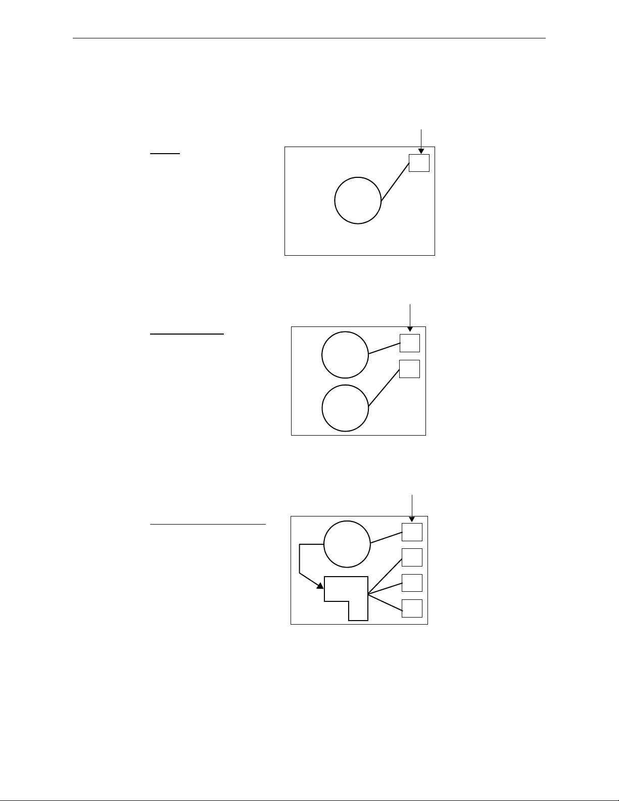
Installation of Option Modules Installation
50W
circuit
1
Primary
• 50W
• One Class B or Class A Output
• No Backup
Figure 2.37 Basic (No Optional Amplifier)
Primary
TB20 on main control board
Speaker Circuit Connection
zone button
50W
circuit
1
Primary/Secondary
• Two amps at 50W each
• Two Class B or Class A Outputs
• Optional amplifier is the secondary
• No Backup
Primary
50W
amp
Secondary
Figure 2.38 Primary/Secondary
2
TB20 on main control board
TB21 on main control board
Speaker Circuit Connections
zone button
50W
circuit
1
2
3
4
Primary with Circuit Expander
• 50W
• Four Class B or Class A Outputs
• ECC-CE6 adds 3 speaker circuits
• No backup
Primary
shares
50W
CE6
Figure 2.39 Primary with Expander
TB20 on main control board
TB1 on ECC-CE6
TB2 on ECC-CE6
TB3 on ECC-CE6
Speaker Circuit Connections
zone button
ECC-50/100 Configurations with ECC-50W-25/70V
Following are descriptions of audio speaker circuit configurations with option a l amplifier and
optional ECC-CE6 circuit expander.
Applications Without Backup
Emergency Command Center Manual — P/N LS10001-000FL-E:D 9/3/2014 53
Page 54

Installation Installation of Option Modules
50W
circuit
1
2
3
4
Primary/Secondary with Expander
and Optional Amplifier
• 50W for primary, 50W for secondary
• Eight Class B or Class A Outputs
• Optional amplifier supplies all
secondary circuits
• ECC-CE6 adds 3 primary and 3
secondary circuits
• No backup
Primary
50W
amp
Secondary
Figure 2.40 Primary/Secondary with Expander and Optional Amplifier
CE6
5
6
7
8
TB20 on main control board
TB21 on main control board
TB1 on ECC-CE6, primary power
TB4 on ECC-CE6, secondary power
TB2 on ECC-CE6, primary power
TB5 on ECC-CE6, secondary power
TB3 on ECC-CE6, primary power
TB6 on ECC-CE6, secondary power
Speaker Circuit Connections
zone button
50W
circuit
1
Primary with Backup
• One amp at 50W
• One Class B or Class A Output
• Optional amplifier is the backup
Primary
50W
amp
Backup
Figure 2.41 Primary with Optional Amplifier Backup
TB20 on main control board
Speaker Circuit Connections
zone button
50W
circuit
1
2
3
4
Primary with Expander and Backup
• 50W for primary, 50W for backup
• Four Class B or Class A Outputs
• ECC-CE6 adds 3 primary speaker
circuits
• Optional Amplifier is the backup
Primary
Figure 2.42 Primary with Expander and Optional Amplifier Backup
CE6
Primary/
Backup
50W
amp
Backup
TB20 on main control board
TB1 on ECC-CE6
TB2 on ECC-CE6
TB3 on ECC-CE6
Speaker Circuit Connections
zone button
Applications With Backup
54 Emergency Command Center Manual — P/N LS10001-000FL-E:D 9/3/2014
Page 55

Addressing External Data Bus Devices Installation
Figure 2.43 70.7 V
RMS
Transformer Installation
ECC-CE6
e
c
c
x
f
m
r
c
e
6
.
w
m
f
!
2.13.3 70.7 V
The 70.7 V
where 70.7 V
supervised during standby, alarm and while background music is playing when transformer is
installed. The transformer comes pre-installed onto a bracket for mounting to the chassis. Installation onto the chassis depends on what other option modules are installed. See the ECC-XRM-70V
Installation Document. Refer to the drawing below.
Transformer (ECC-XRM-70V)
RMS
Transformer can be used to convert the integral 25 V
RMS
speakers already exist or are to be installed. Speaker wiring continues to be
RMS
amplifier for installations
RMS
NOTE: For 70.7V
operation with the optional amplifier, use model ECC-50W-70V.
RMS
CAUTION: DISCONNECT POWER
BEFORE INSTALLING ANY MODULES, MAKE CERTAIN ALL POWER (AC AND DC) HAS BEEN
REMOVED.
When installing the ECC-XRM-70V, be sure to:
carefully remove the factory-installed jumper plug from connector J12 on the main control
board.
set SW5 on the ECC-50/100 main control bo ard to 70V operation.
2.14 Addressing External Data Bus Devices
The table below defines an address map for the external data bus devices which include the
ECC-LOC, ECC-RPU, ECC-RM, ECC-50DA, and ECC-125DA. Dipswitches are used on each of
these devices to set the bus address in order to properly communicate with the ECC-50/100 panel.
Any combination of up to eight (8) remote consoles (ECC-LOC, ECC-RPU, and ECC-RM) can be
Emergency Command Center Manual — P/N LS10001-000FL-E:D 9/3/2014 55
Page 56

Installation Addressing External Data Bus Devices
5 4 3 2 1
ON
5 4 3 2 1
ON
1 2 3 4 5
ON
used in the system. Their external data bus addresses must be unique. Note that these four (4) consoles occupy two (2) data bus addresses each. The second address is already “reserved” in the system for each console. Up to eight (8) distributed amplifiers (ECC-50DA and ECC-125DA) can be
used in the system. Their external data bus addresses must also be unique and sequential. All
addressing must also be set in user programming. Refer to Section 3.1.3 on page 63.
Table 2.1 below shows the dipswitch settings for all possible addresses. Note that some devices
have a 5-position dipswitch while others have a 6-position dipswitch. The sixth switch on these
dipswitches are not used. Dipswitches are shown as they are oriented in the cabinet. Pay close
attention when setting addresses.
Dipswitch Setting
on LOC (SW1)
Bus Address Device
0 reserved n/a n/a n/a
1 reserved n/a n/a n/a
2 reserved n/a n/a n/a
3 reserved n/a n/a n/a
4 LOC or RPU or RM #1
5 reserved n/a n/a n/a
6 LOC or RPU or RM #2
7 reserved n/a n/a n/a
8 LOC or RPU or RM #3
9 reserved n/a n/a n/a
10 LOC or RPU or RM #4
Dipswitch Setting
on RPU (S11)
Dipswitch Setting
on RM (S1)
11 reserved n/a n/a n/a
12 LOC or RPU or RM #5
13 reserved n/a n/a n/a
14 LOC or RPU or RM #6
15 reserved n/a n/a n/a
16 LOC or RPU or RM #7
17 reserved n/a n/a n/a
18 LOC or RPU or RM #8
19 reserved n/a n/a n/a
56 Emergency Command Center Manual — P/N LS10001-000FL-E:D 9/3/2014
Page 57

Addressing External Data Bus Devices Installation
1
2
3
4
5
6
ON
1
2
3
4
5
ON
1
2
3
4
5
6
7
8
ON
1
2
3
4
5
6
ON
1
2
3
4
5
ON
1
2
3
4
5
6
7
8
ON
1
2
3
4
5
6
ON
1
2
3
4
5
ON
1
2
3
4
5
6
7
8
ON
1
2
3
4
5
6
ON
1
2
3
4
5
ON
1
2
3
4
5
6
7
8
ON
1
2
3
4
5
6
ON
1
2
3
4
5
ON
1
2
3
4
5
6
7
8
ON
1
2
3
4
5
6
ON
1
2
3
4
5
ON
1
2
3
4
5
6
7
8
ON
Bus Address Device
20 External Amp #1
21 External Amp #2
22 External Amp #3
Dipswitch Setting on
ECC-50DA(SW1)
Dipswitch Setting on
ECC-125DA (SW1)
Dipswitch Setting on
ECC-50BDA (SW3)
23 External Amp #4
24 External Amp #5
25 External Amp #6
Table 2.1 External Data Bus Dipswitch Settings
Emergency Command Center Manual — P/N LS10001-000FL-E:D 9/3/2014 57
Page 58

Installation Addressing External Data Bus Devices
1
2
3
4
5
6
ON
1
2
3
4
5
ON
1
2
3
4
5
6
7
8
ON
1
2
3
4
5
6
ON
1
2
3
4
5
ON
1
2
3
4
5
6
7
8
ON
Bus Address Device
26 External Amp #7
27 External Amp #8
Table 2.1 External Data Bus Dipswitch Settings
Dipswitch Setting on
ECC-50DA(SW1)
Dipswitch Setting on
ECC-125DA (SW1)
Dipswitch Setting on
ECC-50BDA (SW3)
58 Emergency Command Center Manual — P/N LS10001-000FL-E:D 9/3/2014
Page 59

Section 3: Programming
NOTICE TO USERS, INSTALLERS, AUTHORITIES HAVING JURISDICTION
AND OTHER INVOLVED PARTIES
This product incorporates field-programmable software. In order for the product to comply with the requirements in the Standard
for Control Units and Accessories for Fire Alarm Systems, UL 864, and in the standard for Communication and Control Units for
Mass Notification Systems, UL 2572, certain programming features or options must be limited to specific values or not used at all
as indicated below:
Program feature
or option
Permitted in
UL 864/UL 2572?
(Y/N)
Possible settings
Settings permitted in
UL 864/UL 2572
AC Loss Delay Y AC Loss Delay = 0, 2 (factory default), 6, 12, or 23 hours
Refer to “AC Loss Delay” on page 62.
24 Hour Resound Y 24 Hour Resound = Enabled
24 Hour Resound = Disabled
Refer to “24 Hour Resound” on page 61
All ECC programming is done using the built-in web-based programming utility. It is recommended that tone selection, message repeat cycles and background music options be reviewed and
approved by the local AHJ.
To start programming, use a standard CAT5e Ethernet cable to connect a personal computer’s IP
port (Ethernet) to the IP port (Ethernet) J2 on the main control board (right side of the board). Set
the computer’s local area network connection address as follows:
IP address: 169.254.3.5
Subnet mask: 255.255.0.0
NOTE: Be sure to record the computer’s original addresses so they can be restored when ECC
programming is complete.
Activate the PC’s web browser (Microsoft Internet Explorer version 8 or Mozilla Firefox). Enter
the following in the browser’s navigation bar:
http://169.254.3.3
The main menu will display and allow further menu navigation.
AC Loss Delay = 2 hours
24 Hour Resound
Enabled
NOTE: All screen shots reflect default programming.
Security and Data Protection:
NO ENCRYPTION EMPLOYED
• Communication Security:
– a. Level 1
• Stored Data Security:
– a. Level 0
• Access Control Security:
– a. Level 1
• Physical Security:
– a. Level 1
Audit Control: not provided
Emergency Command Center Manual — P/N LS10001-000FL-E:D 9/3/2014 59
Page 60

Programming Main Menu - User Programming
Figure 3.1 Main Menu
m
a
i
n
_
m
e
n
u
.
j
p
g
Figure 3.2 Password Options
3.1 Main Menu - User Programming
This screen shows the main menu for the ECC user programming options. Changes to programming require a valid password for system login. Note that a password is NOT required to change
the date/time, view the informational screens, or view the panel history.
3.1.1 Password Options
Changes to ECC programming require a valid password login. Programming changes cannot be
made when there is an active event in the system.
Log In Password The default password for the ECC-50/100 is 0000.
New Password It is recommended that the password be changed to increase system security.
Valid passwords contain four digits from 0000-9999.
Verify New Password Re-enter the new password for confirmation.
Inactivity Timeout Select the amount of time, 5 minutes, 10 minutes, 20 minutes, 30 minutes, or
60 minutes, the system is allowed to remain idle before automatic user log out. The timeout feature
helps the system protect against unauthorized programming changes.
60 Emergency Command Center Manual — P/N LS10001-000FL-E:D 9/3/2014
Page 61

Main Menu - User Programming Programming
Figure 3.3 General Options
g
e
n
e
r
a
l
o
p
2
.
j
p
g
Log Out When all programming has been successfully completed, the user must log out to allow
the system to reboot and apply the programming changes.
3.1.2 General/NAC Options
General Options
Unit Operation Select whether the ECC will function for Fire Evacuation, Mass Notification, or
a Combination of both.
Event Priority When Combo or Mass Notification is selected for Unit Operation, select whether
Mass Notification events or Fire Evacuation events will take priority in the system. If Mass Notification is selected as the Unit Operation with the Event Priority set to Fir e Evacuation, the ECC will
be a mass notification only system but will allow the FACP to override it if a fire alarm sounds. If
Mass Notification is selected as the Unit Operation with the Event Priority also set to Mass Notification, the ECC will not have any fire evacuation capabilities and will report mass notification
events to the FACP. In this configuration, FACP outputs can be turned off for mass notification
events if desired.
FACP Data Bus Control If an FACP will directly communicate with the ECC, select which
communication protocol will be used, ACS-Bus or ANN-Bus.
FACP Data Bus Address This field has no effect on programming and is used for informational purposes only. When using the FACP ACS-bus protocol, address 01 must be enabled in the
FACP programming. When using the ANN-Bus protocol, the FACP will automatically detect the
audio system connection during annunciator auto-configuration. No ANN-Bus address selection is
necessary at the FACP. Enter the ECC’s address (1-8) here. If FACP control of the ECC is not
selected, enter 0.
24 Hour Resound As enabled (default), the 24 Hour Resound feature causes the piezo on the
ECC to sound a reminder ‘beep’ for alarms and troubles after the panel has been silenced.
Canadian Configuration Selecting enable will configure the panel to comply with Canadian
requirements. See Appendix C for more information.
Class A / Style Z Select enable if all circuits on the ECC will operate in Class A (Style Z) or dis-
abled if all circuits will operate in Class B (Style Y).
Canadian Isolator Modules If audio isolator modules are required in the system, select
enabled. Refer to “Audio Room Isolator Modules” on page 99 for more information.
Emergency Command Center Manual — P/N LS10001-000FL-E:D 9/3/2014 61
Page 62

Programming Main Menu - User Programming
Figure 3.4 NAC Options
n
a
c
o
p
t
i
o
n
s
2
.
j
p
g
AC Loss Delay The reporting of a loss of AC power using the AC Loss relay output can be
delayed by programming the length of the desired delay. The factory default setting is 2 hours.
Options are 0, 2, 6, 12, or 23 hours.
Secondary Amplifier if an ECC-50W-25/70V is installed, select whether it will be used as a
backup amplifier or for secondary speaker circuits. If an ECC-50W-25/70V is not installed, select
none.
Primary Amp 70 VAC This field has no effect on programming and is used for informational
purposes only. The system can be converted from 25V to 70V by installing the ECC-XRM-70V. If
this transformer has been installed, be sure that SW5 on the main control board has been set to
“70V” operation. Use this field to record the amplifier’s settings.
Secondary Amp 70 VAC This field has no effect on programming and is used for informational
purposes only . When the ECC-XRM-70V has been installed and a secondary amplified is required,
model number ECC-50W-70V must be used. Use this field to record which model has been
installed in the system.
External Audio Input If there is a permanent connection to TB5 on the display board, select
whether the external audio input will function as Background Music or External Paging - Night
Ring. See Section 4.4.15 for more information.
IP Address The default IP address of 169.254.3.3 can be changed to another address with numbers from 0-255. Changing the IP address is suggested for a higher level of security on the system’s programming. This number should be written down and stored in a safe location.
Identification Enter a label for this ECC system. Up to 80 character may be entered.
NAC Options
NAC Type The NAC circuit can be programmed to activate for specific applications. Select
Mass Notification to turn on the NAC circuit only for a mass notification event, Fire Evacuation to
turn on the NAC circuit only for a fire evacuation event, Both to turn on the NAC circuit for both
mass notification and fire evacuation events, or Follow Input to have the NAC follow the input
from an external source (connections to TB18). To use Both, the Unit Operation must be set to
Combination. Refer to “Unit Operation” on page 61.
NAC Protocol The programmer can select the notification appliance coding or strobe synchronization by selecting the corresponding drop-down box. Select System Sensor for System Sensor
synchronization, Wheelock, for Wheelock synchronization, Gentex for Gentex synchronization, or
Steady, for a continuous output with no coding.
T o ensure proper strobe and circuit operation, there is also a limit to the number of strobes that can
be attached to each circuit. Following is a list of the strobes that have been tested with the ECC and
the maximum number that can be connected to each NAC. Make sure that the NAC maximum cur rent is not exceeded.
Strobe Manufacturer Maximum Number of Strobes
System Sensor 31
Wheelock 34
Table 3.1 Maximum Number of Strobes by Manufacturer
62 Emergency Command Center Manual — P/N LS10001-000FL-E:D 9/3/2014
Page 63

Main Menu - User Programming Programming
Figure 3.5 Console Control
c
o
n
s
o
l
e
c
o
n
t
r
o
l
2
.
j
p
g
Figure 3.6 RM/Console Address Assignments
c
o
n
s
o
l
e
a
d
d
r
e
s
s
.
j
p
g
Strobe Manufacturer Maximum Number of Strobes
Gentex 26
Table 3.1 Maximum Number of Strobes by Manufacturer
Aux Power Selects whether this power is Constant or Resettable use from TB17.
Speaker Volume Control NAC If the Cooper Wheelock SP-SVC module is installed on TB23
of the main control board, allowing manual volume setting for telephone paging and background
music for a specific speaker or speaker zone, select Enabled.
Console Control
Console Priority Priority can be assigned to the operator consoles so that the primary operator
interface can always override the functions at the local operator consoles or remote microphones.
Select POC->LOC->RM for console priority. Selecting Equal for priority allows users with access
to the system on a a “first come, first served” basis.
Device Control Timeout Enter the maximum amount of time (30-300 seconds) that one of the
devices (Primary Operator Console, Local Operator Console, Remote Page Unit, or Remote Microphone) can remain in manual control of the ECC system.
Paging Timeout Enter the maximum amount of time (30-300 seconds) that the microphone’s
PTT switch can be held.
3.1.3 Address Assignment
Remote Microphone / Operator Console Address Assignments
Any combination of up to eight (8) remote consoles (ECC-LOC, ECC-RPU, and ECC-RM) can be
used in the system. Odd numbered addresses are not selectable. Addresses must be sequential,
even numbers. Identify which consoles are installed at addresses 4, 6, 8, 10, 12, 14, 16, and 18 as
either Local Operator Console or Remote Microphone. Note that the ECC-RPU and ECC-RM are
both considered remote microphones. Refer to Section 2.14, “Addressing External Data Bus
Devices” for information on dipswitch settings.
Emergency Command Center Manual — P/N LS10001-000FL-E:D 9/3/2014 63
Page 64

Programming Main Menu - User Programming
Figure 3.7 Remote Amplifier Address Assignments
a
d
d
r
e
s
s
a
s
s
i
g
n
.
j
p
g
Mic Gain is the microphone's transmitting “volume control”. The gain number is automatically
entered when a remote console is programmed.
Speaker Circuit Address Assignment
Primary Operator Console - Circuit Expander If the ECC-CE6 has been installed on P1 of
the main circuit board, select CE6 - Installed from the drop down box. The ECC-50/100 comes
with one (1) integrated speaker circuit. Adding the CE6 gives the system three (3) more speaker
circuits for a total option of four (4) from the drop-down box. If the optional amplifier (ECC-50W 25/70V) has been installed and programmed as a secondary speaker circuit on the General / NAC
Options page, then the total available speaker circuits allowed for the POC will be eight (8). Refer
to application examples on pages 53–54.
Remote Amplifiers Identify which, if any, remote amplifiers are Installed on the system in
addresses 20-27. The remote amplifiers must be installed sequentially. If, for example, remote
amplifiers are installed on addresses 20 and 21, address 22 must be Disabled if address 23 is to be
used. If no remote amplifiers are installed at a given address, select Not Installed.
Circuit Expander Option For any installed remote amplifier, select whether any circuit
expanders (ECC-CE4) have been Installed.
Speaker Circuit Assignments Select how many speaker circuits will be used for each amplifier. Each amplifier offers four (4) speaker circuits standard. If the CE4 has been installed, eight
(8) speaker circuits will be available. Note the the ECC allows a maximum of 24 speaker circuits
in the system.
70VAC Option For every programmed 50W remote amplifier, select whether a 70V transformer
has been Installed or Not Installed. 70V operation is not available on the 125W model.
64 Emergency Command Center Manual — P/N LS10001-000FL-E:D 9/3/2014
Page 65

Main Menu - User Programming Programming
Figure 3.8 Message Buttons
m
e
s
s
a
g
e
b
u
t
t
o
n
s
.
j
p
g
3.1.4 Message Buttons
Message Buttons
Assignment Message buttons 1-14 can be used to broadcast prerecorded messages over the sys-
tem. They must be designated as Fire Evacuation or Mass Notification in the Assignment field.
For combination fire and MNS applications, messages must be organized per the system priority
setting. For example, if MNS has priority over fire, all MNS messages must be assigned/recorded
to higher priority message buttons than the fire messages. If fire has priority, then all fire messages
must be assigned/recorded to higher priority message buttons than the MNS messages. Message
button 1 has highest priority.
Tone Prior to transmitting a message, the ECC can be programmed to produce a pre-announce
and post-announce tone. In the Tone field, select the desired tone pattern: ANSI, March Code, California, Steady, Alert Tone, Hi-Lo, ANSI Whoop, Continuous Whoop, or No Tone.
Leading Tone Duration If a pre-announce tone is desired, select the length of time it will play
before a message is broadcasted. Select 4, 8, 12, 16, 20, 24, or 28 seconds. In a pre-announce tone
is not desired, select 0 seconds.
Trailing Tone Duration Select the length of time for the post-message announcement tone.
Select 4, 8, 12, 16, 20, 24, 28, or 32 seconds from the drop-down menu.
Repeat Cycle Select the number of times the message will be repeated during an alarm. A mes-
an
sage can be repeated 0, 1, 2, 3, 4, 5, 6, 7, 8, 9, 10, 11, 12, 13, 14, or
Infinite amount of times.
Emergency Command Center Manual — P/N LS10001-000FL-E:D 9/3/2014 65
Page 66

Programming Main Menu - User Programming
Figure 3.9 Tone Duration / CMD Input Types
c
m
d
i
n
p
u
t
s
.
j
p
g
d
a
t
e
t
i
m
e
.
j
p
g
b
u
t
t
o
n
s
.
j
p
g
CMD Input Style
CMD Input Style CMD1 and CMD2 Command Input circuits can be independently programmed
to be triggered by a Contact Closure or by the Reverse Polarity of a Notification Appliance Circuit.
When the system is programmed for Mass Notification, CMD1 and CMD2 will be programmed for
Reverse Polarity only. See Section 2.5.1 for more information.
3.1.5 Date / Time
Set the local time and date for the panel using the drop-down boxes. Pressing the Refresh button
automatically fills these fields with current information.
3.1.6 Send to Panel
After completing the desired programming on each page, click the Send to Panel button to save
changes to the panel. Selecting the Load Defaults button will apply default programming to the
given page. To then save the applied default settings to the panel, press the Send to Panel button.
The Main Menu button will disregard any programming selections and jump back to the main menu
screen. Changes made to panel programming will not be applied until log out of user programming
(selecting the Log Out button from the Main Menu) is complete. After a successful log out from
the programming utility, the panel will reboot and the changes will become effective.
66 Emergency Command Center Manual — P/N LS10001-000FL-E:D 9/3/2014
Page 67

Main Menu - Utilities Programming
Figure 3.10 Main Menu
m
a
i
n
_
m
e
n
u
.
j
p
g
m
s
g
r
e
c
o
r
d
.
j
p
g
m
s
g
d
i
s
a
b
l
e
.
j
p
g
3.2 Main Menu - Utilities
Services for recording messages and software file transfers via USB are located in the Utilities
menu. These program utilities require a valid password for system login. Refer to Section 3.1.1.
3.2.1 Message Recording
The ECC allows up to 14 recorded messages. These custom messages can be recorded using the
local microphone, external audio input, or via USB port using a third party audio editing program.
Clicking the Enable Recording will put the system in message record mode. Refer to Section 3.4.
When the button has been clicked, the background screen will turn dark red, giving a visual cue that
the system is ready to record. After all messages have been successfully recorded, message recording must then be disabled. Simply click the Disable Recording button.
Emergency Command Center Manual — P/N LS10001-000FL-E:D 9/3/2014 67
Page 68

Programming Main Menu - Informational
u
s
b
.
j
p
g
Figure 3.11 Main Menu
m
a
i
n
_
m
e
n
u
.
j
p
g
3.2.2 USB File Options
The ECC system allows software files to be saved, shared, and transferred via the computer’s USB
port. The program file must
vital that no other files with the same name exist on the drive. The existing file will be completely
overwritten. Only files named CONFIG.TXT can be recalled from a USB drive. The ECC system
will verify that the file is compatible.
After a Save or Recall has been performed, the screen will show “Processing USB Request”. Once
this is complete, the screen will show either a success message in green or a failure message in red.
If a failure message appears, correct the issue and try again.
be named CONFIG.TXT. When saving the program file to USB, it is
3.3 Main Menu - Informational
From the main screen, programmed information for the 24 possible speaker circuits can be viewed
without accidentally making changes. Viewing this information does not require login to the system.
68 Emergency Command Center Manual — P/N LS10001-000FL-E:D 9/3/2014
Page 69

Main Menu - Informational Programming
Figure 3.12 Speaker Circuit Button Assignments
b
u
t
t
o
n
a
s
s
i
g
n
.
j
p
g
Figure 3.13 Version Information
v
e
r
s
i
o
n
i
n
f
o
.
j
p
g
3.3.1 Informational
Speaker Circuit Buttons
The Speaker Circuit Button Assignment page reflects what has been programmed into the Address
Assignment page. (Refer to “Speaker Circuit Address Assignment” on page 64.) Based on the
example above, the ECC system’s primary operator console has four (4) programmed speaker circuits, a remote amplifier at address 20 has two (2) speaker circuits, and a second remote amplifier
at address 21 has three (3) speaker circuits. There is a maximum of 24 speaker circuits allowed in
the system.
Version Information
Emergency Command Center Manual — P/N LS10001-000FL-E:D 9/3/2014 69
Page 70

Programming Recording Custom Messages
Figure 3.14 History Information
h
i
s
t
o
r
y
.
j
p
g
The Version Information screen lists the devices programmed to the ECC system by address. All
software and hardware revision information can be viewed here. This screen is updated every time
a device is added or changed.
History Information
The History Information screen shows the system’s event history. A maximum of 100 events can
be viewed, starting with the most recent. This information can be erased by clicking the Clear His-
tory button. Clicking the Print button will activate the print dialog box. Print options are selected
in this box. Note that the Date and Time in the heading of the print screen correspond to those of
the panel and not the computer. The Unit ID reflects the name of the panel assigned in the General
Options page. Refer to “General Options” on page 61.
3.4 Recording Custom Messages
The system has 14 recordable message slots. Messages can be recorded from the microphone,
external audio input, or uploaded via USB using the Voice Loader (VL) software. Each message
can be up to one minute in duration.
3.4.1 Message Record Mode
Enable Recording Mode in the system’s message recording programming section. Refer to
Section 3.2.1 on page 67.
While in Local Record mode, zone buttons 1-14 are used to reference message slots 1-14. The
associated green zone LED will indicate whether a message is currently programmed in the corresponding slot. The associated yellow zone LED will indicate a recording in progress. The zone
buttons 1-14 will be used to play back a recorded message or to reference a message slot that needs
to be recorded or erased.
Zone buttons 17, 19, and 24 are used to control the recording/erasing process.
70 Emergency Command Center Manual — P/N LS10001-000FL-E:D 9/3/2014
Page 71

Recording Custom Messages Programming
zone
buttons
1-14
zone
buttons
17, 19, 24
The associated
yellow LEDs for
these buttons turn
on to indicate
being pressed.
Figure 3.15 External Audio Connection for Recording
e
x
t
a
u
d
.
w
m
f
TB5
1 (GND)
2 (+)
Display
Board
external audio
input
Button Function
Zone
Select message slot
Button 17
Zone
Button 19
Start and stop recording
from External Audio
Input terminals
Zone
Button 24
Erase selected message
slot
When in Local Record mode, the display board’s LEDs will function as follows:
LED Active LED Status Meaning
Zone Button 1-14 Green LED On Message is currently programmed in this slot.
Zone Button 1-14 Yellow LED On LED will turn on until recording is complete or
Zone Button 1-14 Green LEDs Off Slot is available to record.
the 1 minute slot is full.
3.4.2 External Audio Input
The external audio input allows customized, pre-recorded messages to be loaded into a message
slot.
1. Wire a speaker cable with 1/8” mini plug (Radio Shack p/n 42-2454) to EXT Audio GND and
IN terminals on the display board.
2. Plug the mini plug into the Line Out/Headphone Jack on a PC or laptop. See Figure 3.15.
Emergency Command Center Manual — P/N LS10001-000FL-E:D 9/3/2014 71
Page 72

Programming Recording Custom Messages
Press zone button
17 to record.
Press zone button
19 to start and stop
recording.
Press zone button 2
to select message
slot 2.
Figure 3.1 External Audio Example
e
c
c
k
y
p
d
.
w
m
f
3. Enter programming mode at the main control board.
4. Enable Recording Mode in the system’s message recording programming section. Refer to
Section 3.4.1 on page 70.
NOTE: The display board will light green LEDs for message slots that are occupied. If a
message is already stored in that message slot, it must first be erased prior to recording a new
message. See Section 3.4.4.
5. Press zone button 17 to record. Then press zone button 1-14 that will be the designated
message slot. The yellow zone LED will blink.
6. Simultaneously, press zone button 19 and start the external audio channel. The yellow zone
LED will be on steady.
7. When the audio file from the PC is finished playing, press zone button 19 again. The green
zone LED will light and the yellow zone LED will turn off.
8. Press the zone button that was previously selected in step 5 to play back your recorded
message.
9. Enter programming mode again and deselect Message Record Mode.
Recording with External Audio - Example
To record into message slot 2 via the external audio input:
Enter the Local Recording mode via the the online programming utility. Select the Message
Record Mode option. The display board will light green zone 1-14 LEDs for all message slots that
are occupied.
If a message already exists in message slot 2, it must first be erased. Press zone button 24, then
zone button 2. (See Section 3.4.4
.) When the message has been erased, the green zone LED will
turn off.
To record the message, press zone button 17, then zone button 2. The yellow zone LED will blink.
Press zone button 19 and PLAY on the PC simultaneously to start recording. When the PC mes-
sage is done, press zone button 19 again to stop recording. The yellow zone LED 2 will stay lit
until completed. The green LED for zone button 2 will light after the recording is complete.
Enter programming mode again and deselect Message Record Mode.
72 Emergency Command Center Manual — P/N LS10001-000FL-E:D 9/3/2014
Page 73

Recording Custom Messages Programming
3.4.3 Microphone
Messages can be recorded into the system using the onboard microphone.
1. Enter programming mode at the main control board.
2. Enable Recording Mode in the system’s message recording programming section. Refer to
Section 3.4.1 on page 70.
NOTE: The display board will light green zone LEDs for message slots that are occupied. If a
message is already stored in that message slot, it must first be erased. See Section 3.4.4.
3. Press zone button 17 to record. Then press zone button 1-14 that will be the designated
message slot. The yellow zone LED will light.
4. Press the push-to-talk (PTT) button on the microphone and speak the message.
5. Release the PTT button on the microphone to save the message. The green LED for this
message slot will light.
6. Press the zone button selected in step 3 to play back the recorded message.
7. If the recorded message is not satisfactory, it can be erased (see Section 3.4.4) and re-recorded
by following these steps.
8. Enter programming mode again and deselect Message Record Mode.
Recording with Microphone - Example
To record into message slot 5 via the microphone:
Enter the Local Recording mode via the online programming utility. Select the Message Record
Mode option. The display board will light green zone 1-14 LEDs for all message slots that are
occupied.
If a message already exists in message slot 5, it must first be erased. Press zone button 24, then
zone button 5. (See Section 3.4.4) When the message has been erased, the green zone LED will
turn off.
To record the message, press zone button 17, then zone button 5. The yellow zone LED will blink.
Press the PTT button on the microphone and speak the message. Release the PTT button to save
the message. The yellow zone 5 LED will stay lit while recording. The green LED for zone button
5 will light after the recording is complete.
Emergency Command Center Manual — P/N LS10001-000FL-E:D 9/3/2014 73
Page 74

Programming Recording Custom Messages
Press zone button
17 to record
Press zone button 5
to select message
slot 5
Figure 3.1 Microphone Recording Example
e
c
c
k
y
p
d
.
w
m
f
Enter programming mode again and deselect Message Record Mode.
3.4.4 Erasing a User Message
Messages stored in message slots 1-14 can be erased.
1. Enter programming mode at the main control board.
2. Enable Recording Mode in the system’s message recording programming section. Refer to
Section 3.4.1 on page 70. The display board will then light the green zone 1-14 LEDs for all
message slots that contain messages.
3. Press zone button 24 on the display board, then zone button 1-14 for the slot to be erased. The
associated green zone LED will stay lit until complete.
4. Enter programming mode and deselect Message Record Mode.
3.4.5 Voice Loader Software
The Voice Loader (VL) software is used to download recorded messages (in .ske format stored on a
computer’s hard drive) to the various message slots of the ECC-50/100. Messages can be
uploaded, stored, and used again in similar installations.
Make sure the system is in Normal Standby mode.
T o write a mes sage to the panel follow steps 1 through 5. To read a message from the panel follow
steps 1 through 4. To move a message from one message slot location to another, follow the combination of steps.
74 Emergency Command Center Manual — P/N LS10001-000FL-E:D 9/3/2014
Page 75

Programmed Activation by FACP Programming
u
s
b
c
o
n
n
.
w
m
f
1. Connect the PC to the panel using a standard Male A to Male B USB cable.
2. Run the VL software.
3. Assure that the USB icon in the VL application window is green. If the icon is black then the
VL software has not established communication with the panel. Recheck the USB cable
connection. If the USB icon turns red while using the VL, then the VL has determined that the
USB connection has become “disconnected”.
Writing a Message to the Panel
1. From the “Source/Destination Message” drop-down box select any one of the message slot
locations “Message 01" through “Message 14".
2. From the “File Select” browse button search for and select the desired message (in .ske format)
stored on the PC to be written to the panel.
3. Select “Write File To Panel” in the application window.
4. Answer “Yes” in the “Confirm Write” box that appears.
5. Repeat steps 1 through 4 for any addition messages to be written, or close VL software if
finished.
Reading a Message from the Panel
1. From the “Source/Destination Message” drop-down box select any one of the message slot
locations “Message 01" through “Message 14".
2. In the “File Select” box specify the directory and filename (type in or use browse button) in
which to store the desired message from the panel to the PC. Filenames should have a .ske
extension. Provide a unique filename as needed to avoid overwriting existing message fil es.
3. Select “Read File From Panel” in the application window. The VL will alert the user if there is
no message stored (blank) in the selected message slot location.
4. Repeat steps 1 through 3 for any addition messages to be read, or close VL software if finished.
Moving a Message to a Different Slot
T o move a message from one mess age slot location to another - first read the desired message from
its current message location into the PC, and then write this message file from the PC to the new
message slot location. Follow steps 1 through 3 in "Reading a Message from the Panel" above to
read the message and steps 1 through 4 in "Writing a Message to the Panel" to write the message.
3.5 Programmed Activation by FACP
The table below defines the capabilities for the FireLite FACPs that can automatically trigger the
audio system using the audio system’s “FACP Data Bus”. The FACP annunciator bus serves as
“F ACP Data Bus” to the audio system. Note that automatic triggering capability is dependent upon
the FACP model, FACP version, and which annunciator bus protocol is used.
Emergency Command Center Manual — P/N LS10001-000FL-E:D 9/3/2014 75
Page 76

Programming Programmed Activation by FACP
When using the FACP ACS-bus protocol, address 01 must be enabled in the FACP programming.
(Refer to the F ACP user manual.) When using the ANN-Bus protocol, the F ACP will automa tically
detect the audio system connection during annunciator auto-configuration. No ANN-Bus address
selection is necessary at the FACP.
Once the FACP can communicate with the audio system, FACP zones Z33 through Z56 become
dedicated as output zones for speaker circuits 1 through 24 respectively. FACP zone Z32 is dedicated to turn on all speaker circuits. FACP programming allows association between any addressable SLC input device (module, detectors) with any of the speaker circuits. In addition, 1 of 14
messages can be generated over the selected speaker circuit.
Any fault in the audio system is sent to the FACP via the FACP Data Bus and is indicated as an
annunciator fault on the FACP display.
Individual
Audio
FACP
MS-9600LS software version 4 or higher Yes Yes Yes Yes Yes Yes
MS-9200UDLS software version 6 or
higher
(hardware revision 3)
MS-9200UDLS software version 4
(hardware revision 2)
MS-9200UDLS software version 2 or 3
(hardware revsion 1)
Zone Control
via
FACP Data Bus
ACS ANN ACS ANN CMD
Yes Yes Yes Ye s Yes Yes
Yes No Yes
Yes No Yes
Individual Control of
All Messages
No Yes Yes
(Limited)
(Limited)
1
No Yes Yes
1
Simultaneous
Activation of All
Audio Zones
Table 3.2 FACP Message/Zone Control Capability
1 Limited to five (5) messages- fire only.
Column Descriptions for Table 3.2:
• FACP - the Fire Alarm Control Panel being used
• Individual Audio Zone Control via FACP Data Bus - ACS or ANN-BUS compatible FACPs
can control each audio zone on the ECC-50/100 (refer to Section 3.5.1.)
• Individual Control of All Messages - control of all voice messages in the ECC-50/100 can be
accomplished through the FACP Data Bus or by triggering the CMD inputs (refer to
Section 3.5.1.)
• Simultaneous Activation of All Audio Zones - this is a single trip mechanism via a zone on the
FACP Data Bus or CMD input trigger that activates all the audio zones at the same time (refer
to Section 3.5.1.)
3.5.1 MS-9600(UD)LS and MS-9200UDLS
Important Notes:
1. For proper operation, a message must be assigned to each F ACP zone that is programmed to
activate an audio speaker circuit.
2. The message repeat setting on the ECC-50/100 should be set to infinite. This will ensure that
lower priority activated zones will continue to broadcast the voice message.
3. CMD inputs are not used for activation when the FACP Data Bus is being used, however,
4.7K ELRs must still be connected across CMD3 - CMD8.
76 Emergency Command Center Manual — P/N LS10001-000FL-E:D 9/3/2014
Page 77

Programmed Activation by FACP Programming
Addressable Pull Station
Programmed to
Message 3
Zone 35
activate
Speaker Circuit 3
e
c
c
e
x
1
.
w
m
f
4. When using the ACS communication protocol, a monitor module must be wired to TB1 of the
ECC-50/100. Type Code, “MNS EVENT” must be assigned to the monitor module for mass
notification event monitoring. See Figure 2.21 for wiring information.
FACP Programming
The MS-9600(UD)LS and MS-9200UDLS FACPs must be programmed to operate with the ECC50/100. The following table summarizes the steps involved in programming the FACPs.
1. Enable the ACS or ANN-BUS annunciator at FACP
2. Assign zone(s) to each SLC input device at FACP
3. Program message to be generated over each speaker circuit at FACP
4. Activate individual SLC devices to ensure proper programming
Table 3.3 FACP Programming Steps
Note 1: Zone 32 is assigned to all speaker circuits. If an addressable device programmed to Zone
32 is activated, the message programmed to Zone 32 will be generated to all speaker circuits. The
exception is when one or more devices programmed to Zones 33 through 40 is also activated. If the
newly activated zone is programmed to a message with a higher priority then Zone 32, the higher
priority message will be generated to all circuits.
Note 2: Messages have a priority scheme with Message 1 having the highest priority and Message
14 having the lowest priority. For example, If an addressable device activates a speaker circuit programmed to generate Message 14, that message will be generated over the selected speaker zone.
If later, another device activates a speaker circuit programmed to generate Message 3, Message 3
has a higher priority then Message 5 and will therefore be generated over both activated speaker
zones. The highest priority message will always be generated over all activated speaker circuits.
Note 3: It is important to note that Message 1 is assigned to Zone 00 (General Alarm) as a default.
A message, however, will not be generated over the speaker circuits unless one of the following
programming steps is completed:
• For General Alarm applications, all input points must have an audio zone assigned to it:
Z32 to activate all audio zones
OR
Z33 to Z56 for specific audio zone control
• For non-General Alarm applications where input devices and/or messages are mapped to specific zones, Message 1 must be removed from Zone 00 programming.
refer to FACP manual Option Module Programming
refer to FACP manual Point Programming
refer to Message Assignment in following section
compare to desired programming
Emergency Command Center Manual — P/N LS10001-000FL-E:D 9/3/2014 77
FACP Message Assignment - Speaker Specific
The ECC-50/100 has the capability of generating up to fourteen different messages. Any one of the
fourteen messages can be programmed to each of the speaker circuit zones Z32 through Z56.
Example 1: If an addressable device programmed to Zone 35 is activated and no other devices are
active, the message programmed for Zone 35 will be generated over speaker circuit 3.
Example 2: If an addressable device (address 09 in example below) programmed to Zone 35 is
activated and a second addressable device (address 15 in example below) programmed to Zone 36
is activated, the highest priority message programmed to either Zone 35 or Zone 36 (Message 3 in
Page 78
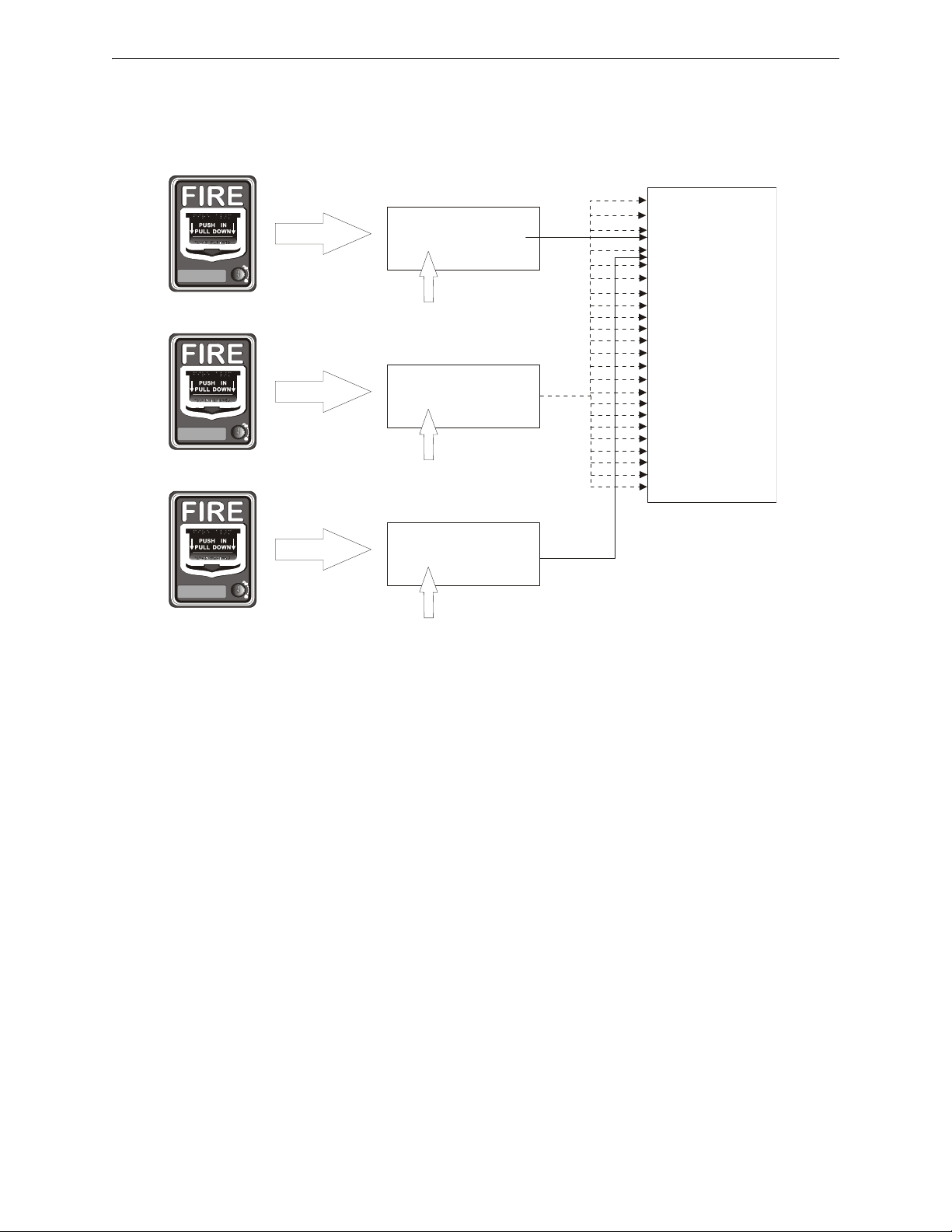
Programming Programmed Activation by FACP
Addressable Pull Station
(address 21)
Programmed to
Zone 32
Message 4
(lowest priority of the three)
Message 3
(2nd highest priority of the three)
Message 1
(highest priority of the three)
Addressable Pull Station
(address 09)
Zone 35
Programmed to
Zone 36
Programmed to
Addressable Pull Station
(address 15)
activate
activate
activate
Speaker Circuit 1
Speaker Circuit 2
Speaker Circuit 3
Speaker Circuit 4
Speaker Circuit 5
Speaker Circuit 6
Speaker Circuit 7
Speaker Circuit 8
Speaker Circuit 9
Speaker Circuit 10
Speaker Circuit 11
Speaker Circuit 12
Speaker Circuit 13
Speaker Circuit 14
Speaker Circuit 15
Speaker Circuit 16
Speaker Circuit 17
Speaker Circuit 18
Speaker Circuit 19
Speaker Circuit 20
Speaker Circuit 21
Speaker Circuit 22
Speaker Circuit 23
Speaker Circuit 24
e
c
c
e
x
2
.
w
m
f
example below) will be generated over speaker circuits 3 and 4. If an addressable device (address
21 in example below) programmed to Zone 32 is then activated, the highest priority message programmed to Zone 32, 35, or 36 (Message 1 in example below) will be generated over all speaker
circuits.
78 Emergency Command Center Manual — P/N LS10001-000FL-E:D 9/3/2014
FACP Message Assignment - Zone Specific
The F ACP can be programmed to allow a specific addressable input device to generate one of fourteen messages over any speaker circuit. Any one of the fourteen messages can be programmed to
each of the available zones (Zone 1 through Zone 99). In the following example, assume that Zone
5 is programmed to Message 1, Zone 7 is programmed to Message 2, and Zone 35 is not programmed to a message.
Example 3: If two devices are being programmed and the first addressable input device is pro-
grammed to Zone 7 and Zone 35, and a second addressable input device is programmed to Zone 5
and Zone 35, activation of the first addressable input device (address 12 in the example below) will
Page 79
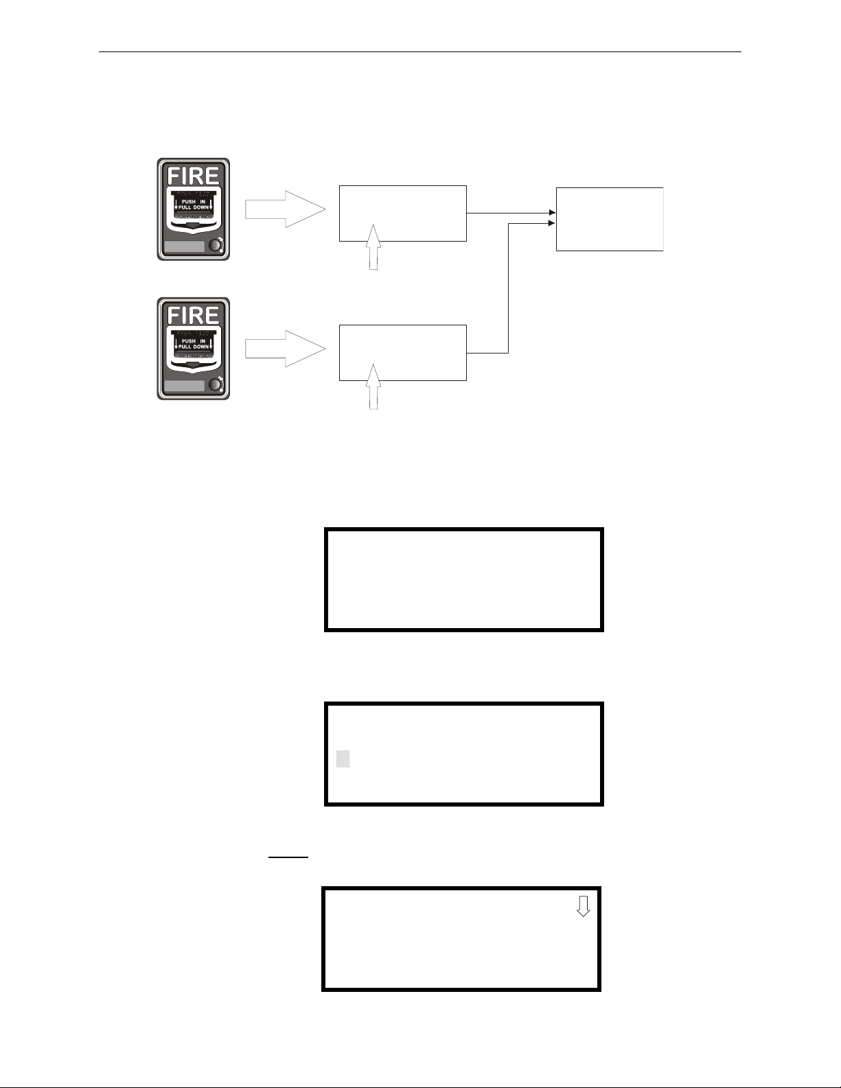
Programmed Activation by FACP Programming
Zone 5 and Zone 35
Zone 7 and Zone 35
Addressable Pull Station
(address 12)
Message 1
(highest priority of the three )
programmed to
activate
Speaker Circuit 3
Addressable Pull Station
(address 20)
programmed to
Message 2
(2nd highest priority of the three)
activate
e
c
c
e
x
3
.
w
m
f
1=READ STATUS MODE
2=PROGRAMMING MODE
3=MANUAL DIAL MODE
PROGRAMMING
ENTER PASSWORD
QQQQQ
PROGRAMMING
1=AUTOPROGRAM
2=POINT PROGRAM
3=ZONE SETUP
cause Message 2 to be generated over speaker circuit 3. If the second addressable device (address
20 in the example below) is also activated, Message 1 will now be transmitted over speaker circuit
3 since Message 1 has a higher priority then Message 2.
FACP Programming Menus
To Program one of fourteen messages to a speaker zone, press the ENTER key at the FACP. The
following screen will be displayed:
Access Programming Mode by pressing the 2 key. The following screen will be displayed:
Entering the Master
level password (default 00000) will cause the following screen to appear:
Emergency Command Center Manual — P/N LS10001-000FL-E:D 9/3/2014 79
Page 80

Programming Programmed Activation by FACP
ZONE SETUP
1=ENABLE
2=DISABLE
3=ZONE 97 98 99
Zone Setup Screen #1
ZONE SETUP
1=ZONES INSTALLED
2=ZONES ENABLED
3=ZONES DISABLED
Zone Setup Screen #2
ZONE SETUP
1=ZONE TYPES
2=ZONES AVAILABLE
3=ZONE MESSAGE
Zone Setup Screen #3
ZONE MESSAGE
1=Z00 NO MESSAGE
2=Z01 NO MESSAGE
3=Z02 NO MESSAGE
ZONE MESSAGE
1=Z30 NO MESSAGE
2=Z31 NO MESSAGE
3=Z32 NO MESSAGE
Select the Zone Setup option by pressing 3. The following screens will be displayed.
Pressing 3 while viewing Zone Setup Screen #3 will cause the following screen to be displayed:
Press the down arrow key until the following screen is displayed.
80 Emergency Command Center Manual — P/N LS10001-000FL-E:D 9/3/2014
Page 81

Programmed Activation by FACP Programming
ZONE MESSAGE
1=NO MESSAGE
2=MESSAGE 1
3=MESSAGE 2
ZONE MESSAGE
1=MESSAGE 3
2=MESSAGE 4
3=MESSAGE 5
ZONE MESSAGE
1=MESSAGE 6
2=MESSAGE 7
3=MESSAGE 8
ZONE MESSAGE
1=MESSAGE 9
2=MESSAGE 10
3=MESSAGE 11
ZONE MESSAGE
1=MESSAGE 12
2=MESSAGE 13
3=MESSAGE 14
The default setting is No Message for each speaker circuit. In the screen shown above, Z32 is the
zone dedicated for all speaker circuits. To change from No Message, press 3 to display the following screens:
Select the message (Message 1 through Message 14) by pressing the number corresponding to the
desired message. After the selection is made, the display will return to the screen displaying Z32
which will have changed from No Message to the selected message.
Repeat the procedure outlined above for each speaker zone (Z32 through Z56) and then exit Programming by pressing the Escape (ESC) key to save the programming changes. Test the system to
ensure proper operation.
Emergency Command Center Manual — P/N LS10001-000FL-E:D 9/3/2014 81
Page 82

Section 4: Operating Instructions
Figure 4.1 Keypad Labels
e
c
c
k
y
l
b
l
.
w
m
f
Remove
Install
Install
Remove
TROUBLE SILENCE
AC POWER
GROUND FAULT
CHARGER FAULT
BATTERY FAULT
DATA BUS FAULT
NAC FAULT
NAC ACTIVE
SYSTEM TROUBLE
AUDIO RISER FAULT
DIST. AMP 1
DIST. AMP 2
DIST. AMP 3
DIST. AMP 4
DIST. AMP 5
DIST. AMP 6
DIST. AMP 7
DIST. AMP 8
REMOTE AMPS
SPEAKER
ZONE 13
SPEAKER
ZONE 14
SPEAKER
ZONE 15
SPEAKER
ZONE 16
SPEAKER
ZONE 17
SPEAKER
ZONE 18
SPEAKER
ZONE 19
SPEAKER
ZONE 20
SPEAKER
ZONE 21
SPEAKER
ZONE 22
SPEAKER
ZONE 23
SPEAKER
ZONE 24
MNS
CONTROL
MESSAGE 1
MESSAGE 2
MESSAGE 3
MESSAGE 4
MESSAGE 5
MESSAGE 6
MESSAGE 7
OK TO PAGE
MICROPHONE
TROUBLE
4.1 Main Control Panel Keypad Labels
The ECC-50/100 is shipped with slide-in labels installed in the keypad as illustrated in the fo llowing figure. Blank labels are provided to allow the user to customize the zone and message description. Remove the center piece to access the label slots. Using a small, flat screwdriver, press and
release the small plastic latch located on the left side of the center piece.
be easily removed by sliding them down through the slots in the middle of the keypad and installed
by sliding them up. The bottom row of labels can be removed by sliding them up through the slots
in the middle of they keypad and installed by sliding them down into position.
The top row of labels can
4.2 ECC-50/100 Switch Functions
The ECC-50/100 display consists of 38 tactile push-button keys. Pressing one or more of the keys
while the panel is not
ually activated evacuation or drill signal. If the panel is in alarm, pressing a key corresponding to
an activated speaker circuit will turn off the circuit and turn on the Trouble LED.
All Call
Pressing this button activates all speaker circuits (that were not manually deactivated) for broadcast. ALL CALL paging from the main console's microphone will override paging/manual activation operations initiated from the other consoles (ECC-LOC, ECC-RPU, ECC-RM) or from a
F ACP (if programmed for priority to do so). If all consoles in the system are programmed for equal
priority then the ALL CALL will only occur when the system is not already in use (“System in
Use” LED is not on, remote console active LED is not on). Refer to the SYSTEM CONTROL but-
in alarm will select the corresponding circuit for paging or to generate a man-
82 Emergency Command Center Manual — P/N LS10001-000FL-E:D 9/3/2014
Page 83

LED Indicators Operating Instructions
ton description. When the operator completes the page, any previously interrupted emergency
broadcast will resume. Previously initiated emergency broadcast will also resume after the push-totalk (PTT) switch is held for more than 3 minutes (timer is programmable).
MNS Control
This button is only used when the system is configured for combination fire/mass notification operation or mass notification only operation.
For mass notification only operation, pressing this button will activate the “MNS active” relay and
the onboard NAC. A second press will de-activate the “MNS active” relay , turn main control board
NAC off, and cancel all broadcasting.
For combination systems (fire and mass notification) where mass notification has a higher priority
through user programming, pressing this button will result in the shutdown of audible F ACP NACs
and audio system speakers if they were active for fire. Pressing the button again causes the F ACP to
re-activate audible FACP NACs and audio system speakers if they were previously active for fire .
System Control
This button is used to manually gain control of the audio system in preparation for an ALL CALL,
message activation, or general page. The main console will have system priority based upon user
programming. If the main console has higher priority than other system consoles (ECC-LOC,
ECC-RPU, ECC-RM) then the green LED will turn on steady to confirm control. If no other console is in control then pressing this button is not necessary to gain system control. A second press
is required after paging to relinquish control of the system.
Speaker Select 1-24
These buttons are used to manually activate or deactivate speaker zones (circuits).
Message Select 1-14
These buttons are used to manually activate or deactivate stored messages. If the system has been
programmed for greater than 8 messages then button 8 (the bottom button) becomes a “shift” button. To activate messages 8 through 14, the user must press the “shift” button followed by a message button physically above it. Messages are in priority order where message 1 (the top button) has
highest priority. Pressing a higher priority message button after pressing a lower priority message
button will result in a message override.
For combination fire and MNS applications, messages must be organized per the system priority
setting. For example, if MNS has priority over fire, all MNS messages must be assigned/recorded
to higher priority message buttons than the fire messages. If fire has priority, then all fire messages
must be assigned/recorded to higher priority message buttons than the MNS messages.
Diagnostic Select
This button is used to examine specific trouble conditions for the remote amplifiers (distribut ed
audio amplifiers). The button is used to select or “scroll” to a specific remote amplifier. The fault
LEDs in the lower center of the display with “wrench” graphics will represent the amplifier
selected. When no amplifier is selected, those fault LEDs represent the main console status.
Trouble Silence
This button is used to manually silence the local trouble sounder.
Console Lamp Test
This button is used to test the console LEDs and local sounder. When pressed, all LEDs temporarily
light and the local sounder is turned on temporarily.
4.3 LED Indicators
Refer to Figure 1.4, “ECC-50/100 Keypad” on page 20.
Emergency Command Center Manual — P/N LS10001-000FL-E:D 9/3/2014 83
Page 84

Operating Instructions LED Indicators
Fire System Active
A green LED that turns on steady when the FACP is in alarm. This LED is used when the FACP to
ECC data bus has signaled a fire alarm or when any of the command inputs (CMD1-CMD8) has
activated for a fire alarm.
MNS Control
A green LED that turns on steady when an operator has initiated a mass notification event by pressing the MNS Control button or by pressing an MNS message button
System Control
A green LED that turns on steady when the main console has control of the audio system
System in Use
Green LED text that turns on steady when the main console, an LOC, an RPU, or an RM has control of the audio system
Speaker Zones 1-24
A green LED per speaker circuit button that turns on steady when a speaker circuit has been
selected and is active
A yellow LED per speaker circuit button that turns on steady when a speaker circuit fault exists or
when the speaker circuit has been turned off after having been automatically turned on by the F ACP
OK to Page
Green LED text that turns on steady to instruct the operator that he/she may start paging
Microphone Trouble
A yellow LED that turns on steady to indicate a microphone wiring fault
Messages
A red LED per message button that turns on steady when the message has been selected and blinks
when the message has been overridden
A yellow LED per message button that turns on steady when no message has been recorded or there
is an associated command input fault. All eight (8) message button LEDs will turn on steady to
indicate a message generator fault.
When more than eight (8) messages are enabled, the 8th message button becomes a “shift” key.
The red LED turns on when viewing messages 8-14 and off when viewing 1-7. The yellow LED
will turn on indicating an overridden message or message trouble in the group of messages not currently being viewed.
Remote Amplifiers 1-8 Fault
A yellow LED per remote amplifier (distributed audio) that turns on steady when an amplifier has a
fault. Specific, additional fault indication is annunciated via the fault LEDs with the “wrench”
graphic next to them on the keypad.
LOC/RPU/RM 1-8 Fault
A yellow LED per remote console that turns on steady when a remote console has a fault. Specific,
additional fault indication is annunciated by LEDs at the remote consoles.
A green LED per remote console that turns on steady when a remote console is active
Main Console Fault
A yellow LED that turns on steady when the main (or primary operator) console has a fault
AC Power
A green LED that turns on steady when AC power is present
84 Emergency Command Center Manual — P/N LS10001-000FL-E:D 9/3/2014
Page 85

Operation Operating Instructions
Ground Fault
A yellow LED that turns on steady when a ground fault exists in the system
Charger Fault
A yellow LED turns on steady when the battery charger voltage is too high or low
Battery Fault
A yellow LED that turns on steady when battery voltage is too low
Data Bus Fault
A yellow LED turns on steady when the main and remote console(s) cannot communicate
NAC Fault
A yellow LED that turns on steady when the onboard NAC wiring is open or short-circuited.
NAC Active
A green LED that turns on steady when the NAC output is on
System Trouble
A yellow LED that turns on steady when any fault exists in the system
Audio Riser Fault
A yellow LED that turns on steady when the audio riser wiring is open or short-circuited
4.4 Operation
The ECC-50/100 continuously monitors system status. When no system alarm or local trouble conditions exist, all LEDs are off except the AC Power On LED located on the front panel keypad.
The Notification Appliance Circuits are off and all relays are in their normal state.
4.4.1 Paging from the Microphone
1. The ECC-50/100 main console must be in control of the system to perform a page. If the green
System in Use LED is lit, press the SYSTEM CONTROL button. The ECC-50/100 is ready to
page once the System in Use LED turns off and the System Control LED lights steady. If the
System Control LED is already lit, this action is not required.
2. Activate desired paging areas. Press either the ALL CALL button, to page to all speaker
zones, or individual speaker zone buttons (1-24). This will override the evacuation
tone/message if the panel is in alarm and activate desired speaker circuits.
3. Key the microphone by pressing the push-to-talk switch on side of microphone. Speak clearly
into the microphone.
4. When finished speaking, release the push-to-talk switch.
5. Press the ALL CALL button (or individual speaker zone buttons pressed in step 2) to end the
broadcast and continue the evacuation tone/message.
6. Press the SYSTEM CONTROL button to relinquish control of the audio system.
4.4.2 Manual Message Control
1. The ECC-50/100 main console must be in control of the system to perform a page. If the green
System in Use LED is lit, press the SYSTEM CONTROL button. The ECC-50/100 is ready to
page once the System in Use LED turns off and the System Control LED lights steady. If the
System Control LED is already lit, this action is not required.
2. Activate desired message areas. Press either the ALL CALL button, to broadcast to all speaker
zones, or individual speaker zone buttons. This will override the evacuation tone/message if
the panel is in alarm and activate desired speaker circuits.
Emergency Command Center Manual — P/N LS10001-000FL-E:D 9/3/2014 85
Page 86

Operating Instructions Operation
3. Press the desired message button.
4. When the message has finished playing, press the ALL CALL button (or individual speaker
zone buttons pressed in step 2) to deactivate the message areas and continue the evacuation
tone/message.
5. Press the SYSTEM CONTROL button to relinquish control of the audio system.
4.4.3 Fire Alarm Response, System Configured for Fire Only
Upon detection of an alarm condition (any of CMD1 to CMD8 inputs active or automatic activation
from the FACP Data Bus) the system will:
• Turn the appropriate speaker zone LED(s) on steady
• Turn the appropriate speaker circuits on
• Turn the appropriate audio amplifier(s) on
• Turn the 24 VDC aux. power output on (if programmed)
• Turn the speaker volume control override on
• Turn the “System in Use” LED on steady
• Turn the “Fire System Active” LED on steady
• Play a leading tone (if programmed)
• Play and repeat the appropriate audio message (if programmed to repeat)
• Play an inter-message tone (if programmed)
• Play a primary evacuation tone only (if programmed)
• Store the event in the history log
4.4.4 Fire Alarm Restoral, System Configured for Fire Only
Upon restoral the system will:
• Turn the speaker zone LED(s) off
• Turn the speaker circuits off
• Turn the audio amplifier(s) off
• Turn the 24 VDC aux. power output off (if programmed)
• Turn the speaker volume control override off
• Turn the “System in Use” LED off
• Turn the “Fire System Active” LED off
4.4.5 Manual Activation
Upon pressing speaker zone button(s) followed by pressing a message button the system will:
• Turn the appropriate speaker zone LED(s) on steady
• Turn the appropriate speaker circuit(s) on
• Turn the appropriate message LED on steady
• Turn the appropriate audio amplifier(s) on
• Turn the 24 VDC aux. power output on (if programmed)
• Turn the speaker volume control override on
• Turn the “System in Use” LED on steady
• Activate the “MNS active” relay (if the system is programmed for mass notification)
• Activate the NAC output (if programmed to do so for mass notification)
• Play a leading tone (if programmed)
• Play and repeat the appropriate audio message (if programmed to repeat)
86 Emergency Command Center Manual — P/N LS10001-000FL-E:D 9/3/2014
Page 87

Operation Operating Instructions
• Play an inter-message tone (if programmed)
• Play a primary evacuation tone only (if programmed)
• Store the event in the history log
4.4.6 Manual Activation Restoral
Upon restoral the system will:
• Turn the speaker zone LED(s) off
• Turn the speaker circuit(s) off
• Turn the audio amplifier(s) off
• Turn the 24 VDC aux. power output off (if programmed)
• Turn the speaker volume control override off
• De-activate the “MNS active” output relay
• De-activate the NAC output (if programmed to do so for mass notification)
• Turn the “System in Use” LED off
4.4.7 Alarm/Alert Response, System Configured for Mass Notification Only
Upon detection of an alarm/alert condition (any of CMD1 to CMD8 inputs active) the system will:
• Turn all speaker zone LEDs on steady
• Turn all speaker circuits on
• Turn the appropriate audio amplifier(s) on
• Turn the 24 VDC aux. power output on (if programmed)
• Turn the speaker volume control override on
• Turn the “System in Use” LED on steady
• Activate the “MNS active” relay (if the system is programmed for mass notification)
• Activate the NAC output (if programmed to do so for mass notification)
• Play and repeat a leading tone (if programmed)
• Play and repeat the appropriate audio message (if programmed to repeat)
• Play an inter-message tone (if programmed)
• Play a primary alert tone only (if programmed)
• Store the event in the history log
4.4.8 Alarm/Alert Restoral, System Configured for Mass Notification Only
Upon restoral the system will:
• Turn the speaker zone LEDs off
• Turn the speaker circuits off
• Turn the audio amplifier(s) off
• Turn the 24 VDC aux. power output off (if programmed)
• Turn the speaker volume control override off
• De-activate the “MNS active” output relay
• De-activate the NAC output (if programmed to do so for mass notification)
• Turn the “System in Use” LED off
Emergency Command Center Manual — P/N LS10001-000FL-E:D 9/3/2014 87
Page 88

Operating Instructions Operation
4.4.9 Alarm/Alert Response, System Configured for Combo Fire/Mass Notification with Fire Priority
If a fire alarm only occurs under this configuration, then the system will respond as in Section 4.4.3
above.
If a mass notification alarm/alert only occurs under this configuration, then the system will respond
as in Section 4.4.7 above and additionally will:
• Signal the FACP of the alarm/alert using the FACP Data Bus such that the FACP can
annunciate the alarm/alert and notify a central station (if programmed to do so).
If a fire alarm is active in the system and a subsequent mass notification alarm/alert occurs, then the
system will not respond until the fire alarm has been restored.
4.4.10 Alarm/Alert Restoral, System Configured for Combo Fire/Mass Notification with Fire Priority
If the restoral is for a fire alarm only under this configuration then the system will respond as in
Section 4.4.4 above.
If the restoral is for a mass notification alarm/alert only under this configuration then the system
will respond as in Section 4.4.8 above and additionally will:
• Signal the FACP of the restoral using the FACP Data Bus such that the FACP can stop
annunciation of the alarm/alert and notify a central station (if programmed).
If the restoral is for a fire alarm that overrode an earlier active mass notification alarm/event then
the system will:
• Stop playing the fire alarm message
• Turn the “Fire System Active” LED off
• Return the system to the active state of the earlier mass notification alarm/event
4.4.11 Alarm/Alert Response, System Configured for Combo Fire/Mass Notification with Mass Notification Priority
If a fire alarm only occurs under this configuration then the system will respond as in Section 4.4.3
above.
If a mass notification alarm/alert only occurs under this configuration then the system will respond
as in Section 4.4.7 above. and additionally will:
• Signal the FACP of the alarm/alert using the FACP Data Bus such that the FACP can
annunciate the alarm/alert and notify a central station (if programmed to do so).
If a fire alarm is active in the system and a subsequent mass notification alarm/alert occurs, then the
system will:
• Stop playing the current fire message
• Signal the FACP of the alarm/alert using the FACP Data Bus such that the FACP can
annunciate the alarm/alert, notify a central station (if programmed), and turn off audible
NACs (if programmed).
• Respond as in Section 4.4.7 above
If a mass notification alarm/alert is active in the system and a subsequent fire alarm occurs, then the
system will not respond until the mass notification alarm/alert is restored.
88 Emergency Command Center Manual — P/N LS10001-000FL-E:D 9/3/2014
Page 89

Operation Operating Instructions
4.4.12 Alarm/Alert Restoral, System Configured for Combo Fire/Mass Notification with Mass Notification Priority
If the restoral is for a fire alarm only under this configuration then the system will respond as in
Section 4.4.4 above.
If the restoral is for a mass notification alarm/alert only under this configuration then the system
will respond as in Section 4.4.8 above.
If the restoral is for a fire alarm that was over ridden by a currently active mass notification
alarm/event then the system will:
• Continue playing the current mass notification message
• Turn the “Fire System Active” LED off
4.4.13 Tr ouble Condition Response
Upon detection of any trouble condition the system will:
• Activate (de-energize) the trouble relay
• Turn the local sounder on
• Turn the system trouble LED on
• Open command input 1 (CMD1) only if command input 1 is not in the alarm state
• Store the event in the history log
The following will occur on the display for more specific indication.
• For speaker circuit faults, the appropriate speaker zone fault LED(s) turns on steady
• For message faults, the appropriate message fault LED(s) turns on steady
• For a microphone fault, the microphone fault LED turns on steady
• For AC loss the AC power LED turns off, the AC loss and system trouble relays activate
(de-energize) (after a programmable time out).
• For a earth ground fault, the ground fault LED turns on steady
• For a battery charger fault, the battery charger fault LED turns on steady
• For a battery voltage fault, the battery fault LED turns on steady
• For a fault on the data bus to peripheral consoles, the data bus fault LED turns on steady
• For an onboard NAC fault, the NAC fault LED turns on steady
• For an audio riser fault, the audio riser fault LED turns on steady
• For a peripheral console fault, the associated peripheral console fault LED turns on steady
• For a distributed amplifier fault, the associated distributed fault LED turns on steady
For distributed amplifier faults, the following will occur on the display when the operator uses the
DIAGNOSTIC button to select a distributed amplifier for more specific indication.
• For a power fault, the AC power LED turns off
• For a ground fault, the ground fault LED turns on steady
• For a battery charger fault, the battery charger fault LED turns on steady
• For a battery voltage fault, the battery fault LED turns on steady
• For a fault on the data bus to peripheral consoles, the data bus fault LED turns on steady
The following will occur on the main control board for more specific indication.
• For speaker volume control fault, the speaker volume control fault LED(s) turns on steady
• For an amplifier over current fault, the amplifier over current fault LED turns on steady and
all associated speaker circuit fault LEDs turn on steady
Emergency Command Center Manual — P/N LS10001-000FL-E:D 9/3/2014 89
Page 90

Operating Instructions Operation
• For an option card missing (ECC-XRM-70V, ECC-50W-25/70V, ECC-CE6), the option
card LED turns on steady
The following actions will occur on the ECC-50W-25/70V optional amplifier for more specific
indication.
• For an over current condition, the over current LED turns on steady
4.4.14 Trouble Condition Restoral
Upon complete restoral the system will:
• De-Activate (energize) the trouble relay
• Turn the local sounder off
• Turn the system trouble LED off
• Close command input 1 (CMD1) only if command input 1 is not in the alarm state
• Store the event in the history log
The following will occur on the display for more specific indication when the specific fault
restores.
• For speaker circuits, the appropriate speaker zone fault LED(s) turns off
• For messages, the appropriate message fault LED(s) turns off
• For the microphone, the microphone fault LED turns off
• For AC power, the AC power LED turns on, the AC loss and system trouble relays deactivate (energize)
• For earth ground, the ground fault LED turns off
• For the battery, the battery charger fault LED turns off
• For battery voltage, the battery fault LED turns off
• For the data bus to peripheral consoles, the data bus fault LED turns off
• For the onboard NAC, the NAC fault LED turns off
• For the audio riser, the audio riser fault LED turns off
• For a peripheral console, the associated peripheral console fault LED turns off
• For a distributed amplifier, the associated distributed fault LED turns off
For distributed amplifier restorals, the following will occur on the display when the operator uses
the DIAGNOSTIC button to select a distributed amplifier for more specific indication.
• For power present, the AC power LED turns on
• For earth ground, the ground fault LED turns off
• For the battery charger, the battery charger fault LED turns off
• For battery voltage, the battery fault LED turns off
• For the data bus to peripheral consoles, the data bus fault LED turns off
The following will occur on the main control board for more specific indication when the specif ic
fault restores.
• For the speaker volume control, the speaker volume control fault LED(s) turns off
• For the amplifier over current, the amplifier over current fault LED turns off and all
associated speaker circuit fault LEDs turn off
• For the option cards (ECC-XRM-70V, ECC-50W-25/70V, ECC-CE6) the option card
missing LED turns off
The following actions will occur on the ECC-50W-25/70V optional amplifier for more specific
indication when the condition restores.
• For over current, the over current LED turns off
90 Emergency Command Center Manual — P/N LS10001-000FL-E:D 9/3/2014
Page 91

Operation Operating Instructions
4.4.15 External Audio Input Operation
The external audio input (aux. audio) located on the display board terminal TB5 can serve as any
one of the following:
• A background music input
• A message recording input from an audio source
• A general paging input from a paging microphone or telephone system
• A night ring input from a telephone system
The function of the external audio input must be selected in programming. Refer to “External
Audio Input” on page 71. For external audio input electrical requirements, “Input/Output Circuit
Specifications” on page 14.
When programmed, background music will play on all ECC-50/100 speaker circuits only when the
audio system is in a normal, standby condition. During alarm or alert operation of the audio system,
background music is suspended. Background music is also suspended during an AC power loss
condition to preserve the batteries. Speaker circuits on the main ECC-50/100 panel are fully supervised while background music is playing. Speaker circuits on the ECC-50DA or ECC-125DA distributed amplifiers are not supervised while playing background music.
For programming messages using the external audio input, refer to “Recording Custom Messages”
on page 70.
When programmed, the external audio input may be used for general paging or night ri ng operation. The building's “Private Branch Exchange (PBX)” telephone system or a third party microphone system must provide the audio signal along with a contact closure to trigger the paging or
night ring. Paging or night ring will occur only when the audio system is in a normal, standby condition. During alarm or alert operation of the audio system, paging or night ring is suspended. All
speaker circuits are fully supervised during paging or night ring operation. Refer to “Input/Output
Circuit Specifications” on page 14 for night ring electrical requirements. Refer to “Night Ring” on
page 35 for wiring requirements.
Emergency Command Center Manual — P/N LS10001-000FL-E:D 9/3/2014 91
Page 92

Section 5: Getting Started
This section describes the basic guidelines for setting up the various ECC-50/100 systems, assuming that the speaker and FACP cabling has been installed.
5.1 System Requiring up to 50 Watts of Audio Power
1. Install backbox and chassis assembly as described in Section 2, “Installation”, on page 26.
2. Connect laptop or PC to Ethernet port (J2) and launch the web-based programming utility.
3. Configure the ECC-50/100 for Single Zone operation, if individual speaker circuit control is
not required. The factory default setting is Single Zone output control. Refer to Section 3,
“Programming”, on page 59.
4. Record any new voice messages as described in Section 4, “Operating Instructions”, on page
82.
5.2 System Requiring Up to 100 Watts of Audio Power
1. Install backbox, chassis assembly, and ECC-50W-25/70V and circuit boards as describe d in
Section 2, “Installation”, on page 26.
2. Connect laptop or PC to Ethernet port (J2) and launch the web-based programming utility.
3. Configure the ECC-50/100 for Single Zone operation. Refer to Section 3, “Programming”, on
page 59.
4. Record any new voice messages as described in Section 4, “Operating Instructions”, on page
82.
5.3 System Requiring Greater Than 100 Watts of Audio Power
1. Install backbox and chassis assembly as described in Section 2, “Installation”, on page 26.
2. Connect the external Audio Riser and external Data Bus (for All-Call) cabling between the
ECC-50/100 and ECC-125DA and/or ECC-50DA panels.
3. Connect laptop or PC to Ethernet port (J2) and launch the web-based programming utility.
4. Configure the ECC-50/100 for Single Zone operation. Refer to Section 3, “Programming”, on
page 59.
5. Record any new voice messages as described in Section 4, ”Operating Instructions” on page
82.
6. Program the FACP to operate with the ECC-50/100 per the FACP manual.
– Enable the ACS-BUS serial link or ANN-BUS serial link.
– Assign audio zones where applicable (see Section 3.5, “Programmed Activation by FACP”,
on page 75).
– Assign message numbers (1 - 5) where applicable (refer to Section 3.5, “Programmed
Activation by FACP”, on page 75).
7. Connect the external Audio Riser and ECC external Data Bus cabling between the ECC50/100 and the ECC-125DA and/or ECC-50DA.
92 Emergency Command Center Manual — P/N LS10001-000FL-E:D 9/3/2014
Page 93

Section 6: Power Supply Calculations
6.1 Overview
This section contains instructions and tables for calculating power supply currents in alarm and
standby conditions. This is a four-step process, consisting of the following:
1. Calculating the total amount of AC branch circuit current required to operate the system
2. Calculating the power supply load current for non-fire and fire alarm conditions and
calculating the secondary (battery) load
3. Calculating the size of batteries required to support the system if an AC power loss occurs
4. Selecting the proper batteries for your system
6.2 Calculating the AC Branch Circuit
The audio distribution panel requires connection to a separate, dedicated AC branch circuit, which
must be labeled FIRE ALARM. This branch circuit must connect to the line side of the main
power feed of the protected premises. No other non-fire alarm equipment may be powered from
the fire alarm branch circuit. The branch circuit wire must run continuously, without any disconnect devices, from the power source to the transponder. Over-current protection for this circuit
must comply with Article 760 of the National Electrical Codes as well as local codes. Use 14 AWG
(2.00 mm
The ECC-50/100 requires 3.5 amps from the AC branch circuit. The ECC-50/100E requires 2.0
amps from the AC branch circuit.
2
) wire with 600 volt insulation for this branch circuit.
6.3 Calculating the System Current Draw
6.3.1 Overview
The secondary power source (batteries) must be able to power the system during a primary power
loss. To calculate the non-fire alarm load on the secondary power source, use Calculation
Column 1 in Table 6.3. The ECC-50/100 must support a larger load current during a fire alarm
condition and primary power loss. To calculate the fire alarm load on the secondary power source,
use Calculation Column 2 in Table 6.3.
When calculating current draw and the battery size, note the following:
• ‘Primary’ indicates that the audio panel is being powered by AC
• ‘Secondary’ indicates that the audio panel is being powered by battery backup during AC
failure
• All currents are given in amperes (A) and refer to the DC
Table 6.1 shows how to convert milliamperes and microamperes to full amperes
To convert.... Multiply Example
Milliamperes (mA) to
amperes (A)
Microamperes (µA) to
amperes (A)
Table 6.1 Converting to Full Amperes
mA x 0.001 3 mA x 0.001 = 0.003 A
µA x 0.000001 300 µA x 0.000001 = 0.0003 A
current being supplied by the panel.
Emergency Command Center Manual — P/N LS10001-000FL-E:D 9/3/2014 93
Page 94

Power Supply Calculations Calculating the System Current Draw
6.3.2 How to use Table 6.2 to calculate system current draws
1. Enter the quantity of devices in both columns.
2. Enter the DC current draw where required. Refer to the Fire•Lite Device Compatibility
Document for compatible devices and their current draw.
3. Calculate the current draws for each in both columns.
4. Sum the total current for each column.
5. Copy the totals from Column 1 and Column 2 to Table 6.3 on page 95.
Following are the types of current that can be entered into Table 6.2:
Calculation Column 1 - The standby current load that the audio panel must support (from
the batteries) during a non-fire alarm condition and a loss of AC power.
Calculation Column 2 - The alarm current draw that the audio panel must support (from
the batteries) during a fire alarm condition and a loss of AC power
Table 6.2 contains two columns for calculating current draws. For each column, calculate the current and enter the total (in amps) in the bottom row. When finished, copy the totals from Calculation Column 1 and Calculation Column 2 to Table 6.3 on page 95.
Calculation Column 1
Secondary (Battery) Power Source
Device Type
ECC-50/100 Primary Console
(Not including speaker load)
ECC-50W-25/70V
Optional Audio Amplifier Module
ECC-CE6 Speaker Circuit Expander [ ]
ECC-LOC Local Operator Console
ECC-RM Remote Microphone
ECC-RPU Remote Page Unit
ECC-50DA, ECC-125DA, ECC-50BDA
Remote Amplifiers
ECC-FFT Firefighter Telephone [ ] X[0.120]= [ ] [ ] X[0.230]= [ ]
Speakers (50 watts maximum/amplifier)
1/4 Watt
1/2 Watt
3/4 Watt
1 Watt
2 Watts
Additional Current Draw from TB17 Special
Application Auxiliary Power Output
(0.5 amp maximum)
NAC Circuit Output (2.0 amps maximum)
Power Supervision Relays
AIM-1A, RSM-1A Isolators [ ] X [0.0145]= [ ] [ ] X [0.0145]= [ ]
SP-SVC Volume Control [ ] X[0.010]= [ ] [ ] X[0.010]= [ ]
Sum each column for totals Secondary Standby: Secondary Alarm:
3
1
2
2
2
4
Standby Current (amps)
Qty
1 X [0.272]= 0.272 1 X [0.446]= 0.446
[ ]
(1 max.)
(1 max.)
[ ] X [0.085]= [ ] [ ] X [0.100]= [ ]
[ ] X [0.050]= [ ] [ ] X [0.064]= [ ]
[ ] X [0.050]= [ ] [ ] X [0.068]= [ ]
[ ] X [0.012]= [ ] [ ] X [0.012]= [ ]
[ ] X [ ]= [ ] [ ] X [ ]= [ ]
[ ] X [0.025]= [ ] [ ] X [0.025]= [ ]
X [current
draw] =
X [0.100]= [ ]
X [0.020]= [ ]
total Qty
Calculation Column 2
Secondary (Battery) Power Source
Alarm Current (amps)
X [current draw]
=
[ ]
(1 max.)
[ ]
(1 max.)
[ ] X[0.017]= [ ]
[ ] X[0.033]= [ ]
[ ] X[0.050]= [ ]
[ ] X[0.068]= [ ]
[ ] X[0.132]= [ ]
[ ] X [ ]= [ ]
X [0.235]= [ ]
X [0.189]= [ ]
total
Table 6.2 System Current Draw Calculations
1 In backup configurations, the optional amplifier draws no additional current in alarm.
2 Maximum combined total of eight (8) operator interface devices.
3 Maximum combined total of eight (8) remote amplifiers.
4 Must use a compatible, UL-listed Power Supervision Relay
94 Emergency Command Center Manual — P/N LS10001-000FL-E:D 9/3/2014
Page 95

Calculating the Battery Size Power Supply Calculations
6.4 Calculating the Battery Size
Use Table 6.3 to calculate the total Standby and Alarm load in ampere hours (AH). This total load
determines the battery size (in AH), required to support the ECC-50/100 under the loss of AC
power. Complete Table 6.3 as follows:
1. Enter the totals from Table 6.2 on page 94 Calculation Columns 1 and 2 where shown.
2. Enter the NFPA Standby and Alarm tim es (refer to Section 6.4 .1 , “NFPA Battery
Requirements”).
3. Calculate the ampere hours for Standby and Alarm, then sum the Standby and Alarm ampere
hours.
4. Multiply the sum by the derating factor of 1.2 to get the proper battery size (in AH).
5. Write the ampere hour requirements on the Protected Premises label located inside the cabinet
door.
Secondary Standby Load
(total from Table 6.2 Calculation Column 1)
[ ]
Secondary Alarm Load
(total from Table 6.2 Calculation Column 2)
[ ]
Sum of Standby and Alarm Ampere Hours = AH
Multiply by the Derating Factor X 1.2
Battery Size, Total Ampere Hours Required = AH
Required Standby Time
(24 or 60 hours)
[ ] = AH
Required Alarm Time
(for 5 min., enter 0.084,
for 10 min., enter 0.168,
for 15 min., enter 0.250)
for 30 min., enter 0.50)
[ ] = AH
Table 6.3 Total Secondary Power Requirements at 24 VDC
6.4.1 NFPA Battery Requirements
NFPA requires 24 hours of standby plus 15 minutes activation for audio systems. The total ampere
hours required cannot exceed 26 AH with an internal charger. An external charger can be used to
increase the total ampere hours (internal charger must be disabled).
6.4.2 Selecting and Locating Batteries
Select batteries that meet or exceed the total ampere hours calculated in T able 6.3. The audio panel
can charge batteries in the 12 AH to 26 AH range. The ECC-50/100 can house up to 18 AH batteries.
Emergency Command Center Manual — P/N LS10001-000FL-E:D 9/3/2014 95
Page 96

Appendix A: Digital Voice Messages
The Emergency Command Center digital message generator provides up to 14 messages each with
up to 60 seconds of record time. The ECC-50/100 is provided with factory recorded messages
which can be changed in the field. The prerecorded messages (female voice) are:
Fire Evacuation Messages:
• “May I have your attention, please? May I have your attention, please? A fire has been
reported in the building. A fire has been reported in the building. Please proceed to the
stairways and exit the building. Do not use the elevators.”
• Su atención por favor. Su atención por favor. Un incendio se ha reportado en el edificio. Un
incendio se ha reportado en el edificio. Por favor, proceder a las escaleras y salir del edificio.
No use los ascensores.
• “May I have your attention, please? May I have your attention, please? There has been a fire
reported in the building. Please proceed to the nearest exit and leave the building.”
• Su atención por favor. Su atención por favor. Un incendio se ha reportado en el edificio. Un
incendio se ha reportado en el edificio. Por favor, proceder a la salida mas cercana y salir del
edificio.
• “May I have your attention, please? May I have your attention, please? An alarm has been
activated in the building. Please proceed to the stairways and exit the building. Do not use the
elevators.”
• “May I have your attention, please? May I have your attention, please? There has been a fire
reported on your floor. There has been a fire reported on your floor. Please proceed to the
stairways and exit the building. Do not use the elevators.”
• “May I have your attention, please? May I have your attention, please? A fire has been
reported in the building. A fire has been reported in the building. Please proceed to the nearest
exit and leave the building. Do not use the elevator, but proceed to the nearest exit and leave
the building.”
Fire Alert Message:
• “May I have your attention please? An alarm has been activated. We are investigating the
cause. Please remain calm and stand by near the speakers for further instructions.”
Emergency Evacuation Messages:
• “May I have your attention, please? May I have your attention, please? There has been an
emergency reported in this area. Please proceed to the closest exit or stairwell and leave the
building. Do not use the elevators.”
• Su atención por favor. Su atención por favor. Una emergencia se ha reportado en este área. Por
favor, proceder a la salida mas cercana o escaleras y salir del edificio. No use los ascensores.
Emergency Alert Message:
• “Attention, please. This signal tone you have just heard indicates a report of an emergency in
this building. If your floor evacuation signal sounds after this message, walk to nearest
stairway and leave the floor. While the report is being verified, occupants on other floors
should await further instructions.”
All Clear Emergency Messages:
• “Attention. Your attention, please. The building emergency condition has been cleared. You
may return to your normal activities. The building emergency has been cleared. You may
return to your normal activities.”
• Atención. Su atención por favor. La condición de emergencia del edificio se ha resuelto.
Regrese a sus actividades normales. La emergencia del edificio se ha resuelto. Regresa a su
actividades normales.
96 Emergency Command Center Manual — P/N LS10001-000FL-E:D 9/3/2014
Page 97

Digital Voice Messages
Severe Weather Message:
• “Your attention please. A severe weather warning has been received. Please walk to the nearest
safe area and wait for further instructions. Elevator lobbies, stairwells, bathrooms and
auditoriums are designated safe areas in the event of severe weather . S tay away from windows
and glass. Do not use the elevators”
New messages can be recorded in the field. Be certain to get the approval of the local Authority
Having Jurisdiction prior to recording new messages.
Emergency Command Center Manual — P/N LS10001-000FL-E:D 9/3/2014 97
Page 98

Appendix B: Wiring Requirements
Connecting external system accessories to the ECC-50/100 main circuits must be carefully considered to ensure proper operation. It is important to use the correct type of wire, wire gauge and wire
run length per each circuit. Refer to the following table to specify wire requirements and limitations.
NOTE: If an SLC loop is to be run in conduit with ECC-50/100 Notification Appliance Circuits, the
risk of encountering problems can be greatly reduced by using twisted, shielded cable on the SLC
and NACs.
Wire Gauge
Circuit Type Wire Type & Limitations Maximum Distance (feet)
CMD1-CMD2
TB4, TB5: polarity reversal
CMD1-CMD2
TB4, TB5: contact closure
CMD3-CMD8
TB6-TB8: contact closure
speaker circuits
TB20, TB21
ECC-CE6 speaker circuits
TB1 - TB6
external data bus: TB12 twisted/shielded max loop impedance 13.2 ohms 12-18 AWG
external audio riser: TB22 twisted/shielded max loop impedance 13.2 ohms 12-18 AWG
external operator interface power:
TB24
NAC output: TB19 untwisted/unshielded,
speaker volume control override:
TB23
night ring input: TB16 untwisted/unshielded,
external audio input
TB5 (on display board)
MNS active, AC loss, and trouble
output relays: TB1 - TB3
auxiliary power: TB17 untwisted/unshielded, see note
untwisted/unshielded,
twisted/shielded, see note
untwisted/unshielded,
twisted/shielded, see note
untwisted/unshielded,
twisted/shielded, see note
untwisted/unshielded,
twisted/shielded, see note
untwisted/unshielded,
twisted/shielded, see note
untwisted/unshielded,
twisted/unshielded
twisted/unshielded
untwisted/unshielded,
twisted/unshielded
twisted/unshielded
twisted/shielded max loop impedance 100 ohms 12-18 AWG
untwisted/unshielded,
twisted/shielded, see note
1
1
1
2
2
1
depends on trigger circuit,
9-32 VDC, 1.6 mA
max loop impedance 200 ohms 12-18 AWG
max loop impedance 200 ohms 12-18 AWG
determine using Lite-Calcs utility
see note
determine using Lite-Calcs utility
see note
max loop impedance 13.2 ohms 12-18 AWG
refer to Section 2.6.3 , max loop
impedance 120 ohms
max loop impedance 120 ohms 12-18 AWG
max impedance 30 K ohms 12-18 AWG
depends on the panel monitoring
these outputs
1
distance set by 4 VDC max line
drop
3
3
(terminals support)
12-18 AWG
12-18 AWG
12-18 AWG
12-18 AWG
12-18 AWG
12-18 AWG
Table B.1 Wiring Requirements
1 Refer to NEC Standards.
2 Twisted, shielded wire is recommended for maximum protection against EMI and AFI emissions and
susceptibility.
3 Must also meet NFPA 72 Standards for minimum and maximum sound levels.
NOTE: Wire to wire short circuit trouble = zero ohms.
Open circuit trouble = infinite ohms.
Ground fault trouble = zero ohms to ground.
98 Emergency Command Center Manual — P/N LS10001-000FL-E:D 9/3/2014
Page 99

Appendix C: Canadian Applications
When using the ECC in Canadian Applications, note the following:
• The ECC-50/100 is for fire evacuation use only.
• The ECC-50DA, ECC-125DA, and ECC-50BDA amplifiers are not permitted for use in
Canada.
• The ECC-RPU and ECC-RM are not permitted for use in Canada.
• The ECC-50/100 must be mounted next to the FACP.
C.1 Audio Room Isolator Modules
C.1.1 Description
The audio isolator modules described below may be used to isolate short circuits during alarm signaling.
AIM-1A This module provides isolation to a separate circuit on an audio riser. A short circuit on
an AIM-1A speaker circuit will not disable other speaker circuits on the riser.
RSM-1A This module works the same as the AIM-1A, with the exception that there is a silence
button for in-suite operation. The silence button will silence the audible signal to the module’s circuit for ten minutes during alarm. Resounding will occur automatically after ten minutes or upon
activation of a new audio alert.
C.1.2 Panel Programming
“Canadian Configuration” and “Canadian Isolator Modules” must be enabled in ECCNFC programming. Refer to “General/NAC Options” on page 61. In addition, “NAC Type” must be set for
steady operation. See “NAC Options” on page 62.
Emergency Command Center Manual — P/N LS10001-000FL-E:D 9/3/2014 99
Page 100

Canadian Applications Audio Room Isolator Modules
AIM-1A
Remove jumpers 1 & 2.
RSM-1A
Remove jumpers 1 & 2.
Jumper 3
AIM-1A
RSM-1A
v
o
i
c
e
-
A
I
M
-
1
b
a
c
k
.
w
m
f
v
o
i
c
e
-
R
S
M
-
1
b
a
c
k
.
w
m
f
Figure C.1 Jumper Settings
From
ECC
Speaker
Circuit
From
ECC
Speaker
Circuit
TB19 on
ECC
NAC
(24VDC)
TB19 on
ECC
NAC
(24VDC)
AIM-1A/
RSM-1A
AIM-1A/
RSM-1A
to next module, ELR,
or Class A return
to next module, ELR, or Class A return
24V to next
device
24V to
next
device
optional
4-wire
return
Figure C.2 RSM-1A/AIM-1A Module Wiring
e
c
c
r
i
s
e
r
m
o
d
_
r
s
m
a
i
m
.
w
m
f
e
c
c
r
i
s
e
r
m
o
d
_
r
s
m
a
i
m
u
n
s
u
p
v
.
w
m
f
Supervised Speakers Non-supervised Speakers
C.1.3 Applications
The following figures illustrate typical applications for audio isolator modules. Jumper settings are
specified below to configure operation with speaker circuits. Jumpers are located on the back side
of each module.
100 Emergency Command Center Manual — P/N LS10001-000FL-E:D 9/3/2014
 Loading...