

Page 1

FIATFIORINOQUBO
OWNER HANDBOOK
Page 2
Dear customer,
Thank you for choosing Fiat and congratulations on your choice of a Fiat QUBO.
We have written this handbook to help you get to know all your new Fiat QUBO's features and use it in the best
possible way. You should read it carefully before taking to the road for the first time. You will find information, tips and
important warnings regarding driving your vehicle to help you get the most from the technological features of your FIAT
QUBO.
Read the warnings and indications, marked with the following symbols:
personal safety;
car safety;
environmental protection.
The enclosed Warranty Booklet lists the services that Fiat offers to its Customers:
❒ the Warranty Certificate with terms and conditions for maintaining its validity;
❒ the range of additional services available to Fiat Customers.
Enjoy reading. Happy motoring!
This Owner Handbook describes all Fiat QUBO versions. As a consequence, you
should only consider the information which is related to the trim level, engine and
version that you have purchased.
Page 3
READ THIS CAREFULLY!
REFUELLING
Diesel engines: only use diesel fuel for motor
vehicles conforming to the European specification
EN 590. The use of other products or mixtures
may damage the engine beyond repair and
consequently invalidate the warranty, depending
on the damage caused.
STARTING THE ENGINE
Diesel engines: Turn the ignition key to MAR
and wait for the warning light to go out.
Turn the ignition key to AVV and release as soon
as the engine starts.
PARKING ON FLAMMABLE MATERIAL
The catalytic converter develops high
temperatures during operation. Do not park the
vehicle on grass, dry leaves, pine needles or
other flammable material as this constitutes a fire
hazard.
RESPECTING THE ENVIRONMENT
The vehicle is fitted with a system that allows
continuous diagnosis of the emission-related
components in order to help protect the
environment.
ELECTRICAL ACCESSORIES
If, after buying the vehicle, you decide to add
electrical accessories (with the risk of gradually
draining the battery), visit a Fiat Dealership. They
can calculate the overall electrical requirement
and check that the electrical system of the
vehicle can support the required load.
SCHEDULED SERVICING
Correct maintenance is essential for ensuring the
vehicle stays in tip-top condition and retains its
safety features, its environmental friendliness and
low running costs for a long time to come.
THE OWNER'S HANDBOOK CONTAINS…
... important information, advise and warnings for
correct use, driving safety and maintenance of
your vehicle over time. Particular attention
should be paid to information marked with the
following symbols: (personal safety),
(environmental protection), (car integrity).
Page 4
KNOW YOUR VEHICLE
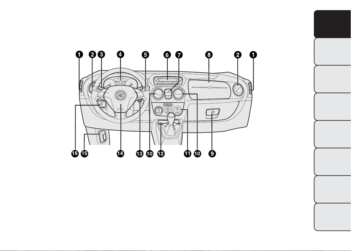
DASHBOARD
The presence and position of controls, instruments and indicators may vary according to the versions.
KNOW YOUR
VEHICLE
SAFETY
ST
ARTING AND
DRIVING
WARNING LIGHTS
AND MESSAGES
IN AN EMERGENCY
fig. 1
1. Vent for directing air to the side windows 2. Adjustable air vent 3. Left-hand stalk: exterior lights 4. Instrument panel
and warning lights 5. Right-hand stalk: front and rear windscreen wipers, trip computer 6. Radio (for versions/markets,
where applicable) 7. Emergency light switch, heated rear window switch, ASR/Traction Plus on/off switch (for
versions/markets, where provided), rear swing door lock button (for versions/markets, where provided) 8. Passenger's air
bag (for versions/markets, where provided) 9. Glove box/oddment tray (for versions/markets, where provided)
10. Adjustable air vents 11. Heating/ventilation/climate control system controls 12. Glove compartment 13. Ignition
switch 14. Driver's air bag 15. Bonnet opening lever 16. Controls display: fog light/rear fog light/head light alignment
adjustment/display
F0T0070
SERVICING AND
MAINTENANCE
TECHNICAL
SPECIFICATIONS
INDEX
3
Page 5
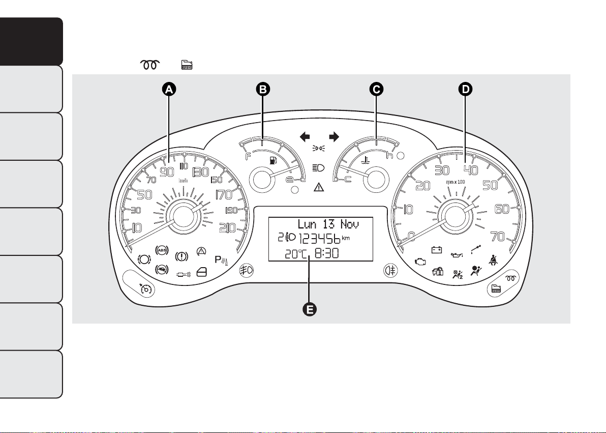
INSTRUMENT PANEL
KNOW YOUR
VEHICLE
ST
ARTING AND
DRIVING
WARNING LIGHTS
AND MESSAGES
IN AN EMERGENCY
SERVICING AND
MAINTENANCE
Versions with multifunction display
Warning lights
SAFETY
and are available on diesel versions only.
TECHNICAL
SPECIFICATIONS
INDEX
4
fig. 2
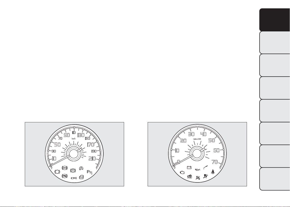
A. Speedometer (speed indicator) B. Fuel level gauge with reserve warning light C. Engine coolant temperature gauge
with overheating warning light D. Rev counter E. Multifunction display
F0T0460
Page 6
SYMBOLS
Special coloured labels have been attached near or
on some of the components of your vehicle. These
labels bear symbols that draw your attention to
the precautions required when handling the
component in question.
The inner surface of the engine bonnet includes a
label with the different symbols used.
THE FIAT CODE SYSTEM
This is an electrical engine immobiliser system which
increases protection against attempted theft of the
vehicle. It is automatically activated when the ignition
key is extracted.
Each time the vehicle is started turning the ignition
key to MAR, the Fiat CODE system control unit
sends a recognition code to the engine control unit
to deactivate the inhibitor.
If, during ignition, the code is not correctly
recognized, a warning light
instrument panel.
In this case, turn the key to STOP and then back to
MAR. Try with the other keys provided if the
problem persists. Contact a Fiat Dealership if you
still cannot start the engine.
is lit on the
KNOW YOUR
VEHICLE
SAFETY
ST
ARTING AND
DRIVING
WARNING LIGHTS
AND MESSAGES
IMPORTANT Each key has its own code which must
be stored by the system ECU. Contact the Fiat
Dealership to have new keys (up to eight) stored
with the code.
Warning light
❒ If the
comes on, this means that the system is running a
self-diagnosis test (caused, for example, by a
voltage drop). When you stop for the first time,
turn the key to STOP and then to MAR: the
warning light
detected.
warning light (or symbol in the display)
coming on when driving
will not light up if no faults are
IN AN EMERGENCY
SERVICING AND
MAINTENANCE
TECHNICAL
SPECIFICATIONS
INDEX
5
Page 7

❒ If the warning light (or symbol on the display)
KNOW YOUR
VEHICLE
❒ The code is not recognised if the warning light
SAFETY
ST
ARTING AND
DRIVING
WARNING LIGHTS
AND MESSAGES
stays on, repeat the procedure described above
leaving the key at STOP for longer than 30
seconds. If the problem persists, contact the Fiat
Dealership.
(or symbol on the display) stays on. In this
case, turn the key to STOP and then to MAR; if it
is still locked, try again with the other keys that
come with the vehicle. If you still cannot start the
engine, perform the emergency start procedure
(see chapter “In an emergency”) and then contact
the Fiat Dealership.
The electronic components inside the key
may be damaged if the key is subjected
to sharp knocks.
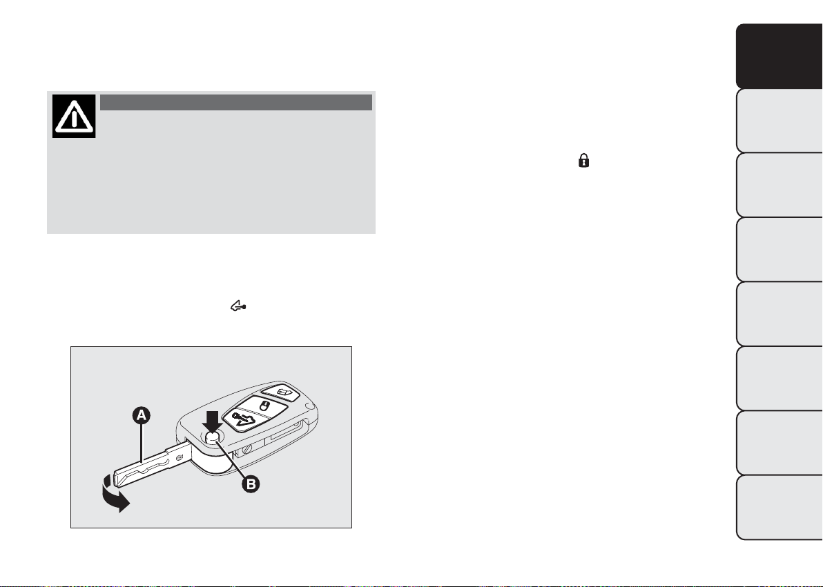
KEYS
KEY WITHOUT REMOTE CONTROL
The metal insert A fig. 3 operates:
❒ the ignition switch;
❒ the door locks;
❒ opening/closing the fuel cap.
KEY WITH REMOTE CONTROL
(for versions/markets, where provided)
The metal insert A fig. 4 operates:
❒ the ignition switch;
❒ the door locks;
❒ opening/closing the fuel cap.
IN AN EMERGENCY
SERVICING AND
MAINTENANCE
TECHNICAL
SPECIFICATIONS
INDEX
6
To extract the metal insert, press button B fig. 4.
To retract it in the grip, proceed as follows:
fig. 3
F0T0002
Page 8
❒ hold down button B and move the metal insert A;
❒ release button B and turn the metal insert A
until you hear the click.
WARNING
Only press button B with the key away
from
your body, specifically from your
eyes and from objects which could get damaged
(e.g. your clothes). Do not leave the key
unattended to avoid the button being
accidentally pressed while it is being handled,
e.g. by a child.
Opening the windows with the remote control
(for versions/markets, where provided)
Hold the button (on the key)
pressed for more
than 3 seconds to open the windows. Keep the
button pressed to open the windows completely; if
the pressure is suspended, the windows will
immediately stop in their current position. The same
type of opening is also possible by operating the
pawl of the front door handles.
Closing the windows with the remote control
(for versions/markets, where provided)
Hold the button (on the key)
pressed for more
than 3 seconds to close the windows. To close the
windows completely, keep the button pressed; if the
pressure is suspended, the windows will immediately
stop in their current position. The same type of
closing is also possible by operating the pawl of the
front door handles.
IMPORTANT During this operation the window
ant-crush safety system is inhibited.
KNOW YOUR
VEHICLE
SAFETY
ST
ARTING AND
DRIVING
WARNING LIGHTS
AND MESSAGES
IN AN EMERGENCY
SERVICING AND
MAINTENANCE
fig. 4
TECHNICAL
SPECIFICATIONS
INDEX
F0T0241
7
Page 9
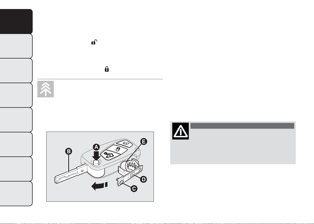
Changing battery - key with remote control
KNOW YOUR
VEHICLE
To replace the battery, proceed as follows fig. 5:
❒ press button A and bring the metal insert B to the
open position;
❒ turn the screw C to
SAFETY
❒ take out the battery case D and replace the
battery E, respecting its polarity;
❒ refit the battery case D inside the key and fasten it
ST
ARTING AND
by turning the screw C to
DRIVING
WARNING LIGHTS
AND MESSAGES
specified by law or by taking them to a Fiat
Dealership, which will deal with their disposal.
IN AN EMERGENCY
SERVICING AND
MAINTENANCE
TECHNICAL
SPECIFICATIONS
using a fine bit screwdriver;
.
Used batteries are harmful to the
environment.You can dispose of them
either in the correct containers as
ORDERING ADDITIONAL REMOTE
CONTROLS
The system acknowledges up to 8 remote controls.
Should a new remote control be necessary, contact a
Fiat Dealership, taking a personal identity document
and the vehicle ownership documents with you.
DEAD LOCK
(for versions/markets, where provided)
This security device prevents the opening of the
doors from inside the passenger compartment
if there has been a break-in attempt (e.g. a window
has been broken).
Dead lock therefore offers the best possible
protection against break-in attempts. We
recommend engaging it whenever the vehicle is
parked and left unattended.
WARNING
Once the dead lock system is engaged it
is
impossible to open the doors from
inside the vehicle. Before engaging the system
please therefore check that there is no one left
on board.
INDEX
8
fig. 5
F0T0300
Page 10
WARNING
If the remote control battery is flat, the
sys
tem can be engaged by inserting
the metal key in the door lock as described
previously: in this case, the device only remains
active for the rear doors.
Switching the device on
The system is automatically enabled on all the doors
by pressing button
control.
The direction indicators flash twice to let you know
that the device is active.
If one or more of the doors is not perfectly shut, the
dead lock device will not be activated, thus
preventing a person getting into the car through the
open door and, on shutting, it, remaining stuck
inside the passenger compartment.
Switching the device off
The system is disabled automatically on every door
when:
❒ by unlocking the doors;
❒ by turning the ignition key to the ON position.
twice on the key with remote
ALARM
(for versions/markets, where provided)
The alarm, in addition to all the previously described
remote control functions, is controlled by the
receiver located under the dashboard near the fuse
box.
ALARM TRIPPING
The alarm trips in the following cases:
❒ unauthorised opening of a door, the bonnet, the
tailgate or a sliding side door (if present)
(perimeter protection)
❒ unauthorized operation of the starting device (key
turned on using a key that is not enabled)
❒ cutting of the battery leads
❒ moving presence inside the passenger
compartment (volumetric protection)
❒ anomalous lifting/tilting of the vehicle.
Depending on the market, the activation of the alarm
causes the activation of the siren and the direction
indicators (for about 26 seconds). Alarm tripping and
the number of cycles depend on the sales market.
There are a maximum number of acoustic/visual
cycles. When this is reached the system returns to
normal operation.
Volumetric and antilifting protections are disabled by
pressing the control button installed on the front
dashboard (see paragraph "Antilift protections).
KNOW YOUR
VEHICLE
SAFETY
ST
ARTING AND
DRIVING
WARNING LIGHTS
AND MESSAGES
IN AN EMERGENCY
SERVICING AND
MAINTENANCE
TECHNICAL
SPECIFICATIONS
INDEX
9
Page 11

IMPORTANT The engine immobilizer function is
KNOW YOUR
VEHICLE
ST
ARTING AND
DRIVING
WARNING LIGHTS
AND MESSAGES
IN AN EMERGENCY
SERVICING AND
MAINTENANCE
TECHNICAL
SPECIFICATIONS
ensured by the Fiat CODE which is automatically
activated when the key is extracted from the ignition.
TURNING THE ALARM ON
With the doors and bonnet closed and the ignition
SAFETY
key either turned to STOP or removed, point the
key with the remote control towards the vehicle and
press and release button
Except for some markets, the system produces an
acoustic warning (beep) and enables door locking.
A self-diagnostic stage precedes the turning on of the
alarm: if a fault is detected, the system produces
another acoustic signal.
In this case switch off the alarm by pressing
check that all the doors, bonnet and tailgate are
closed correctly; then switch the alarm back on by
pressing
If a door or the bonnet is not properly shut, it will
be excluded from the testing by the alarm system.
A fault has occurred in system operation if the alarm
produces an acoustic signal even when the doors,
bonnet and boot are correctly closed. Go to a
Fiat Dealership.
IMPORTANT The alarm does not come on when the
central locking is activated using the metal insert in
the key.
TURNING THE ALARM OFF
Press button
The following operations are performed (excluding
specific markets):
❒ direction indicators flash briefly twice
❒ two short beeps
.
,
.
❒ door are unlocked.
IMPORTANT The alarm is not turned off using the
door are opened using the metal insert in the key.
VOLUMETRIC/ANTILIFTING PROTECTION
The side windows must be completely closed for
correct operation of the protection.
If necessary, the function can be turned off (if, for
example, you are leaving a pet in the car) by pressing
button A fig. 6 on the front courtesy light before
activating turning the alarm on.
The LED on the button will flash for several seconds
when the function is turned off. The volumetric/
antitilting protection must be deactivated each time
the instrument panel is switched off.
on the key with the remote control.
10
IMPORTANT The alarm is configured to comply with
INDEX
the regulations existing in different countries.
Page 12
BREAK-IN ATTEMPT INDICATION
The warning light
comes on or the symbol
appears on the display with a specific message (see
"Warning lights and messages" when the panel lights
up according to vehicle version) to indicate a
break-in attempt.
DISABLING THE ALARM
To permanently disable the alarm (e.g. during a long
storage), simply lock the vehicle by turning the
metal insert of the key with remote control in the
lock. In this case, the car will not be protected
by the alarm system, while the engine immobiliser
function is ensured by the Fiat CODE system, which
is automatically activated when the key is removed
from the ignition switch.
IMPORTANT If the batteries in the remote control
key are run down or if the system is faulty, the
key must be inserted in the ignition and turned to
the ON position to switch the alarm off.
KNOW YOUR
VEHICLE
SAFETY
ST
ARTING AND
DRIVING
WARNING LIGHTS
AND MESSAGES
IN AN EMERGENCY
SERVICING AND
MAINTENANCE
fig. 6
TECHNICAL
SPECIFICATIONS
INDEX
F0T0159
11
Page 13
IGNITION SWITCH
KNOW YOUR
VEHICLE
ST
ARTING AND
DRIVING
WARNING LIGHTS
AND MESSAGES
IN AN EMERGENCY
SERVICING AND
MAINTENANCE
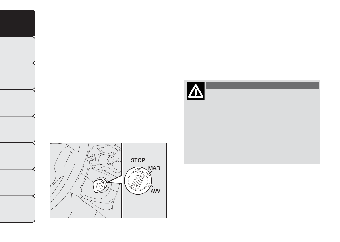
The key can be turned to 3 different positions fig. 7:
❒ STOP: engine off, key extractable, steering locked.
Some electrical devices (e.g. car radio, central
SAFETY
door locking system, alarm, etc.) can work.
❒ MAR: driving position. All electrical devices can
work.
❒ AVV: starting the engine. The ignition switch is
fitted with an electronic safety system that
requires the ignition key to be turned back to
STOP if the engine does not start, before the
starting operation can be repeated.
STEERING LOCK
Engagement
When the key is at STOP, remove the key and turn
the steering wheel until it locks.
Disengagement
Move the steering wheel slightly as you turn the
ignition key to MAR.
WARNING
Never extract the key while the vehicle
is
moving.The steering wheel should lock
automatically as soon as it is turned.This also
applies to cases in which the vehicle is towed. It
is absolutely forbidden to carry out any
after-market operation involving steering
system or steering column modifications (e.g.
installation of anti-theft device) that could
badly affect performance and safety, invalidate
the warranty and also result in the car failing
to comply with regulations.
TECHNICAL
SPECIFICATIONS
INDEX
12
fig. 7
F0T0039
Page 14
INSTRUMENTS
The instrument background colour and type may
vary according to the version.
SPEEDOMETER (speed indicator)
This shows the speed of the vehicle fig. 8.
REV COUNTER
The rev counter fig. 9 shows the number of engine
revolutions per minute.
IMPORTANT The electronic injection control system
gradually shuts off the flow of fuel when the engine
is over-revving, resulting in a gradual loss of engine
power.
When the engine is idling, the rev counter may
indicate a gradual or sudden increase of the engine
speed.
This is normal and does not indicate a fault. It may be
caused, for example, by the operation of the climate
control system or the fan. In these cases, a gradual
variation in revs is used to protect the battery
charge.
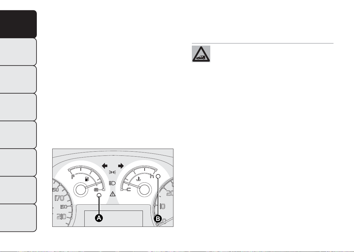
FUEL LEVEL GAUGE
The needle shows the amount of fuel left in the tank.
Warning light A fig. 10 switches on to indicate that
6 to 7 litres of fuel are left in the the tank.
E - tank empty.
F - tank full (see the description in paragraph "Vehicle
refuelling" in this chapter).
Do not travel with the tank nearly empty to prevent
damaging the catalytic converter.
KNOW YOUR
VEHICLE
SAFETY
ST
ARTING AND
DRIVING
WARNING LIGHTS
AND MESSAGES
IN AN EMERGENCY
SERVICING AND
MAINTENANCE
fig. 8
F0T0402
fig. 9
TECHNICAL
SPECIFICATIONS
INDEX
F0T0403
13
Page 15
KNOW YOUR
VEHICLE
IMPORTANT The needle will point to E and warning
light A will flash to indicate a fault in the system. If
this is the case, contact a Fiat Dealership to have the
system checked.
Warning light B fig. 10 switches on (together with a
message on the display) to indicate that the coolant
temperature is too high; in this case, stop the engine
and contact a Fiat Dealership.
ENGINE COOLANT TEMPERATURE GAUGE
SAFETY
The needle shows the temperature of the engine
coolant and starts supplying indications when the
fluid temperature exceeds approx. 50°C.
ST
ARTING AND
DRIVING
In normal use, the needle could assume different
positions within the scale, depending on the usage
conditions.
WARNING LIGHTS
AND MESSAGES
C - Low engine coolant temperature.
H - High engine coolant temperature.
IN AN EMERGENCY
SERVICING AND
MAINTENANCE
TECHNICAL
SPECIFICATIONS
If the needle for the engine coolant
temperature reaches the red area, stop
the engine immediately and contact a Fiat
Dealership.
14
INDEX
fig. 10
F0T0404
Page 16
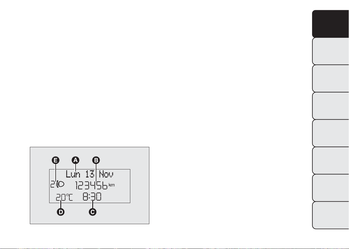
MULTIFUNCTION DISPLAY
The vehicle may be equipped with a multifunction
display that gives the driver useful information
depending on the previous settings.
Note When one of the doors is opened, the display
is activated showing the time and mileage for a few
seconds.
KNOW YOUR
VEHICLE
STANDARD SCREEN
The standard screen fig. 11 shows the following
information:
Date.
A
Odometer (distance covered in km or miles).
B
Time.
C
Outside temperature (not present on methane
D
vehicles, for which outside temperature is
displayed in trip menu, see "Trip computer").
Headlamp alignment position (only with dipped
E
headlamps on).
SAFETY
ST
ARTING AND
DRIVING
WARNING LIGHTS
AND MESSAGES
IN AN EMERGENCY
SERVICING AND
MAINTENANCE
TECHNICAL
SPECIFICATIONS
INDEX
fig. 11
F0T0019
15
Page 17
KNOW YOUR
VEHICLE
SAFETY
ST
ARTING AND
DRIVING
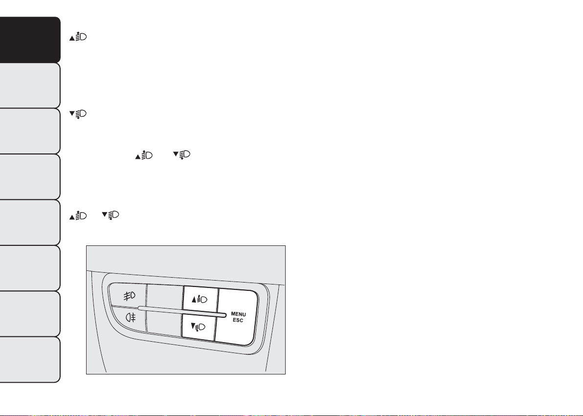
CONTROL BUTTONS
To scroll through the screen and the options
upwards or to increase the value displayed.
MENU ESC
Press briefly to access the menu and/or go to next
screen or confirm the chosen menu option.
Hold down to go back to the standard screen.
To scroll down through the displayed menu and
the related options or to decrease the value
displayed.
Setup menu
- in menus, to scroll up and down;
- in setting operations, to increase or decrease a
value.
Note Buttons
WARNING LIGHTS
AND MESSAGES
functions according to the following situations:
Adjusting headlight alignment
- with the dipped beam headlights on, press button
IN AN EMERGENCY
SERVICING AND
MAINTENANCE
TECHNICAL
SPECIFICATIONS
INDEX
16
and activate different
or to adjust headlight alignment.
fig. 12
F0T0449
Page 18
SETUP MENU
KNOW YOUR
VEHICLE
SAFETY
ST
ARTING AND
DRIVING
WARNING LIGHTS
AND MESSAGES
IN AN EMERGENCY
SERVICING AND
MAINTENANCE
fig. 13
F0T1032
TECHNICAL
SPECIFICATIONS
INDEX
17
Page 19
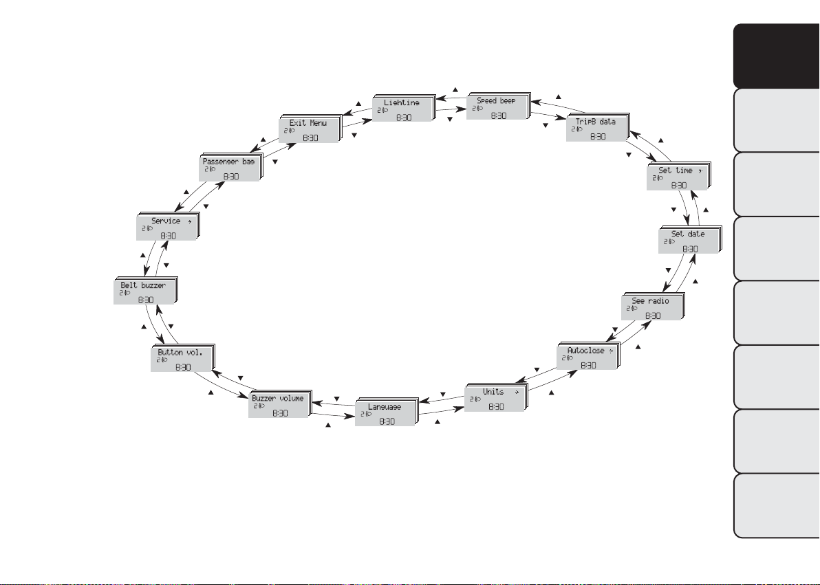
Setup menu function
KNOW YOUR
VEHICLE
ST
ARTING AND
DRIVING
WARNING LIGHTS
AND MESSAGES
IN AN EMERGENCY
SERVICING AND
MAINTENANCE
The menu fig. 13 comprises a series of functions in
"circular" arrangement, which can be selected by
pressing the
different operations and settings described in the
following paragraphs. A submenu is provided for
SAFETY
some items (clock and unit setting).
The setup menu can be activated by pressing the
MENU ESC button briefly.
Press buttons
options.
Management modes differ according to the option
selected.
Selecting an option from the main menu without a
submenu:
- briefly press MENU ESC to select the main menu
option you wish to set;
- press
new setting;
- a short press on button MENU ESC will store the
setting and then return to the same main menu
option that was first selected.
and buttons to access the
or to scroll the setup menu
or (with single presses) to select the
Selecting an option from the main menu with a
submenu:
- briefly press the MENU ESC button to display the
first submenu option;
- press
the submenu options;
- briefly press the MENU ESC button to select the
displayed submenu option and to open the relevant
setup menu;
- press
new setting for this submenu option;
- briefly press the MENU ESC button to store the
new setting and go back to the previous menu
option.
Selecting “Date” and “Set time”:
- briefly press MENU ESC to select the first value to
change (e.g. hours/minutes or year/month/day);
- press
new setting;
- briefly press MENU ESC to store the new setting
and go to the next setup menu option: if this is
the last one you will go back to the previous menu
option.
or (with single presses) to scroll all
or (with single presses) to select the
or (with single presses) to select the
TECHNICAL
SPECIFICATIONS
INDEX
18
Page 20

Hold down MENU ESC:
- to quit the set up menu if you are in the main
menu;
- to quit the main menu if you are in another point of
the menu (e.g. at submenu option setting level, at
submenu level or at main menu option setting level);
- to save only the settings already stored (and
confirmed by pressing the MENU ESC button).
The setup menu page is timed. Only the changes
already stored by pressing the MENU ESC button are
saved when you come out of the menu.
On the standard screen, briefly press MENU ESC to
start browsing.
Press
Note Only the short menu may be accessed for
reasons of safety while the vehicle is moving ("Speed
Beep" setting). Stop the vehicle to access the full
menu.
or to browse within the menu.
Adjusting the vehicle interior lighting
This function is available with the dipped beam
headlights on to adjust brightness of the instrument
panel, buttons and radio display.
To adjust the light intensity, proceed as follows:
❒ press the MENU ESC button briefly to make the
display flash the previously set level;
❒ press button
brightness level;
❒ press the MENU ESC button briefly to return to
the menu screen or give the button a long press
to return to the standard screen without storing.
Speed limit (Speed Beep)
This function is used to set the vehicle speed limit
(km/h or mph). When this limit is exceeded the
driver is immediately alerted (see “Warning lights
and messages” section).
To set the desired speed limit, proceed as follows:
- briefly press the MENU ESC button: the display will
show the words (Speed Beep);
- press
(On) or deactivation (Off);
- if the function is on, press
required speed limit and then press MENU ESC to
confirm;
or to select speed limit activation
and to set the required
or to select the
KNOW YOUR
VEHICLE
SAFETY
ST
ARTING AND
DRIVING
WARNING LIGHTS
AND MESSAGES
IN AN EMERGENCY
SERVICING AND
MAINTENANCE
TECHNICAL
SPECIFICATIONS
INDEX
19
Page 21
Note Setting is possible between 30 and 200 km/h,
KNOW YOUR
VEHICLE
ST
ARTING AND
DRIVING
WARNING LIGHTS
AND MESSAGES
IN AN EMERGENCY
SERVICING AND
MAINTENANCE
TECHNICAL
SPECIFICATIONS
or 20 and 125 mph, according to the previously
stored unit. See the "Setting the unit of
measurement" paragraph described below. The
setting will increase/decrease by five units each time
button
increase/decrease the setting rapidly. Complete
SAFETY
the setting by single pressing the button when you
approach the required value.
- press the MENU ESC button briefly to return to
the menu screen or give the button a long press
to return to the standard screen without storing.
To cancel the setting, proceed as follows:
- press the MENU ESC button briefly to make the
display flash (On);
- press
- press the MENU ESC button briefly to return to
the menu screen or give the button a long press
to return to the standard screen without storing.
INDEX
/ is pressed. Hold down / to
: (Off ) will flash on the display;
Trip B activation (tripB data)
With this function is possible to turn the Trip B
display (trip meter) on and off.
For more information see "Trip computer"
paragraph.
For activation/deactivation, proceed as follows:
- briefly press MENU ESC: On or Off will flash on
the display (depending on previous setting);
- press
- press the MENU ESC button briefly to return to
the menu screen or give the button a long press
to return to the standard screen without storing.
Setting the clock (Set time)
This function allows you to set the clock through
two submenus: “Time” and “Mode”.
To carry out the adjustment, proceed as follows:
- briefly press the MENU ESC button and two
submenus (Time and Format) are displayed;
– press
sub-menus;
- once you have selected a submenu, press MENU
ESC briefly;
- if selecting “Time”, briefly press MENU ESC - the
“hours” will flash on the display;
- press the
adjustment;
or to make your choice;
or to switch between the two
or button to make the
20
Page 22
- briefly press the MENU ESC button, which makes
the display flash the minutes;
- press the
adjustment;
- when you select “Mode”, pressing MENU ESC
makes the mode flash on the display;
- press the
selection in 24h or 12h mode.
When you have made the required adjustments,
press SET ESC to go back to the submenu screen or
hold the button down to go back to the main menu
screen without saving.
- hold down MENU ESC again to go back to the
standard screen or main menu, depending on which
point in the menu you have reached.
Set date (Set Date)
This function allows updating of the date (day month - year).
To update, proceed as follows:
- briefly press MENU ESC: the day (dd) will flash on
the display;
- press the
adjustment;
- briefly press MENU ESC: the month (mm) will flash
on the display;
- press the
adjustment;
or button to make the
or button to carry out the
or button to make the
or button to make the
- briefly press MENU ESC: the year (yyyy) will flash
on the display;
- press the
adjustment.
Note The setting increases or decreases by one unit
each time
pressed causes an automatic speed increase/
decrease. Complete the setting by single pressing the
button when you approach the required value.
- press the MENU ESC button briefly to return to
the menu screen or give the button a long press
to return to the standard screen without storing.
Audio information (See radio)
This function is used to display radio information.
- Radio: selected radio station frequency or RDS
message, automatic tuning activation or AutoSTore;
- Audio CD, MP3 CDs: track number;
- CD Changer: CD number and track number;
To show the car radio information on the display
(on) or not (off ), proceed as follows:
- briefly press MENU ESC: On or Off will flash on
the display (depending on previous setting);
- press
- press the MENU ESC button briefly to return to
the menu screen or give the button a long press
to return to the standard screen without storing.
or button to make the
or is pressed. Keeping the button
or to make your choice;
KNOW YOUR
VEHICLE
SAFETY
ST
ARTING AND
DRIVING
WARNING LIGHTS
AND MESSAGES
IN AN EMERGENCY
SERVICING AND
MAINTENANCE
TECHNICAL
SPECIFICATIONS
INDEX
21
Page 23

Automatic central door locking with vehicle
KNOW YOUR
VEHICLE
ST
ARTING AND
DRIVING
WARNING LIGHTS
AND MESSAGES
IN AN EMERGENCY
SERVICING AND
MAINTENANCE
TECHNICAL
SPECIFICATIONS
running (Autoclose)
After activation (On) this function allows the
automatic locking of the doors to be activated when
the speed exceeds 20 km/h.
To activate (On) or deactivate (Off) this function,
SAFETY
proceed as follows:
- press the MENU ESC button briefly: the display will
show a submenu;
- briefly press MENU ESC: On or Off will flash on
the display (depending on previous setting);
- press
- briefly press the MENU ESC button to go back to
the submenu screen or hold the button down to
go back to the main menu screen without saving;
- hold down MENU ESC again to go back to the
standard screen or main menu, depending on which
point in the menu you have reached.
INDEX
or to make your choice;
Setting the unit of measurement
With this function it is possible to set the
measurement units through three submenus:
“Distance”, “Consumption” and “Temperature”.
To set the desired measurement unit, proceed
as follows:
- briefly press MENU ESC to display the three
submenus;
- press
submenus;
- once the submenu to be modified has been
selected, briefly press the MENU ESC button;
- if the submenu “Distances” is entered: by briefly
pressing SET ESC the display shows "km" or "mi"
depending on the previous setting;
- press
- when you select “Consumption”, pressing SET ESC
makes km/l, l/100km or mpg appear on the display
(depending on the previous setting);
If the distance unit of measurement stored is km, the
display allows the setting of the measurement unit
(km/l or l/100km) referring to the amount of fuel
consumed.
If the distance unit of measurement stored is mi, the
display shows the amount of fuel consumed in mpg.
- press
- if the submenu “Distances” is entered: by briefly
pressing SET ESC the display shows "km" or "mi"
depending on the previous setting;
or to switch between the three
or to make your choice;
or to make your choice;
22
Page 24
- press or to make your choice;
When you have made the required adjustments,
press SET ESC to go back to the submenu screen or
hold the button down to go back to the main menu
screen without saving.
- hold down MENU ESC again to go back to the
standard screen or main menu, depending on which
point in the menu you have reached.
Selecting the language (Language)
Display messages can be shown in different
languages: Italian, German, English, Spanish, French,
Portuguese, Turkish and Dutch.
To set the required language, proceed as follows:
- briefly press MENU ESC: the previously set
language will flash on the display;
- press
- press the MENU ESC button briefly to return to
the menu screen or give the button a long press
to return to the standard screen without storing.
or to make your choice;
Adjusting the failure/warning buzzer volume
(Alert Volume)
With this function is possible to adjust (to eight
levels) the volume of the acoustic signal which
sounds in the event of alerts and warning.
To set the desired volume, proceed as follows:
- briefly press MENU ESC: the previously set volume
level will flash on the display;
- press the
adjustment;
- press the MENU ESC button briefly to return to
the menu screen or give the button a long press
to return to the standard screen without storing.
Adjusting the button volume (Button Vol.)
This function may be used to adjust (over 8 levels)
the volume of the noise made when the MENU ESC,
and buttons are pressed.
To set the desired volume, proceed as follows:
- briefly press MENU ESC: the previously set volume
level will flash on the display;
- press the
adjustment;
- press the MENU ESC button briefly to return to
the menu screen or give the button a long press
to return to the standard screen without storing.
or button to make the
or button to make the
KNOW YOUR
VEHICLE
SAFETY
ST
ARTING AND
DRIVING
WARNING LIGHTS
AND MESSAGES
IN AN EMERGENCY
SERVICING AND
MAINTENANCE
TECHNICAL
SPECIFICATIONS
INDEX
23
Page 25
SBR buzzer reactivation (Belt Buzzer)
KNOW YOUR
VEHICLE
ST
ARTING AND
DRIVING
WARNING LIGHTS
AND MESSAGES
IN AN EMERGENCY
SERVICING AND
MAINTENANCE
TECHNICAL
SPECIFICATIONS
This function can be displayed only after a Fiat
Dealership has deactivated the SBR system (see “SBR
system” in the “Safety” section).
Scheduled Servicing (Service)
SAFETY
This function is used to display information related to
regular servicing intervals.
This information can be consulted as follows:
- briefly press MENU ESC: service intervals in km or
mi, depending on the previous setting, will be
displayed (see “Setting the unit of measurement”);
- press the MENU ESC button briefly to return
to the menu screen or hold the button down to
return to the standard screen.
Note The “Scheduled Servicing Plan” requires the
vehicle to be serviced every 30,000 km (or 18,000
mi). This indication will appear automatically, with
the key at MAR, starting from 2,000 km (or 1,240
mi) and will be displayed every 200 km (or 124 mi).
Below 200 km the signals become more frequent.
The display will be in km or miles according to
the unit of measurement set. When the next service
is close, when the ignition is turned ON the word
"Service" appears in the display followed by the
remaining number of kilometres/miles. Go to a Fiat
Dealership, where the "Scheduled Service Plan"
operations will be performed and the message will
be reset.
INDEX
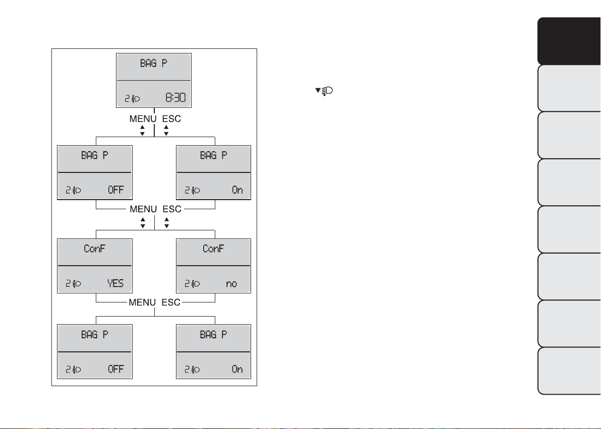
Passenger airbag and side bag activation/
deactivation (Passenger bag)
(for versions/markets, where provided)
This function is used to activated/deactivated the
passenger's airbag.
Proceed as follows fig. 14:
❒ press MENU ESC and, after the message BAG P
OFF (to deactivate) or BAG P On (to activate) is
displayed by pressing buttons
MENU ESC again;
❒ the confirmation request message will appear on
the display;
❒ use the
(to confirm the activation/deactivation) or (No)
(to cancel);
❒ press the MENU ESC button briefly; a selection
confirmation message will be displayed after which
the program returns to the menu screen.
Alternatively, press and hold down the button to
return to the standard screen without storing.
or menu buttons to select (Yes)
and , press
24
Page 26
Exit menu
This function closes the settings listed on the menu
screen.
Briefly press MENU ESC to go back to the standard
screen without saving.
Press
to return to the first menu option (Speed
Beep).
KNOW YOUR
VEHICLE
SAFETY
ST
ARTING AND
DRIVING
WARNING LIGHTS
AND MESSAGES
IN AN EMERGENCY
SERVICING AND
MAINTENANCE
fig. 14
TECHNICAL
SPECIFICATIONS
INDEX
F0T1028
25
Page 27
TRIP COMPUTER
KNOW YOUR
VEHICLE
ST
ARTING AND
DRIVING
WARNING LIGHTS
AND MESSAGES
IN AN EMERGENCY
SERVICING AND
MAINTENANCE
TECHNICAL
SPECIFICATIONS
General features
The Trip computer is used to display information on
vehicle operation when the ignition key is turned
to MAR. This function allows you to define two
SAFETY
separate trips, called "Trip A" and "Trip B", for
monitoring the "complete mission" (journey) of the
vehicle in a reciprocally independent manner. Both
functions can be reset (start of a new journey).
“Trip A” is used to display the values relating to:
❒ Outside temperature (for versions with outside
temperature sensor and methane-powered
vehicles)
❒ Range
❒ Distance travelled
❒ Average consumption
❒ Current consumption
❒ Average speed
❒ Travel time (driving time).
"Trip B", available on multifunction display only, is
used to display the values relating to:
❒ Distance travelled B
❒ Average consumption B
❒ Average speed B
❒ Travel time B (driving time).
INDEX
“Trip B” may be disabled (see “Activating
Trip B”). “Range” and “Instant
consumption" parameters cannot be
reset.
Values displayed
Range
This indicates the distance which may be travelled
with the fuel in the tank assuming that driving style
does not change. The display will show the reading
“----“ when the following events take place:
❒ range is lower than 50 km (or 30 mi)
❒ vehicle is left parked with the engine running for a
long time.
IMPORTANT The range can be affected by several
factors: driving style (see “Driving style” in the
“Starting and driving” section), type of route
(motorway, towns and cities, mountain roads, etc.),
conditions of use (load, tyre pressures, etc.). Trip
planning must therefore take the above into account.
Distance travelled
This value shows the distance covered from the start
of the new journey.
26
Page 28
Average consumption
This value shows the approximate average fuel
consumption from the start of the new journey.
Current consumption
Indicates the fuel consumption. The value is
constantly updated. The message “----” will appear
on the display if the car is parked with the engine
running.
Average speed
This value shows the average speed of the vehicle
based on the overall time elapsed since the start of
the new journey.
Journey time
Time elapsed since the start of the new journey.
IMPORTANT If there is no information, the Trip
computer displays "----" in place of the value. When
normal operating conditions are restored, the
counting of the various values is resumed, without
either zeroing the values displayed prior to the
problem, or starting a new journey.
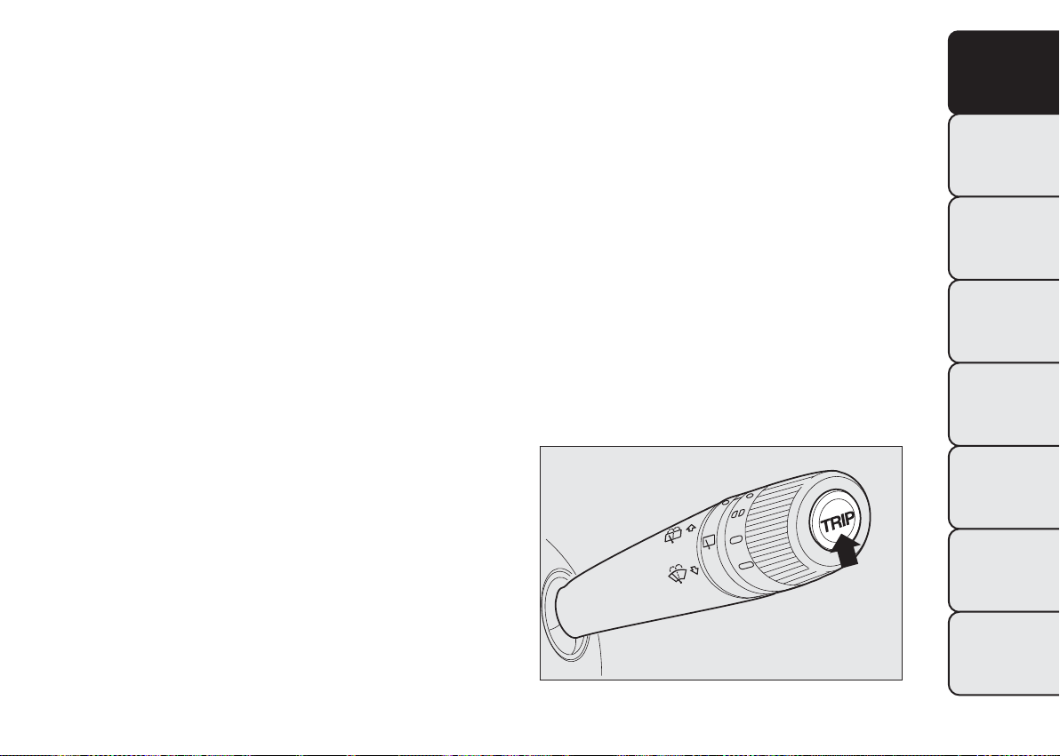
ControlTRIP button
The TRIP button, located on the right hand lever fig.
15 allows you to view the previously described
values as well as zero them to begin a new mission
when the ignition key is in the MAR position:
❒ press briefly to display the different values;
❒ long push to reset and then start a new journey.
New mission
This begins after a reset:
❒ “manual” resetting by the user, by pressing the
relevant button;
❒ automatically when the distance travelled reaches
9,999.9 km (miles) or when the journey time
reaches 99.59:59 (99 hours and 59 minutes);
❒ disconnection/reconnection of the battery.
KNOW YOUR
VEHICLE
SAFETY
ST
ARTING AND
DRIVING
WARNING LIGHTS
AND MESSAGES
IN AN EMERGENCY
SERVICING AND
MAINTENANCE
fig. 15
TECHNICAL
SPECIFICATIONS
INDEX
F0T0038
27
Page 29
IMPORTANT The reset operation when “Trip A”
KNOW YOUR
VEHICLE
details are being displayed only resets the
information associated with this function.
IMPORTANT The reset operation when “Trip B”
details are being displayed resets only the
information associated with this function.
SAFETY
Start of journey procedure
ST
ARTING AND
DRIVING
With ignition key at MAR, press and hold the TRIP
button for more than 2 seconds to reset.
Exit Trip
WARNING LIGHTS
AND MESSAGES
You can automatically exit the TRIP function once all
the values have been displayed, or by holding the
MENU ESC button down for more than 1 second.
IN AN EMERGENCY
SERVICING AND
MAINTENANCE
SEATS
FRONT SEATS
WARNING
All adjustments must be made with the
v
ehicle stationary.
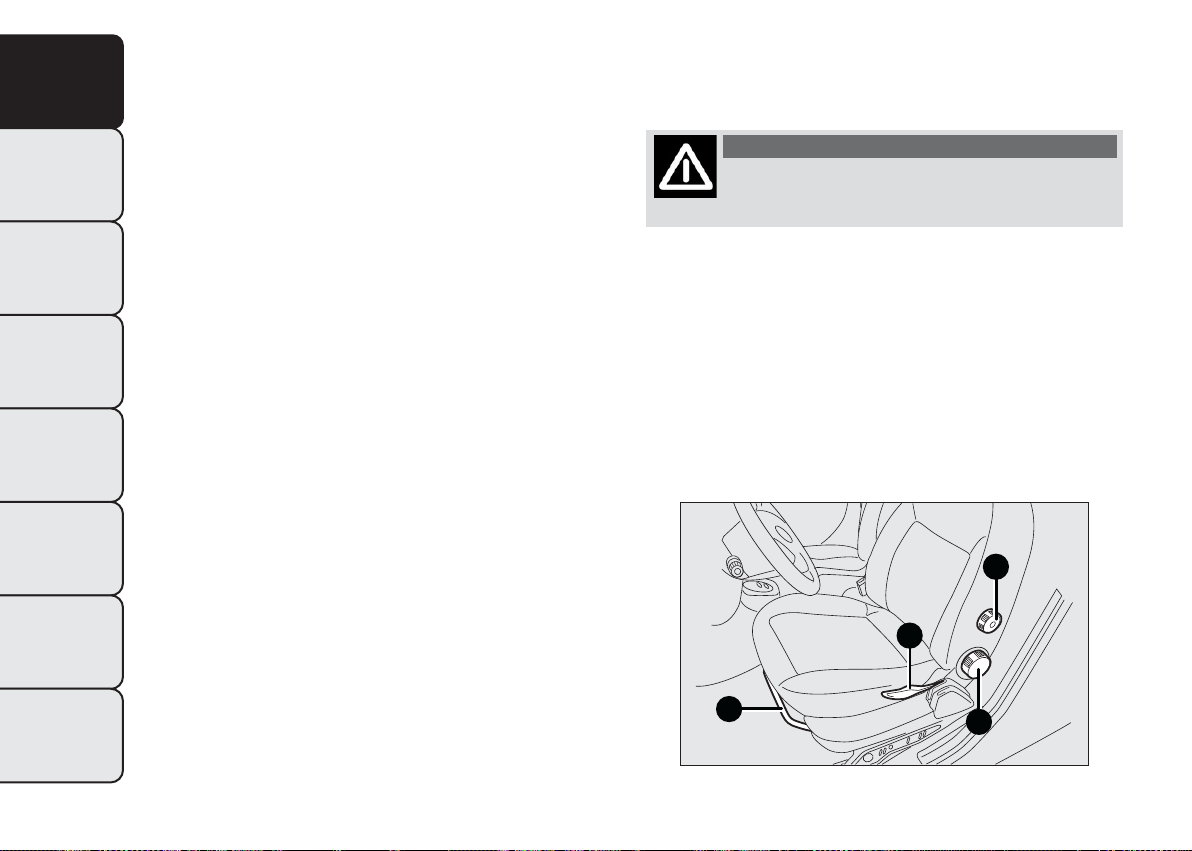
Lengthwise adjustment
Lift lever A fig. 16and push the seat forwards or
backwards: in the driving position your arms should
rest on the rim of the steering wheel.
D
TECHNICAL
SPECIFICATIONS
INDEX
28
fig. 16
C
A
B
F0T0153
Page 30
WARNING
Once you have released the adjustment
le
ver, always check that the seat is
locked on the guides by trying to move it back
and forth. If it is not locked, the seat may move
unexpectedly and make you lose control of
the vehicle.
Backrest angle adjustment
Turn knob B fig. 16.
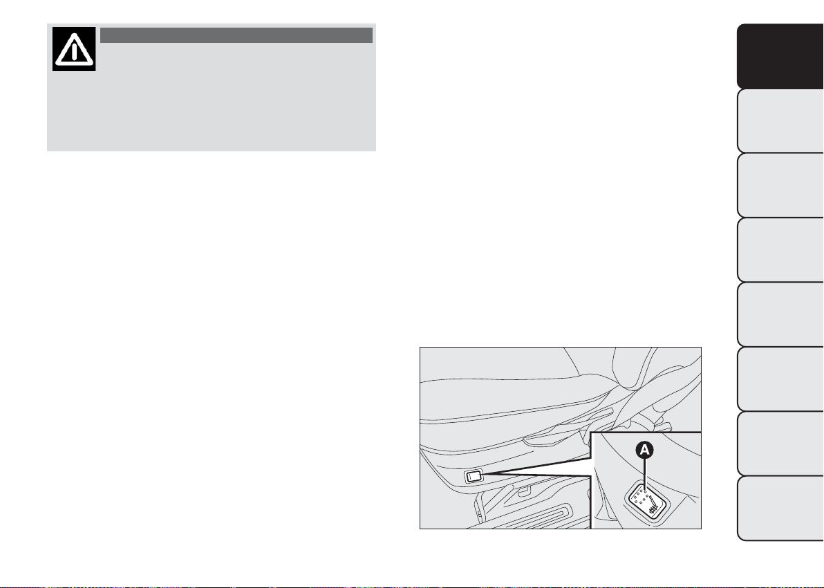
Seat heating
(for versions/markets, where provided)
With the key at MAR, press button
A fig. 17 to turn the function on/off.
When the function is enabled, the LED on the
button turns on.
FOLDAWAY PASSENGER SEAT
(for versions/markets, where provided)
The passenger seat can be folded away on some
versions.
KNOW YOUR
VEHICLE
SAFETY
ST
ARTING AND
DRIVING
Height adjustment (driver only)
(for versions/markets, where provided)
Operate lever C fig. 16 to lift or lower the rear part
of the cushion to achieve the most comfortable
driving position.
IMPORTANT Adjustment must be carried out only
when seated in the relevant seat.
Driver seat lumbar adjustment
(for versions/markets, where provided)
Turn knob D fig. 16 to adjust the backrest support.
IMPORTANT Move the seat only when there are no
rear passengers.
fig. 17
F0T0205
WARNING LIGHTS
AND MESSAGES
IN AN EMERGENCY
SERVICING AND
MAINTENANCE
TECHNICAL
SPECIFICATIONS
INDEX
29
Page 31

Folding the seat
KNOW YOUR
VEHICLE
To fold the seat, proceed as follows:
❒ open the passenger door;
❒ pull lever A fig. 18 and fold the backrest forwards
in the direction indicated by the arrow;
SAFETY
ST
ARTING AND
DRIVING
WARNING LIGHTS
AND MESSAGES
IN AN EMERGENCY
SERVICING AND
MAINTENANCE
fig. 18
❒ then push the backrest B fig. 19 down: the seat is
now completely folded over on itself into the
"table" position;
❒ pull flap C fig. 19 and push the backrest down
further: the seat is now completely folded away.
Repositioning the seat
To return the seat back to its normal position,
proceed as follows:
❒ take tab C fig. 19 and lift the backrest up;
❒ operate levers B fig. 20 and further lift the seat
upwards.
F0T0235
TECHNICAL
SPECIFICATIONS
INDEX
30
fig. 19
F0T0457
fig. 20
F0T0237
Page 32

WARNING
When the passenger seat is folded away,
t
he space created cannot be used for
loading.When the vehicle is in motion, you are
therefore advised to remove or secure any
objects that might interfere with the driver. If
there is no partition between the cab and
the load compartment, tall objects or packages
may take up part of the passenger area. Make
sure that these items are well secured by using
the available hooks and that they cannot
interfere with the driver.
ACCESSING REAR SEATS (Combi versions)
Open one of the two sliding side doors to access the
rear seats (see "Doors" in this section).
FIXED PARTITION (for N1 4 seat
versions)
This is located behind the backrest of the rear seats
fig. 21.
KNOW YOUR
VEHICLE
SAFETY
ST
ARTING AND
DRIVING
WARNING LIGHTS
AND MESSAGES
IN AN EMERGENCY
SERVICING AND
MAINTENANCE
fig. 21
TECHNICAL
SPECIFICATIONS
INDEX
F0T0340
31
Page 33

HEADREST
KNOW YOUR
VEHICLE
ST
ARTING AND
DRIVING
WARNING LIGHTS
AND MESSAGES
IN AN EMERGENCY
SERVICING AND
MAINTENANCE
FRONT
These are height-adjustable and lock into place
automatically fig. 22.
SAFETY
❒ Upward adjustment: lift the headrest until it locks.
❒ Downward adjustment: press button A fig. 22and
lower the headrest.
WARNING
All adjustments must be carried out only
wi
th the vehicle stationary and the
engine off. Headrests must be adjusted so that
the head, rather than the neck, rests on them.
Only in this case they can protect your head
correctly.To maximise the protective action
provided by the headrest, adjust the seat back
so that your trunk is upright and keep your
head as close to the headrest as possible.
TECHNICAL
SPECIFICATIONS
INDEX
32
fig. 22
F0T0053
Page 34

REAR
(for versions/markets, where provided)
Lift up to use.
To put the headrests away, press buttons A fig. 23 fig.
24 and push them down into the backrest.
fig. 23
F0T0054
To extract the headrests, raise them until you hear
the click (which indicates they are in "all extracted"
position).
IMPORTANT The headrests must always be in the
"all extracted" position when the rear seats are
in use.
KNOW YOUR
VEHICLE
SAFETY
ST
ARTING AND
DRIVING
WARNING LIGHTS
AND MESSAGES
IN AN EMERGENCY
SERVICING AND
MAINTENANCE
fig. 24 - N1 versions (4 seats)
TECHNICAL
SPECIFICATIONS
INDEX
F0T0341
33
Page 35

STEERING WHEEL
KNOW YOUR
VEHICLE
ST
ARTING AND
DRIVING
WARNING LIGHTS
AND MESSAGES
IN AN EMERGENCY
SERVICING AND
MAINTENANCE
The height and axial position of the steering wheel
can be adjusted on some versions.
To carry out the adjustment, proceed as follows:
❒ release lever A fig. 25 by pushing it forwards
SAFETY
(position 1);
❒ adjust the steering wheel;
❒ lock lever A by pulling it towards the steering
wheel (position 2).
engine off.
WARNING
All adjustments must be carried out only
wi
th the vehicle stationary and the
WARNING
It is absolutely forbidden to carry out
an
y after-market operation involving
steering system or steering column
modifications (e.g. installation of anti-theft
device) that could badly affect performance and
safety, invalidate t he warranty and also result
in the vehicle failing to comply with regulations.
TECHNICAL
SPECIFICATIONS
INDEX
34
fig. 25
F0T0040
Page 36

REAR-VIEW MIRRORS
INTERIOR REAR-VIEW MIRROR
(for versions/markets, where provided)
The mirror is fitted with a safety device that causes
its release in the event of a violent impact with
the passenger.
Lever A fig. 26can be used to move the mirror to
two different positions: normal or antiglare.
WING MIRRORS
Manual mirror folding
When required (for example when the shape causes
difficulty in narrow spaces), the mirrors can be
folded by moving them from position A fig. 27 to
position B.
WARNING
When driving, the mirrors shall always
be
in position A.fig. 27
WARNING
The door mirrors, being curved, slightly
al
ter the perception of distance.
KNOW YOUR
VEHICLE
SAFETY
ST
ARTING AND
DRIVING
WARNING LIGHTS
AND MESSAGES
IN AN EMERGENCY
SERVICING AND
MAINTENANCE
fig. 26
F0T0027
fig. 27
TECHNICAL
SPECIFICATIONS
INDEX
F0T0042
35
Page 37

Manual adjustment
KNOW YOUR
From inside, use device A fig. 28.
VEHICLE
Electric adjustment
(for versions/markets, where provided)
SAFETY
You can only adjust the door mirrors electrically
when the ignition key is turned to MAR.
ST
ARTING AND
DRIVING
WARNING LIGHTS
AND MESSAGES
IN AN EMERGENCY
SERVICING AND
MAINTENANCE
Proceed as follows:
❒ select the required mirror with switch A fig. 29
(right or left);
❒ move switch A to position B and manipulate it to
adjust the left wing mirror;
❒ move switch A to position D and manipulate it to
adjust the right wing mirror.
Once you have finished the adjustment, return switch
A to intermediate locking position C.
TECHNICAL
SPECIFICATIONS
INDEX
36
fig. 28
F0T0194
fig. 29
F0T0041
Page 38

HEATING AND VENTILATION SYSTEM
AIR VENTS
KNOW YOUR
VEHICLE
SAFETY
ST
ARTING AND
DRIVING
WARNING LIGHTS
AND MESSAGES
IN AN EMERGENCY
SERVICING AND
MAINTENANCE
fig. 30
1. Upper fixed vent 2. Adjustable central vents 3. Fixed side vents 4. Adjustable side vents 5. Foot well vents
F0T0148
TECHNICAL
SPECIFICATIONS
INDEX
37
Page 39

CENTRAL AND SIDE VENTS
KNOW YOUR
VEHICLE
A Adjustable side vent fig. 31
B Side window fixed vent fig. 31
C Adjustable central ventsfig. 32
To use vents A and C, adjust them as required.
SAFETY
ST
ARTING AND
DRIVING
WARNING LIGHTS
AND MESSAGES
IN AN EMERGENCY
SERVICING AND
MAINTENANCE
fig. 31
F0T0031
HEATING AND VENTILATION
COMMANDS
The main heating and ventilation commands are
listed below fig. 33:
air temperature adjustment knob (hot/cold air
A
mixing)
air recirculation on/off slider
B
fan activation knob
C
air distribution knob.
D
TECHNICAL
SPECIFICATIONS
INDEX
38
fig. 32
F0T0030
fig. 33
F0T0074
Page 40

TEMPERATURE COMFORT
Knob D enables fresh air to reach all parts of the
passenger compartment through five options:
delivers air from the central and side vents;
warms the feet and keeps the face cool (bi-level
function)
allows the passenger compartment to be
warmed more quickly;
warms up the passenger compartment and
demists the windscreen at the same time;
demists and defrosts the windscreen and front
side windows.
HEATING
Proceed as follows:
❒ turn knob A all to the right (to
❒ turn knob C to the required speed
❒ turn knob D to:
to warm the feet and demist the windscreen at
❒
the same time
to send air to the feet and introduce fresher air
❒
from the central and dashboard vents
to warm up quickly.
❒
)
FAST HEATING
Proceed as follows:
❒ close all the vents in the dashboard
❒ turn knob A to
❒ turn knob C to 4
❒ turn knob D to
RAPID WINDSCREEN AND FRONT SIDE
WINDOWS DEMISTING/DEFROSTING
(MAX-DEF function)
Proceed as follows:
❒ turn knob A to
❒ turn knob C to 4
❒ turn knob D to
❒ take the slider B to .
After demisting/defrosting, operate the controls as
normal to restore the required comfort conditions.
Window demisting
In the event of considerable external moisture
and/or rain and/or large differences in the
temperature inside and outside the passenger
compartment, perform the following preventive
window demisting procedure:
❒ take the slider B to
❒ turn knob A to
KNOW YOUR
VEHICLE
SAFETY
ST
ARTING AND
DRIVING
WARNING LIGHTS
AND MESSAGES
IN AN EMERGENCY
SERVICING AND
MAINTENANCE
TECHNICAL
SPECIFICATIONS
INDEX
39
Page 41

❒ turn knob C to 2
KNOW YOUR
VEHICLE
ST
ARTING AND
DRIVING
WARNING LIGHTS
AND MESSAGES
IN AN EMERGENCY
SERVICING AND
MAINTENANCE
❒ turn knob D to
position
steaming up.
REGULATINGTHE FAN SPEED
SAFETY
To ventilate the passenger compartment properly,
proceed as follows:
❒ fully open the central and side air vents
❒ knob A turned to blue section
❒ take the slider B to
❒ turn knob C to the required speed
❒ turn knob D to
with the option of moving to
if there is no sign of the windows
INTERNAL AIR RECIRCULATION
ACTIVATION
Take the slider B to
It is advisable to switch the internal air recirculation
on while standing in queues or in tunnels to prevent
the introduction of polluted air.
Do not use the function for a long time, particularly
if there are several passengers on board, to prevent
the windows from steaming up.
IMPORTANT The internal air recirculation system
makes it possible to reach the required heating
or cooling conditions more quickly. Do not use the
internal air recirculation function on rainy/cold
days to avoid the possibility of the windows misting.
.
TECHNICAL
SPECIFICATIONS
INDEX
40
Page 42

DEMISTING/DEFROSTING OF HEATED
REAR WINDSCREEN AND DOOR MIRRORS
(for versions/markets, where provided)
Press button
fig. 34 to activate the function. The
LED on the button comes on to indicate activation.
Press
again to disable the function in advance.
IMPORTANT Do not apply stickers on the inside of
the rear window over the heating filaments to avoid
damage that might cause it to stop working properly.
MANUAL CLIMATE CONTROL
SYSTEM
(for versions/markets, where provided)
COMMANDS
The main heating and ventilation controls are listed
below fig. 35:
air temperature adjustment knob (hot/cold air
A
mixing);
internal air recirculation on/off cursor;
B
fan and climate control system on/off knob;
C
air distribution knob.
D
TEMPERATURE COMFORT
Knob D enables fresh air to reach all parts of the
passenger compartment through five options:
delivers air from central and side vents
KNOW YOUR
VEHICLE
SAFETY
ST
ARTING AND
DRIVING
WARNING LIGHTS
AND MESSAGES
IN AN EMERGENCY
SERVICING AND
MAINTENANCE
fig. 34
F0T0048
fig. 35
TECHNICAL
SPECIFICATIONS
INDEX
F0T0029
41
Page 43

KNOW YOUR
VEHICLE
SAFETY
warms the feet and keeps the face cool (bi-level
function)
warms up the passenger compartment faster
warms up the passenger compartment and
demists the windscreen at the same time
demists and defrosts the windscreen and front
side windows.
FAST HEATING
Proceed as follows:
❒ close all the vents in the dashboard
❒ turn knob A to
❒ turn knob C to
❒ turn knob D to
HEATING
ST
ARTING AND
DRIVING
WARNING LIGHTS
AND MESSAGES
IN AN EMERGENCY
SERVICING AND
MAINTENANCE
TECHNICAL
SPECIFICATIONS
Proceed as follows:
❒ turn knob A all to the right (to
❒ turn knob C to the required speed
❒ turn knob D to:
❒
the same time
❒
from the central and dashboard vents
❒
INDEX
42
)
to warm the feet and demist the windscreen at
to send air to the feet and introduce fresher air
to warm up quickly.
RAPID WINDSCREEN AND FRONT SIDE
WINDOWS DEMISTING/DEFROSTING
(MAX-DEF function)
Proceed as follows:
❒ turn knob A to
❒ turn knob C to
❒ turn knob D to
❒ take the slider B to .
After demisting/defrosting, operate the controls as
normal to restore the required comfort.
IMPORTANT The climate control system is very
useful for faster demisting because it dries the air.
Adjust the controls as described above and engage
the climate control by pressing knob C.
Page 44

Window demisting
In the event of considerable external moisture
and/or rain and/or large differences in the
temperature inside and outside the passenger
compartment, perform the following preventive
window demisting procedure:
❒ take the slider B to
❒ turn knob A to
❒ turn knob C to 2
❒ turn knob D to
position
steaming up.
REGULATINGTHE FAN SPEED
To ventilate the passenger compartment properly,
proceed as follows:
❒ fully open the central and side air vents
❒ knob A turned to blue section
❒ take the slider B to
❒ turn knob C to the required speed
❒ turn knob D to
if there is no sign of the windows
with the option of moving to
INTERNAL AIR RECIRCULATION
ACTIVATION
Take the slider B to
It is advisable to switch the internal air recirculation
on while standing in queues or in tunnels to prevent
the introduction of polluted air.
Do not use the function for a long time, particularly
if there are several passengers on board, to prevent
the windows from steaming up.
IMPORTANT IMPORTANT The air recirculation
system makes it possible to reach the required
heating or cooling conditions faster. Do not use the
air recirculation function on rainy/cold days as it
would considerably increase the possibility of the
windows misting.
CLIMATE CONTROL (cooling)
Proceed as follows:
❒ knob A turned to blue section
❒ turn knob C to
❒ take the slider B to
❒ turn knob D to
❒ press knob C.
Adjusting cooling
Proceed as follows:
❒ take the slider B to
.
KNOW YOUR
VEHICLE
SAFETY
ST
ARTING AND
DRIVING
WARNING LIGHTS
AND MESSAGES
IN AN EMERGENCY
SERVICING AND
MAINTENANCE
TECHNICAL
SPECIFICATIONS
INDEX
43
Page 45

❒ turn knob A rightwards to increase the
KNOW YOUR
VEHICLE
temperature
❒ turn knob C leftwards to reduce the fan speed.
DEMISTING/DEFROSTING OF HEATED
REAR WINDSCREEN AND DOOR MIRRORS
SAFETY
(for versions/markets, where provided)
Press button
LED on the button comes on to indicate activation.
ST
ARTING AND
DRIVING
Press
IMPORTANT Do not apply stickers on the inside of
the rear window over the heating filaments to avoid
WARNING LIGHTS
damage that might cause it to stop working properly.
AND MESSAGES
IN AN EMERGENCY
SERVICING AND
MAINTENANCE
SYSTEM MAINTENANCE
Run the climate control system for at least 10
minutes every month during the winter. Have the
system inspected at a Fiat Dealership before the
summer.
fig. 36 to activate the function. The
again to disable the function in advance.
TECHNICAL
SPECIFICATIONS
INDEX
44
fig. 36
F0T0048
Page 46

EXTERIOR LIGHTS
The left stalk fig. 37includes the exterior light
controls.
The exterior lights can only be switched on when
the ignition key is in MAR.
The instrument panel and the various controls on
the dashboard will be lit up when the exterior lights
are switched on.
LIGHTS OFF
Ring turned to position
SIDE LIGHTS - TAIL LIGHTS
Turn the ring to position
warning light
will come on.
.
. The instrument panel
PARKING LIGHTS
These lights can be turned on only with the ignition
key at STOP or extracted by turning the ring on
the left stalk first to position
and then to positions
or .
The instrument panel warning light
will come on.
Actuate the direction indicator stalk to select the
side of the lights (right or left).
DIPPED BEAM HEADLIGHTS
Turn the ring to position
warning light
will come on.
. The instrument panel
MAIN BEAM HEADLIGHTS
With the ring in position
, pull the stalk towards
the steering wheel (2nd unstable position). The
instrument panel warning light
will come on.
To turn the main beams off, pull the stalk towards
the steering wheel again (dipped beams will turn on).
KNOW YOUR
VEHICLE
SAFETY
ST
ARTING AND
DRIVING
WARNING LIGHTS
AND MESSAGES
IN AN EMERGENCY
SERVICING AND
MAINTENANCE
fig. 37
TECHNICAL
SPECIFICATIONS
INDEX
F0T0430
45
Page 47

FLASHING THE HEADLIGHTS
KNOW YOUR
VEHICLE
Pull the stalk towards the steering wheel (1st
unstable position) regardless of the position of the
control.
The instrument panel warning light
SAFETY
DIRECTION INDICATORS
Move the stalk to position fig. 38 (unstable):
ST
ARTING AND
DRIVING
❒ up (position 1): to activate the right direction
indicator;
❒ down (position 2): to activate the left direction
indicator.
WARNING LIGHTS
AND MESSAGES
Warning light
panel.
Direction indicators switch off automatically when
the vehicle is back in a straight line.
IN AN EMERGENCY
SERVICING AND
MAINTENANCE
will come on.
or will blink on the instrument
If you want the indicator to flash briefly to show that
you are about to change lane, move the stalk up or
down without it clicking into position. When
released, the stalk will return to its default position.
Lane change function
If you wish to signal a lane change, put the left stalk
in the temporary position for less than half a second.
The direction indicator on the selected side will
flash three times and then switch off automatically.
TECHNICAL
SPECIFICATIONS
INDEX
46
fig. 38
F0T0431
Page 48

“FOLLOW ME HOME” DEVICE
This device lights up the space in front of the vehicle
for a short time.
Activation
With the ignition key in the STOP position or
extracted, pull the stalk towards the steering wheel
and move it within 2 minutes of the engine switching
off.
Each time the stalk is moved, the lights stay on for an
extra 30 seconds up to a maximum of 210 seconds;
then the lights are switched off automatically.
Each time the stalk is moved, instrument panel
warning light
comes on and the corresponding
message will appear on the display (see “Warning
lights and messages”) for as long as the function
remains on. The light comes on when the stalk is
first moved and stays on until the function is
automatically deactivated. Each movement of the
stalk increases only the amount of time the lights
stay on.
Deactivation
Keep the stalk pulled towards the steering wheel for
more than 2 seconds.
WINDOW CLEANING
The right stalk fig. 39 controls windscreen
wiper/washer and heated rear window wiper/washer
operation (for versions/markets, where provided).
WINDSCREEN WIPER/WASHER
This only operates with the ignition turned to MAR.
The right stalk can assume five different positions:
windscreen wiper still.
intermittent operation.
continuous slow flick.
continuous fast flick.
Move the stalk to position fig. 39 (unstable) to limit
operation to the time for which the stalk is held
in this position.
When released, the stalk will return to its default
position and the wiper will be automatically stopped.
KNOW YOUR
VEHICLE
SAFETY
ST
ARTING AND
DRIVING
WARNING LIGHTS
AND MESSAGES
IN AN EMERGENCY
SERVICING AND
MAINTENANCE
TECHNICAL
SPECIFICATIONS
fig. 39
INDEX
F0T0432
47
Page 49

With the twist switch at , the windscreen wiper
KNOW YOUR
VEHICLE
ST
ARTING AND
DRIVING
WARNING LIGHTS
AND MESSAGES
IN AN EMERGENCY
SERVICING AND
MAINTENANCE
TECHNICAL
SPECIFICATIONS
will automatically adapt to the speed of the vehicle.
With the windscreen wipers working, if reverse gear
is engaged, the rear window wiper is automatically
activated.
SAFETY
windscreen wipers may be subjected to excessive
stress, prompting intervention from the motor
protection which prevents operation for a few
seconds. Contact the Fiat Dealership if operation
is not restored.
“Smart washing” function
Pull the stalk towards the steering wheel (temporary
position) to operate the windscreen washer jet.
Keeping the stalk pulled for more than half a second,
with just one movement it is possible to operate
the washer jet and the wiper at the same time.
The wiper stops working three strokes after the
stalk is released.
A further stroke after approx. 6 seconds completes
the wiping cycle.
Do not use the windscreen wipers to
remove layers of snow or ice from t he
windscreen. In such conditions, the
REAR WINDOW WIPER/WASHER
(for versions/markets, where provided)
This only operates with the ignition turned to MAR.
Activation
Turn the ring to
wiper as follows:
❒ intermittent operation if the windscreen wiper is
off;
❒ in synchronous mode (at half the speed of the
windscreen wiper) when the windscreen wiper
is on;
❒ in continuous mode with reverse gear engaged and
the control active.
With the windscreen wiper on and reverse gear
engaged, rear window wiping will be continuous.
Pushing the stalk towards the dashboard (temporary
position) the rear window washer jet will activate.
Keeping the stalk pushed for more than half a second
also the rear window wiper will activate. Releasing
the stalk will activate the smart washing function, as
described for the windscreen wiper.
to operate the rear window
48
INDEX
Page 50

Deactivation
The function stops when the stalk is released.
Do not use the rear window wiper to
removelayersofsnoworice.In
such conditions, the wiper may be
subjected to excessive stress and the motor
protection, which prevents operation for a few
seconds, may intervene. Contact the Fiat
Dealership if operation is not restored.
CEILING LIGHTS
FRONT CEILING LIGHT WITH MOVABLE
LENS
The light comes on automatically when a front door
or sliding side door is opened and goes out when
it is closed.
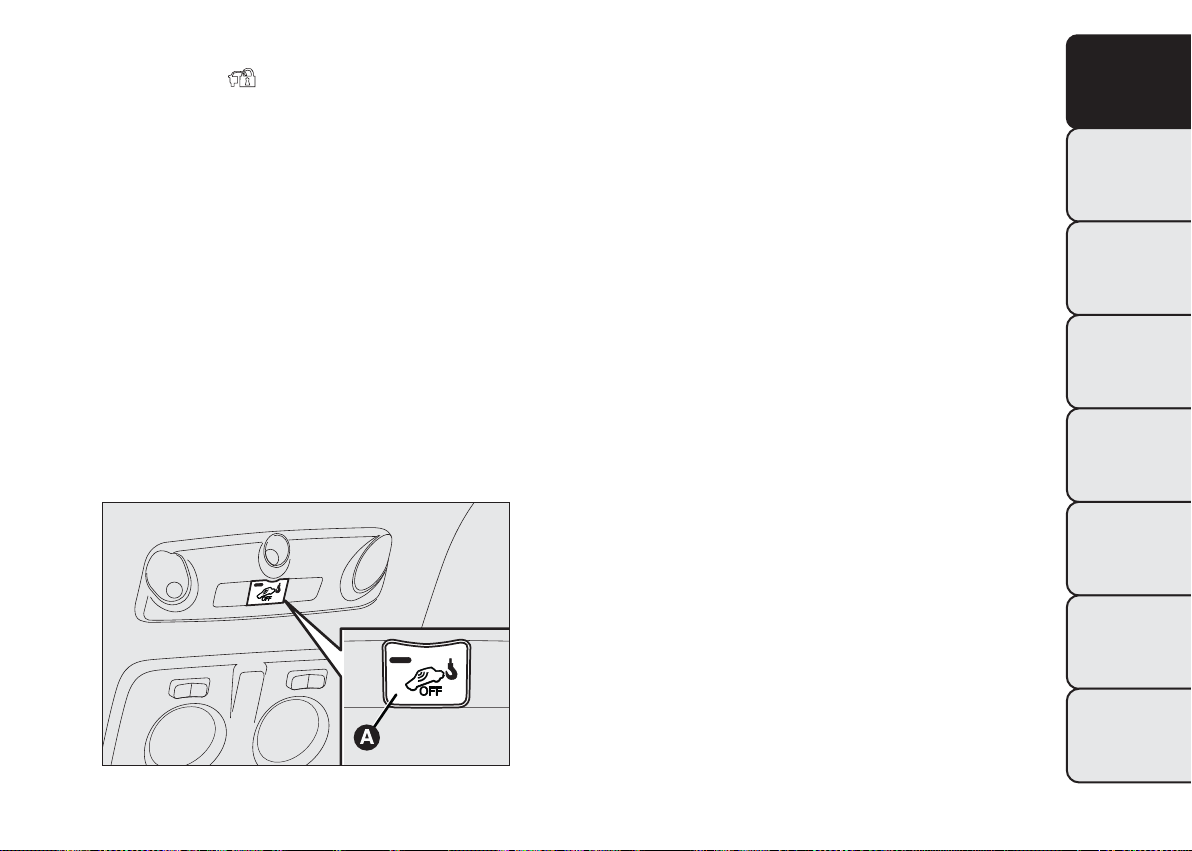
Press the left-hand side of the lens A fig. 40, as
shown in the diagram, to switch the light on/off
when the doors are closed.
KNOW YOUR
VEHICLE
SAFETY
ST
ARTING AND
DRIVING
WARNING LIGHTS
AND MESSAGES
IN AN EMERGENCY
SERVICING AND
MAINTENANCE
fig. 40
TECHNICAL
SPECIFICATIONS
INDEX
F0T0113
49
Page 51

FRONT CEILING LIGHT WITH SPOT
KNOW YOUR
VEHICLE
LIGHTS
(for versions/markets, where provided)
Switch A fig. 41 is used to switch the ceiling lights
on/off.
With switch A in the middle position, lights C and D
SAFETY
go on/off fig. 41when the doors are opened/closed.
With switch A pressed to the left, the lights C and D
ST
ARTING AND
DRIVING
arealwaysoff.
With switch A pressed to the right, the lights C and
D are always on.
The lights are faded out.
WARNING LIGHTS
AND MESSAGES
Switch B fig. 41 is a spot light; when the ceiling light
is off, it switches on individually:
❒ light C if pressed on the left side;
❒ light D if pressed on the right side.
IN AN EMERGENCY
SERVICING AND
MAINTENANCE
IMPORTANT Before getting out of the vehicle, make
sure both switches are in the middle position; when
the doors are closed, the lights switch off to prevent
the battery from being run down. In any case, if
the switch is left in the permanently on position, the
courtesy light goes off automatically 15 minutes
after the engine switching off.
REAR CEILING LIGHT WITH MOVABLE
LENS
(for versions/markets, where provided)
The light comes on automatically when a front door
or sliding side door is opened and goes out when
it is closed.
Press the left-hand side of the lens A fig. 42, as
shown in the diagram, to switch the light on/off
when the doors are closed.
TECHNICAL
SPECIFICATIONS
INDEX
50
fig. 41
F0T0121
fig. 42
F0T0114
Page 52

REAR CEILING LIGHTS WITH REMOVABLE
AUTO
OFF
TORCH
(for versions/markets, where provided)
The light comes on automatically when you open the
sliding side doors (for versions/markets where
provided) and the rear swing doors, and goes out
when you close them.
Press switch A fig. 43 to turn the light on/off with
the doors closed.
Switch A can be set to three different positions:
❒ switch in central position (position 0), light comes
on when a door is opened;
❒ switch pushed up (position 1), light is always on;
❒ switch pushed down (position2-AUTOOFF),
light is always off.
O
UT
A
TORCH FUNCTION
(for versions/markets, where provided)
This is located on the right side of the load
compartment. It is used as both a fixed light and a
portable electric torch.
To use the removable torch A fig. 44, push button B
and remove the torch in the direction shown by
the arrow. Then press switch C to switch the light
on/off.
When the removable light is secured to its fixed
support, the electric torch battery is automatically
recharged.
With the vehicle stationary and the ignition key
either turned to STOP or removed, the courtesy
light is recharged for a maximum of 15 minutes.
O
AUT
KNOW YOUR
VEHICLE
SAFETY
ST
ARTING AND
DRIVING
WARNING LIGHTS
AND MESSAGES
IN AN EMERGENCY
SERVICING AND
MAINTENANCE
TECHNICAL
SPECIFICATIONS
fig. 43
F0T0116
fig. 44
INDEX
F0T0115
51
Page 53

BOOT LIGHT
KNOW YOUR
VEHICLE
(for versions/markets, where provided)
The lamp fig. 45 comes on automatically when the
boot is opened and goes out when it is closed.
SWITCHING CEILING LIGHTS ON/OFF
SAFETY
The ceiling lights switch on/off in the following ways:
Ceiling lights on without locking the doors
ST
ARTING AND
DRIVING
Front ceiling light: comes on when the front doors
are opened.
Rear ceiling light: on manually.
WARNING LIGHTS
AND MESSAGES
Removable ceiling light (alternative to rear ceiling
light): on manually (fixed part).
IN AN EMERGENCY
SERVICING AND
MAINTENANCE
Ceiling lights off when locking the door s
Front and rear ceiling light (also with optional
removable ceiling light): off (faded out) when the
sliding side doors, rear swing doors or front doors
are closed.
With independent load compartment
Front ceiling light: fades out when the front doors
are closed.
Rear ceiling light (also with optional removable
ceiling light): off (faded out) closing the rear doors.
TECHNICAL
SPECIFICATIONS
INDEX
52
fig. 45
F0T0252
Page 54

COMMANDS
HAZARD LIGHTS
They are turned on by pressing switch A fig. 46,
regardless of the position of the ignition key.
Instrument panel warning lights
this device is on. Press switch A again to turn the
lights off.
IMPORTANT The use of hazard warning lights is
governed by the highway code of the country you are
in. Keep to the rules.
and lit up when
Emergency braking
(for versions/markets, where provided)
In the event of emergency braking the hazard lights
come on automatically along with the instrument
panel warning lights
and . The function switches
off automatically when the nature of the braking
changes. This function complies with the relevant
legislations currently in force.
KNOW YOUR
VEHICLE
SAFETY
ST
ARTING AND
DRIVING
WARNING LIGHTS
AND MESSAGES
IN AN EMERGENCY
SERVICING AND
MAINTENANCE
fig. 46
TECHNICAL
SPECIFICATIONS
INDEX
F0T0049
53
Page 55

FOG LIGHTS
KNOW YOUR
VEHICLE
(for versions/markets, where provided)
Press button
turn the fog lights on. Instrument panel warning light
Press the button again to turn the lights off.
SAFETY
REAR FOG LIGHTS
ST
ARTING AND
DRIVING
Press button
front fog lights on to turn the rear fog lights on.
Instrument panel warning light
Press the button again to turn the lights off or turn
WARNING LIGHTS
AND MESSAGES
off the dipped beam headlights and/or the front
fog lights (for versions/markets, where provided).
IN AN EMERGENCY
SERVICING AND
MAINTENANCE
comes on.
fig. 47 with the side/taillights on to
fig. 47 with the dipped beams or
comes on.
INTERIOR FITTINGS
DRIVER'S SEAT ARM REST
(for versions/markets, where provided)
On some versions, the driver side front seat has an
armrest.
Raise or lower the armrest as shown by the arrows
fig. 48.
TECHNICAL
SPECIFICATIONS
INDEX
54
fig. 47
F0T0450
fig. 48
F0T0056
Page 56

GLOVE COMPARTMENT
This is located in front of the passenger seat fig. 49.
ODDMENT TRAY
(for versions/markets, where provided)
Use handle A fig. 50 to open.
fig. 49
F0T0187
WARNING
Never travel with the oddment tray
o
pen: it could injure the passenger in the
event of a crash.
FRONT POWER SOCKET (12V)
This is located on the central unit fig. 51 and only
works with the key at MAR.
Lift cap B fig. 51 to use.
CIGAR LIGHTER
(for versions/markets, where provided)
The cigar lighter is positioned on the central console.
Press the button A fig. 51 to switch on the cigar
lighter with key in the MAR position.
After a few seconds the button snap back to its initial
position and the cigar lighter is ready for use.
KNOW YOUR
VEHICLE
SAFETY
ST
ARTING AND
DRIVING
WARNING LIGHTS
AND MESSAGES
IN AN EMERGENCY
SERVICING AND
MAINTENANCE
fig. 50
F0T0069
fig. 51
TECHNICAL
SPECIFICATIONS
INDEX
F0T0454
55
Page 57

IMPORTANT Always check that the cigar lighter is
KNOW YOUR
switched off.
VEHICLE
SAFETY
children don't touch it: risk of fire and/or
burning.
ST
ARTING AND
DRIVING
ASHTRAY
(for versions/markets, where provided)
WARNING LIGHTS
AND MESSAGES
The ashtray is a removable spring-loaded plastic box
that can be fitted into the cup/can holders on the
central console fig. 52.
IN AN EMERGENCY
SERVICING AND
MAINTENANCE
WARNING
The cigar lighter gets extremely hot.
Han
dle it carefully and make sure
WARNING
Do not use the ashtray as a waste paper
bask
et: it might catch fire in contact
with cigarette stubs.
SUN VISORS
The driver and passenger sun visors fig. 53 can be
moved back and forth and to the side.
There is a space for storing tickets behind the visor
on the driver's side.
A vanity mirror may be fitted to the passenger's sun
visor on some versions.
TECHNICAL
SPECIFICATIONS
INDEX
56
fig. 52
F0T0117
fig. 53
F0T0188
Page 58

HINGED REAR SIDE WINDOWS
(for versions/markets, where provided)
To open, proceed as follows fig. 54 fig. 55:
❒ move the lever A fig. 55 outwards until the
window fully opens.
❒ push the lever back until it locks into place.
fig. 54
F0T0134
To close, carry out the process in reverse until the
lever clicks back into its original place.
KNOW YOUR
VEHICLE
SAFETY
ST
ARTING AND
DRIVING
WARNING LIGHTS
AND MESSAGES
IN AN EMERGENCY
SERVICING AND
MAINTENANCE
fig. 55
TECHNICAL
SPECIFICATIONS
INDEX
F0T0135
57
Page 59

KNOW YOUR
VEHICLE
DOORS
DOOR CENTRAL LOCKING/UNLOCKING
double-flash the direction indicators. Turn the key
anticlockwise in the driver's door to unlock all
the doors.
Locking from the outside
The doors will be locked only if all doors are shut. If
SAFETY
one or more of the doors is open after button
is pressed on the remote control fig. 56,
the direction indicators will flash quickly for around
ST
ARTING AND
DRIVING
three seconds. You can lock all the doors by turning
the key clockwise in the driver's door.
Pressing button
quick succession to activate the dead lock device
WARNING LIGHTS
(see "Dead lock").
AND MESSAGES
Unlocking from the outside
Press button
IN AN EMERGENCY
switch on the ceiling lights temporarily and
SERVICING AND
MAINTENANCE
TECHNICAL
SPECIFICATIONS
on the remote control twice in
briefly to unlock all the doors,
SLIDING SIDE DOORS
(for versions/markets, where provided)
WARNING
Before opening a door, ensure that you
can
do it in safety conditions.
Make sure that the r ight sliding side door
is all closed before refuelling to prevent
damage to the door and to the open fuel
filler cap activated during refuelling operations.
WARNING
The right sliding side door cannot be
o
pened with the fuel flap open during
refuelling.
58
INDEX
fig. 56
F0T0242
Page 60

On Cargo versions, the sliding side door is fitted
with a spring-loaded latch that stops the door from
opening any further. To lock it, simply push the
door as far as it will go; to unlock it, pull forward
firmly.
In any case, make sure that the door is properly
hooked to the system which keeps the door fully
open.
WARNING
Do not leave the sliding side door open
w
hen the vehicle is parked on a
gradient.A knock could release the latch leaving
the door free to move.
Opening/closing from the outside
Opening: turn the key in the lock and pull the handle
fig. 57 in the direction shown by the arrow, then
slide the door towards the rear of the vehicle until it
locks into place and can go no further.
Closing: push the handle A fig. 57 towards the front
of the vehicle. Turn the key with metal insert in
the closing direction.
Opening/closing from the inside
Opening: push switch A fig. 58 to unlock the door,
then pull the lever A fig. 59 and slide the door
towards the rear of the vehicle until it can go no
further.
KNOW YOUR
VEHICLE
SAFETY
ST
ARTING AND
DRIVING
WARNING LIGHTS
AND MESSAGES
Before leaving the vehicle parked with
sli
ding doors open, always check that
the latch is engaged.
WARNING
fig. 57
IN AN EMERGENCY
SERVICING AND
MAINTENANCE
TECHNICAL
SPECIFICATIONS
INDEX
F0T0209
59
Page 61

KNOW YOUR
VEHICLE
SAFETY
ST
ARTING AND
DRIVING
Closing: push switch A fig. 58 to release the door
and then push it towards the front of the vehicle.
CHILD LOCK
This system prevents opening the sliding side doors
from the inside.
The device can be engaged only with the sliding side
door open fig. 60:
❒ position1-device engaged (door locked);
❒ position2-device not engaged (door may be
opened from the inside).
The device remains engaged even if the doors are
unlocked remotely.
WARNING LIGHTS
AND MESSAGES
IN AN EMERGENCY
SERVICING AND
MAINTENANCE
TECHNICAL
SPECIFICATIONS
INDEX
60
fig. 58
fig. 59
F0T0197
F0T0137
WARNING
Always use this device when carrying
children.
2
1
fig. 60
F0T0138
Page 62

WINDOWS
FRONT ELECTRIC WINDOWS
(for versions/markets, where provided)
Buttons fig. 61 are located on the driver's door panel
to control the following functions with the key on:
A: Opening/closing left window
B: Opening/closing right window
Push button A or B to open/close the appropriate
window.
When one of the two buttons is pressed briefly, the
window moves in stages; if the button is held down,
"continuous automatic" operation is activated both
for closing and opening. Press button A or B again to
stop the window in its current position.
The electric windows are fitted with a security
system (for versions/markets, where provided) that
can detect the presence of an obstacle whilst the
window is closing; when this happens, the system
kicks in and the movement of the glass is
immediately reversed.
IMPORTANT The system will automatically enter
“recovery” mode (self-protection) if the anti-crushing
function is activated 5 times in only one minute.
This condition is apparent because the window
closing in stages.
If this occurs, restore the system as follows:
❒ open the windows;
or
❒ turn the key off (STOP position) and then on
(MAR).
If no malfunction is present, the window returns to
its normal operation automatically.
IMPORTANT With the key off or removed, the
windows remain activated for about two minutes and
are deactivated as soon a door is opened.
KNOW YOUR
VEHICLE
SAFETY
ST
ARTING AND
DRIVING
WARNING LIGHTS
AND MESSAGES
IN AN EMERGENCY
SERVICING AND
MAINTENANCE
fig. 61
TECHNICAL
SPECIFICATIONS
INDEX
F0T0044
61
Page 63

KNOW YOUR
VEHICLE
operation, always check that no-one is exposed
to the risk of being injured directly by the
SAFETY
moving window or by objects getting caught and
dragged. When leaving the car, always remove
the ignition key to avoid the risk of injury
due to accidental operation of the electric
ST
ARTING AND
windows.
DRIVING
MANUAL FRONT WINDOWS
WARNING LIGHTS
AND MESSAGES
On some versions, the front windows are opened
and closed manually.
Wind the handle to open/close.
IN AN EMERGENCY
SERVICING AND
MAINTENANCE
WARNING
Improper use of the electric windows
can
be dangerous. Before and during
BOOT
OPENING THETAILGATE FROMTHE
OUTSIDE
The tailgate (when unlocked) can only be opened
from the outside of the car using the electric opening
handle A fig. 62 located under the handle.
The tailgate can be opened at any time if the doors
are unlocked.
To open it, activate the handle by opening one of the
front doors or unlocking the doors with the remote
control or using the mechanic key.
TECHNICAL
SPECIFICATIONS
INDEX
62
fig. 62
F0T0250
Page 64

EMERGENCY OPENING FROM THE INSIDE
In the event of an emergency, you can open the
tailgate from inside as follows:
❒ Open the sliding side door and fully fold the rear
seats;
❒ from inside the boot, press lever A fig. 63 and
open the tailgate.
WARNING
If you are travelling in areas with few
f
illing stations and you want to
transport fuel in a spare tank, comply with the
law by using only an approved, suitably secured
tank. However, the risks in case of collision
increase.
WARNING
Never exceed the maximum allowed
load
in the boot (see "Technical
Specifications" section). Make sure that the
objects are well arranged in the boot so that
they will not be projected forwards following
sudden braking.
DOUBLE REAR SWING DOORS
(for versions/markets, where provided)
The double rear swing doors fig. 64 are fitted with a
spring-loaded system that stops them when they
have opened to an angle of approximately 90
degrees.
KNOW YOUR
VEHICLE
SAFETY
ST
ARTING AND
DRIVING
WARNING LIGHTS
AND MESSAGES
IN AN EMERGENCY
SERVICING AND
MAINTENANCE
fig. 63
F0T0285
fig. 64
TECHNICAL
SPECIFICATIONS
INDEX
F0T0139
63
Page 65

To open them wider to an angle of 180 degrees, push
KNOW YOUR
VEHICLE
the locking device A fig. 65 (one on each side) as
shown in the diagram and simultaneously open the
doors.
SAFETY
strong gust of wind may release the springs,
ST
ARTING AND
forcing the doors to close.
DRIVING
WARNING LIGHTS
AND MESSAGES
IN AN EMERGENCY
SERVICING AND
MAINTENANCE
WARNING
The spring-loaded system is designed for
o
ptimum usage. Accidental knocks or a
Opening/closing the first swing door from the
outside
To open the door, turn the metallic insert of the key
in the lock or press button
on the remote
control and then pull handle A fig. 66 in the direction
of the arrow.
To close the door, turn the key in the lock or press
button
on the remote control.
WARNING
When closing, shut the right-hand door 2
fully
fig. 64 before you close the
left-hand door 1 fig. 64. Never shut the two
doors at the same time.
TECHNICAL
SPECIFICATIONS
INDEX
64
fig. 65
F0T0375
fig. 66
F0T0140
Page 66

Emergency opening of the first swing door
from the inside
From inside, use device A fig. 67.
Opening the second swing door
After having opened the first door, pull handle A fig.
68 in the direction shown by the arrow.
IMPORTANT Pull handle A fig. 68 in the direction of
the arrow only.
REMOVINGTHE PARCEL SHELF
The parcel shelf fig. 69consists of two parts.
To remove it completely, proceed as follows:
❒ open the tailgate and lift the front part A fig. 69 by
releasing the pin A fig. 70 from the seat F fig. 70;
❒ lift the rear part B fig. 69 by releasing the pins B
and C fig. 70 from the seat D and E fig. 70.
KNOW YOUR
VEHICLE
SAFETY
ST
ARTING AND
DRIVING
WARNING LIGHTS
AND MESSAGES
IN AN EMERGENCY
SERVICING AND
MAINTENANCE
fig. 67
F0T0060
fig. 68
TECHNICAL
SPECIFICATIONS
INDEX
F0T0142
65
Page 67

If the seat is completely folded down, remove the
KNOW YOUR
VEHICLE
parcel shelf as described and store it horizontally
between the back of the front seats and the folded
rear seat.
To refit the parcel shelf, follow the same procedure
in reverse.
SAFETY
ST
ARTING AND
DRIVING
WARNING LIGHTS
AND MESSAGES
IN AN EMERGENCY
SERVICING AND
MAINTENANCE
fig. 69
F0T0062
WARNING
You must not use the folded rear seat to
carr
y luggage.The load could be thrown
forward into the back of the front seats,
seriously injuring the occupants.
EXTENDING THE BOOT
Proceed as follows:
❒ open the tailgate and remove the parcel shelf (as
described in the previous paragraph);
❒ completely lower the rear seat headrest;
❒ move the seat belt to the side, making sure that it
is fully extended and not twisted;
TECHNICAL
SPECIFICATIONS
INDEX
66
fig. 70
F0T0456
fig. 71
BA
F0T0444
Page 68

❒ for versions with single rear seat: operate backrest
retainer lever A fig. 71 and fold the backrest
forwards to obtain a flat loading area. When you
lift the lever, you will see a red band B fig. 71.
❒ for versions with split rear seat: lift backrest retainer
lever A fig. 72 and fold the backrest forwards to
obtain a flat loading area. When you lift the lever,
you will see a red band B fig. 72.
Versions with single rear seat
To further expand the load compartment, pull tab A
fig. 73 behind the rear seat backrest and fold seat
and backrest forwards.
fig. 73
A
F0T0416
KNOW YOUR
VEHICLE
SAFETY
ST
ARTING AND
DRIVING
WARNING LIGHTS
AND MESSAGES
IN AN EMERGENCY
SERVICING AND
MAINTENANCE
TECHNICAL
SPECIFICATIONS
fig. 72
F0T0288
fig. 74
INDEX
F0T0445
67
Page 69

To fix the seat, take the red straps A shown in fig. 74
KNOW YOUR
VEHICLE
and fix the ends of the straps in position A and B as
shown in fig. 75
SAFETY
ST
ARTING AND
DRIVING
WARNING LIGHTS
AND MESSAGES
IN AN EMERGENCY
SERVICING AND
MAINTENANCE
Versions with split rear seat
To further expand the load compartment, pull tabs A
and B fig. 76 behind the rear seat backrests and fold
seats and backrests forwards.
fig. 76
F0T0289
TECHNICAL
SPECIFICATIONS
INDEX
68
fig. 75
F0T0446
fig. 77
A
F0T0447
Page 70

To fix the seat, take the red straps A shown in fig. 77
and fix the ends of the straps in position A and B as
shown in fig. 78 for each of the two parts of the seat.
Removing the rear seat
The rear seat can be removed to further expand the
load compartment and carry large loads. After
folding down the rear seat as described previously,
act on the two brackets A fig. 79 positioned under
the side of the seat (one per side).
Repositioning the rear seat
Proceed as follows:
❒ check that the seat belt webbing is correctly
inserted in the corresponding bracket:
❒ take the cushion back to horizontal position and
check that it is secured correctly;
❒ tip back the backrest and check that it is secured
correctly.
An ideogram under the split seat fig. 80 indicates the
method for resecuring the seat to the brackets
screwed to the floor.
KNOW YOUR
VEHICLE
SAFETY
ST
ARTING AND
DRIVING
WARNING LIGHTS
AND MESSAGES
IN AN EMERGENCY
SERVICING AND
MAINTENANCE
fig. 78
F0T0448
fig. 79
TECHNICAL
SPECIFICATIONS
INDEX
F0T0455
69
Page 71

SECURINGYOUR LOAD
KNOW YOUR
VEHICLE
Hooks (various number, according to version) are
fixed to the floor fig. 81 for easy securing load.
SAFETY
ST
ARTING AND
DRIVING
WARNING LIGHTS
AND MESSAGES
IN AN EMERGENCY
SERVICING AND
MAINTENANCE
fig. 80
BONNET
OPENING
Proceed as follows:
❒ pull lever A fig. 82 in the direction indicated by the
arrow;
❒ operate the lever B fig. 83 and lift the bonnet;
❒ lift the bonnet;
❒ lift the engine bonnet supporting lever A fig. 84
and move it until it clicks.
F0T0302
TECHNICAL
SPECIFICATIONS
INDEX
70
fig. 81
F0T0418
fig. 82
F0T0045
Page 72

Before opening the bonnet, check that
win
dscreen wiper arm is not lifted from
the windscreen.
WARNING
CLOSING
Proceed as follows:
❒ lift the bonnet with one hand and pull the device A
fig. 85 towards yourself while you are lowering the
B;
❒ lower the bonnet to approximately 20 centimetres
from the engine compartment and let it drop.
Make sure that the bonnet is completely closed
and not only fastened by the safety catch by trying
to open it. If it is not perfectly closed, do not try
to press the bonnet lid down but open it and
repeat the procedure.
KNOW YOUR
VEHICLE
SAFETY
ST
ARTING AND
DRIVING
fig. 83
fig. 84
F0T0067
F0T0216
IMPORTANT A plate summarising the described
bonnet opening/closing operations is affixed under
the bonnet (see fig. 86).
fig. 85
F0T0283
WARNING LIGHTS
AND MESSAGES
IN AN EMERGENCY
SERVICING AND
MAINTENANCE
TECHNICAL
SPECIFICATIONS
INDEX
71
Page 73

KNOW YOUR
VEHICLE
SAFETY
WARNING
For safety reasons, the bonnet must
al
ways be perfectly closed while
travelling. Make sure that the bonnet is
perfect ly closed and that the lock is engaged. If
you discover during travel that the lock is not
fully engaged, stop immediately and close
the bonnet in the correct manner.
ROOF RACK/SKI RACK
FASTENERS
The fasteners are located at points A, B and C fig.
87.
ROOF RAILS
(for versions/markets, where provided)
ST
ARTING AND
DRIVING
WARNING LIGHTS
AND MESSAGES
IN AN EMERGENCY
SERVICING AND
MAINTENANCE
TECHNICAL
SPECIFICATIONS
INDEX
72
fig. 86
F0T0215
On some versions, the vehicle has two rails fig.
88which, with the addition of special accessories, can
be used to carry various objects (e.g. skis,
surfboards, etc.).
WARNING
Respect the regulations in force
c
oncerning maximum clearance.
fig. 87
F0T0154
Page 74

Distribute the load evenly and be careful
to side winds when driving.
After travelling for a short distance,
ch
eck that the fastening screws are
correctly tightened.
Never exceed the maximum permitted
loads; see chapter "Technical Data".
WARNING
HEADLIGHTS
LIGHT BEAM DIRECTION
The correct direction of the headlights is essential
for the comfort and safety of the driver and other
road users. To ensure the best visibility when
travelling with the headlights on, the headlight
alignment must be correct. Contact a Fiat Dealership
to have the direction checked and, if necessary,
adjusted.
HEADLIGHT ALIGNMENT CORRECTOR
This device works with the ignition key in the MAR
position and the dipped headlights on.
The vehicle tilts backwards when it is laden, raising
the beam.
The beams must therefore be aimed again in this
case.
KNOW YOUR
VEHICLE
SAFETY
ST
ARTING AND
DRIVING
WARNING LIGHTS
AND MESSAGES
IN AN EMERGENCY
SERVICING AND
MAINTENANCE
fig. 88
F0T0435
fig. 89
TECHNICAL
SPECIFICATIONS
INDEX
F0T0451
73
Page 75

Adjusting headlight alignment
KNOW YOUR
VEHICLE
ST
ARTING AND
DRIVING
WARNING LIGHTS
AND MESSAGES
Press
The instrument panel display shows the position in
relation to the adjustment set.
Position 0 - one or two people in the front seats.
SAFETY
Position1-fivepeople.
Position2-fivepeople + load in the boot.
Position 3 - driver + maximum permitted load
stowed in the boot.
IMPORTANT Check the alignment of the light beams
each time the weight of the load transported
changes.
FOG LIGHT DIRECTION
(for versions/markets, where provided)
or on the control panel fig. 89.
ADJUSTING THE HEADLIGHTS WHEN
ABROAD
The dipped headlights are adjusted to work in the
country where the vehicle was originally purchased.
When in countries where you drive on the other
side of the road, you need to alter the beam
direction by affixing a specially designed self-adhesive
film in order not to dazzle the vehicles travelling in
the opposite direction. Such film is provided by
Lineaccessori Fiat and is available at Fiat Dealerships.
IN AN EMERGENCY
SERVICING AND
MAINTENANCE
TECHNICAL
SPECIFICATIONS
Contact a Fiat Dealership to have the direction
checked and, if necessary, adjusted.
INDEX
74
Page 76

ABS SYSTEM
This is an integral part of the braking system, which
prevents one or more wheels from locking or
slipping regardless of the road surface conditions and
braking intensity, giving the best control during
emergency braking.
The EBD system (Electronic Braking Force
Distribution) completes the system, allowing the
brake force to be distributed between the front and
rear wheels.
IMPORTANT For maximum efficiency of the braking
system, a bedding-in period of about 500 km is
needed: during this period it is better to avoid sharp,
repeated and prolonged braking.
WARNING
If the ABS cuts in, it is a sign that the
gr
ip between tyre and the road surface
has reached t he limit: you must slow down to
match the speed to the road grip available.
WARNING
The ABS gets the most from the
av
ailable grip, but it cannot improve it;
you should t herefore take every care when
driving on slippery surfaces and not take
unnecessary risks.
KNOW YOUR
VEHICLE
SAFETY
ST
ARTING AND
DRIVING
WARNING LIGHTS
AND MESSAGES
SYSTEM INTERVENTION
The driver can tell the ABS system has come into
action because the brake pedal pulsates slightly and
the system gets noisier: it means that the vehicle
speed should be altered to suit the type of road
surface.
WARNING
When the ABS cuts in and you feel the
br
ake pedal pulsating, do not remove
your foot, but keep the pedal pushed down; in
doing so you, will stop in the shortest distance
possible under the road conditions at the time.
FAILURE INDICATIONS
ABS failure
ABS failure is indicated by warning light
instrument panel coming on (together with the
appropriate message on the multifunction display on
some versions) (see “Warning lights and messages”).
In this case, the braking system will work as normal,
but without the extra capacity offered by the ABS
system. Drive carefully to the nearest Fiat Dealership
to have the system checked.
in the
IN AN EMERGENCY
SERVICING AND
MAINTENANCE
TECHNICAL
SPECIFICATIONS
INDEX
75
Page 77

EBD failure
KNOW YOUR
VEHICLE
ST
ARTING AND
DRIVING
WARNING LIGHTS
AND MESSAGES
IN AN EMERGENCY
SERVICING AND
MAINTENANCE
ABS failure is indicated by warning light
the instrument panel coming on (together with the
appropriate message on the multifunction display
on some versions) (see “Warning lights and
messages”).
SAFETY
In this case, the rear wheels may suddenly lock and
the vehicle may swerve when braking sharply. Drive
carefully to the nearest Fiat Dealership to have
the system checked.
multifunction display on some versions), stop
the vehicle immediately and contact the nearest
Fiat Dealership. Fluid leaking from the
hydraulic system will compromise the operation
of the braking system, whether it is of the
conventional type or with ABS.
and in
WARNING
If only warning light
instrument panel (with a message in the
lights up in the
BRAKE ASSIST (integrated ESP emergency
braking assistance)
(for versions/markets, where provided)
This system (which is compulsory) recognises
emergency braking according to the speed of
operation of the brake pedal and provides additional
hydraulic braking pressure to support that applied
by the driver. This allows faster and more powerful
operation of the braking system.
The Brake Assist is deactivated on versions equipped
with ESP if there is an ESP system failure (indicated
by the warning light and the message on the
multifunction display, for versions/markets where
provided).
WARNING
When the ABS cuts in and you feel the
br
ake pedal pulsating, do not remove
your foot, but keep the pedal pushed down; in
doing so you, will stop in the shortest distance
possible under the road conditions at the time.
TECHNICAL
SPECIFICATIONS
INDEX
76
Page 78

ESP SYSTEM (Electronic Stability
Program)
(for versions/markets, where provided)
This is an electronic system that controls vehicle
stability in the event of tyre grip loss, helping to
maintain directional control.
The ESP system is therefore particularly useful when
the grip conditions of road surfaces change.
The MSR system (adjustment of the engine braking
torque during gear changes) and the HBA system
(automatic increase in the braking pressure during
emergency braking) are present with ESP, ASR and
Hill Holder systems (for versions/markets where
provided).
SYSTEM INTERVENTION
It is signalled by the blinking of the instrument panel
warning light
is in critical stability and grip conditions.
, to inform the driver that the car
Failure indications
In the event of a failure, the ESP will be automatically
switched off and the
permanently on the instrument panel along with
a message on the multifunction display (for
versions/markets, where provided) (see “Warning
lights and messages” section). The LED on the ASR
OFF button will also light up. Contact a Fiat
Dealership as soon as possible.
Do not take unnecessary risks, even if
y
our vehicle is fitted with an ESP
system.Your driving style should always take
road conditions, visibility and traffic into
account.The driver is always responsible for
road safety.
warning light will come on
WARNING
KNOW YOUR
VEHICLE
SAFETY
ST
ARTING AND
DRIVING
WARNING LIGHTS
AND MESSAGES
IN AN EMERGENCY
Switching the system on
The ESP system is automatically activated when the
vehicle is started and cannot be de-activated.
SERVICING AND
MAINTENANCE
TECHNICAL
SPECIFICATIONS
INDEX
77
Page 79

HILL HOLDER SYSTEM
KNOW YOUR
VEHICLE
ST
ARTING AND
DRIVING
WARNING LIGHTS
AND MESSAGES
IN AN EMERGENCY
SERVICING AND
MAINTENANCE
TECHNICAL
SPECIFICATIONS
(for versions/markets, where provided)
It's integral to the ESP system. It automatically
activates with the following conditions:
❒ uphill: vehicle stationary on a road with a gradient
SAFETY
INDEX
higher than 5%, engine running, brake pedal
pressed and gearbox in neutral or gear other than
reverse;
❒ downhill: vehicle stationary on a road with a
gradient higher than 5%, engine running, brake
pedal pressed and reverse gear engaged.
At pickup the ESP system control unit will keep
brake force on wheels until reaching the torque
suitable for starting, or in any case for max. 2
seconds in order to pass easily from the brake pedal
to the accelerator pedal.
When 2 seconds have elapsed, without any
departure having taken place, the system is
automatically deactivated, gradually releasing the
braking pressure. During this release stage, the
typical brake disengagement noise indicating that the
vehicle is going to move imminently will be heard.
Failure indications
IMPORTANT The Hill Holder system is not a parking
brake; therefore, never leave the vehicle without
having engaged the handbrake, turned the engine off
and engaged the first gear.
WARNING
For the correct operation of the ESP and
A
SR systems, the tyres must be t he
same make and type on all wheels, in perfect
condition and, above all, of the type, make and
size recommended.
ASR SYSTEM (Anti-Slip Regulation)
(for versions/markets, where provided)
This is a traction control system that cuts in
automatically every time one or both drive wheels
slip.
Depending on how slippery the road is, two different
control systems are activated:
❒ if slipping involves both driving wheels, the ASR
function intervenes reducing the power
transmitted by the engine;
❒ if the slipping only involves one of the drive
wheels, it intervenes automatically braking the
wheel that is slipping.
The action of the ASR system is especially useful in
the following conditions:
❒ slipping of the inner wheel round bends due to
dynamic variations in the load of excessive
acceleration;
❒ excessive power transmitted to the wheels, also in
relation to road surface conditions;
78
Page 80

❒ acceleration on slippery, snowy or icy road
surfaces;
❒ in the case of loss of grip on a wet surface
(aquaplaning).
WARNING
For the correct operation of the ESP and
A
SR systems, the tyres must be t he
same make and type on all wheels, in perfect
condition and, above all, of the type, make and
size recommended.
The switching off is shown by the LED in the actual
switch coming on together with a message shown
in the multifunction display (for versions/markets,
where provided).
If the ASR is switched off when driving, it is
automatically switched on again when the vehicle is
started up.
When travelling on snowy roads with snow chains, it
may be helpful to turn the ASR off: in fact, in these
conditions, the driving wheels skidding when moving
off gives you better traction.
KNOW YOUR
VEHICLE
SAFETY
ST
ARTING AND
DRIVING
MSR SYSTEM (engine drive regulation)
This is an integral part of the ASR system that, in the
event of a sudden gear down shift, cuts in and
provides torque to the engine thus preventing
excessive drive wheel drive which, especially in poor
grip conditions, can lead to a loss of stability.
Engagement/ disengagement of the ASR
system
The ASR system switches on automatically each time
the engine is started.
When travelling, the ASR can be switched off and on
again pressing button A fig. 90located among the
controls in the dashboard.
WARNING
Do not take unnecessary risks, even if
y
our vehicle is fitted with this system.
Your driving style must always be suited to the
road conditions, visibility and traffic.
The driver is always responsible for road safety.
fig. 90
F0T0317
WARNING LIGHTS
AND MESSAGES
IN AN EMERGENCY
SERVICING AND
MAINTENANCE
TECHNICAL
SPECIFICATIONS
INDEX
79
Page 81

For the correct operation of the ASR system, the
KNOW YOUR
VEHICLE
ST
ARTING AND
DRIVING
WARNING LIGHTS
AND MESSAGES
IN AN EMERGENCY
SERVICING AND
MAINTENANCE
tyres must absolutely be the same make and type on
all wheels, in perfect condition and, above all, of
the type, make and size specified.
FAILURE INDICATIONS
SAFETY
In the event of a failure, the ASR system will be
automatically switched off and warning light
appear permanently on the instrument panel along
with a message on the multifunction display (for
versions/markets where provided) (see “Warning
lights and messages”). In this case, contact a Fiat
Dealership as soon as possible.
will
TRACTION PLUS SYSTEM
(for versions/markets, where provided)
Traction Plus is a help with driving and setting off in
poor grip conditions (snow, ice, mud, etc.) which
allows the drive force to be evenly distributed over
the same axle when both wheels are slipping.
In effect, Traction Plus acts by braking the wheels
with poor grip (or those slipping more than the
others), thereby transferring the drive force to those
which have more grip on the ground.
This function can be turned on manually by pressing
the T+ button fig. 91 on the dashboard and works
below a level of 30 km/h. Over this speed, it is
automatically deactivated (the LED on the button is
still on) and it is reactivated again when the speed
is below 30 km/h.
TECHNICAL
SPECIFICATIONS
INDEX
80
Page 82

Traction Plus operation
The system is deactivated when starting up. To
activate the "Traction Plus" system, press the button
(T+ fig. 91): the LED on the button switches on.
The activation of the Traction Plus system involves
the following functions being switched on:
❒ inhibition of the ASR function, in order to fully
exploit the engine torque;
❒ the differential locking effect on the front axle,
through the braking system, to improve traction
on irregular grounds.
If the "Traction Plus" system is faulty, the "general
failure" instrument panel warning light
comes on
steady.
EOBD SYSTEM
The EOBD system (European On Board Diagnosis)
allows continuous diagnosis of emission-related
components on the vehicle. It also alerts the driver,
by turning on instrument panel warning light
(together with the relevant message in the
display, on some versions), when these components
are no longer in peak condition (see “Warning
lights and messages” section).
The aim of the system is to:
❒ monitor system efficiency;
❒ warn about increased emissions due to a vehicle
malfunction;
❒ to warn of the need to replace deteriorated
components.
The system also has a connector that can be
interfaced with appropriate equipment, which makes
it possible to read the error codes stored in the
control unit, together with a series of specific
parameters for engine operation and diagnosis.
This check can also be carried out by traffic police.
IMPORTANT After resolving the problem, to check
the system completely, Fiat Dealerships are obliged
to run a bench test and, if necessary, road tests
which may call for a long journey.
KNOW YOUR
VEHICLE
SAFETY
ST
ARTING AND
DRIVING
WARNING LIGHTS
AND MESSAGES
IN AN EMERGENCY
SERVICING AND
MAINTENANCE
TECHNICAL
SPECIFICATIONS
fig. 91
INDEX
F0T0311
81
Page 83

KNOW YOUR
VEHICLE
not light up when the key is turned to MAR to if
while travelling the warning lights comes on
SAFETY
either steady or blinking (along with a message
on the display).The operation of warning light
specific devices. Follow the laws in force in
ST
ARTING AND
the country where you are driving.
DRIVING
WARNING LIGHTS
AND MESSAGES
IN AN EMERGENCY
SERVICING AND
MAINTENANCE
WARNING
Go to a Fiat Dealership as soon as
possible
if warning light
either does
may be checked by the traffic police using
PARKING SENSORS
(for versions/markets, where provided)
These are located in the rear bumper fig. 92 and
their function is to inform the driver, through an
intermittent beeping noise, about the presence of
obstacles behind the vehicle.
ACTIVATION
The sensors are automatically activated when reverse
gear is selected.
The buzzer becomes more frequent as the obstacle
behind the vehicle gets closer to the bumper.
TECHNICAL
SPECIFICATIONS
INDEX
82
fig. 92
F0T0211
Page 84

WARNING BUZZER
Activating the reverse gear, an intermittent buzzer
automatically turns on (a short beep to indicate the
activation of the system).
The beeps:
❒ increase as the distance between the vehicle and
the obstacle decreases;
❒ become continuous when the distance between
the vehicle and the obstacle is less than 30 cm
and stop immediately if the distance increases;
❒ remains constant if the distance between the
vehicle and the obstacle remains unchanged.
Detection distances
Centre operating range 120 cm
Side operating radius 60 cm
If several obstacles are detected by the sensors, only
the nearest one is considered.
FAILURE INDICATIONS
Parking sensor failures are indicated, when engaging
reverse gear, by a three-second beep.
The sensor must be free of mud, dirt, snow
or ice in order for the system to work. Be
careful not to scratch or damage the
sensors while cleaning them.Avoid using dry,
rough or hard cloths.The sensors should be
washed using clean water with the addition of car
shampoo if necessary.When using special
washing equipment such as high pressure jets or
steam cleaning, clean the sensors very quickly
keeping the jet more than 10 cm away.
OPERATION WITHTRAILER
The operation of the sensors is automatically
deactivated when the plug for the electric cable for
the trailer is inserted in the vehicle tow hook socket.
The sensors are automatically enabled again when
the trailer cable plug is removed.
GENERAL WARNINGS
❒ During parking manoeuvres, pay the utmost
attention to any obstacles that could be located
above or below the sensors.
❒ Sometimes, objects located very near the rear of
the vehicle are not detected and could therefore
damage the vehicle or be damaged themselves.
KNOW YOUR
VEHICLE
SAFETY
ST
ARTING AND
DRIVING
WARNING LIGHTS
AND MESSAGES
IN AN EMERGENCY
SERVICING AND
MAINTENANCE
TECHNICAL
SPECIFICATIONS
INDEX
83
Page 85

❒ The signals sent out by the sensors can be altered
KNOW YOUR
VEHICLE
SAFETY
ST
ARTING AND
DRIVING
WARNING LIGHTS
AND MESSAGES
IN AN EMERGENCY
SERVICING AND
MAINTENANCE
by dirt, snow or ice deposited on the sensors or
by ultrasound systems (e.g. truck pneumatic brakes
or pneumatic drills) near the vehicle.
❒ The parking sensors work properly with the swing
doors closed. If they are open, they can cause the
system to send false signals: always close the
rear doors.
dangerous manoeuvres still rests with the
driver.When parking, make sure that no-one is
standing in the area, especially children or
animals. Parking sensors are designed to assist
drivers; however, you must always concentrate
fully during potent ially dangerous manoeuvres,
even if carried out at low speeds.
WARNING
The ultimate responsibility when
par
king and carrying out other
RADIO
(for versions/markets, where provided)
Read the Supplement attached to this Owner's
Handbook for the operation of the radio with
CD/MP3 player (for versions/markets, where
provided).
LIGHT SETUP
The system consists of:
❒ radio power wires
❒ front speaker wires (located in wing mirror panels)
❒ speaker wires in front door panels
❒ rear speaker wires (located next to parcel shelf)
(for versions/markets, where provided)
❒ radio housing
❒ antenna wires.
TECHNICAL
SPECIFICATIONS
INDEX
84
Page 86

FULL SETUP
The system consists of:
❒ radio power wires
❒ front speaker wires (located in wing mirror panels)
❒ speaker wires in front door panels
❒ rear speaker wires (located next to parcel shelf)
(for versions/markets, where provided)
❒ two tweeters in the wing mirror panels
❒ two midwoofers in the lower part of the front
doors
❒ two rear speaker (located next to parcel shelf)
(for versions/markets, where provided)
❒ radio housing
❒ antenna wires
❒ antenna.
RADIO INSTALLATION
The radio must be installed in the place occupied by
the central storage compartment, where you will find
the wiring.
Press tabs A fig. 93 to remove the compartment.
WARNING
To connect to the existing wiring in the
v
ehicle, contact a Fiat Dealership to
prevent any problems that could impair vehicle
safety.
KNOW YOUR
VEHICLE
SAFETY
ST
ARTING AND
DRIVING
WARNING LIGHTS
AND MESSAGES
IN AN EMERGENCY
SERVICING AND
MAINTENANCE
fig. 93
TECHNICAL
SPECIFICATIONS
INDEX
F0T0032
85
Page 87

INSTALLING ELECTRICAL/
KNOW YOUR
VEHICLE
ST
ARTING AND
DRIVING
WARNING LIGHTS
AND MESSAGES
IN AN EMERGENCY
SERVICING AND
MAINTENANCE
ELECTRONIC DEVICES
Electrical and electronic devices installed after buying
the vehicle must carry the following label:
FGA S.p.A. authorises the installation of transceiving
SAFETY
devices provided that they are installed by a
specialised centre according to rules of good
engineering practice and in compliance with the
manufacturer's instructions.
IMPORTANT Traffic authorities may not allow the
vehicle on the road if devices are fitted that involve
modifications to the features of the vehicle. This may
also cause lapse of the warranty in relation to faults
caused by the change or either directly or indirectly
related to it.
FGA S.p.A. shall not be liable for damage caused by
the installation of accessories either not supplied
or recommended by FGA S.p.A. and/or not installed
in compliance with the provided instructions.
RADIO TRANSMITTERS AND CELLULAR
PHONES
Transceiver apparatus (e.g. mobile phones, CB radios
etc.) should not be used inside the vehicle unless a
separate antenna is mounted on the roof.
IMPORTANT The use of such devices inside the
passenger compartment (without an external
antenna) may, in addition to potential damage to the
health of the passengers, cause malfunctions in the
vehicle electronic systems, compromising the safety
of the vehicle.
In addition, the transmission and reception of these
devices may be affected by the shielding effect of
the vehicle body.
With regard to EC-approved mobile phones (GSM,
GPRS, UMTS), you should adhere strictly to the
instructions provided by the mobile phone
manufacturer.
TECHNICAL
SPECIFICATIONS
INDEX
86
fig. 94
DISPOSITIVI-ELETTRONICI
Page 88

REFUELLING THE VEHICLE
DIESEL ENGINES
Operation at low temperatures
If the outside temperature is very low, the diesel
thickens due to the formation of paraffin clots with
consequent defective operation of the fuel supply
system.
In order to avoid these problems, different types of
diesel are distributed according to the season:
summer type, winter type and arctic type
(cold/mountain areas). If refuelling with diesel fuel
whose specifications are not suitable for the usage
temperature, it is advisable to mix TUTELA DIESEL
ART additive in the proportions shown on the
container with the fuel. Pour the additive into the
tank before the fuel.
When using or parking the vehicle for a long time in
the mountains or cold areas, it is advisable to refuel
using locally available diesel.
In this case, it is also advisable to keep the tank over
50% full.
For diesel engines, use only diesel fuel for
motor vehicles in accordance with EN590
European specifications.The use of other
products or mixtures may damage the engine
beyond repair and consequently invalidate the
warranty, depending on the damage caused.
If you accidentally introduce other types of fuel
into the tank, do not start the engine. Empty the
tank. If the engine has run also for a very short
time, you will need to have the entire fuel feed
system emptied in addition to the tank.
REFUELLING CAPACITY
To fill the tank completely, top up twice after the
first click of the trigger. Further top-ups could cause
faults in the fuel feeding system.
KNOW YOUR
VEHICLE
SAFETY
ST
ARTING AND
DRIVING
WARNING LIGHTS
AND MESSAGES
IN AN EMERGENCY
SERVICING AND
MAINTENANCE
TECHNICAL
SPECIFICATIONS
INDEX
87
Page 89

FUEL FILLER CAP
KNOW YOUR
VEHICLE
Opening
1) Open the flap A fig. 95 by pulling it outwards,
keep the cap B fig. 95 still, insert the ignition key in
the lock and turn it anticlockwise.
SAFETY
2) Turn the cap anticlockwise and remove it.
The cap has a device C fig. 95 that attaches it to the
flap so it cannot be lost. When refilling, attach the
ST
ARTING AND
DRIVING
cap to the flap, as illustrated.
Closing
1) Fit the cap (complete with key) and turn it
WARNING LIGHTS
AND MESSAGES
clockwise until it clicks once or more.
2) Turn the key clockwise and extract it, then close
the flap.
IN AN EMERGENCY
SERVICING AND
MAINTENANCE
The hermetic seal may cause a slight increase in
pressure in the tank. A suction noise when you
release the cap is therefore entirely normal.
Do not place naked flames or lit
cigarettes near to the fuel filler: fire risk.
Keep your face away from the fuel filler
to prevent breathing in harmful vapours.
TECHNICAL
SPECIFICATIONS
INDEX
88
fig. 95
F0T0068
Page 90

FUEL CUT-OFF SYSTEM
This system is triggered after a collision as follows by:
❒ cutting off fuel supply and consequently stopping
the engine
❒ automatically unlocking the doors
❒ turning on the lights inside the vehicle.
When the system has been triggered, the message
“Fuel cut off, see handbook” is displayed on some
versions.
Check carefully for fuel leaks, for instance in the
engine compartment, under the vehicle or near the
tank area.
After a crash, turn the ignition key to STOP to avoid
draining the battery.
The following procedure should be carried out to
restore the correct operation of the vehicle:
❒ turn the ignition key to the ON position;
❒ turn on the right direction indicator;
❒ turn off the right direction indicator;
❒ turn on the left direction indicator;
❒ turn off the left direction indicator;
❒ turn on the right direction indicator;
❒ turn off the right direction indicator;
❒ turn on the left direction indicator;
❒ turn off the left direction indicator;
❒ turn the ignition key to the OFF position.
WARNING
If, after a crash, you smell fuel or notice
leaks
from the fuel system, do not rearm
the system to avoid the risk of fire.
KNOW YOUR
VEHICLE
SAFETY
ST
ARTING AND
DRIVING
WARNING LIGHTS
AND MESSAGES
IN AN EMERGENCY
SERVICING AND
MAINTENANCE
TECHNICAL
SPECIFICATIONS
INDEX
89
Page 91

PROTECTING THE ENVIRONMENT
KNOW YOUR
VEHICLE
ST
ARTING AND
DRIVING
WARNING LIGHTS
AND MESSAGES
IN AN EMERGENCY
SERVICING AND
MAINTENANCE
TECHNICAL
SPECIFICATIONS
The following devices are used for reducing diesel
fuel engine emissions:
❒ oxidising catalytic converter
❒ exhaust gas recirculation system (EGR)
SAFETY
❒ diesel particulate filter (DPF) (for versions/
markets, where provided).
DIESEL PARTICULATE FILTER (DPF)
(for versions/markets, where provided)
The Diesel Particulate Filter is a mechanical filter,
integral to the exhaust system, that physically traps
carbon particulates present in the exhaust gases
of diesel engines.
It is needed to eliminate almost all particulates in
compliance with current/future legislation. During
normal use of the vehicle, the engine control unit
records a set of data (e.g.: travel time, type of route,
temperatures, etc.) and it will then calculate how
much particulate has been trapped by the filter.
Since this filter physically traps particulate, it should
be regenerated (cleaned) at regular intervals by
burning the carbon particles. The regeneration
procedure is controlled automatically by the engine
management control unit according to the filter
conditions and vehicle use conditions.
During regeneration, the following may occur: a
limited increase in the engine speed, activation of the
fan, a limited increase in fumes and high
temperatures at the exhaust.
These are not faults; they do not impair vehicle
performance or damage the environment. If
the dedicated message is displayed, refer to the
“Warning lights and messages” section.
90
INDEX
Page 92

SAFETY
SEAT BELTS
USING THE SEAT BELTS
Wear the belt keeping the torso upright and rested
against the backrest.
To fasten the seat belts, hold the tongue A fig. 96and
insert it into the buckle B, until the locking click is
heard.
If the seat belt jams, let it rewind for a short stretch,
then pull it out again without jerking.
To unfasten the seat belts, press button C. Guide the
seat belt with your hand while it is rewinding, to
prevent it from twisting.
WARNING
Never press button C fig. 96 when
t
ravelling.
Through the reel, the belt automatically adapts to
the body of the passenger wearing it, allowing
freedom of movement.
The reel may lock up when the vehicle is parked on a
steep slope: this is perfectly normal. Furthermore,
the reel mechanism locks the belt if it is pulled
sharply or in the event of sudden braking, collisions
and high-speed bends.
All rear seats are fitted with inertia seat belts with
three anchor points and a reel.
KNOW YOUR
VEHICLE
SAFETY
STARTING AND
DRIVING
W
ARNING LIGHTS
AND MESSAGES
IN AN EMERGENCY
fig. 96
F0T0147
WARNING
Remember that, in the event of a violent
c
ollision, back seat passengers not
wearing seat belts represent a serious danger
for the front seat passengers as well as for
themselves.
SERVICING AND
MAINTENANCE
TECHNICAL
SPECIFICATIONS
INDEX
91
Page 93

The rear seat belts must be used as shown in the
KNOW YOUR
VEHICLE
diagram in fig. 97 or fig. 98.
IMPORTANT The red band B on the levers A used
for folding the seat will not appear when the
backrest is correct secured. This red band indicates
SAFETY
that the backrest is not secured.
STARTING AND
DRIVING
W
ARNING LIGHTS
AND MESSAGES
IN AN EMERGENCY
SERVICING AND
MAINTENANCE
fig. 97
F0T0193
IMPORTANT When putting the seats back to their
normal position, make sure the seat belts are
positioned so they are ready to use.
WARNING
Make sure the backrest is properly
sec
ured at both sides (red bands B not
visible) to prevent it moving forward in the
event of sharp braking, causing injuries to
passengers.
TECHNICAL
SPECIFICATIONS
INDEX
92
fig. 98 - N1 versions (4 seats)
F0T0342
Page 94

SBR SYSTEM
The vehicle is equipped with the SBR (Seat Belt
Reminder) system, which warns the driver and the
front passenger if their seat belt is not fastened,
as follows:
❒ warning light
continuously for the first 6 seconds;
❒ warning light
of the beeper for the next 90 seconds.
For permanent deactivation, contact a Fiat
Dealership.
The SBR system can also be reactivated through the
setup menu.
comes on and the buzzer sounds
blinks and intermittent activation
PRETENSIONERS
To increase the protective efficiency of the front seat
belts, the vehicle is fitted with pretensioners. These
devices, in the event of a violent head-on crash or
side impact, rewind the seat belts a few centimetres.
In this way, they ensure that the belts fit tightly to
the wearer before the restraining action begins.
The seat belt reel locks to indicate that the
pretensioner has cut in; the seat belt cannot be
drawn back up even when guided manually.
IMPORTANT To obtain the highest degree of
protection from the action of the pretensioners,
wear the seat so it fits snugly over the chest and
hips.
A small amount of smoke may be produced when the
pretensioners cut in. This smoke is not toxic and
does not indicate a fire.
The pretensioner does not require any maintenance
or lubrication. Anything that modifies its original
conditions invalidates its efficiency. If, due to unusual
natural events (floods, sea storms, etc.), the device
has been affected by water and mud, it absolutely
must be replaced.
KNOW YOUR
VEHICLE
SAFETY
STARTING AND
DRIVING
W
ARNING LIGHTS
AND MESSAGES
IN AN EMERGENCY
SERVICING AND
MAINTENANCE
TECHNICAL
SPECIFICATIONS
INDEX
93
Page 95

KNOW YOUR
VEHICLE
replaced after it has been deployed. Consult the
card in the glove box to check the status of
SAFETY
the pretensioners. Go to a Fiat Dealership to
have the device replaced when the expiration
date approaches.
STARTING AND
DRIVING
W
ARNING LIGHTS
AND MESSAGES
around the pretensioners may cause damage or
trigger them.These devices are not affected by
vibrations caused by irregularities of the road
IN AN EMERGENCY
surface or low obstacles such as kerbs, etc.
Contact a Fiat Dealership for any assistance.
LOAD LIMITERS
SERVICING AND
MAINTENANCE
(for versions/markets, where provided)
To increase passenger safety, the front and rear (for
versions/markets where provided) seat belt reels
contain a load limiter which controls the force acting
TECHNICAL
SPECIFICATIONS
on the chest and shoulders during the belt
restraining action in the event of a head-on collision.
WARNING
The pretensioner can be used only once.
G
o to a Fiat Dealership to have it
Operations which lead to knocks,
vibrations or localised heating (over 100°C
for a maximum of 6 hours) in the area
GENERAL INSTRUCTIONS FOR USING
THE SEAT BELTS
The driver is responsible for respecting (and ensuring
that all the other passengers also respect) the local
laws in force regarding the use of seat belts. Always
fasten the seat belts before setting off.
Seat belts must also be worn by expectant mothers:
the risk of injury in the event of an accident is greatly
reduced for them and the unborn child if they are
wearing a seat belt. Pregnant women must position
the lower part of the belt very low down so that
it passes over the hips and under the abdomen (see
fig. 99).
IMPORTANT The belt must not be twisted. The
upper part must cross the shoulder and the chest
diagonally. The lower part must fit over the hips (as
shown in fig. 100) rather than the abdomen of the
passenger. Do not use devices (clips, etc.) to hold the
seat belt away from your body.
94
INDEX
fig. 99
F0T0003
Page 96

WARNING
For maximum safety, keep the back of
y
our seat upright, lean back into it
and make sure the seat belt fits closely across
your chest and hips. Always fasten the seat belts
on both the front and the rear seats! Travelling
without seat belts will increase the risk of
severe injury and even death in the event of an
accident.
WARNING
Never disassemble or tamper with the
seat
belt or pretensioner components.All
operations must be performed by qualified and
authorised personnel.Always go to a Fiat
Dealership.
IMPORTANT Each seat belt must be used by only
one person. Never travel with a child sitting on the
passenger's lap and a single belt to protect them
both fig. 101. In general, do not place any objects
between the person and the belt.
WARNING
If the belt has been subjected to heavy
s
tress, for example after an accident,
it should be changed completely together with
the anchors, anchor fastening screws and the
pretensioner. In fact, even if the belt has no
visible defects, it could have lost it s resilience.
KNOW YOUR
VEHICLE
SAFETY
STARTING AND
DRIVING
W
ARNING LIGHTS
AND MESSAGES
IN AN EMERGENCY
SERVICING AND
MAINTENANCE
fig. 100
F0T0004
fig. 101
TECHNICAL
SPECIFICATIONS
INDEX
F0T0005
95
Page 97

SEAT BELTS MAINTENANCE
KNOW YOUR
VEHICLE
Observe the following precautions for correct seat
belt maintenance:
❒ always use the belt with the tap taut and never
twisted; make sure that it is free to run without
SAFETY
impediments;
❒ replace the belt after an accident of a certain
severity even if it does not appear damaged.
STARTING AND
DRIVING
Always replace the seat belt if the pretensioners
were deployed;
❒ to clean the belt, wash by hand with water and
mild soap, rinse and leave to dry in the shade.
W
ARNING LIGHTS
AND MESSAGES
Do not use strong detergents, bleach, paints or
any other chemicals which could damage the belt
fibres;
❒ prevent the reels from getting wet: their correct
operation is guaranteed only if water does not
IN AN EMERGENCY
get inside;
❒ replace the seat belt if it shows significant signs of
wear and tear.
SERVICING AND
MAINTENANCE
TECHNICAL
SPECIFICATIONS
INDEX
CARRYING CHILDREN SAFELY
For optimum protection in the event of a crash, all
passengers must be seated and wearing adequate
restraint systems.
This is even more important for children.
This prescription is compulsory in all EC countries
according to EC Directive 2003/20/EC.
Compared with an adult, a child's head is larger and
heavier in proportion to his/her body and the child's
muscular and bone structures are not fully
developed. For this reason, they require restraint
systems which are different from those used by
adults to protect them in the event of an accident.
The research results in relation to the best
protection for children is illustrated in European
Regulation ECE-R44 which divides the restraint
systems into five groups in addition to making their
use compulsory:
Group Weight range
Group0 upto10kg
Group 0+ up to 13 kg
Group 1 9-18 kg
Group 2 15-25 kg
Group 3 22-36 kg
As you can see, the groups overlap partly and, in fact,
there are devices on sale that cover more than one
weight group.
96
Page 98

All restraint devices must bear the type-approval
data along with the control mark on a label firmly
secured to the child seat which must never be
removed.
Over 1.50 m in height, from the point of view of
restraint systems, children are considered as adults
and wear seat belts normally.
Lineaccessori Fiat has child seats for each weight
group. These devices are recommended, having been
specifically designed for Fiat cars.
WARNING
DANGER: Do not put cradle seat s facing
backw
passenger air bag is enabled.
Deployment of t he air bag in an
accident could cause fatal injuries to the child.
It is advisable to carry children on the rear seat,
which is the most protected position in the
event of an accident. Child seats must not be
fitted on the front seat of vehicles with a
passenger air bag; their deployment in
an accident, however serious, could cause fatal
injuries to the child. If necessary, children can
travel in the front seat, if the front passenger air
bag can be disabled. In this case, check that
the air bag is actually deactivated by making
sure the “ warning light appears on the
instrument panel (see “Front passenger air bag”
in the “Front air bags” section). Also, the
passenger seat should be as far back as possible
to avoid contact between the child seat and
the dashboard.
ards on the front seat if the front
KNOW YOUR
VEHICLE
SAFETY
STARTING AND
DRIVING
W
ARNING LIGHTS
AND MESSAGES
IN AN EMERGENCY
SERVICING AND
MAINTENANCE
TECHNICAL
SPECIFICATIONS
INDEX
97
Page 99

GROUPS 0 and 0+
KNOW YOUR
VEHICLE
Babies up to 13 kg must be carried facing backwards
on a cradle seat, which, by supporting the head,
does not induce stress on the neck in the event of
sharp deceleration.
SAFETY
The cradle is restrained by the vehicle seat belts, as
shown in fig. 102 and, in turn, it must restrain the
child with its own belts.
STARTING AND
DRIVING
GROUP 1
Children from 9 kg to 18 kg in weight can be carried
facing forwards if the child seat is fitted with a front
W
ARNING LIGHTS
AND MESSAGES
cushion, through which the car seat belt restrains
both child and seat fig. 103.
IN AN EMERGENCY
SERVICING AND
MAINTENANCE
WARNING
The diagrams are indicative and
pro
vided for assembly purposes only. For
assembly, refer to the instructions supplied with
the child seat by low.
WARNING
Some child restraint systems for weight
groups
0 and 1 have a rear attachment
to the car seat belts and their own seat belts for
securing the child. Due to their weight, they
may be dangerous if incorrectly mounted (e.g.
if fastened to the vehicle seat belts placing a
cushion in between). Follow the assembly
instructions carefully.
TECHNICAL
SPECIFICATIONS
INDEX
98
fig. 102
F0T0006
fig. 103
F0T0007
Page 100

GROUP 2
Children from 15 to 25 kg can be secured using the
car seat belts directly fig. 104.
The child seat is needed only to position the child
correctly with respect to the belts so that the
diagonal section crosses the child's chest and never
the neck, and the lower part is snug on the hips
not the abdomen.
GROUP 3
For children from 22 kg to 36 kg, the size of the
child's chest no longer requires a support to distance
the child's back from the back of the seat.
The figure fig. 105 shows proper child seat
positioning on the rear seat.
Children over 1.50 m in height can wear seat belts
like adults.
KNOW YOUR
VEHICLE
SAFETY
WARNING
The diagrams are indicative and
pro
vided for assembly purposes only. For
assembly, refer to the instructions supplied with
the child seat by law.
fig. 104
F0T0008
WARNING
The diagrams are indicative and
pro
vided for assembly purposes only. For
assembly, refer to the instructions supplied with
the child seat by law.
fig. 105
F0T0009
STARTING AND
DRIVING
W
ARNING LIGHTS
AND MESSAGES
IN AN EMERGENCY
SERVICING AND
MAINTENANCE
TECHNICAL
SPECIFICATIONS
INDEX
99
 Loading...