

Page 1

Page 2
Dear Customer,
Thank you for choosing Fiat and congratulations on your choice of a Fiat Fiorino QUBO.
We have prepared this booklet to enable you to know each detail of your Fiat Fiorino QUBO and use it correctly. Please, read it
carefully before driving your vehicle for the first time. You will find information, tips and important warnings regarding the driving
of your vehicle to help you derive the maximum from the technological features of your Fiat Fiorino QUBO.
You are recommended to carefully read the warnings and indications, marked with the respective symbols:
personal safety;
vehicle integrity;
environmental protection.
The enclosed Warranty Booklet lists the services that Fiat offers to its Customers:
❒
the Warranty Certificate with terms and conditions for maintaining its validity
❒
the range of additional services available to Fiat Customers.
Best regards and happy motoring!
This Owner Handbook describes all the versions of the Fiat Fiorino QUBO.
As a consequence, you should only consider the information which is related to the engine
and bodywork version of the vehicle you have purchased.
Page 3
MUST BE READ!
REFUELLING
Petrol engines: only refuel with unleaded petrol with octane rating (RON) not less than 95 conforming to the
European specification EN 228.
K
ENGINE STARTING
PARKING ON FLAMMABLE MATERIAL
Diesel engines: only refuel with diesel fuel conforming to the European specification EN590. The use of other prod-
ucts or mixtures may damage the engine beyond repair and consequently cause lapse of warranty in relation to the
damage caused.
Petrol engines: make sure that the handbrake is engaged; set the gearshift lever to neutral; fully depress the clutch
without pressing the accelerator, then turn the ignition key to AVV and release it as soon as the engine has started.
Diesel engines: Turn the ignition key to MAR and wait for the warning light m to go out. Turn the ignition key
to AVV and release as soon as the engine starts.
The catalytic converter develops high temperature during operation. Do not park on grass, dry leaves, pine needles
or other flammable material: fire risk.
RESPECTING THE ENVIRONMENT
The vehicle is fitted with a system that allows continuous diagnosis of the components correlated with emissions to
ensure better respect for the environment.
Page 4

ELECTRICAL ACCESSORIES
If, after buying the vehicle, you decide to add electrical accessories (with the risk of gradually draining the battery),
visit a Fiat Dealership. They can calculate the overall electrical requirement and check that the vehicle electric system can support the required load.
SCHEDULED SERVICING
Correct vehicle servicing is essential for ensuring it stays in tip-top condition and safeguards its safety features, its
environmental friendliness and low running costs for a long time to come.
쇵
THE OWNER’S MANUAL CONTAINS…
... important information, advise and warnings for correct use, driving safety and maintenance of your vehicle over
time. Pay special attention to the symbols
ty).
"
(personal safety) #(environmental protection) (vehicle integri-
Page 5

DDAASSHHBBOOAARRDDAANNDDCCOONNTTRROOLLS
S
DASHBOARD
AND CONTROLS
SAFETY
STARTING
AND DRIVING
WARNING
MESSAGES
LIGHTS AND
IN AN
EMERGENCY
AND CARE
MAINTENANCE
TECHNICAL
SPECIFICATIONS
DASHBOARD........................................................................ 5
INSTRUMENT PANEL......................................................... 6
SYMBOLS ............................................................................... 7
THE FIAT CODE SYSTEM ................................................. 7
THE KEYS .............................................................................. 8
ALARM ................................................................................... 11
IGNITION DEVICE ............................................................. 13
INSTRUMENTS .................................................................... 14
DIGITAL DISPLAY ............................................................... 16
MULTIFUNCTIONAL DISPLAY ...................................... 21
TRIP COMPUTER ................................................................ 30
SEATS ...................................................................................... 33
HEAD RESTRAINTS............................................................. 36
STEERING WHEEL .............................................................. 37
REARVIEW MIRRORS ......................................................... 37
HEATING AND CLIMATE CONTROL SYSTEM ........ 39
HEATING AND VENTILATION ...................................... 41
WINDOW WASHING ....................................................... 49
CEILING LIGHTS .................................................................. 51
CONTROLS........................................................................... 54
INTERIOR FITTINGS........................................................... 56
DOORS .................................................................................. 59
WINDOW WINDERS ....................................................... 63
BOOT ...................................................................................... 64
BONNET................................................................................. 68
ROOF RACK/SKI RACK .................................................... 69
HEADLIGHTS ........................................................................ 70
ABS SYSTEM ......................................................................... 71
ESP SYSTEM .......................................................................... 72
TRACTION PLUS SYSTEM ............................................... 75
EOBD SYSTEM ..................................................................... 76
PARKING SENSORS ........................................................... 77
SOUND SYSTEM .................................................................. 79
ELECTRICAL/ELECTRONIC DEVICES
INSTALLATION.................................................................... 80
MANUAL CLIMATE CONTROL SYSTEM .................... 44
INDEX
EXTERNAL LIGHTS ............................................................ 47
4
AT THE FILLING STATION .............................................. 80
ENVIRONMENTAL PROTECTION................................. 82
Page 6
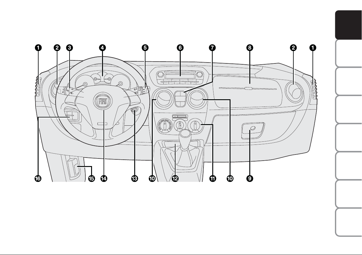
DASHBOARD
The presence and position of the controls, the instruments and the indicators may vary according to the versions.
F0T0070m
fig. 1
1. Vent for air delivery to side windows - 2. Adjustable and directable air vent - 3. Left stalk: external lights control -
4. Instrument and warning light panel - 5. Right stalk: windscreen wiper controls, rear window wiper, trip computer - 6. Sound sys-
tem (for versions/markets, where provided) - 7. Emergency light switch, rear heated window, ASR / Traction Plus system (for ver-
sions/markets, where provided) on/off switch, rear swingdoor unlock device (for versions/markets, where provided) - 8. Airbag on
passenger’s side (for versions/markets, where provided) - 9. Glove box/oddment compartment (for versions/markets, where provided) - 10. Adjustable and directable air vents - 11. HVAC controls - 12. Glove box - 13. Ignition device - 14. Airbag on driver’s
side - 15. Stalk for opening bonnet - 16. Control panel: fog lights/rear fog light/headlight position adjustment/display
DASHBOARD
AND CONTROLS
SAFETY
STARTING
AND DRIVING
WARNING
MESSAGES
LIGHTS AND
IN AN
EMERGENCY
AND CARE
MAINTENANCE
TECHNICAL
SPECIFICATIONS
INDEX
5
Page 7
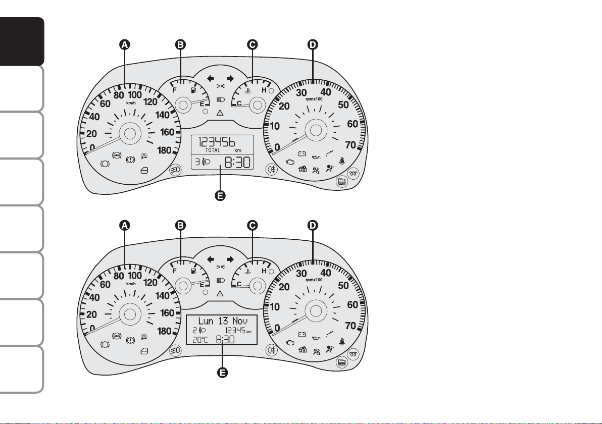
INSTRUMENT PANEL
DASHBOARD
AND CONTROLS
SAFETY
STARTING
AND DRIVING
Versions with digital display
A Speedometer (speed indicator)
B Fuel level gauge with reserve warning
light
C Engine coolant temperature gauge and
excessive temperature warning light
D Rev counter
E Digital display
mcWarning lights supplied in diesel
versions only
WARNING
MESSAGES
LIGHTS AND
IN AN
EMERGENCY
AND CARE
MAINTENANCE
TECHNICAL
SPECIFICATIONS
INDEX
6
fig. 2
fig. 3
F0T0072m
F0T0071m
Versions with multifunctional
display
A Speedometer (speed indicator)
B Fuel level gauge with reserve warning
light
C Engine coolant temperature gauge and
excessive temperature warning light
D Rev counter
E Multifunctional display
mcWarning lights supplied in diesel
versions only
Page 8

SYMBOLS
Special coloured labels have been attached
near or on some of the components of
your vehicle. These labels bear symbols
that draw your attention to the precautions required when handling the component in question.
The inner surface of the engine bonnet
includes a label with the different symbols
used.
THE FIAT CODE SYSTEM
This is an electrical engine locking system
which increases protection against attempted theft of the vehicle. It is automatically activated when the ignition key
is extracted.
Each time the vehicle is started turning the
ignition key to MAR, the Fiat CODE system control unit sends a recognition code
to the engine control unit to deactivate
the inhibitor.
If, during ignition, the code is not correctly
recognized, a warning light Y is lit on the
instrument panel.
In this case, turn the key to STOP and
then back to MAR. Try with the other
keys provided if the problem persists. If
the engine will not start up after this operation, run the emergency start procedure (see chapter “In an emergency”) and
then contact the Fiat Dealership.
IMPORTANT Each key has its own code
which must be stored by the system ECU.
Contact the Fiat Dealership to have new
keys (up to eight) stored with the code.
THE WARNING LIGHT
(or symbol on the display)
GOES ON DURING TRAVEL
❒ If the warning light
display) turns on, the system is running
a self-test (for example for a voltage
drop). The first time you stop the vehicle, turn the ignition key to STOP and
then to MAR. If no failure is detected,
the warning light Ydoes not light up.
❒ If the warning light
the display) remains steadily lit, repeat
the procedure above leaving the key in
the STOP position for over 30 seconds. If the problem persists, contact
the Fiat Dealership.
❒ If the warning light
the display) stays on, the code is not acknowledged. In this case, return the key
to STOP and then to MAR; try with
the other keys provided if the problem
persists. If the engine will not start up
after this operation, run the emergency
start procedure (see chapter “In an
emergency”) and then contact the Fiat
Dealership.
Y
Y
(or symbol on the
(or symbol on
Y
(or symbol on
Y
DASHBOARD
AND CONTROLS
SAFETY
STARTING
AND DRIVING
WARNING
MESSAGES
LIGHTS AND
IN AN
EMERGENCY
AND CARE
MAINTENANCE
The electronic components
inside the key may be damaged if the key is subjected to
violent shocks.
TECHNICAL
INDEX
7
SPECIFICATIONS
Page 9
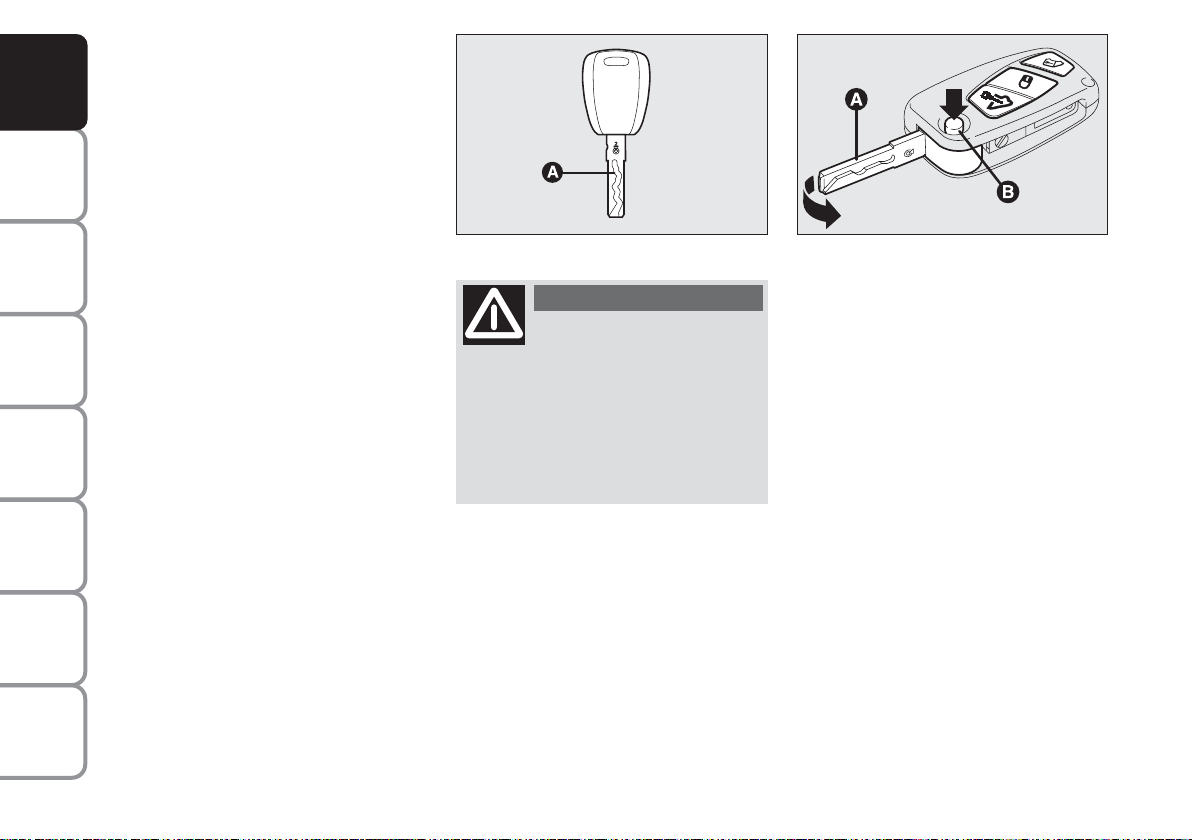
THE KEYS
DASHBOARD
AND CONTROLS
SAFETY
STARTING
AND DRIVING
WARNING
MESSAGES
LIGHTS AND
IN AN
EMERGENCY
AND CARE
MAINTENANCE
TECHNICAL
SPECIFICATIONS
INDEX
KEY WITHOUT REMOTE
CONTROL fig. 4
The metal insert A enables:
❒ the ignition switch;
❒ the door locks;
❒ opening and closing of the fuel plug.
KEY WITH REMOTE CONTROL
fig. 5
(for versions/markets, where provided)
The metal insert A enables:
❒ the ignition switch;
❒ the door locks;
❒ opening and closing of the fuel plug.
To extract the metal insert, press button B.
To fit it back in the handle proceed as follows:
❒ keep button B pressed and move the
metal insert A;
❒ release button B and turn the metal in-
sert A until hearing the proper locking
click.
fig. 4
F0T00002m
WARNING
Press button B only after
moving the key away from
your body, especially your eyes, and
from objects which could get damaged (e.g. your clothes). Do not leave
the key unattended, because someone, a child especially, may accidentally press the button while handling
the key.
The buttonÆactivates the unlocking
of all the doors (including the tailgate/rear swing doors);
The button Á
activates the locking of all
the doors;
The button
∞ activates the unlocking
of the rocker door or the rear swing
doors
(for versions/markets, where pro-
vided)
.
fig. 5
F0T0241m
Opening the windows with the
remote control
(for versions / markets, where provided)
Keep the Æ button (on the key) pressed
for more than 3 seconds to open the windows.
To open the windows completely, keep
the button pressed; if the pressure is suspended, the windows will immediately
stop in their current position.
The same type of opening is also possible
by operating the pawl of the front door
handles.
8
Page 10

Closing the windows with the
remote control
(for versions / markets, where provided)
Keep the Á button (on the key) pressed
for more than 3 seconds to close the windows.
To close the windows completely, keep
the button pressed; if the pressure is suspended, the windows will immediately
stop in their current position.
The same type of closing is also possible
by operating the pawl of the front door
handles.
IMPORTANT During this operation the
window anti-crush safety system is inhibited.
Replacing the battery of the key
with remote control, fig. 6
Battery replacement:
❒ press button A and open the metal in-
sert B;
❒ rotate the screw C to
:
using a small
point screwdriver;
❒ take out the battery case D and replace
the battery E respecting its polarity;
❒ refit the battery case D inside the key
and lock it turning the screw C to
Á
fig. 6
.
Exhausted batteries are
harmful to the environment.
They should be disposed of as
specified by law in the special
containers provided, or take them to
the Fiat Dealership, which will deal
with their disposal.
REQUEST OF ADDITIONAL
REMOTE CONTROLS
The system can recognise up to 8 remote
controls. Should a new remote control be
necessary, contact a Fiat Dealership, taking a personal identity document and the
vehicle ownership documents with you.
F0T0300m
DASHBOARD
AND CONTROLS
SAFETY
STARTING
AND DRIVING
WARNING
MESSAGES
LIGHTS AND
IN AN
EMERGENCY
AND CARE
MAINTENANCE
TECHNICAL
INDEX
9
SPECIFICATIONS
Page 11
DASHBOARD
AND CONTROLS
SAFETY
STARTING
AND DRIVING
WARNING
MESSAGES
LIGHTS AND
IN AN
EMERGENCY
AND CARE
MAINTENANCE
DEAD LOCK SYSTEM
(for versions/markets, where provided)
The dead lock system is a safety device
which prevents door opening from inside
the passenger compartment in case of an
attempted break-in (e.g.: window breaking).
It is the best protection possible against
attempted break-ins. We recommend engaging it whenever the vehicle is parked
and left unattended.
WARNING
Once the dead lock device
has been engaged, doors
cannot be opened from the passenger compartment in any way. For this
reason, make sure there are no persons left inside the vehicle.
WARNING
If the battery of the key with
remote control is down, the
dead lock device can be activated only by fitting the metal insert of the key
in both front door revolving plugs as
described previously: in this case the
dead lock device will stay engaged only on the rear doors.
Engaging the system
The system is automatically enabled on all
the doors by double-pressing the button
Á
positioned on the key with the remote
control.
The system has been successfully enabled
when the direction indicators flash twice.
The system is not enabled if one or more
than one door is not correctly locked.
This prevents any person from getting into the vehicle from an open door, and
locks him/her inside the passenger compartment when the door is closed.
Disengaging the system
The system is disabled automatically on
every door in the following cases:
❒
when unlocking the doors;
❒
when turning the ignition key to MAR.
TECHNICAL
SPECIFICATIONS
INDEX
10
Page 12

ALARM
(for versions/markets, where provided)
In addition to all the remote control functions described above, an alarm has been
installed, which is controlled by a receiver unit located under the dashboard near
the fuse box.
ALARM TRIPPING
The alarm trips in the following cases:
❒ when one of the doors or bonnet is
opened illegitimately (perimeter protection);
❒ when the ignition system is started up
(ignition key rotated to MAR);
❒ when the battery cables are cut;
❒ when someone is moving inside the
passenger compartment (volumetric
protection);
❒ when the vehicle is unusually lift-
ed/tilted.
Depending on the markets where the vehicle is sold, alarm tripping causes either
a siren or direction indicators to go on
(for approx. 26 seconds). Alarm tripping
and the number of cycles depend on the
sales market.
Provision has been made for a maximum
number of acoustic/visual cycles, after
which the system resumes its standard
control function.
Volumetric and anti-lift protections are
disabled by pressing the control button installed on the front dashboard (see paragraph “Anti-lift protections).
IMPORTANT The engine stop function is
guaranteed by the Fiat CODE, which is automatically activated when the ignition key
is extracted from the starter device.
ENABLING THE ALARM
Keep the doors and bonnets closed and
either turn the ignition key to STOP or
remove it. Direct the key with the remote
control towards the vehicle and press button
Á
, then release it.
Excluding some versions for specific markets, the system produces a sound warning (beep) and enables door locking.
Before the alarm is enabled, a self-test is
run. If a failure is detected, the system produces a new acoustic signal and shows a
message on the display (see section
“Warning lights and messages”).
If this is the case, disable the alarm by
pressing button Æ, check correct locking
of the doors, bonnet and boot, and enable
the alarm again by pressing button
Á
.
If a door or the bonnet is not correctly
closed, it will be excluded from the testing by the alarm system.
If the alarm produces an acoustic signal
even when the doors, bonnet and boot
are correctly closed, a failure has occurred
in system operation. Go to a Fiat Dealership.
IMPORTANT If the central door locking
system is engaged using the metal insert
of the key, the alarm is not enabled.
IMPORTANT Originally, the alarm is configured in compliance with the regulations
existing in the different countries.
DASHBOARD
AND CONTROLS
SAFETY
STARTING
AND DRIVING
WARNING
MESSAGES
LIGHTS AND
IN AN
EMERGENCY
AND CARE
MAINTENANCE
TECHNICAL
SPECIFICATIONS
11
INDEX
Page 13

DASHBOARD
AND CONTROLS
SAFETY
STARTING
AND DRIVING
WARNING
MESSAGES
LIGHTS AND
IN AN
EMERGENCY
AND CARE
MAINTENANCE
DISABLING THE ALARM
Press button Æ on the key with the remote control.
The following operations are performed
(excluding some versions):
❒ the direction indicators turn on short-
ly twice;
❒ two short beeps are produced by the
warning buzzer;
❒ the doors are unlocked.
IMPORTANT If the central door locking
system is engaged using the metal insert
of the key, the alarm is not disabled.
fig. 7
F0T0159m
VOLUME-SENSING/
ANTI-LIFT PROTECTION
To ensure correct operation of the protection, it is advisable to fully close the side
windows.
If necessary, the function may be turned
off (e.g. if animals are left in the car) by
pressing key A-fig. 7, located on the front
courtesy light before activating the alarm.
Function deactivation is indicated by the
led located on the key flashing for a few
seconds. If the volume-sensing/anti-lift
protection is turned off, this must be repeated whenever the instrument panel is
turned off.
SIGNALS IN THE EVENT
OF ATTEMPTED BREAK-INS
Whenever a break-in is attempted, a
warning light Y (or symbol on the display) starts blinking on the instrument panel (in some versions a message also appears on the display - see section “Warning lights and messages”).
DISABLING THE ALARM
To permanently disable the alarm (e.g.
during prolonged vehicle shutdown), lock
the vehicle by turning the metal insert of
the key in the door lock. In this case, the
car will not be protected by the alarm system, while the engine immobiliser function
is ensured by the Fiat CODE system
which is automatically activated when the
key is removed from the ignition switch.
IMPORTANT If the battery of the key
with the remote control goes down or the
system fails, the alarm is disabled by placing the key in the ignition system and rotating it to MAR.
TECHNICAL
SPECIFICATIONS
INDEX
12
Page 14

IGNITION DEVICE
The key can be turned to 3 different positions fig. 8:
❒ STOP: the engine is off, the key can be
extracted, the steering is locked. Some
electrical devices (e.g. car radio, central
door locking system, alarm, etc.) are enabled.
❒ MAR: driving position. All electrical de-
vices work regularly.
❒ AVV: engine start.
The ignition device is fitted with a safety
system that forces the driver to return the
ignition key to STOP before repeating the
starting operation, if the engine does not
start up.
fig. 8
F0T0039m
STEERING COLUMN LOCK
Engagement
When the key is at STOP, remove the key
and turn the steering wheel until it locks.
Disengagement
Rock the steering wheel slightly as you
turn the ignition key to MAR.
WARNING
Never extract the key while
the vehicle is moving. The
steering wheel would be locked as
soon as the steering wheel is turned.
This also applies to cases in which the
vehicle is towed. Under no circumstances should after-market operations be carried out involving steering
system or steering column modifications (e.g.: installation of anti-theft
device) that could negatively affect
performance and safety, cause the
lapse of the warranty and also result
in vehicle non-compliance with typeapproval requirements.
DASHBOARD
AND CONTROLS
SAFETY
STARTING
AND DRIVING
WARNING
MESSAGES
LIGHTS AND
IN AN
EMERGENCY
AND CARE
MAINTENANCE
TECHNICAL
INDEX
13
SPECIFICATIONS
Page 15
INSTRUMENTS
DASHBOARD
AND CONTROLS
SAFETY
STARTING
AND DRIVING
WARNING
MESSAGES
LIGHTS AND
IN AN
EMERGENCY
AND CARE
MAINTENANCE
TECHNICAL
SPECIFICATIONS
Instrument background colour and type
may vary according to the version.
fig. 9
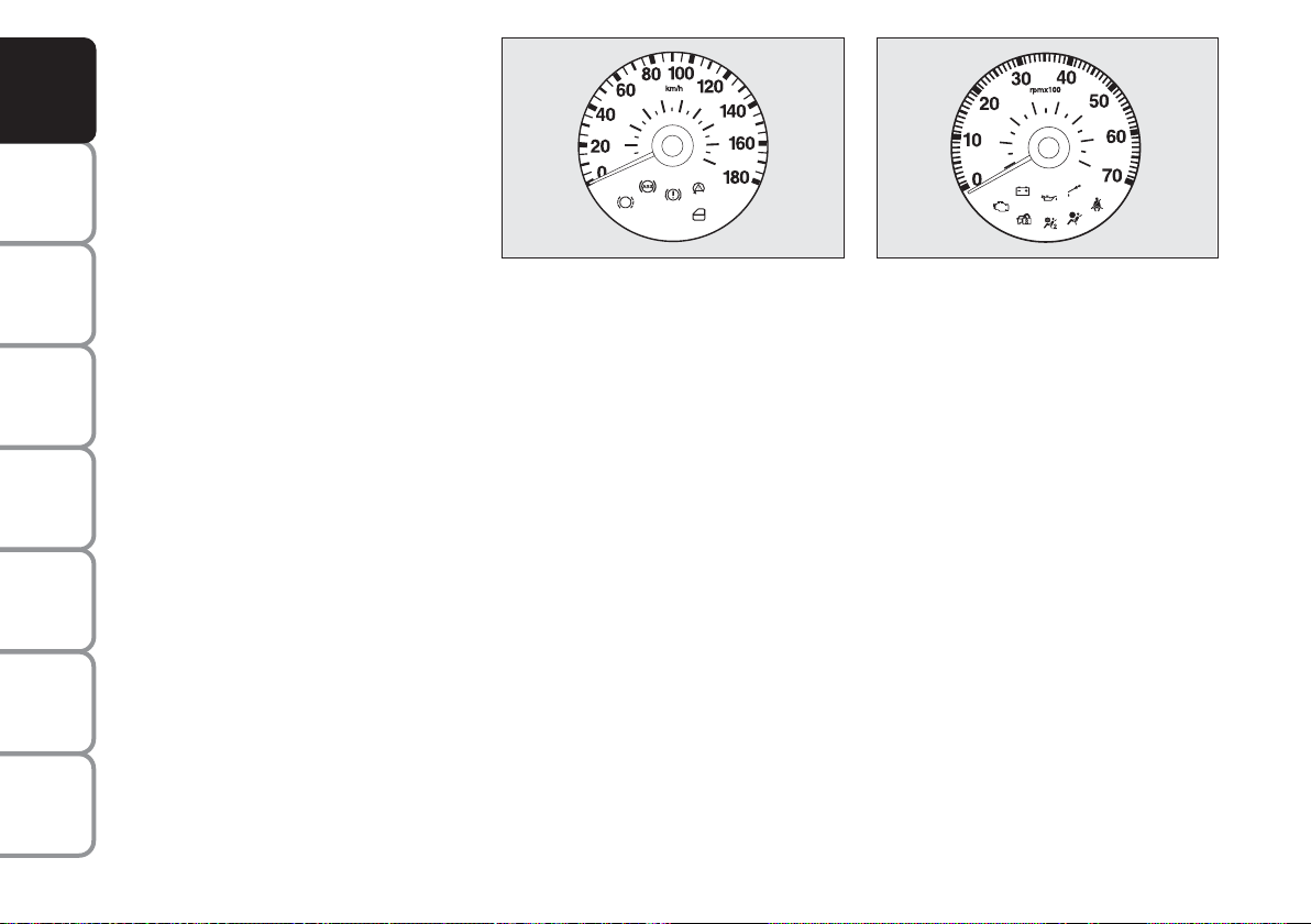
TACHOMETER
(speed indicator) fig. 9
It shows the vehicle speed.
F0T0150m
fig. 10
F0T0151m
REV. COUNTER fig. 10
The rev counter shows the engine rpm.
IMPORTANT The electronic injection control system gradually shuts off the flow of
fuel when the engine is “over-revving” resulting in a gradual loss of engine power.
When the engine is idling, the rev counter
may indicate a gradual or sudden increase
of the speed. This is normal and does not
indicate a fault. It may be caused, for example, by the operation of the climate
control system or fan. In this case, a slow
change in engine speed is used to protect
the battery charge.
INDEX
14
Page 16

FUEL LEVEL INDICATOR
This shows the amount of fuel left in the
fuel tank.
The warning light A-fig. 11 turns on to
indicate that approximately 6 to 7 litres of
fuel are left in the tank.
E - tank empty.
F - tank full (see the instructions provid-
ed in paragraph “Vehicle refuelling” in
this section).
Do not travel when the fuel tank is almost
empty, because this may jeopardize the
catalyst.
IMPORTANT The needle will point to E
and warning light A will blink to indicate a
fault in the system. Go to a Fiat Dealership to have the system checked.
fig. 11
F0T0152m
ENGINE COOLANT
TEMPERATURE INDICATOR
This shows the temperature of the engine
coolant fluid and starts working when the
fluid temperature exceeds approx. 50°C.
Under normal conditions, the needle
should hover around the middle of the
scale according to the working conditions
of the vehicle.
C - Low engine coolant temperature.
H - High engine coolant temperature.
Turning on of the warning light B-fig. 11
(along with a message on the display) indicates that the coolant fluid temperature
is too high. In this case, stop the engine
and contact a Fiat Dealership.
If the needle indicating the
engine coolant temperature
reaches the red area, stop the
engine immediately and con-
tact a Fiat Dealership.
DASHBOARD
AND CONTROLS
SAFETY
STARTING
AND DRIVING
WARNING
MESSAGES
LIGHTS AND
IN AN
EMERGENCY
AND CARE
MAINTENANCE
TECHNICAL
INDEX
15
SPECIFICATIONS
Page 17
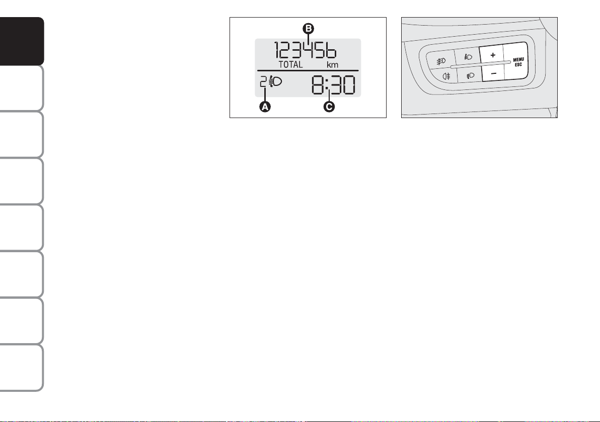
DIGITAL DISPLAY
DASHBOARD
AND CONTROLS
SAFETY
STARTING
AND DRIVING
WARNING
MESSAGES
LIGHTS AND
IN AN
EMERGENCY
AND CARE
MAINTENANCE
TECHNICAL
SPECIFICATIONS
STANDARD SCREEN fig. 12
The standard screen shows the following
information:
A Headlight aiming position (only with
dipped beam headlights on).
B Odometer (covered km or miles).
C Clock (always displayed, even with ig-
nition key removed and front doors
closed).
Note With key removed (when opening
one of the front doors) the display turns
on and shows the time and km or miles
covered for a few seconds.
fig. 12
F0T0017m
CONTROL BUTTONS fig. 13
+ To scroll the displayed menu and the
related options upwards or to increase the value displayed.
MENU Press briefly to display
ESC
the menu and/or to go to next
screen or to confirm the required menu option.
Hold pressed to go back to the
standard screen.
– To scroll the displayed menu and the
related options downwards or to decrease the displayed value.
Note Buttons + and – activate different
functions according to the following situations:
fig. 13
F0T0025m
Light adjustment inside vehicle
– with standard screen enabled, it is possible to adjust the brightness of the instrument panel and sound system.
Setup menu
– to scroll the menu options upwards and
downwards;
– to increase or decrease values during settings.
INDEX
16
Page 18

SETUP MENU fig. 14
The menu comprises a series of functions
arranged in a cycle which can be selected
through buttons + and –, thus gaining access to the different select and setting (setup) operations given in the following paragraphs.
The setup menu can be activated by briefly
pressing button MENU ESC.
Single presses on buttons + and – will
scroll the setup menu options.
Handling modes differ with each other according to the characteristic of the option
selected.
Selecting a menu option
– briefly press button MENU ESC to select the menu option to set;
– press buttons + and – (by single presses) to select the new setting;
– briefly press button MENU ESC to
store the new setting and go back to the
previously selected menu option.
Selecting “Set Clock”
– briefly press button MENU ESC to select the first value to change (hours);
– press buttons + and – (by single presses) to select the new setting;
– briefly press button MENU ESC to
store the new setting and go to the next
setup menu option (minutes);
– after setting the values with the same
procedure, go back to the menu item previously selected.
Prolonged pressing of MENU ESC button
– to quit the setup menu if you are in the
menu;
– to quit the displayed menu if you are setting an option;
– to save the changes to stored settings (and
confirmed by pressing button MENU
ESC).
The setup menu environment is timed;
when quitting the menu due to timing expiry, only the settings stored by the user
are saved (and confirmed by briefly pressing button MENU ESC).
DASHBOARD
AND CONTROLS
SAFETY
STARTING
AND DRIVING
WARNING
MESSAGES
LIGHTS AND
IN AN
EMERGENCY
AND CARE
MAINTENANCE
TECHNICAL
INDEX
17
SPECIFICATIONS
Page 19
DASHBOARD
AND CONTROLS
SAFETY
STARTING
AND DRIVING
WARNING
MESSAGES
LIGHTS AND
IN AN
EMERGENCY
AND CARE
MAINTENANCE
Briefly press button MENU ESC to start browsing
from the standard screen. Press + or – to browse within the menu.
Note. Only the short menu can be accessed while the
vehicle is moving for reasons of safety (“SPEED” setting). Stop the vehicle to access the full menu.
TECHNICAL
SPECIFICATIONS
INDEX
18
F0T1021g
fig. 14
Page 20

Setting the speed limit (SPEEd)
This function is used to set the vehicle
speed limit (km/h or mph); when this limit is exceeded the driver is immediately
alerted (see section “Warning lights and
messages”).
To set the speed limit, proceed as follows:
– briefly press button MENU ESC, the
message (SPEEd) and the previously set
unit (km/h) or (mph) will appear on the
display;
– press button + or – to select speed lim-
it activation (On) or deactivation (OFF);
– if the function has been activated (On),
press buttons + or – to select the required speed limit and then press MENU
ESC to confirm;
Note The speed may be set in the range
from 30 to 200 km/h, or from 20 to 125
mph according to the previously chosen
unit (see “Setting the distance unit”) described below. The setting will increase/decrease by five units each time
button +/– is pressed. Hold button +/–
pressed to increase/decrease the setting
rapidly. When close to the desired value,
press the button as many times as required to complete the regulation.
– Briefly press button MENU ESC to go
back to the menu screen or press the button for long to go back to the standard
screen without storing settings.
To cancel the setting, proceed as follows:
– briefly press button MENU ESC: (On)
will flash on the display;
– press button –: (Off) will flash on the display;
– briefly press button MENU ESC to go
back to the menu screen or press the button for long to go back to the standard
screen without storing settings.
Setting the clock (Hour)
With this function it is possible to set the
clock.
To set the required unit proceed as follows:
– briefly press button MENU ESC,
“hours” will flash on the display;
– press button + or – for setting;
– briefly press button MENU ESC: the
“minutes” start flashing on the display;
– press the button + or – to set the desired value;
– briefly press button MENU ESC to go
back to the menu screen or press the button for long to go back to the standard
screen without storing settings.
Adjusting the buzzer volume
(bUZZ)
This function is used to adjust the volume
of the buzzer triggering in the event of failure/warning indications and when MENU
ESC, + and – buttons are pressed.
To adjust the desired volume proceed as
follows:
– briefly press button MENU ESC, the
display will show the wording (bUZZ);
– press button + or – to select the required volume (volume can be adjusted according to 8 levels).
– briefly press button MENU ESC to go
back to the menu screen or press the button for long to go back to the standard
screen without storing settings.
DASHBOARD
AND CONTROLS
SAFETY
STARTING
AND DRIVING
WARNING
MESSAGES
LIGHTS AND
IN AN
EMERGENCY
AND CARE
MAINTENANCE
TECHNICAL
SPECIFICATIONS
INDEX
19
Page 21
DASHBOARD
AND CONTROLS
SAFETY
STARTING
AND DRIVING
WARNING
MESSAGES
LIGHTS AND
IN AN
EMERGENCY
AND CARE
MAINTENANCE
Setting the unit (Unit)
With this function it is possible to set the
unit.
To set the required unit proceed as follows:
– briefly press button MENU ESC, the
display will show the wording (Unit) and
the previously set unit (km) or (mi);
– press button + or – to select the required distance unit.
– briefly press button MENU ESC to go
back to the menu screen or press the button for long to go back to the standard
screen without storing settings.
Front passenger’s airbag
and side bag
activation/deactivation
(BAG P)
(for versions/markets, where provided)
This function is used to activate/deactivate
the air bag on the passenger’s side.
Proceed as follows:
❒
press button MENU ESC and, after
viewing the message (BAG P OFF) (to
deactivate) or (BAG P On) (to activate)
by pressing buttons + or –, press the
button MENU ESC again;
❒
the confirmation request message will
be displayed;
❒
press buttons + or – to select (YES)
(confirming activation/deactivation) or
(no) (to abort);
❒
briefly press the button MENU ESC
to view a message confirming your selection and go back to the menu screen.
Alternatively, press the button for a
prolonged time and go back to the standard screen without storing the settings.
MENU ESC
+
+
–
–
F0T1016g
MENU ESC
+
+
–
–
F0T1018g
MENU ESC
F0T1014g
F0T1015g
F0T1017g
TECHNICAL
SPECIFICATIONS
INDEX
20
F0T1020g
F0T1019g
Page 22

MULTIFUNCTIONAL
DISPLAY
(for versions/markets, where provided)
The vehicle can be equipped with a multifunctional display that, according to the
settings made, will show useful information when driving.
“STANDARD” SCREEN fig. 15
The standard screen shows the following
information:
A Date.
B Odometer (covered km or miles).
C Clock (always displayed, even with ig-
nition key removed and front doors
closed).
D External temperature.
E Headlight aiming position (only with
dipped beam headlights on).
Note When opening one of the front
doors, the display turns on and shows the
clock and the kilometres or miles covered
for a few seconds.
fig. 15
F0T0019m
CONTROL BUTTONS fig. 16
+ To scroll the displayed menu and the
related options upwards or to increase the value displayed.
MENU Press briefly to display
ESC
the menu and/or go to next
screen or confirm the required
menu option.
Hold pressed to go back to the
standard screen.
– To scroll the displayed menu and the
related options downwards or to decrease the displayed value.
Note. Buttons + and – activate different
functions according to the following situations.
fig. 16
F0T0025m
Light adjustment inside vehicle
– with standard screen enabled, it is possible to adjust the brightness of the instrument panel and sound system.
Setup menu
– to scroll the menu options upwards and
downwards;
– to increase or decrease values during settings.
DASHBOARD
AND CONTROLS
SAFETY
STARTING
AND DRIVING
WARNING
MESSAGES
LIGHTS AND
IN AN
EMERGENCY
AND CARE
MAINTENANCE
TECHNICAL
SPECIFICATIONS
21
INDEX
Page 23

DASHBOARD
AND CONTROLS
SAFETY
STARTING
AND DRIVING
WARNING
MESSAGES
LIGHTS AND
IN AN
EMERGENCY
AND CARE
MAINTENANCE
TECHNICAL
SPECIFICATIONS
SETUP MENU fig. 17
The menu comprises a series of functions
arranged in a cycle which can be selected
through buttons + and –, thus gaining access to the different select and setting (setup) operations given in the following paragraphs. A submenu is provided for some
items (Clock and Unit setting).
The setup menu can be activated by briefly
pressing button MENU ESC.
Single presses on buttons + or – will scroll
the setup menu options.
Handling modes are different according to
the characteristic of the option selected.
Selecting an option of the main menu
without submenu
– Briefly press the button MENU ESC to
select the main menu option to set.
– Press buttons + or – (by single presses) to select the new setting.
– Briefly press the button MENU ESC to
store the new setting and go back to the
main menu option previously selected.
Selecting an option of the main menu
with submenu
– Briefly press the button MENU ESC to
display the first submenu option.
– Press buttons + or – (by single presses) to scroll all the submenu options.
– Briefly press the button MENU ESC to
select the displayed submenu option and
open the relevant setup menu.
– Press buttons + or – (by single presses) to select the new setting for this submenu option.
– Briefly press the button MENU ESC to
store the new setting and go back to the
previously selected submenu option.
Selecting the “Set Date” and “Set time”
– Briefly press button MENU ESC to select the first value to change (e.g. hours
/minutes or year / month / day).
– Press buttons + or – (by single presses) to select the new setting.
– Briefly press button MENU ESC to
store the new setting and go to the next
setup menu option: if this is the last one you
will go back to the previously selected option of the main menu.
Prolonged pressing of MENU ESC button
– to quit the setup menu if you are in the
main menu;
– to quit the main menu if you are in another point of the menu (e.g.: at submenu
option setting level, at submenu level or
at main menu option setting level);
– to save the changes to stored settings (and
confirmed by pressing button MENU
ESC).
The setup menu environment is timed;
when quitting the menu due to timing expiry, only the settings stored by the user
are saved (and confirmed by briefly pressing button MENU ESC).
INDEX
22
Page 24
Example:
Italiano
Nederland
Turkçe
MENU ESC
short pressing
of button
Deutsch
Português
+
English
Español
Français
+
PASSENGER BAG
–
Briefly press button MENU ESC to start browsing
from the standard screen. Press + or – to browse within the menu.
Note. Only the short menu may be accessed for reasons of safety while the vehicle is moving (“Speed Beep”
setting). Stop the vehicle to access the full menu.
+
+
–
–
–
SPEED BEEP
EXIT MENU
TRIP B DATA
–
SET TIME
Example:
Year Month
MENU ESC
+
short pressing
of button
–
Day
+
DASHBOARD
AND CONTROLS
SAFETY
STARTING
AND DRIVING
WARNING
MESSAGES
LIGHTS AND
SERVICE
+
+
(*) This function is only displayed after the SBR system is deactivated by a Fiat Dealership.
–
BELT BUZZER (
–
+
)
*
BUTTON VOL.
–
BUZZER VOLUME
+
AUTOCLOSE
UNITS
–
LANGUAGE
–
–
+
+
SET DATE
SEE RADIO
–
+
–
IN AN
EMERGENCY
+
AND CARE
F0T1000g
fig. 17
MAINTENANCE
TECHNICAL
SPECIFICATIONS
INDEX
23
Page 25

DASHBOARD
AND CONTROLS
SAFETY
STARTING
AND DRIVING
WARNING
MESSAGES
LIGHTS AND
IN AN
EMERGENCY
AND CARE
MAINTENANCE
Speed limit (Speed Beep)
This function is used to set the vehicle
speed limit (km/h or mph); when this limit is exceeded, the driver is immediately
alerted (see section “Warning lights and
messages”).
To set the speed limit, proceed as follows:
– briefly press button MENU ESC, the
display will show the wording (Speed
Beep);
– press button + or – to select speed lim-
it activation (On) or deactivation (Off);
– if the function has been activated (On),
press buttons + or – to select the required speed limit and then press MENU
ESC to confirm.
Note The speed may be set in the range
from 30 to 200 km/h, or from 20 to 125 mph
according to the previously chosen unit (see
“Setting the distance unit”) described below.
The setting will increase/decrease by five
units each time button + / – is pressed. Hold
button +/– pressed to increase/decrease the
setting rapidly. Complete the setting by
briefly pressing the button when the required
setting is approached.
– Briefly press button MENU ESC to go
back to the menu screen or press the button for long to go back to the standard
screen without storing settings.
To cancel the setting, proceed as follows:
– briefly press button MENU ESC: (On)
will flash on the display;
– press button –: (Off) will flash on the display;
– briefly press button MENU ESC to go
back to the menu screen or press the button for long to go back to the standard
screen without storing settings.
Trip B On/Off (Trip B data)
Through this option it is possible to activate (On) or deactivate (Off) the Trip B
(partial trip) display.
For further information see section “Trip
computer”.
For activation / deactivation, proceed as
follows:
– briefly press button MENU ESC: (On)
or (Off) will flash on the display (according to previous setting);
– press button + or – for setting;
– briefly press button MENU ESC to go
back to the menu screen or press the button for long to go back to the standard
screen without storing settings.
TECHNICAL
SPECIFICATIONS
INDEX
24
Page 26

Setting the clock (Set time)
This function enables clock setting using
two submenus: “Time” and “Mode”.
Proceed as follows:
– briefly press button MENU ESC, the
display will show the two sub-menus
“Time” and “Mode”;
– press button + or – to surf the two submenus;
– select the required option and then
press button MENU ESC briefly;
– when accessing the “Hour” submenu:
briefly press button MENU ESC, the
“hours” will flash on the display;
– press button + or – for setting;
– briefly press button MENU ESC, the
“minutes” will flash on the display;
– press button + or – for setting;
– when accessing the “Mode” submenu:
briefly press button MENU ESC : the
previously set display mode will flash on
the display;
– press button + or – to select “24h” or
“12h”.
When you have made the required settings, briefly press button MENU ESC
to go back to the menu screen or press
the button for long to go back to the standard screen without storing settings.
– hold MENU ESC pressed to go back
to the standard screen or main menu according to the points of the menu where
you are at.
Set date (Set date)
This function enables updating the date
(day - month - year).
To update the date proceed as follows:
– briefly press button MENU ESC: “day”
will flash on the display;
– press button + or – for setting;
– briefly press button MENU ESC:
“month” will flash on the display;
– press button + or – for setting;
– briefly press button MENU ESC:
“year” will flash on the display;
– press button + or – for setting.
Note The setting increases or decreases
by one unit each time button + or – is
pressed. Hold the button pressed to increase/decrease the setting rapidly. Complete the setting by briefly pressing the
button when the required setting is approached.
– Briefly press button MENU ESC to go
back to the menu screen or press the button for long to go back to the standard
screen without storing settings.
DASHBOARD
AND CONTROLS
SAFETY
STARTING
AND DRIVING
WARNING
MESSAGES
LIGHTS AND
IN AN
EMERGENCY
AND CARE
MAINTENANCE
TECHNICAL
INDEX
25
SPECIFICATIONS
Page 27

DASHBOARD
AND CONTROLS
SAFETY
STARTING
AND DRIVING
WARNING
MESSAGES
LIGHTS AND
IN AN
EMERGENCY
AND CARE
MAINTENANCE
Audio repetition (See radio)
This function enables viewing information
regarding the sound system on the display.
– Radio: tuned radio station frequency or
RDS message, automatic tuning activation
or AutoSTore;
– Audio CD, MP3 CD: track number;
– CD Changer: CD number and track
number.
To activate (On) or to deactivate (Off)
sound system info displaying proceed as
follows:
– briefly press MENU ESC: (On) or (Off)
will flash on the display (according to previous setting);
– press button + or – for setting;
– briefly press button MENU ESC to go
back to the menu screen or press the button for long to go back to the standard
screen without storing settings.
Automatic central door locking
with vehicle running (Autoclose)
When activated (On), this function automatically locks the doors when the vehicle speed exceeds 5 km/h.
To activate (On) or to deactivate (Off) this
function proceed as follows:
– briefly press button MENU ESC to display one sub-menu;
– briefly press button MENU ESC: (On)
or (Off) will flash on the display (according to previous setting);
– press button + or – for setting;
– briefly press button MENU ESC to go
back to the submenu screen or press the
button for long to go back to the standard
screen without storing settings;
– hold MENU ESC pressed to go back
to the standard screen or main menu according to the points of the menu where
you are at.
Set units (Units)
This function may be used to set the measurement unit in three submenus: “Distances”, “Consumption” and “Temperature”.
To set the required unit proceed as follows:
– briefly press button MENU ESC to display the three sub-menus;
– press button + or – to browse the three
sub-menus;
– select the required submenu and then
briefly press button MENU ESC;
– when accessing the “Distances”submenu:
briefly press MENU ESC: either “km” or
“mi” will appear on the display (according
to the previous setting);
– press button + or – for setting;
– when accessing the “Consumption”submenu:
briefly press MENU ESC: either “km/l ”,
“l/100km” or “mpg” will appear on the display (according to the previous setting);
TECHNICAL
SPECIFICATIONS
INDEX
26
Page 28

If the distance unit set is “km” the fuel consumption unit will be displayed in km/l or
l/100km.
If the distance unit set is “mi” the fuel consumption unit will be displayed in “mpg”.
– press button + or – for setting;
– when accessing the “Temperature”submenu:
briefly press MENU ESC: either “°C” or
“°F” will appear on the display according
to the previous setting;
– press button + or – for setting;
When you have made the required set-
tings, briefly press button MENU ESC to
go back to the menu screen or press the
button for long to go back to the standard
screen without storing settings.
– hold MENU ESC pressed to go back
to the standard screen or main menu according to the points of the menu where
you are at.
Select language (Language)
The messages can be displayed in the following languages: Italian, German, English,
Spanish, French, Portuguese, Turkish and
Dutch.
To set the required language proceed as
follows:
– briefly press button MENU ESC: the
previously set “language” “will flash on the
display”;
– press button + or – for setting;
– briefly press button MENU ESC to go
back to the menu screen or press the button for long to go back to the standard
screen without storing settings.
Adjust the failure/warning buzzer
volume (Buzzer volume)
With this function the volume of the
buzzer accompanying any failure/warning
indication can be adjusted according to 8
levels.
To adjust the desired volume proceed as
follows:
– briefly press button MENU ESC: the
previously set volume “level” will flash on
the display;
– press button + or – for setting;
– briefly press button MENU ESC to go
back to the menu screen or press the button for long to go back to the standard
screen without storing settings.
DASHBOARD
AND CONTROLS
SAFETY
STARTING
AND DRIVING
WARNING
MESSAGES
LIGHTS AND
IN AN
EMERGENCY
AND CARE
MAINTENANCE
TECHNICAL
INDEX
27
SPECIFICATIONS
Page 29

DASHBOARD
AND CONTROLS
SAFETY
STARTING
AND DRIVING
WARNING
MESSAGES
LIGHTS AND
IN AN
EMERGENCY
AND CARE
MAINTENANCE
Adjust the button volume
(Button Vol.)
This function may be used to adjust the
volume of the beep accompanying the activation of buttons MENU ESC, + and
– can be adjusted according to 8 levels.
To adjust the desired volume proceed as
follows:
– briefly press button MENU ESC: the
previously set volume “level” will flash on
the display;
– press button + or – for setting;
– briefly press button MENU ESC to go
back to the menu screen or press the button for long to go back to the standard
screen without storing settings.
S.B.R. buzzer reactivation
(Belt Buzzer)
This function is only displayed after Fiat
Dealership has deactivated the S.B.R. system (see paragraph “S.B.R. system” in section “Safety devices”).
Scheduled Servicing (Service)
Through this function it is possible to display information connected to proper vehicle servicing.
This information is consulted as follows:
– briefly press button MENU ESC: service in km or mi, according to previous
setting, will be displayed (see paragraph
“Units”);
– briefly press button MENU ESC to go
back to the menu screen or press the button for long to go back to the standard
screen.
Note The “Scheduled Service Plan” requires the vehicle to be serviced every
30,000 km (or 18,000 mi). This indication
will appear automatically with the key at
MAR starting from 2,000 km (or 1240 mi)
and will be presented automatically every
200 km (or 124 mi). The indications will
appear more frequently when there are
200 km left. The indication will appear in
kilometres or miles depending on the unit
set. When the next scheduled servicing
is approaching, the message “Service” will
appear on the display followed by the
number of kilometres or miles left when
the key is turned to MAR. Go to the
Fiat Dealership where the “Scheduled Service Plan” operations will be performed
and the message will be reset.
TECHNICAL
SPECIFICATIONS
INDEX
28
Page 30
Passenger front and side airbag
activation/deactivation
(Passenger bag)
(for versions/markets, where provided)
This function is used to activate/deactivate
the airbag on the passenger’s side.
Proceed as follows:
❒
briefly press button MENU ESC and,
after displaying the message “Bag pass:
Off) (to deactivate) or Bag pass: On) (to
activate) by pressing the buttons + and
–, press the button MENU ESC again;
❒
the display will show the confirmation
message;
❒
press buttons + or – to select either
Yes (to confirm activation/deactivation)
or No (to abort);
❒
briefly press the button MENU ESC
to view a message confirming your selection and go back to the menu screen.
Alternatively, press the button for a
prolonged time and go back to the standard screen without storing the settings.
F0T1003g
F0T1008g
F0T1010g
MODE
+
–+–
MODE
+
–+–
MODE
F0T1009g
F0T1004g
F0T1009g
F0T1011g
DASHBOARD
AND CONTROLS
SAFETY
STARTING
AND DRIVING
WARNING
MESSAGES
LIGHTS AND
IN AN
EMERGENCY
AND CARE
MAINTENANCE
F0T1012g
F0T1013g
TECHNICAL
INDEX
29
SPECIFICATIONS
Page 31

DASHBOARD
AND CONTROLS
SAFETY
STARTING
AND DRIVING
WARNING
MESSAGES
LIGHTS AND
IN AN
EMERGENCY
AND CARE
MAINTENANCE
Exit Menu
This is the last function that closes the setting cycle listed in the initial menu screen.
Briefly press button MENU ESC to go
back to the standard screen without storing settings.
Press button – to return to the first menu
option (Speed Beep).
TRIP COMPUTER
General features
The “Trip computer” is used to display information on vehicle operation when the
key is turned to MAR. This function allows to define two separate trips called
“Trip A” and “Trip B” for monitoring the
“complete mission” of the vehicle (trip) in
a reciprocally independent manner. Both
functions are resettable (reset - start of
new mission).
“Trip A” is used to display data relating to:
– Range
– Trip distance
– Average consumption
– Instant consumption
– Average speed
– Travel time (driving time).
“Trip B” is supplied on versions having a
multifunctional display and is used to display data relating to:
– Trip distance B
– Average consumption B
– Average speed B
– Travel time B (driving time).
Note “Trip B” functions may be disabled
(see paragraph “Trip B on”). “Range” and
“Instant consumption” cannot be reset.
TECHNICAL
SPECIFICATIONS
INDEX
30
Page 32

Values displayed
Range
Indicates the travel distance left before the
vehicle runs out of the fuel in the tank.
The message “----” will appear on the display in the following cases:
– value lower than 50 km (or 30 mi)
– vehicle left parked with engine running
for long.
IMPORTANT Changes of the range value
can be affected by many factors: driving
style (see paragraph “Driving style” in section “Starting and driving”), type of route
(motorway, urban cycle, mountain roads,
etc…), conditions of use of the vehicle
(load, tyre pressure, etc…). Trip planning
must take into account the above notes.
Trip distance
Indicates the distance covered from the
start of a new mission.
Average consumption
Represents the approximate average consumption from the start of a new mission.
Instant consumption
Indicates the fuel consumption. The value is constantly updated. The message
“----” will appear on the display if the vehicle is parked with the engine running.
Average speed
Represents the vehicle average speed as a
function of the overall time elapsed since
the start of a new mission.
Trip time
Indicates the time elapsed since the start
of a new mission.
IMPORTANT If information is not available, the message “----” will appear instead
of the Trip Computer values. Counting of
the different values will be resumed regularly when normal operation is restored.
This will not cause any resetting of the values displayed before the failure nor starting a new mission.
DASHBOARD
AND CONTROLS
SAFETY
STARTING
AND DRIVING
WARNING
MESSAGES
LIGHTS AND
IN AN
EMERGENCY
AND CARE
MAINTENANCE
TECHNICAL
INDEX
31
SPECIFICATIONS
Page 33

DASHBOARD
AND CONTROLS
SAFETY
STARTING
AND DRIVING
WARNING
MESSAGES
LIGHTS AND
IN AN
EMERGENCY
AND CARE
MAINTENANCE
fig. 18
F0T0038m
TRIP control button fig. 18
Button TRIP located on the top of the
right steering column stalk is used (with
ignition key at MAR) to display and reset the previously described values to start
a new mission:
– short pressing to display the different
values;
– prolonged pressing to reset and then
start a new mission.
New mission
The new mission begins after:
– “manual” resetting by the user, by pressing the relevant button;
– “automatic” resetting, when the “Trip
distance” reaches 3999.9 km or 9999.9 km
(according to the type of display) or when
the “Trip time” reaches 99.59 (99 hours
and 59 minutes);
– disconnection/reconnection of the battery.
IMPORTANT Value resetting from the
screens of “Trip A” makes it possible to
exclusively reset the data regarding this
function.
IMPORTANT Value resetting from the
screens of “Trip B” makes it possible to
exclusively reset the data regarding this
function.
“Start trip” procedure
With ignition key on MAR, press and hold
button TRIP pressed for over 2 seconds
to reset.
Exit Trip
To exit the Trip function: hold MENU
ESC pressed for longer than 2 seconds.
TECHNICAL
SPECIFICATIONS
INDEX
32
Page 34

SEATS
A
FRONT SEATS fig. 19
WARNING
All adjustments must be
made with the vehicle sta-
tionary.
Longitudinal adjustment
Lift lever A and push the seat forwards
and backwards: your arms should rest on
the steering wheel rim while you are driving.
WARNING
After releasing the adjust-
ment lever, always check
that the seat is locked on the runners
by trying to move it back and forth. If
it is not locked, the seat may move
unexpectedly and make you lose control of the vehicle.
Adjusting backrest tilting
Turn knob B.
fig. 19
F0T0153m
Adjustment of driver’s seat height
(for versions/markets, where provided)
Operate lever C to lift or lower the rear
area of the cushion to achieve the most
comfortable driving position.
IMPORTANT Adjustment must be carried out by the driver sitting in the relevant seat.
fig. 20
F0T0205m
Lumbar adjustment of driver’s
seat
(for versions/markets, where provided)
Turn knob D to customize the position of
the back against the backrest.
Seat warming
(for versions/markets, where provided)
Place the key in the position MAR and
press button A-fig. 20 to enable/disable
this function.
When the function is enabled, the LED on
the button turns on.
DASHBOARD
AND CONTROLS
SAFETY
STARTING
AND DRIVING
WARNING
MESSAGES
LIGHTS AND
IN AN
EMERGENCY
AND CARE
MAINTENANCE
TECHNICAL
SPECIFICATIONS
INDEX
33
Page 35

RECESSING FOLDABLE
PASSENGER’S SEAT
(for versions/markets, where provided)
DASHBOARD
AND CONTROLS
Some versions have the passenger’s seat
which folds into a recessed compartment.
IMPORTANT Only move the seat if there
SAFETY
are no passengers in the rear seats.
STARTING
AND DRIVING
WARNING
MESSAGES
LIGHTS AND
IN AN
EMERGENCY
AND CARE
MAINTENANCE
TECHNICAL
SPECIFICATIONS
INDEX
34
Folding the seat
To fold the seat proceed as follows:
❒ open the door on the passenger’s side;
❒ pull the two levers A-fig. 21 on the
sides of the seat and tip it forward following the indications of the arrow;
❒ then, push the backrest B-fig. 22 down:
the seat is now folded all the way down
in the “table” position;
❒ pull the lever C-fig. 23 and push the
backrest down as much as possible: the
seat is now completely folded.
fig. 21
F0T0274m
fig. 22
fig. 23
F0T0163m
F0T0164m
Page 36

DASHBOARD
AND CONTROLS
SAFETY
fig. 24
F0T0165m
Putting the seat back in position
To bring the seat back to the normal position proceed as follows:
❒ grab the lever A-fig. 24 and lift the
backrest;
❒ grab the levers B-fig. 25 and lift the back-
rest further more up.
WARNING
When the passenger’s seat is
in recessed position, the resulting space cannot be used as a
loading compartment. During vehicle
travel we recommend that all objects
be removed or secured so that they
do not become an obstacle or pose
a risk during driving.
fig. 25
F0T0237m
WARNING
If there is no partition be-
tween the cabin and the
loading compartment, large objects
or packs may partially occupy the
passenger compartment. Make sure
that these objects or packs are secured by the supplied restraint devices, therefore not being an obstacle
or posing risks during driving.
ACCES TO REAR SEATS
Access to the rear seats is gained by opening one of the rear sliding doors (see instructions provided in paragraph “Doors”
of this section).
fig. 25a
F0T0340m
PARTITION
(4 seater multi transporter
versions)
FIXED PARTITION fig. 25a
It is installed behind the backrest of the
rear seats.
STARTING
AND DRIVING
WARNING
LIGHTS AND
IN AN
EMERGENCY
AND CARE
MAINTENANCE
TECHNICAL
SPECIFICATIONS
INDEX
35
MESSAGES
Page 37

HEAD RESTRAINTS
A
DASHBOARD
AND CONTROLS
SAFETY
STARTING
AND DRIVING
WARNING
MESSAGES
LIGHTS AND
IN AN
EMERGENCY
AND CARE
MAINTENANCE
TECHNICAL
SPECIFICATIONS
FRONT fig. 26
Head restraints are adjustable in height
and they lock automatically in the required
position.
❒ Upward adjustment Raise the head re-
straint until you hear it click in position.
❒ Downward adjustment Press button A
and lower the head restraint.
WARNING
Perform these operations
only when the car is stationary
and the engine is not running.
Remember that the head restraints
should be adjusted to support the
back of your head and not your neck.
Only in this position do they exert
their protective action.
To optimise head restraint protective
action, adjust the backrest upright
and keep your head as close as
possible to the head restraint.
fig. 26
F0T0053m
REAR HEAD RESTRAINTS
fig. 27 - 27a
(for versions/markets, where provided)
Lift the rear head restraints to use them.
To bring the head restraint back to its
non-use position, press buttons A and
push the head restraint down into the
backrest.
To extract the head restraint, raise it until hearing the click (position of use) indicating that it has come all the way out.
IMPORTANT During travel rear seat passengers must always set the head restraints in the “all the way out” position.
fig. 27
fig. 27a - 4 seater multi
transporter versions
F0T0054m
F0T0341m
INDEX
36
Page 38

STEERING WHEEL
REARVIEW MIRRORS
In some versions the steering wheel position can be adjusted both axially and in
height.
Proceed as follows:
❒ release the lever A-fig. 28 pushing it
forwards (position 1);
❒ adjust the steering wheel as required;
❒ lock the lever A pulling it towards the
steering wheel (position 2).
WARNING
Perform these adjustments
only when the vehicle is sta-
tionary and the engine is not running.
WARNING
Under no circumstances
should aftermarket operations involving steering system or
steering column modifications (e.g.:
installation of anti-theft device) be
carried out that could badly affect
performance and safety. This also
causes the warranty to become null
and void and results in vehicle noncompliance with type-approval requirements.
fig. 28
fig. 29
F0T0040m
F0T0027m
INTERAL MIRROR fig. 29
(for versions/markets, where provided)
The mirror is fitted with a safety device
that causes its release in the event of a violent crash.
It can be moved using lever A to two different positions: normal or antiglare.
DASHBOARD
AND CONTROLS
SAFETY
STARTING
AND DRIVING
WARNING
MESSAGES
LIGHTS AND
IN AN
EMERGENCY
AND CARE
MAINTENANCE
TECHNICAL
SPECIFICATIONS
INDEX
37
Page 39

DASHBOARD
B
C
D
AND CONTROLS
SAFETY
STARTING
AND DRIVING
WARNING
MESSAGES
LIGHTS AND
IN AN
EMERGENCY
AND CARE
MAINTENANCE
TECHNICAL
SPECIFICATIONS
INDEX
38
fig. 30
F0T0042m
DOOR MIRRORS
Manual mirror folding
When required (for example when the
mirror becomes an obstacle in narrow
spaces) it is possible to fold the mirror
moving it from position A-fig. 30 to position B.
WARNING
During vehicle travel the mirrors must always be posi-
tioned as shown in A-fig. 30.
Rear door mirrors are curved
WARNING
and slightly alter the percep-
tion of distance.
fig. 31
F0T0194m
Manual regulation
From the vehicle inside pull the lever Afig. 31.
fig. 32
F0T0041m
Electrical regulation
(for versions/markets, where provided)
Door mirrors are regulated electrically
only if the ignition key is in position MAR.
Proceed as follows:
❒ use the diverter A-fig. 32 to select the
desired mirror (right or left hand):
❒ move the diverter A in position B and
direct the left-hand side rear door mirror;
❒ move the diverter A in position D and
direct the right-hand side rear door
mirror.
After this regulation, reposition the diverter A in the intermediate lock position
C.
Page 40

HEATING AND CLIMATE CONTROL SYSTEM
DASHBOARD
AND CONTROLS
SAFETY
STARTING
AND DRIVING
WARNING
MESSAGES
LIGHTS AND
IN AN
EMERGENCY
AND CARE
MAINTENANCE
fig. 33
1. Upper fixed vent - 2. Adjustable central vents - 3. Fixed side vent - 4. Adjustable side vents - 5. Vents in feet area
F0T0148m
TECHNICAL
INDEX
39
SPECIFICATIONS
Page 41

DASHBOARD
AND CONTROLS
SAFETY
STARTING
AND DRIVING
WARNING
MESSAGES
LIGHTS AND
IN AN
EMERGENCY
AND CARE
MAINTENANCE
TECHNICAL
SPECIFICATIONS
INDEX
40
fig. 34
F0T0031m
CENTRAL AND SIDE VENTS
fig. 34-35
A - Adjustable side vent.
B - Fixed vent for side windows.
C - Adjustable central vents.
fig. 35
F0T0030m
To use vents A and C operate the relevant lever to turn them in the desired position.
Page 42

HEATING AND VENTILATION
CONTROLS fig. 36
A air temperature adjustment knob (for
hot/cold air mixing)
B internal air recirculation on/off button
C fan activation knob
D air distribution knob.
CLIMATE COMFORT
The knob D enables the air in the vehicle
to reach all the areas in the passenger
compartment according to 5 distribution
levels:
supply of air from central vents and side
outlets;
feet heating and face refreshing (bilevel
ß
function);
quicker heating of passenger com-
©
partment;
warming of passenger compartment
®
and windscreen demisting at the same
time;
-
demisting and defrosting of windscreen and front side windows.
fig. 36
F0T0074m
DASHBOARD
AND CONTROLS
SAFETY
STARTING
AND DRIVING
WARNING
MESSAGES
LIGHTS AND
IN AN
EMERGENCY
AND CARE
MAINTENANCE
TECHNICAL
SPECIFICATIONS
41
INDEX
Page 43

DASHBOARD
AND CONTROLS
SAFETY
STARTING
AND DRIVING
WARNING
MESSAGES
LIGHTS AND
IN AN
EMERGENCY
AND CARE
MAINTENANCE
HEATING
Proceed as follows:
❒ turn knob A all the way to the right
(line on -);
❒ turn knob C to the required speed;
❒ turn knob D on:
to warm the feet and demist the
®
windscreen at the same time;
to deliver air to the feet area and re-
ß
lease cooler air from central vents
and outlets on the dashboard;
to heat the area quickly.
©
FAST HEATING
Proceed as follows:
❒ close all the vents on the dashboard;
❒ turn knob A on
❒ turn knob C on 4
❒ turn knob D on
-
©
-
.
;
;
FAST DEMISTING/
DEFROSTING OF WINDSCREEN
AND FRONT SIDE WINDOWS
(MAX-DEF function)
Proceed as follows:
❒ turn knob A on
❒ turn knob C on 4
❒ turn knob D on
❒ turn cursor B on
After demisting/defrosting, operate the
standard controls to restore the required
comfort conditions.
-
-
-
;
;
;
.
Window demisting
In the event of considerable external moisture and/or rain and/or considerable differences in temperature inside and outside the passenger compartment, perform
the following preventive demisting procedure:
❒ turn cursor B on
❒ turn knob A on
❒ turn knob C on 2;
❒ turn knob D on
bility to reach position ®if the windows are not misty.
Y
;
-
;
-
having the possi-
TECHNICAL
SPECIFICATIONS
INDEX
42
Page 44

REGULATING THE
FAN SPEED
To ventilate the passenger compartment
properly proceed as follows:
❒ fully open the central air vents and side
outlets;
❒ turn knob A to the blue section;
❒ turn cursor B on
;
❒ turn knob C to the required speed;
❒ turn knob D on
¥
.
ACTIVATION OF INTERNAL
AIR RECIRCULATION
Turn cursor B to position
v
.
It is advisable to activate air recirculation
during vehicle stops in queues or tunnels
to prevent the introduction of polluted air
from the outside.
Do not use the function for a long time,
particularly if there are many passengers
on board, to prevent the windows from
misting up.
IMPORTANT The internal air recirculation system makes it possible to reach the
required “heating” or “cooling” conditions
faster. Do not use the air recirculation
function on rainy/cold days as it would
considerably increase the possibility of the
windows misting inside.
fig. 37
F0T0048m
DEMISTING/DEFROSTING OF REAR
HEATED WINDOW AND DOOR
MIRRORS (where provided) fig. 37
Press button ( to engage this function.
When the function is active, a led on the
button goes on.
To disable this function, press the button
( again.
IMPORTANT Do not apply stickers on
the inside of the rear window over the
heating filaments to avoid damage that
might cause it to stop working properly.
DASHBOARD
AND CONTROLS
SAFETY
STARTING
AND DRIVING
WARNING
MESSAGES
LIGHTS AND
IN AN
EMERGENCY
AND CARE
MAINTENANCE
TECHNICAL
INDEX
43
SPECIFICATIONS
Page 45

MANUAL CLIMATE CONTROL SYSTEM
(for versions/markets, where provided)
DASHBOARD
AND CONTROLS
SAFETY
STARTING
AND DRIVING
WARNING
MESSAGES
LIGHTS AND
IN AN
EMERGENCY
AND CARE
MAINTENANCE
TECHNICAL
SPECIFICATIONS
INDEX
fig. 38
CONTROLS fig. 38
A air temperature adjustment knob (for
hot/cold air mixing);
B internal air recirculation on/off button;
F0T0029m
C fan and climate control system activa-
tion/deactivation knob;
D air distribution knob.
CLIMATE COMFORT
The knob D enables the air in the vehicle
to reach all the areas in the passenger
compartment according to 5 distribution
levels:
supply of air from central vents and side
outlets;
feet heating and face refreshing (bilevel
ß
function);
quicker heating of passenger com-
©
partment;
warming of passenger compartment
®
and windscreen demisting at the same
time;
-
demisting and defrosting of windscreen and front side windows.
HEATING
Proceed as follows:
❒ turn knob A all the way to the right
(line on -);
❒ turn knob C to the required speed;
❒ turn knob D on:
to warm the feet and at the same time
®
demist the windscreen;
to deliver air to the feet area and re-
ß
lease cooler air from central vents
and outlets on the dashboard;
to heat the area quickly.
©
44
Page 46

FAST HEATING
Proceed as follows:
❒ close all the vents on the dashboard;
❒ turn knob A on
❒ turn knob C on 4
❒ turn knob D on
-
ß
-
.
;
;
FAST DEMISTING/
DEFROSTING OF WINDSCREEN
AND FRONT SIDE WINDOWS
(MAX-DEF function)
Proceed as follows:
❒ turn knob A on
❒ turn knob C on 4
❒ turn knob D on
❒ turn cursor B on
-
-
-
;
;
;
.
After demisting/defrosting, operate the
standard controls to restore the required
comfort conditions.
IMPORTANT The climate control system
is very useful for faster demisting because
it dries the air. Regulate the controls as
described above and engage the climate
control by pressing knob C.
Window demisting
In the event of considerable external moisture and/or rain and/or considerable differences in temperature inside and outside the passenger compartment, perform
the following preventive demisting procedure:
❒ turn cursor B on
❒ turn knob A on
-
;
;
❒ turn knob C on 2;
❒ turn knob D on
-
having the possibility to reach position ®if the windows are not misty.
REGULATING THE FAN SPEED
To ventilate the passenger compartment
properly proceed as follows:
❒ fully open the central air vents and side
outlets;
❒ turn knob A to the blue section;
❒ turn cursor B on
;
❒ turn knob C to the required speed;
❒ turn knob D on
©
.
ACTIVATION OF
INTERNAL AIR
RECIRCULATION
Turn cursor B to position
v
.
It is advisable to activate air recirculation
during vehicle stops in queues or tunnels
to prevent the introduction of polluted air
from the outside.
Do not use the function for a long time,
particularly if there are many passengers
on board, to prevent the windows from
misting up.
IMPORTANT The internal air recirculation system makes it possible to reach the
required “heating” or “cooling” conditions faster. Do not use the air recirculation function on rainy/cold days as it would
considerably increase the possibility of the
windows misting inside.
DASHBOARD
AND CONTROLS
SAFETY
STARTING
AND DRIVING
WARNING
MESSAGES
LIGHTS AND
IN AN
EMERGENCY
AND CARE
MAINTENANCE
TECHNICAL
SPECIFICATIONS
45
INDEX
Page 47

DASHBOARD
AND CONTROLS
SAFETY
STARTING
AND DRIVING
WARNING
MESSAGES
LIGHTS AND
IN AN
EMERGENCY
AND CARE
MAINTENANCE
CLIMATE CONTROL (cooling)
Proceed as follows:
❒ turn knob A to the blue section;
❒ turn knob C on 4
❒ turn cursor B on
❒ turn knob D on
©
-
v
;
;
;
❒ turn knob C.
Regulating cooling
Proceed as follows:
❒ turn cursor B on
;
❒ turn knob A to the right to increase the
temperature;
❒ turn knob C to the left to reduce the
fan speed.
fig. 39
F0T0048m
DEMISTING/DEFROSTING
OF REAR HEATED WINDOW
AND DOOR MIRRORS
fig. 39
(for versions/markets, where provided)
Press button ( to engage this function.
When the function is active, a led on the
button goes on.
To disable this function, press the button
( again.
IMPORTANT Do not apply stickers on
the inside of the rear window over the
heating filaments to avoid damage that
might cause it to stop working properly.
SERVICING THE SYSTEM
Let the climate control system run for at
least 10 minutes every month during the
winter. Have the system inspected at a Fiat Dealership before the summer.
TECHNICAL
SPECIFICATIONS
INDEX
46
Page 48

EXTERNAL LIGHTS
The left-hand lever fig. 40 groups the controls for the external lights.
The external lights can only be switched
on when the ignition key is at MAR.
The instrument panel and the various controls on the dashboard will come on when
the external lights are switched on.
LIGHTS OFF
Knurled ring turned to position O.
SIDELIGHTS - TAILLIGHTS
Turn the knurled ring to position 6. The
warning light
will come on.
3 on the instrument panel
fig. 40
F0T0220m
PARKING LIGHTS
These lights can only be turned on with ignition key at STOP or removed, by moving the left stalk knurled ring first to O and
then to 6 or 2.
Warning light
3 on the instrument pan-
el will turn on. To select the right or left
lights use the direction indicator stalk.
DIPPED BEAM HEADLIGHTS
Turn the knurled ring to position 2. The
warning light
3 on the instrument panel
will come on.
MAIN BEAM HEADLIGHTS
When the knurled ring is at
2, pull the
lever towards the steering wheel (2ndunstable position). The warning light 1on
the instrument panel will come on.
To turn the main beams off, pull the lever
again towards the steering wheel (dipped
beams will turn on).
FLASHING THE HEADLIGHTS
Pull the lever towards the steering wheel
st
(1
unstable position) regardless of the
position of the knurled ring. The warning
light 1 on the instrument panel will come
on.
DASHBOARD
AND CONTROLS
SAFETY
STARTING
AND DRIVING
WARNING
MESSAGES
LIGHTS AND
IN AN
EMERGENCY
AND CARE
MAINTENANCE
TECHNICAL
INDEX
47
SPECIFICATIONS
Page 49

DASHBOARD
AND CONTROLS
SAFETY
STARTING
AND DRIVING
WARNING
MESSAGES
LIGHTS AND
IN AN
EMERGENCY
AND CARE
MAINTENANCE
TECHNICAL
SPECIFICATIONS
DIRECTION INDICATORS
fig. 41
Push the stalk to (stable) position:
❒ up (position 1): right-hand indicator
ON;
❒ down (position 2): left-hand indicator
ON.
Warning light
or ¥will blink on the in-
Î
strument panel.
Direction indicators are switched off automatically when the steering wheel of the
vehicle is straightened.
If you want the indicator to flash briefly to
show that you are about to change lane,
which requires minimum steering wheel
rotation, move the stalk up or down without clicking into position (unstable position). When released, the stalk will return
to its home position.
fig. 41
F0T0157m
Lane change function
If you want to signal that you are changing
lane, bring the left stalk in unstable position for shorter than half a second.
The direction indicator on the selected
side flashes three times and then switches off automatically.
“FOLLOW ME HOME”
DEVICE
This device allows the illumination of the
space in front of the vehicle for a preset
time.
Activation
With the ignition key on STOP or re-
moved, pull the stalk towards the steering
wheel within 2 minutes from when the en-
gine is turned off.
At each single movement of the stalk, the
lights stay on for further 30 seconds up to
a maximum of 210 seconds; then the lights
are switched off automatically.
Warning light
3 on the instrument pan-
el lights up, and the corresponding mes-
sage appears on the display (see “Warn-
ing lights and messages”), whenever the
stalk is moved. The warning light goes out
when the stalk is operated and stays on
until the device is automatically deactivat-
ed. The time during which the lights stay
on can only be increased by operating the
stalk.
Deactivation
Keep the stalk pulled towards the steer-
ing wheel for more than 2 seconds.
INDEX
48
Page 50

WINDOW WASHING
The right stalk fig. 42 controls windscreen
wiper/washer and rear heated window
wiper/washer operation (for versions/
markets, where provided).
WINDSCREEN WIPER\WASHER
The device can work only when the ignition key is on MAR.
The right lever can take four different positions:
O windscreen wiper off;
intermittent;
≤
continuous slow;
≥
continuous fast.
¥
fig. 42
F0T0158m
Move the lever to position A-fig. 42 (unstable) to limit operation during the time
when the lever is held in this position. The
lever will return to position and the wiper
will be automatically stopped when released.
With the knurled ring in position ≤the
windscreen wiper will automatically adapt
to the speed of the vehicle.
With windscreen wiper on and reverse
gear engaged, the rear window wiper is
automatically activated.
Do not use the windscreen
wiper to remove layers of
snow or ice from the wind-
screen. In such conditions, the
windscreen wiper may be subjected to
excessive stress and the motor protection which prevents operation for a few
seconds may trip. If the issue persists,
contact the Fiat Dealership.
DASHBOARD
AND CONTROLS
SAFETY
STARTING
AND DRIVING
WARNING
MESSAGES
LIGHTS AND
IN AN
EMERGENCY
AND CARE
MAINTENANCE
TECHNICAL
INDEX
49
SPECIFICATIONS
Page 51

DASHBOARD
AND CONTROLS
SAFETY
STARTING
AND DRIVING
WARNING
MESSAGES
LIGHTS AND
IN AN
EMERGENCY
AND CARE
MAINTENANCE
“Smart washing” function
Pull the stalk towards the steering wheel
(unstable position) to operate the windscreen washer jet.
Keeping the stalk pulled for more than half
a second, with just one movement it is
possible to operate the washer jet and the
wiper at the same time.
The wiper stops working three strokes after releasing the stalk.
A further stroke after approx. 6 seconds
completes the wiping cycle.
REAR WINDOW WIPER/
WASHER
(for versions/markets, where provided)
The device can work only when the ignition key is on MAR.
Activation
Turn the knurled ring to
to operate the
'
rear window wiper as follows:
❒ intermittent operation if the wind-
screen wiper is off;
❒ synchronised with the windscreen
wiper (but with half stroke frequency);
❒ continuous operation with reverse gear
engaged and windscreen wiper on.
With windscreen wiper on and reverse
gear engaged, rear window wiping will be
continuous.
Pushing the stalk towards the dashboard
(unstable position) will activate the rear
window washer. Keeping the stalk pushed
for over half a second will also activate the
rear window wiper. Releasing the stalk will
activate the smart washing function as described for the windscreen wiper.
Deactivation
Operation will stop when releasing the
stalk.
Do not use the rear window
wiper to remove layers of
snow or ice from the rear win-
dow. In such conditions, the
windscreen wiper may be subjected to
excessive stress and the motor protection which prevents operation for a few
seconds may trip. If rear window wiper
operation is not reset, contact the
Fiat Dealership.
TECHNICAL
SPECIFICATIONS
INDEX
50
Page 52

CEILING LIGHTS
FRONT CEILING LIGHT
WITH MOVABLE LENS
The light switches on immediately when
the front door is opened and switches off
when it is closed.
With the doors closed the light switches
on/off by pressing the lens A-fig. 43 leftwards as illustrated in the figure.
FRONT CEILING LIGHT
with SPOT LIGHTS fig. 44
(for versions/markets, where provided)
Switch A turns the ceiling lights on/off.
With switch A in central position, lights
C and D turn on/off when the doors are
opened/closed.
With switch A pressed leftwards, lights C
and D always stay off.
With switch A pressed rightwards, lights C
and D always stay on.
fig. 43
F0T0113m
Light switch on/off is gradual.
Switch B performs the spot function; with
ceiling lights off, it turns on the following:
❒ light C if the left side is pressed;
❒ light D if the right side is pressed.
fig. 44
F0T0121m
IMPORTANT Before getting out of the
vehicle, make sure that both switches are
in central position. The lights must go off
when the doors are closed in order to
avoid draining the battery. In any case, if
the switch is left inadvertently in the ON
position, the lights will turn off automatically 15 minutes after turning the engine
off.
DASHBOARD
AND CONTROLS
SAFETY
STARTING
AND DRIVING
WARNING
MESSAGES
LIGHTS AND
IN AN
EMERGENCY
AND CARE
MAINTENANCE
TECHNICAL
SPECIFICATIONS
51
INDEX
Page 53

DASHBOARD
AND CONTROLS
SAFETY
STARTING
AND DRIVING
WARNING
MESSAGES
LIGHTS AND
IN AN
EMERGENCY
AND CARE
MAINTENANCE
fig. 45
F0T0114m
REAR CEILING LIGHT
WITH MOVABLE LENS
(for versions/markets, where provided)
The light switches on immediately when
the front door is opened and switches off
when it is closed.
With the doors closed the light switches
on/off by pressing the lens A-fig. 45 leftwards as illustrated in the figure.
fig. 46
F0T0273m
REAR CEILING LIGHT
WITH SWITCH
(for versions/markets, where provided)
The light switches on automatically when
the side sliding doors and rear swingdoors are opened and switches off when
they are closed.
With the doors closed the light switches
on/off by pressing switch A-fig. 46.
The switch A can take 3 different positions:
❒ with the switch in central position (po-
sition 0), the light turns on when a door
is opened;
❒ with the switch pressed in upward po-
sition (position 1), the light is constantly
on;
❒ with the switch pressed in downward
position (position 2 – AUTO OFF),
the light is constantly off.
TECHNICAL
SPECIFICATIONS
INDEX
52
Page 54

A
U
T
O
B
A
C
SWITCHING ON/OFF
OF THE CEILING LIGHTS
The ceiling lights turn on/off as described
below.
DASHBOARD
AND CONTROLS
Ceiling light switch-on without central locking
Front ceiling lights: switch on when front
SAFETY
doors are opened.
fig. 47
F0T0115m
fig. 48
F0T0252m
Rear ceiling lights: are switched on manually.
PORTABLE LIGHT
(for versions/markets, where provided)
This light is installed on the right-hand side
of the loading compartment. It is used as
both a fixed light and a portable electric
torch.
To use the portable torch A-fig. 47 first
press button B to extract it in the direction indicated by the arrow. Then, use
BOOT LIGHT fig. 48
(for versions/markets, where provided)
This light will turn on automatically when
opening the tailgate and it will turn off at
closing.
Portable light (as an alternative to rear
ceiling light): stationary part is switched on
manually.
Ceiling light switch-off with central locking
Front and rear ceiling lights (also with
portable light option): switch off (with fading effect) when side sliding doors, rear
swing-doors or front doors are closed.
switch C to switch the light on/off.
When the portable light is secured to its
stationary support, the battery of the electric torch is automatically recharged.
Portable light recharge when the vehicle
is not running and the ignition key is either
in the STOP position or removed must
last max. 15 minutes.
Option with independent loading
compartment
Front ceiling lights: switch off (with fading effect) when front doors are closed.
Rear ceiling lights (also with portable light
option): switch off (with fading effect)
when rear doors are closed.
STARTING
AND DRIVING
WARNING
MESSAGES
LIGHTS AND
IN AN
EMERGENCY
AND CARE
MAINTENANCE
TECHNICAL
SPECIFICATIONS
INDEX
53
Page 55

CONTROLS
A
DASHBOARD
AND CONTROLS
SAFETY
STARTING
AND DRIVING
WARNING
MESSAGES
LIGHTS AND
IN AN
EMERGENCY
AND CARE
MAINTENANCE
TECHNICAL
SPECIFICATIONS
EMERGENCY LIGHTS
Emergency lights switch on by pressing
switch A-fig. 49, regardless of the posi-
tion of the ignition key.
When the device is on warning lights
Î
and ¥on the panel come on.
Press switch A again to turn the lights off.
IMPORTANT The use of emergency lights
is governed by the Highway Code of the
country where you are driving. Keep to
the rules.
Emergency braking
(for versions/markets, where provided)
In the case of emergency braking the hazard warning lights come on automatically
and the warning lights
panel light up at the same time. The func-
and ¥in the
Î
tion is switched off automatically when the
nature of the braking is no longer an emergency. This function complies with the legislation currently in force.
fig. 49
F0T0049m
FOG LIGHTS fig. 50
(for versions/markets, where provided)
To turn front fog lights on, press button
. To activate these lights it is necessary
5
to have the side/taillights switched on.
The warning light switches on 5on the
instrument panel.
Press the button again to turn the lights
off.
fig. 50
F0T0036m
REAR FOG LIGHTS fig. 50
The rear fog lights switch on, with low
beams or front fog lights on, by pressing
the button 4.
The warning light switches on 4 on the
instrument panel.
Press the button again or switch off the
dipped beams and/or front fog lights (for
versions/markets, where provided) to turn
the rear fog lights off.
INDEX
54
Page 56

FUEL CUT-OFF SYSTEM
This system triggers after a collision and
activates the following:
❒
switch off of fuel supply with consequent engine switch off;
❒
automatic door unlocking;
❒
switch on of all lights inside the vehicle.
When the system is triggered, the message “Fuel cut-off tripped - see handbook”
is displayed on some versions.
Carefully check the vehicle for fuel leaks,
for instance in the engine compartment
below the vehicle or near the fuel tank
area.
After the collision, position ignition key on
STOP to avoid battery draining.
To reset vehicle operation, follow this
procedure:
❒
turn the ignition key to MAR;
❒
activate the right-hand indicator;
❒
deactivate the right-hand indicator;
❒
activate the left-hand indicator;
❒
deactivate the left-hand indicator;
❒
activate the right-hand indicator;
❒
deactivate the right-hand indicator;
❒
activate the left-hand indicator;
❒
deactivate the left-hand indicator;
❒
turn the ignition key to STOP.
WARNING
If, after a crash, you smell fu-
el or notice leaks from the
fuel system, do not reset the system
to avoid fire risk.
DASHBOARD
AND CONTROLS
SAFETY
STARTING
AND DRIVING
WARNING
MESSAGES
LIGHTS AND
IN AN
EMERGENCY
AND CARE
MAINTENANCE
TECHNICAL
INDEX
55
SPECIFICATIONS
Page 57

INTERIOR FITTINGS
DASHBOARD
AND CONTROLS
SAFETY
STARTING
AND DRIVING
WARNING
MESSAGES
LIGHTS AND
IN AN
EMERGENCY
AND CARE
MAINTENANCE
TECHNICAL
SPECIFICATIONS
ARMREST ON DRIVER’S SEAT
fig. 51
(for versions/markets, where provided)
In some versions the front seat on the driver’s side is supplied with an armrest.
The armrest is lowered/lifted as illustrated by the arrows.
fig. 51
fig. 52
F0T0056m
F0T0187m
ODDMENT
COMPARTMENT fig. 52
The oddment compartment is positioned
opposite the front seat on the passenger’s
side.
fig. 53
F0T0069m
GLOVE BOX
(for versions/markets, where provided)
To open the glove box pull the handle
A-fig. 53.
WARNING
Do not travel with the glove
box open: the passenger may
get hurt in the event of a crash.
INDEX
56
Page 58

DASHBOARD
A
AND CONTROLS
SAFETY
fig. 54
F0T0075m
POWER OUTLET (12V)
The power outlet is positioned on the
central console fig. 54 and is only operational when the ignition key is turned to
MAR.
fig. 55
F0T0118m
CIGAR LIGHTER
(for versions/markets, where provided)
The cigar lighter is positioned on the central console. Press button A-fig. 55 to enable the cigar lighter after turning the ignition key to MAR.
After a few seconds the button goes back
to its initial position, and the cigar lighter
is ready for use.
IMPORTANT Always check that the cigar lighter has been disabled.
WARNING
The cigar lighter reaches
high temperatures. Handle
with care. The device must not be
used by children: risk of fire and/or
burns.
fig. 56
F0T0117m
ASHTRAY fig. 56
(for versions/markets, where provided)
The ashtray consists of a removable plastic box with spring loaded opening that
can be fitted into the cup/can recesses on
the central console.
WARNING
Do not use the ashtray as a
paper bin: paper may go on
fire when contacting cigarette butts.
STARTING
AND DRIVING
WARNING
LIGHTS AND
IN AN
EMERGENCY
AND CARE
MAINTENANCE
TECHNICAL
SPECIFICATIONS
INDEX
57
MESSAGES
Page 59

DASHBOARD
A
AND CONTROLS
SAFETY
STARTING
AND DRIVING
WARNING
MESSAGES
LIGHTS AND
IN AN
EMERGENCY
AND CARE
MAINTENANCE
TECHNICAL
SPECIFICATIONS
INDEX
58
fig. 57
F0T0188m
SUN VISORS fig. 57
The sun visors on the driver’s and passenger’s sides are directable both frontally and sideways.
Behind the sun visor on the driver’s side
a pocket has been provided for storing
tickets.
Some vehicle versions feature the sun visor with a mirror on the passenger’s side.
fig. 58
F0T0204m
DESK
(for versions/markets, where provided)
In the middle of the dashboard above the
sound system compartment a desk
A-fig. 58 has been provided. On some
versions this desk can be used as a reading desk by lifting its back and placing it on
the dashboard as illustrated in the figure.
On versions equipped with an airbag on
the passenger’s side the desk is stationary.
WARNING
Never use the writing desk in
vertical position when tra-
velling.
fig. 59
fig. 60
F0T0207m
F0T0135m
REAR SIDE WINDOWS WITH
“COMPASS” OPENING fig. 59
To open the rear side windows proceed
as follows:
❒ move lever A-fig. 60 outwards until
the window opens completely;
❒ push the lever backwards until the win-
dow clicks in position.
To close the windows carry out the operations above in reverse order until you
hear the click indicating correct lever positioning.
Page 60

DOORS
SIDE SLIDING DOORS
(for versions/markets, where provided)
CENTRAL DOOR
LOCKING/UNLOCKING SYSTEM
Door locking from the outside
The doors will be locked only if all doors
are closed. If one or more than one door
is open after the button on the remote
control Á is pressed, the direction indicators start flashing quickly for approx. 3 seconds. When the metal insert is turned
clockwise in the driver’s door lock all the
doors can be locked.
Quickly double click the button Á
remote control
to activate the dead lock
on the
device (see paragraph “Dead lock device”).
fig. 61
F0T0242m
Door unlocking from the outside
Press the button Æ briefly to unlock all
the doors, switch on the ceiling lights in
a timed manner and flash the direction indicators. All the doors are unlocked by
turning the metal insert in the door lock
on the driver’s side anticlockwise.
WARNING
Before opening a door, ensure that you can do it in
safe conditions.
Before refuelling, make sure
that the right-hand sliding
door is locked. If it is not, the
door and the sliding block system may be damaged when the fuel
flap is opened during refuelling operations.
WARNING
While refuelling, if the flap is
open, the right-hand side
sliding door cannot be opened.
DASHBOARD
AND CONTROLS
SAFETY
STARTING
AND DRIVING
WARNING
MESSAGES
LIGHTS AND
IN AN
EMERGENCY
AND CARE
MAINTENANCE
TECHNICAL
SPECIFICATIONS
59
INDEX
Page 61

The side sliding door is supplied with a
A
spring loaded latch that stops the door at
the end of its stroke during opening. Block
DASHBOARD
the door by simply pushing it to the end
AND CONTROLS
of its stroke; release it by pulling forwards
with energy.
In any case, make sure that the door is
SAFETY
properly hooked to the system which
keeps the door fully open.
fig. 62
F0T0209m
fig. 63
F0T0197m
STARTING
AND DRIVING
WARNING
MESSAGES
LIGHTS AND
IN AN
EMERGENCY
AND CARE
MAINTENANCE
TECHNICAL
SPECIFICATIONS
INDEX
60
WARNING
When the vehicle is parked
on a slope, do not block the
sliding door open: any accidental
shock may release the door, thus
leaving it free to move forward.
WARNING
Before leaving the vehicle
parked with sliding doors
open, always check that the latch is
engaged.
Opening/closing from outside
To open: turn the metal insert of the key
in the lock and pull handle A-fig. 62 as
illustrated by the arrow. Then, let the
door slide to the back of the vehicle until
the latch stopping the door at the end of
its stroke.
To close: use handle A-fig. 62 and push
the door to the front of the vehicle. Turn
the key metal insert in position as if to lock
the door.
fig. 64
F0T0137m
Opening/closing from inside
To open: press the device A-fig. 63 to
release the door. Then, pull the lever
A-fig. 64 and let the door slide to the
back of the vehicle until the latch stops it.
To close: press the device A-fig. 63 to
release the door and let it slide to the
front of the vehicle.
Page 62

CHILD RESTRAINT
SYSTEM fig. 65
This device prevents opening of the side
sliding doors from the inside.
It is engaged only when the side sliding
door is open.
❒ Position 1 - engaged (door locked);
❒ Position 2 - disengaged (door can be
opened from inside).
The device stays on even if the doors are
unlocked by the central electric system.
fig. 65
F0T0138m
WARNING
Always use this device when
transporting children.
fig. 66
F0T0139m
TWO-SIDED REAR
SWING-DOORS fig. 66
(for versions/markets, where provided)
Two-sided rear swing-doors are supplied
with a spring loaded system that stops
them during opening with an approx. angle of 90 degrees.
DASHBOARD
AND CONTROLS
SAFETY
STARTING
AND DRIVING
WARNING
MESSAGES
LIGHTS AND
IN AN
EMERGENCY
AND CARE
MAINTENANCE
TECHNICAL
INDEX
61
SPECIFICATIONS
Page 63

DASHBOARD
AND CONTROLS
SAFETY
STARTING
AND DRIVING
WARNING
MESSAGES
LIGHTS AND
IN AN
EMERGENCY
AND CARE
MAINTENANCE
TECHNICAL
SPECIFICATIONS
INDEX
62
fig. 66/a
F0T0375m
To open them wider to an angle of 180
degrees, push the locking device A-fig.
66/a (one on each side) as shown in the
diagram and simultaneously open the
doors.
WARNING
This spring loaded system
has activation forces which
were designed for optimised comfort.
Accidental shocks or a strong windblast may release the springs and let
the door sides close spontaneously.
fig. 67
F0T0140m
Opening/closing the
first side from outside
To open the first side turn the key metal
insert in the lock or press button ∞ on
the remote control. Then, pull the lever
A-fig. 67 as illustrated by the arrow.
To close the first side turn the key metal
insert in the closing direction or press button Á on the remote control.
WARNING
While closing, first lock the
right-hand door side 2-fig. 66
followed by the left-hand door side
1-fig. 66. Do not close the two sides
simultaneously.
fig. 68
fig. 69
F0T0060m
F0T0142m
Emergency opening of
first door side from inside
Pull the lever A-fig. 68 from inside the vehicle.
Opening the second door side
First, open the first side. Then, pull lever
A-fig. 69 as illustrated by the arrow.
IMPORTANT Exclusively pull the lever
A-fig. 69 in the direction shown in the
figure.
Page 64

WINDOW WINDERS
FRONT POWER WINDOWS
(for versions/markets, where provided)
Buttons fig. 70 have been provided on the
driver’s door panel to control the following functions with the ignition turned to
MAR:
A: opening/closing of left-hand window;
B: opening/closing of right-hand window.
Press buttons A or B to open/close the
desired window.
When one of these buttons is pressed
shortly, the window “jogs”; when pressed
for long, continuous automatic window
lifting or lowering is engaged. The window
stops in the required position when button A or B is pressed again.
The power windows are fitted with a safety system (for versions/markets, where
provided) that detects the presence of an
obstacle during window closing and cuts
in by stopping and reversing the window
stroke.
fig. 70
F0T0044m
IMPORTANT If the anti-crush function is
enabled for 5 times within 1 minute, the
system automatically switches to “recovery” mode (self-protection). This condition is highlighted by upward jogging of the
window while closing.
In this case, it is necessary to carry out the
system restore procedure as follows:
❒ open the windows;
or
❒ turn the ignition key to STOP and then
to MAR.
If no malfunction is present, the window
returns to its normal operation automatically.
IMPORTANT With ignition key in STOP
position or removed, the power windows
remain activated for about 2 minutes and
are deactivated immediately as soon as a
door is opened.
WARNING
Incorrect use of the power
windows may be dangerous.
Before operation, always check that
no passenger is exposed to the risk of
being injured directly by the moving
window or by objects getting caught
in or dragged by the window.
WARNING
When leaving the vehicle, al-
ways remove the ignition key
to avoid the risk of injury due to accidental operation of the power windows.
FRONT MANUAL
WINDOW WINDERS
Some versions feature manual window
winders.
To open/close, operate the handle.
DASHBOARD
AND CONTROLS
SAFETY
STARTING
AND DRIVING
WARNING
MESSAGES
LIGHTS AND
IN AN
EMERGENCY
AND CARE
MAINTENANCE
TECHNICAL
SPECIFICATIONS
INDEX
63
Page 65

BOOT
A
A
DASHBOARD
AND CONTROLS
SAFETY
STARTING
AND DRIVING
WARNING
MESSAGES
LIGHTS AND
IN AN
EMERGENCY
AND CARE
MAINTENANCE
TECHNICAL
SPECIFICATIONS
BOOT OPENING
FROM OUTSIDE
The tailgate (when unlocked) can only be
opened from outside using the powered
handle A-fig. 71 located beneath the
shackle.
If doors are unlocked the boot can be
opened at any time.
To open it, one of the front doors shall be
opened or doors shall be unlocked using
the remote control or the key without remote control.
fig. 71
F0T0250m
EMERGENCY OPENING
FROM INSIDE
In case of emergency the boot can be
opened from inside the vehicle as described below.
❒ Open the sliding side door and fold the
rear seats over completely;
❒ working inside the luggage compart-
ment, press lever A-fig. 72 and open
the tailgate.
fig. 72
F0T0285m
WARNING
If you travel in areas with
few filling stations and you
want to transport fuel in a spare tank,
respect applicable laws and exclusively use a type-approved suitably
secured tank. However, the risks in
case of collision increase.
WARNING
Never exceed the maximum
allowed load in the boot (see
section “Technical Specifications”).
Make sure that the objects are well
arranged in the boot so that they will
not be projected forwards following
sudden braking.
INDEX
64
Page 66

DASHBOARD
A
A
A
A
A
D
E
B
AND CONTROLS
SAFETY
fig. 73
REMOVING THE REAR
WINDOW SHELF
The rear window shelf fig. 73 consists of
two parts. To remove it proceed as follows:
❒ open the luggage compartment tailage,
lift up the front section A-fig. 74 releasing the pin A-fig. 75 from the housing B-fig. 76;
❒ lift the rear section B-fig. 74 releasing
the pins B and C-fig. 75 from the housings D and E-fig. 76;
F0T0061m
fig. 74
fig. 75
F0T0062m
F0T0063m
If the seat is completely folded, remove
the rear window shelf as described above
and position it between the backrests of
the front seats and the tipped rear seat.
The rear window shelf is fit back into place
by carrying out the operations described
above in reverse order.
fig. 76
F0T0287m
WARNING
Under no circumstances
should the rear seat be used
with the backrest tipped for carrying
cargos or luggage. The cargo may
crash against the backrest of the front
seats, thus causing serious injury to
passengers.
STARTING
AND DRIVING
WARNING
LIGHTS AND
IN AN
EMERGENCY
AND CARE
MAINTENANCE
TECHNICAL
SPECIFICATIONS
INDEX
65
MESSAGES
Page 67

DASHBOARD
A
B
A
B
AND CONTROLS
SAFETY
STARTING
AND DRIVING
WARNING
MESSAGES
LIGHTS AND
IN AN
EMERGENCY
AND CARE
MAINTENANCE
TECHNICAL
SPECIFICATIONS
INDEX
66
fig. 77
fig. 78
F0T0288m
F0T0065m
EXPANDING THE BOOT
Proceed as follows:
❒ open the luggage compartment tailgate
and remove the rear parcel shelf (see
description in previous paragraph);
❒ lower the rear seat head restraints all
the way down;
fig. 79
fig. 80
F0T0066m
F0T0289m
❒ move the seat belt sideways and check
that it is stretched and presents no
twisting;
❒ raise lever A-fig. 77 retaining the back-
rest and fold it forwards to create an
even load compartment. The raising of
the lever is shown by a “red band” B;
fig. 81
F0T0290m
Versions with one-piece rear seat
To extend the luggage compartment further, pull the tab A-fig. 78 behind the rear
seat backrest and fold the seat and backrest forwards fig. 79.
Versions with split rear seat
To extend the luggage compartment further, pull the tabs A and B-fig. 80 behind
the rear seat backrests and fold the seats
and backrests forwards fig. 81.
Note The one-piece and split seats have
circlips on the rear edge of the cushion for
attaching the seat to the front seat head
restraint rods when it is folded over.
Page 68

DASHBOARD
A A
2
3
1
AND CONTROLS
SAFETY
fig. 82
REMOVING REAR SEAT
When bulky cargos need to be carried, the
loading compartment can be further expanded by removing the rear seat.
After having folded the rear seat as described previously, adjust the two brackets A-fig. 82 located at the side under the
seat (one on each side).
F0T0291m
fig. 83
F0T0302m
REPOSITIONING
THE REAR SEAT
Proceed as follows:
❒ check that the seat belt is correctly fit-
ted in the corresponding bracket;
❒ bring the seat cushion back in horizon-
tal position and make sure that it is
properly secured;
❒ tip the backrest backwards and make
sure that it is properly secured.
There is a diagram (fig. 83) under the split
seat cushion illustrating the reattachment
to the brackets bolted onto the floor.
fig. 84
F0T0058m
ANCHORING THE CARGO
fig. 84
For easier cargo fastening, eyebolts have
been supplied on the boot floor (varying
in number according to versions).
STARTING
AND DRIVING
WARNING
LIGHTS AND
IN AN
EMERGENCY
AND CARE
MAINTENANCE
TECHNICAL
SPECIFICATIONS
INDEX
67
MESSAGES
Page 69

BONNET
A
B
A
DASHBOARD
AND CONTROLS
SAFETY
STARTING
AND DRIVING
WARNING
MESSAGES
LIGHTS AND
IN AN
EMERGENCY
AND CARE
MAINTENANCE
TECHNICAL
SPECIFICATIONS
OPENING THE BONNET
Proceed as follows:
❒ pull lever A-fig. 85 in the direction in-
dicated by the arrow;
❒ pull the lever B-fig. 86 and lift the bon-
net;
❒ lift the engine hood;
❒ lift the engine hood support lever A-
fig. 87 and accompany it until it snaps
into position.
WARNING
Before lifting the bonnet,
check that windscreen wiper
arm is not lifted from the windscreen.
fig. 85
fig. 86
F0T0045m
F0T0067m
fig. 88
F0T0283m
CLOSING THE BONNET
Proceed as follows:
❒ lift the hood with one hand and with the
other pull toward you the device A-
fig. 88 and then lower the lever B;
❒ lower the hood to approximately 20
centimetres from the engine compartment, then let it drop, ensuring, trying
to lift it, that it is fully closed, not just
hooked in safety position. In the latter
case do not press on the hood, lift it
again and repeat the operation.
INDEX
68
fig. 87
F0T0216m
Page 70

12
CLACK
=
OK
PUSH TO OPEN
1 2
F0Q0603m
PULL TO CLOSE
fig. 89
F0T0215m
IMPORTANT A label with a description
of the above engine hood opening/closing
operations is located under the engine
hood (see fig. 89).
ROOF RACK/SKI RACK
PREPARING THE
ATTACHMENTS
Attachments are located in points A and
B-fig. 90.
LONGITUDINAL BARS fig. 91
(for versions/markets, where provided)
Some versions of the vehicle feature two
longitudinal bars that can be used for carrying different types of objects (e.g. skis,
windsurf, etc…) with the addition of specific accessories.
fig. 90
F0T0278m
DASHBOARD
AND CONTROLS
SAFETY
STARTING
AND DRIVING
WARNING
MESSAGES
LIGHTS AND
WARNING
The bonnet must always be
perfectly closed during travel for safety reasons. Make sure that
the bonnet is perfectly closed and
that the lock is engaged. If you discover that the bonnet is not perfectly closed during travel, stop immediately and close the bonnet in the correct manner.
Strictly adhere to the laws in
force concerning maximum
clearance.
Divide the cargo uniformly and
consider higher vehicle sensitivity to side wind during travel.
WARNING
fig. 91
F0T0208m
WARNING
Check that the attachment
fastening screws are correct-
ly positioned after a few kilometres.
Do not exceed the maximum
loads allowed in the boot (see
section “Technical Specifications”).
IN AN
EMERGENCY
AND CARE
MAINTENANCE
TECHNICAL
SPECIFICATIONS
INDEX
69
Page 71

DASHBOARD
AND CONTROLS
SAFETY
STARTING
AND DRIVING
WARNING
MESSAGES
LIGHTS AND
IN AN
EMERGENCY
AND CARE
MAINTENANCE
TECHNICAL
SPECIFICATIONS
HEADLIGHTS
DIRECTING THE BEAM
Correct direction of the headlights is essential for the comfort and safety of the
driver and the other road users. To ensure the best visibility conditions during
travel with the headlights on the vehicle
must have beams aimed correctly. Contact the Fiat Dealership to have the headlights checked and properly adjusted.
HEADLIGHT AIMING DEVICE
This device works with the key at MAR
and the dipped beam headlights on.
The vehicle slants backwards when it is
loaded, raising the beam. The beams must
therefore be directed again in this case.
fig. 92
F0T0037m
Headlight aiming device regulation
To adjust, press buttons Ò and fig. 92
on the control panel.
The display located on the instrument panel provides a visual indication of the positions during adjustment operations.
Position 0 - one or two passengers on
front seats.
Position 1 - five passengers.
Position 2 - five passengers + loaded
boot.
Position 3 - driver + maximum admitted
cargo in the boot.
IMPORTANT Check beam aiming whenever the weight of the load carried
changes.
FOG LIGHT AIMING DEVICE
(for versions/markets, where provided)
Contact the Fiat Dealership to have the
fog lights checked and properly adjusted.
REGULATING THE BEAMS
ABROAD
Dipped beams factory adjustment depends
on the country where the vehicle is purchased. In countries driving on the left, the
beams are aimed by affixing a purposefully studied adhesive film in order not to
dazzle the vehicles travelling in the opposite direction. This adhesive film is provided in Lineaccessori Fiat and is available
at the Fiat Dealership.
INDEX
70
Page 72

ABS SYSTEM
The vehicle is fitted with an ABS braking
system, which prevents the wheels from
locking when braking, makes the most of
road grip and gives the best control when
emergency braking under difficult road
conditions.
The system is completed by EBD (Electronic Braking Force Distribution), which
distributes the braking action between
front and rear wheels.
IMPORTANT To achieve maximum efficiency of the braking system, a runningin period of about 500 km is required.
During this time, avoid sudden, repeated
and prolonged braking.
ABS SYSTEM INTERVENTION
Intervention of the ABS is detected by a
slight pulsing of the brake pedal accompanied by noise: such an event indicates that
you need to adjust your speed to the type
of road on which you are travelling.
WARNING
When the ABS cuts in, and
you feel the brake pedal pulsating, do not remove your foot, but
keep it pressed; in doing so you will
stop in the shortest amount of space
possible depending on the current
road conditions.
WARNING
When the ABS trips, it means
that you are approaching
the grip limit between tyres and road:
slow down to exploit all the available
grip.
WARNING
The ABS system exploits the
tyre-road grip at best, but it
cannot improve it. Therefore, you
should take great care when driving
on slippery surfaces without taking
unnecessary risks.
FAILURE INDICATIONS
ABS failure
ABS failure is indicated by the turning on
of warning light
>
on the instrument panel (together with the dedicated message
on the display in some versions) (see section “Warning lights and messages”).
In the case, the braking system preserves
its efficiency, but cannot rely on the extra potentials offered by the ABS system.
Drive carefully to the nearest Fiat Dealership to have the system checked.
DASHBOARD
AND CONTROLS
SAFETY
STARTING
AND DRIVING
WARNING
MESSAGES
LIGHTS AND
IN AN
EMERGENCY
AND CARE
MAINTENANCE
TECHNICAL
INDEX
71
SPECIFICATIONS
Page 73

DASHBOARD
AND CONTROLS
SAFETY
STARTING
AND DRIVING
WARNING
MESSAGES
LIGHTS AND
IN AN
EMERGENCY
AND CARE
MAINTENANCE
EBD failure
EBD failure is indicated by the turning on
of warning lights
>
and xon the instrument panel (together with the dedicated
message on the display in some versions)
(see section “Warning lights and messages”).
In this case, the rear wheels may suddenly lock and the vehicle may swerve. Drive carefully to the nearest Fiat Dealership
to have the system checked.
WARNING
If warning light xonly lights
up on the instrument panel
(with a message on the display in
some versions), immediately stop the
vehicle and go to the nearest Fiat
Dealership. Leakage of hydraulic fluid from the braking system jeopardises the functionality of the braking system, either of the conventional type
or with ABS.
BRAKE ASSIST
(emergency braking assistance
integral with ESP)
(for versions/markets, where provided)
The system, which cannot be cut out, recognizes emergency braking (on the ground
of the brake pedal operation speed) and
considerably increases the pressure in the
brake circuit thus supporting the driver to
obtain prompt and effective braking.
Brake Assist is deactivated on the versions
equipped with ESP, in the event of ESP system failure (indicated by warning light
á
switching on together with the message
on the multifunction display, for versions/markets, where provided).
WARNING
When the ABS cuts in, and
you feel the brake pedal pulsating, do not remove your foot, but
keep it pressed; in doing so you will
stop in the shortest amount of space
possible under the current road conditions.
ESP SYSTEM
(Electronic Stability
Program)
(for versions/markets, where provided)
The ESP system is an electronic system
controlling the car stability in the event of
tyre grip loss.
The ESP system is therefore particularly
useful when grip conditions of the road surfaces changes.
In addition to the ESP system, ASR system
and Hill Holder, (for versions/markets,
where provided) also the MSR system (adjusting the engine braking torque) and the
HBA system (improving the braking force
during emergency braking) are provided.
ABS SYSTEM INTERVENTION
It is signalled by the blinking of the warning light
form the driver that the car is in critical
stability and grip conditions.
á
on the instrument panel, to in-
TECHNICAL
SPECIFICATIONS
INDEX
72
Page 74

ESP SYSTEM ACTIVATION
The ESP system is automatically activated when the car is started and cannot be
de-activated.
FAILURE INDICATIONS
In the event of failure, the ESP system is
automatically disconnected, the warning
light
á
, comes on with fixed light on the
instrument panel, together with the message on the multifunction display (for versions/markets, where provided) (see section “Warning lights and messages”) and
with the button led ASR OFF. In this case
contact a Fiat Dealership as soon as possible.
WARNING
Performance of the ESP sys-
tem, in terms of active safety should not induce the driver to take
pointless and unnecessary risks. The
style of driving must in any case always be adapted to the conditions of
the road surface, visibility and traffic.
Road safety is always the driver’s responsibility.
HILL HOLDER SYSTEM
This system is an integral part of the ESP
system and it is provided to facilitate starting on slopes.
It will activate automatically with the following conditions:
❒
uphill: vehicle stationary on a road with
a gradient of more than 5%, engine running, brake pressed and gearbox in neutral or gear other than reverse engaged;
❒
downhill: vehicle stationary on a road
with a gradient of more than 5%, engine
running, brake pressed and reverse gear
engaged.
At pickup the ESP system control unit will
keep brake force on wheels until reaching
the torque suitable for starting, or in any
case for max. 2 seconds in order to pass
easily from the brake pedal to the accelerator pedal.
After two seconds without starting, the
system will deactivate automatically by releasing gradually the brake force.
At releasing, the typical brake disengagement noise indicating that the car is going to move will be heard.
FAILURE INDICATIONS
System failure is indicated by the turning
on of warning light * on the instrument
panel with digital display and warning light
á
on the instrument panel with multifunction display (for versions/markets,
where provided) (see section “Warning
lights and messages”).
IMPORANT The Hill Holder system is not
a parking brake therefore, never leave the
car without having engaged the handbrake,
turned the engine off and engaged the first
speed.
WARNING
For correct operation of the
ESP and ASR systems, the
tyres must absolutely be of the same
brand and type on all wheels, in perfect conditions and, above all, of
type, brand and size specified.
DASHBOARD
AND CONTROLS
SAFETY
STARTING
AND DRIVING
WARNING
MESSAGES
LIGHTS AND
IN AN
EMERGENCY
AND CARE
MAINTENANCE
TECHNICAL
SPECIFICATIONS
73
INDEX
Page 75

DASHBOARD
AND CONTROLS
SAFETY
STARTING
AND DRIVING
WARNING
MESSAGES
LIGHTS AND
IN AN
EMERGENCY
AND CARE
MAINTENANCE
TECHNICAL
SPECIFICATIONS
ASR SYSTEM (Antislip Regulator)
The ASR function controls car drive and
cuts in automatically every time one or
both driving wheels slip.
According to slipping conditions, two different control systems are activated:
❒
if slipping involves both driving wheels,
the ASR function intervenes reducing
the power transmitted by the engine;
❒
if the slipping involves only one driving
wheel, the ASR system cuts in automatically braking the wheel that is slipping.
The action of the ASR is particularly helpful in the following circumstances:
❒
slipping of the inner wheel due to the
effect of dynamic load changes or excessive acceleration;
❒
too much power transmitted to the
wheels also in relation to the conditions
of the road surface;
❒
acceleration on slippery, snowy or
frozen surfaces;
❒
in the case of loss of grip on a wet surface (aquaplaning).
WARNING
For correct operation of the
ESP and ASR systems, the
tyres must absolutely be of the same
brand and type on all wheels, in perfect conditions and, above all, of
type, brand and size specified.
MSR system (engine braking
torque control)
It is an integral part of the ASR system that
in case of sudden gear shifting, cuts in providing torque to the engine thus preventing excessive driving wheel drive that, specially in poor grip conditions, can lead to
loss of stability.
Switching the system
on/off
The ASR system switches on automatically
each time the engine is started.
When travelling, the ASR can be switched
off and on again pressing button A - fig. 93
set on the dashboard.
fig. 93
F0M0317m
When the ASR is switched off this is
shown by the lighting up of the led on the
button and by relevant message on the
multifunction display, for versions/markets, where provided.
If the ASR is switched off when travelling,
it will turn on again automatically the next
time the engine is started.
When travelling on snowy roads with
snow chains, it may be helpful to turn the
ASR off: in fact, in these conditions, slipping of the driving wheels when moving off
makes it possible to obtain better drive.
INDEX
74
Page 76

WARNING
The performance of the sys-
tem, in terms of active safety should not induce the driver to take
pointless and unnecessary risks. The
style of driving must in any case always be adapted to the conditions of
the road surface, visibility an traffic.
Road safety is always the driver’s responsibility.
For correct operation of the ASR system,
the tyres must absolutely be of the same
brand and type on all wheels, in perfect
conditions and, above all, of type, brand
and size specified.
FAILURE INDICATIONS
In the event of malfunctioning, the ASR
system is automatically disconnected and
á
the warning light
will come with fixed
light on the instrument panel together
with the message on the multifunction display, for versions/markets, where provided, (see section “Warning lights and messages”). In this case contact Fiat Dealership as soon as possible.
TRACTION PLUS
SYSTEM
(for versions/markets, where provided)
Traction Plus is a help with driving and setting off in poor grip conditions (snow, ice,
mud, etc.) which allows the drive force to
be evenly distributed over the same axle
when both wheels are slipping.
In effect, Traction Plus acts by braking the
wheels with poor grip (or those slipping
more than the others), thereby transferring the drive force to those which have
more grip on the ground.
This function can be turned on manually
by pressing the T+ button located in the
dashboard (fig. 94) and operates
below a threshold of 30 km/h. When this
speed is exceeded, it is automatically deactivated (the LED in the button remains
on) and it is reactivated as soon as the
speed goes below the level of 30 km/h.
fig. 94
F0M0311m
Traction Plus operation
The system is deactivated when starting
up. To activate the Traction Plus system,
press the T+ button (fig. 94): the LED in
the button will come on.
The activation of the Traction Plus system
involves the following functions being switched on:
❒ inhibition of the ASR function, in order
to fully exploit the engine torque;
❒ differential lock effect on the front ax-
le, via the braking system, to improve
drive on uneven surfaces.
If this is a problem with the Traction Plus
system the warning light
á
in the instru-
ment panel will come on constantly.
DASHBOARD
AND CONTROLS
SAFETY
STARTING
AND DRIVING
WARNING
MESSAGES
LIGHTS AND
IN AN
EMERGENCY
AND CARE
MAINTENANCE
TECHNICAL
SPECIFICATIONS
75
INDEX
Page 77

DASHBOARD
AND CONTROLS
SAFETY
STARTING
AND DRIVING
WARNING
MESSAGES
LIGHTS AND
IN AN
EMERGENCY
AND CARE
MAINTENANCE
EOBD SYSTEM
The EOBD system (European On Board
Diagnosis) allows continuous diagnosis of
emission-related components of the vehicle. It also alerts the driver, by switching
on of the warning light U on the instrument panel (together with relevant message on the display in some versions)
when these components are no longer in
peak conditions (see section “Warning
lights and messages”).
The objective of this system is:
❒ to keep the system efficiency under
control;
❒ to warn about increased emissions due
to a vehicle malfunction;
❒ to warn of the need to replace deteri-
orated components.
The system also has a diagnostic connector
that can be interfaced with appropriate
tools, which makes it possible to read the
error codes stored in the control unit together with a series of specific parameters
for engine operation and diagnosis.
This check can also be carried out by the
traffic police.
IMPORTANT After eliminating the problem, to check the system completely, Fiat Dealerships are obliged to run a bench
test and, if necessary, road tests which
may also call for a long journey.
WARNING
Go to a Fiat Dealership as
soon as possible if warning
light Udoes not light up when the
key is turned to MAR or if, during
travel, the warning light comes on either steady or blinking (along with a
message on the display). The operation of the warning light U may be
checked by the traffic police using
specific devices. Follow the laws in
force in the country where you are
driving.
TECHNICAL
SPECIFICATIONS
INDEX
76
Page 78

PARKING SENSORS
(for versions/markets, where provided)
Parking sensors are located in the rear
bumper fig. 95 and their function is to inform the driver, through an intermittent
buzzer, about the presence of obstacles
behind the vehicle.
ACTIVATION
The sensors are automatically activated
when the reverse gear is engaged.
As the obstacle behind the vehicle comes
closer to the bumper, the buzzer becomes
more frequent.
fig. 95
F0T0211m
BUZZER WARNING
When reverse gear is engaged, an intermittent buzzer automatically turns on (a
short beep to indicate the activation of the
system).
The beep:
❒ becomes louder as the vehicle goes
closer to the obstacle;
❒ becomes continuous when the distance
between the vehicle and the obstacle is
inferior to 30 cm and stops immediately
if the distance increases;
❒ is constant if the distance between the
vehicle and the obstacle does not
change.
Detection distances
Central operating range 120 cm
Side operating range 60 cm
If several obstacles are detected, the control unit indicates the nearest one.
FAILURE INDICATIONS
Any failure of the parking sensors is indicated when engaging reverse gear by a
beep lasting 3 seconds.
The sensors must be clean
from mud, dirt, snow or ice in
order to work correctly. Be
careful not to scratch or damage the sensors while cleaning them.
Avoid using dry, rough or hard cloths.
Wash the sensors with clean water with
the addition of car shampoo, if necessary. In washing stations, clean sensors
quickly keeping the vapour jet/high
pressure washing nozzles at 10 cm at
least from the sensors.
DASHBOARD
AND CONTROLS
SAFETY
STARTING
AND DRIVING
WARNING
MESSAGES
LIGHTS AND
IN AN
EMERGENCY
AND CARE
MAINTENANCE
TECHNICAL
SPECIFICATIONS
77
INDEX
Page 79

DASHBOARD
AND CONTROLS
SAFETY
STARTING
AND DRIVING
WARNING
MESSAGES
LIGHTS AND
IN AN
EMERGENCY
AND CARE
MAINTENANCE
OPERATION
WITH TRAILER
Parking sensor operation is automatically
disabled when the electric cable plug of the
trailer is fitted into the vehicle tow hook
socket.
Sensors are automatically enabled again
when removing the trailer cable plug.
GENERAL WARNINGS
❒ When parking, take the utmost care to
obstacles that may be set above or under the sensors.
❒ Objects located near the vehicle back,
under certain circumstances, are not
detected and could therefore cause
damage to the vehicle or become damaged.
❒ Indications sent by the sensors can be
altered by dirt, snow or ice deposited
on the sensors or by ultrasound systems (e.g. truck pneumatic brakes or
pneumatic hammers) near the vehicle.
❒ For correct parking sensor operation
the swing-doors must be closed. Open
swing-doors may produce incorrect indications by the system. The rear doors
must always be closed.
WARNING
The driver is fully responsible
for parking operations and
other dangerous manoeuvres. Make
sure that no-one is standing in the
area, especially children or animals.
Parking sensors are designed to assist
drivers, who must always pay the utmost attention during potentially
dangerous manoeuvres even if they
are performed at low speed.
TECHNICAL
SPECIFICATIONS
INDEX
78
Page 80

SOUND SYSTEM
(for versions/markets, where provided)
For the operation of the radio with CD/MP3
CD (for versions/markets, where provided),
read the instructions for use given in the
Supplement attached to the Owner Handbook.
BASIC EQUIPMENT
The system consists of:
❒ sound system power supply cables;
❒ front speakers cables (positioned on the
panels of the rear door mirrors);
❒ loud speakers cables on front door pan-
els;
❒ rear loud speakers cables (positioned
alongside the rear window shelf) (for
versions/markets, where provided));
❒ sound system housing;
❒ aerial power supply cable.
EXTRA EQUIPMENT
The system consists of:
❒ sound system power supply cables;
❒ front loud speakers cables (positioned
on the panels of the rear door mirrors);
❒ loud speakers cables on front door pan-
els;
❒ rear loud speakers cables (positioned
alongside the rear window shelf) (for
versions/markets, where provided);
❒ 2 tweeters positioned on the panels of
the rear door mirrors;
❒ 2 midwoofers on front door bottom;
❒ 2 rear loud speakers (positioned along-
side the rear window shelf) (for versions/markets, where provided);
❒ sound system housing;
❒ aerial power supply cable;
❒ aerial.
fig. 96
F0T0032m
INSTALLING THE
SOUND SYSTEM
The sound system must be installed in place
of the central box. This operation makes the
prepared cables available for connection.
To remove the central box press the
tongues A-fig. 96.
WARNING
For connection to the exist-
ing devices supplied in the
vehicle contact Fiat Dealership to
prevent any trouble that could impair
vehicle safety.
DASHBOARD
AND CONTROLS
SAFETY
STARTING
AND DRIVING
WARNING
MESSAGES
LIGHTS AND
IN AN
EMERGENCY
AND CARE
MAINTENANCE
TECHNICAL
INDEX
79
SPECIFICATIONS
Page 81

DASHBOARD
AND CONTROLS
SAFETY
STARTING
AND DRIVING
WARNING
MESSAGES
LIGHTS AND
IN AN
EMERGENCY
AND CARE
MAINTENANCE
TECHNICAL
SPECIFICATIONS
INDEX
ELECTRICAL/ELECTRONIC
DEVICES INSTALLATION
Electrical and electronic devices installed
after buying the vehicle by after-market
service must carry the following label:
Fiat Auto S.p.A. authorises the installation
of transceiving devices provided that they
are installed by a specialised centre according to rules of good engineering practice in compliance with the manufacturer’s
indications.
IMPORTANT Traffic police may not allow
the vehicle on the road if devices are installed which imply modifications of the
vehicle features. This may also cause the
warranty to become null and void in relation to faults caused by the change or related to the change either directly or indirectly.
Fiat Auto S.p.A. shall not be liable for damage caused by the installation of accessories either not supplied or recommended by Fiat Auto S.p.A. and/or not installed in compliance with the provided instructions.
RADIO TRANSMITTERS
AND MOBILE PHONES
Radio transceiver equipment (vehicle mobile phones, CB radios, amateur radio and
similar equipment) shall not be used inside
the vehicle unless a separate aerial is
mounted on the roof.
IMPORTANT The use of similar devices
inside the passenger compartment (without separated aerial) produces radio-frequency electromagnetic fields which, amplified by the resonance effects inside the
passenger compartment, may cause malfunctioning of the electrical systems installed on the vehicle. This could compromise safety in addition to constituting
a potential hazard for the passengers.
In addition, transmission and reception of
these devices may be affected by the
shielding effect of the vehicle body.
As concerns officially EC-approved mobile
phones (GSM, GPRS, UMTS), strictly comply with the instructions for use provided
by the manufacturer of the mobile phone.
VEHICLE REFUELLING
PETROL ENGINES
Use unleaded petrol only with octane
number (R.O.N.) not lower than 95.
IMPORTANT An inefficient catalyst leads
to harmful exhaust emissions, thus contributing to air pollution.
IMPORTANT Never use leaded petrol,
even in small amount or in an emergency,
as this would damage the catalyst beyond
repair.
80
Page 82

DIESEL ENGINES
C
A
Operation at low temperatures
If the outside temperature is very low, the
diesel thickens due to the formation of
paraffin clots with consequent anomalous
operation of the fuel supply system.
In order to avoid these problems, different
types of diesel are distributed according to
the season: summer type, winter type and
arctic type (cold, mountain areas). If refuelling with diesel fuel whose features are not
suitable to the temperature of use, it is advisable to mix TUTELA DIESEL ART additive in the proportions shown on the container with the fuel. Pour the additive into the tank before the fuel.
When using or parking the vehicle for a
long time in the mountains or cold areas,
it is advisable to refuel using locally available fuel.
In this case, it is also advisable to keep the
tank over 50% full.
For diesel engines, use diesel
fuel for motor vehicles compliant with EN590 European
specifications only. The use of
other products or mixtures may damage the engine beyond repair and consequently cause lapse of warranty in
relation to the damage caused. If you
accidentally introduce other types of
fuel in the tank, do not start the engine
and empty the tank. If the engine has
run also for a very short time, you will
need to have the entire fuel feed system emptied in addition to the tank.
REFUELLING CAPACITY
To fill the tank completely, top-up twice
after the pump switches off. Further topups could cause faults in the fuel feeding
system.
fig. 97
F0T0068m
FUEL TANK PLUG fig. 97
Opening
1) Open the flap A - fig. 97 pulling it outwards, keep the cap B still, insert the ignition key in the lock and turn it anticlockwise.
2) Turn the cap anti-clockwise and extract
it. The cap has a device C retaining it to
the flap so it cannot be lost. When refilling, attach the cap to the flap, as illustrated.
Closing
1) Fit the cap (complete with key) and turn
it clockwise until it clicks once or more.
2) Turn the key clockwise and extract it,
then close the flap.
DASHBOARD
AND CONTROLS
SAFETY
STARTING
AND DRIVING
WARNING
MESSAGES
LIGHTS AND
IN AN
EMERGENCY
AND CARE
MAINTENANCE
TECHNICAL
SPECIFICATIONS
INDEX
81
Page 83

DASHBOARD
AND CONTROLS
SAFETY
STARTING
AND DRIVING
WARNING
MESSAGES
LIGHTS AND
IN AN
EMERGENCY
AND CARE
MAINTENANCE
TECHNICAL
SPECIFICATIONS
INDEX
The hermetic seal may cause a slight increase in pressure in the tank. A suction
noise when you release the cap is therefore entirely normal.
Do not place free flames or lit
cigarettes near to the fuel
filler: this may pose a risk of
fire. Keep your face away
from the fuel filler to prevent breathing in harmful vapours.
ENVIRONMENTAL
PROTECTION
The devices for curtailing petrol engine
emissions are the following:
❒ three-way catalytic converter;
❒ Lambda sensors;
❒ fuel evaporation prevention system.
In addition, do not let the engine run, even
for a test, with one or more spark plugs
disconnected.
The devices for curtailing diesel fuel engine emissions are the following:
❒ oxidising catalytic converter;
❒ exhaust gas recirculation system
(E.G.R.);
❒ diesel particulate filter (DPF) (where
provided).
DIESEL PARTICULATE
FILTER DPF
(Diesel Particulate Filter)
(for versions/markets, where provided)
The Diesel Particulate Filter is a mechanical filter integral with the exhaust system
that physically traps carbon particles present in the exhaust gases of Diesel engines.
The diesel particulate filter has been
adopted to eliminate particulates almost
totally in compliance with current / future
law regulations. During normal use of the
vehicle, the engine control unit records a
set of data (e.g.: travel time, type of route,
temperatures, etc.) and it will then calculate the amount of particles trapped by the
filter.
Since this filter physically traps particulates,
it shall be cleaned (reclaimed) at regular
intervals by burning carbon particles. The
regeneration procedure is controlled automatically by the engine control unit according to the filter conditions and the
conditions of use of the vehicle.
During the regeneration procedure, the
following situations may occur: limited increase of idle speed, activation of electric
fan, limited increase of smoke, high temperatures at the exhaust. These events
must not be considered as a malfunctioning: they do not impair vehicle behaviour
and the environment. If the dedicated
message is displayed, refer to section
“Warning lights and messages”.
82
Page 84

SSAAFFEETTY
Y
SEAT BELTS ........................................................................... 84
S.B.R. SYSTEM ....................................................................... 85
PRETENSIONERS ................................................................ 86
CARRYING CHILDREN SAFELY ..................................... 89
ISOFIX CHILD RESTRAINT ASSEMBLY SETUP .......... 93
FRONT AIRBAGS ................................................................ 96
SIDE BAGS ............................................................................. 98
DASHBOARD
AND CONTROLS
SAFETY
STARTING
AND DRIVING
WARNING
MESSAGES
LIGHTS AND
IN AN
EMERGENCY
AND CARE
MAINTENANCE
TECHNICAL
SPECIFICATIONS
83
INDEX
Page 85

SEAT BELTS
The rear seat is fitted with inertial seat
belts with three anchor points and reel.
DASHBOARD
AND CONTROLS
SAFETY
STARTING
AND DRIVING
WARNING
MESSAGES
LIGHTS AND
IN AN
EMERGENCY
AND CARE
MAINTENANCE
TECHNICAL
SPECIFICATIONS
USING THE SEAT BELTS
Wear the belt keeping the chest straight
and rested against the backrest.
To fasten the seat belts, hold the tongue
A-fig. 1 and insert it into the buckle B,
until the locking click is heard.
If the seat belt jams while it is removed,
let it rewind for a short stretch, then pull
it out again without jerking.
Press button C to release the belt. Accompany the belt while it is being rewound to prevent twisting.
fig. 1
F0T0147m
WARNING
Never press button C-fig. 1
when travelling.
Through the reel, the belt automatically
adapts to the body of the passenger wearing it, allowing freedom of movement.
The reel may block when the vehicle is
parked on a steep slope: this is perfectly
normal. In addition, the reel mechanism
blocks the belt whenever it is pulled and
in the event of brisk braking, collisions and
on high speed bends.
WARNING
Remember that in the event
of a violent collision, rear
seat passengers that do not wear the
seat belt both pose a risk for their
safety and represent a serious danger
for the front seat passengers.
INDEX
84
Page 86

A
B
S.B.R. SYSTEM
fig. 2
fig. 2a - 4 seater multi
transporter versions
F0T0193m
F0T0342m
The rear seat belts must be used as shown
in the diagram in fig. 2 or fig. 2a.
IMPORTANT The backrest is correctly
secured when the “red band” B-fig. 3 on
the backrest lowering levers A disappears.
This red band indicates that the backrest
is not secured.
fig. 3
F0T0288m
IMPORTANT After putting the seats back
in their travel position, restore the seat
belt position to make them ready for use.
WARNING
Make sure the backrest is
properly secured on both
sides (red bands B not visible) to prevent it from moving forward in the
event of sharp braking, which may
cause injuries to passengers.
The vehicle is provided with a Seat Belt
Reminder (S.B.R.) system, which warns
the driver and the front passenger if the
seat belt is not buckled, as follows:
❒ warning light
buzzer keeps on playing for the first 6
turns on steady and a
<
seconds;
❒ warning light
plays intermittently for the next 90 sec-
blinks and a buzzer
<
onds;
For permanent deactivation, contact the
Fiat Dealership.
The S.B.R. system can also be reset
through the setup menu.
DASHBOARD
AND CONTROLS
SAFETY
STARTING
AND DRIVING
WARNING
MESSAGES
LIGHTS AND
IN AN
EMERGENCY
AND CARE
MAINTENANCE
TECHNICAL
SPECIFICATIONS
INDEX
85
Page 87

DASHBOARD
AND CONTROLS
SAFETY
STARTING
AND DRIVING
WARNING
MESSAGES
LIGHTS AND
IN AN
EMERGENCY
AND CARE
MAINTENANCE
PRETENSIONERS
To increase the efficiency of the front seat
belts, the vehicle is fitted with pretensioners. These devices, in the event of a
violent front and side crash, rewind the
seat belts a few centimetres. In this way
they ensure that the seat belt perfectly adheres to the wearer before the restraining action begins.
The seat belt locks to indicate that the device has tripped; the seat belt cannot be
drawn back up even when guiding it manually.
IMPORTANT To obtain the highest degree of protection from the action of the
pretensioning device, wear the seat belt
keeping it firmly close to the chest and
pelvis.
A small amount of smoke may be produced. This smoke is in no way toxic and
presents no fire hazard.
The pretensioner does not require any
maintenance or greasing. Anything that
modifies its original conditions invalidates
its efficiency. If due to unusual natural
events (floods, sea storms, etc.) the device
has been affected by water and mud, it must
necessarily be replaced.
WARNING
The pretensioner can only be
used once. Go to a Fiat Dealership to have it replaced after is has
been deployed. The expiration date
of the device is shown on the label in
the oddment compartment. Refer to
the FIAT Dealership when it is time to
replace the device.
Operations which lead to
knocks, vibrations or localised
heating (over 100°C for a
maximum of 6 hours) in the
area around the pretensioners may
cause damage or trigger them. These
devices are not affected by vibrations
caused by irregularities of the road surface or low obstacles such as kerbs, etc.
Contact a Fiat Dealership for any assistance.
TECHNICAL
SPECIFICATIONS
INDEX
86
Page 88

LOAD LIMITERS
(for versions/markets, where provided)
To increase passengers’ safety in the event
of an accident, the front and rear seat belt
reels (for versions/markets, where provided) have been provided with a load limiter which allows controlled sag in such a
way as to dose the force acting on the
chest and shoulders during the belt restraining action in the event of a front
crash.
fig. 4
F0T0003m
GENERAL INSTRUCTIONS
FOR USING THE SEAT BELTS
The driver is responsible for respecting
(and ensuring that all the other vehicle
passengers also respect) the local laws in
force regarding the use of seat belts. Always fasten the seat belts before starting
off.
Seat belts must also be worn by pregnant
women: wearing the seat belt significantly reduces the risk for both the expectant
mother and the baby in the event of an accident. Pregnant women must position the
lower part of the belt very low down so
that it passes under the abdomen (see
fig. 4).
fig. 5
F0T0004m
IMPORTANT The belt must not be twisted. The upper part must cross the shoulder and the chest diagonally. The lower
part must fit the hips (as shown in fig. 5)
rather than the abdomen of the passenger. Do not use devices (clips, etc.) to hold
the seat belt away from your body.
DASHBOARD
AND CONTROLS
SAFETY
STARTING
AND DRIVING
WARNING
MESSAGES
LIGHTS AND
IN AN
EMERGENCY
AND CARE
MAINTENANCE
TECHNICAL
INDEX
87
SPECIFICATIONS
Page 89

DASHBOARD
AND CONTROLS
SAFETY
STARTING
AND DRIVING
WARNING
MESSAGES
LIGHTS AND
IN AN
EMERGENCY
AND CARE
MAINTENANCE
TECHNICAL
SPECIFICATIONS
WARNING
For maximum safety, keep
the back of your seat upright, lean back into it and make sure
the seat belt fits closely across your
chest and hips. Always fasten the seat
belts on both the front and the rear
seats. Travelling without seat belts
fastened increases the risk of serious
injuries or even death in the event of
a crash.
Under no circumstances should the
seat belt and pretensioner components be removed or tampered with.
All interventions must be performed
by qualified and authorised personnel only. Always go to a Fiat Dealership.
fig. 6
F0T0005m
IMPORTANT Each seat belt may only be
used by a single person: do not carry children on your lap with one seat belt protecting both fig. 6. In general, do not place
any objects between the person and the
belt.
WARNING
If the belt has been subject-
ed to heavy stress, for example after an accident, it should be
changed completely together with
the anchors, anchor fastening screws
and the pretensioners. In fact, even if
the belt has no visible defects, it could
have lost its resilience.
SEAT BELTS
MAINTENANCE
Observe the following:
❒ always use the belt with the tap well
stretched and never twisted; make sure
that it is free to run without impediments;
❒ replace the belt after an accident of a
certain severity even if it does not appear damaged. Always replace the belt
if the pretensioners were deployed.
❒ To clean the belt, wash by hand with
water and mild soap, rinse and leave to
dry in the shade. Do not use strong detergents, bleach, paints or any other
substance which could damage the belt
fibres.
❒ Keep the reels dry: correct operation
may only be ensured if the reels are dry.
❒ Replace the seat belt when showing sig-
nificant wear or cut signs.
INDEX
88
Page 90

CARRYING
CHILDREN SAFELY
For optimal protection in the event of a
crash, all passengers must be seated and
wear adequate restraint systems.
This is even more important for children.
This prescription is compulsory in all EC
countries according to EC Directive
2003/20/EC.
A child’s head is larger and heavier in proportion to his/her body and the child’s
muscular and bone structures are not fully developed. For this reason, they require
restraint systems which are different from
those used by adults to protect them in
the event of an accident.
The research results in relation to the best
protection for children is illustrated in European standard CEE-R44 which divides
the restraint systems into five groups in
addition to making their use compulsory:
Group 0 up to 10 kg in weight
Group 0+ up to 13 kg in weight
Group 1 9-18 kg in weight
Group 2 15-25 kg in weight
Group 3 22-36 kg in weight
As it may be noted, the groups overlap
partly and, in fact, in commerce it is possible to find devices that cover more than
one weight group.
All restraint devices must bear the typeapproval data along with the control mark
on a label that must be firmly secured to
the child seat and must never be removed.
Over 1.50 m in height, from the point of
view of restraint systems, children are
considered as adults and have to wear the
standard seat belts.
Lineaccessori Fiat includes child restraint
systems for each weight group. These devices are recommended as they have been
specifically designed for Fiat cars/vehicles.
DASHBOARD
AND CONTROLS
SAFETY
STARTING
AND DRIVING
WARNING
MESSAGES
LIGHTS AND
IN AN
EMERGENCY
AND CARE
MAINTENANCE
TECHNICAL
INDEX
89
SPECIFICATIONS
Page 91

DASHBOARD
AND CONTROLS
SAFETY
STARTING
AND DRIVING
WARNING
MESSAGES
LIGHTS AND
IN AN
EMERGENCY
AND CARE
MAINTENANCE
WARNING
SEVERE DANGER: Do not
arrange child seats facing
backwards on the front seat
if the passenger’s airbag is on.
Deployment of the airbag in
the event of a shock could cause fatal injuries to the baby. It is advisable
to carry children on the rear seat,
which is the most protected position
in the event of an accident. Child
seats must not be fitted on the front
seat of vehicles provided with a passenger’s airbag, whose deployment in
an accident could cause fatal injuries
to the baby regardless of how severe
the shock causing airbag deployment
is. If necessary, children can sit on the
front seat in vehicles where the passenger’s airbag can be disabled. Verify that the airbag is actually deactivated, observing the warning light
“
on the dashboard (see “Front airbag
- passenger’s side” in paragraph
“Front airbags”). Move the passenger’s seat as far back as possible to
avoid contact between the child seat
and the dashboard.
fig. 7
F0T0006m
GROUP 0 and 0+
Babies up to 13 kg must be carried facing
backwards on a cradle seat, which, supporting the head, does not induce stress
on the neck in the event of sharp deceleration.
The cradle is restrained by the vehicle seat
belts, as shown in fig. 7 and in turn it must
restrain the child with its own belts.
fig. 8
F0T0007m
GROUP 1
From 9 kg to 18 kg in weight, children may
be carried facing forwards seated on child
seats fitted with a front cushion. With
these seats the vehicle seat belt is used
to restrain both child and seat, fig. 8.
WARNING
The figures are indicative for
assembly purposes only. Refer to the instructions supplied with
the child seat.
TECHNICAL
SPECIFICATIONS
INDEX
90
Page 92

WARNING
Some child restraint systems
for weight groups 0 and 1
have a rear attachment and seat belts
for securing the child. Due to their
weight, they may be dangerous if incorrectly mounted (e.g. if fastened to
the vehicle seat belts placing a cushion in between). Follow the assembly
instructions carefully.
fig. 9
F0T0008m
fig. 10
F0T0009m
DASHBOARD
AND CONTROLS
SAFETY
GROUP 2
Children from 15 to 25 kg may use the vehicle seat belts directly fig. 9.
The child seat is only needed to position
the child correctly with respect to the
belts so that the diagonal section crosses
the child’s chest and never the neck and is
snug on the hips and not the abdomen.
GROUP 3
For children from 22 kg to 36 kg the size
of the child’s chest no longer requires a
support to space the child’s back from the
seat back.
Fig. 10 shows proper child seat positioning on the rear seat. Children over
1.50 m in height can wear seat belts like
adults.
WARNING
The figures are indicative for
assembly purposes only. Refer to the instructions supplied with
the child seat.
STARTING
AND DRIVING
WARNING
LIGHTS AND
IN AN
EMERGENCY
AND CARE
MAINTENANCE
TECHNICAL
SPECIFICATIONS
INDEX
91
MESSAGES
Page 93

PASSENGER SEAT COMPLIANCE WITH REGULATIONS ON CHILD’S SEAT USE
The vehicle complies with the new European Directive 2000/3/EC which governs the arrangement possibilities for child restraints
DASHBOARD
on the seats of a vehicle as shown in the following table.
AND CONTROLS
SAFETY
Group Weight ranges Front Passenger Rear Passenger
Group 0, 0+ up to 13 kg U U
STARTING
Group 1 9-18 kg U U
AND DRIVING
Group 2 15-25 kg U U
WARNING
MESSAGES
LIGHTS AND
IN AN
EMERGENCY
AND CARE
MAINTENANCE
TECHNICAL
SPECIFICATIONS
INDEX
92
Group 3 22-36 kg U U
Key:
U = suitable for child restraint systems of the “Universal” category, according to European Standard EEC-R44 for the specified
“Groups”.
Page 94

Below is a summary of the safety
rules to be followed for carrying children.
❒ Install the child seats on the rear seat,
which is the most protected position in
the event of an accident.
❒ If the passenger’s airbag is deactivated,
always check the warning light “on the
instrument panel to make sure that it
has actually been deactivated.
❒ Carefully follow the instructions sup-
plied with the child restraint system
which are mandatory by law. Keep the
instructions in the vehicle along with
the other papers and this handbook. Do
not use child seats without instructions.
❒ Always check the seat belt is well fas-
tened by pulling the belt.
❒ Only one child is to be strapped to each
retaining system.
❒ Always check the seat belts do not fit
around the child’s throat.
❒ While travelling, do not let the child sit
incorrectly or release the belts.
❒ Never carry children on your lap, even
newborns. No-one can hold a child in
the event of an accident.
❒ In the event of an accident, replace the
child’s seat with a new one.
WARNING
Do not arrange child seats on
the front seat in vehicles fitted with a passenger’s airbag. Children must never travel on the front
seat.
ISOFIX CHILD
RESTRAINT
ASSEMBLY SETUP
(for versions/markets, where provided)
Provision has been made on the vehicle
for mounting a Universal Isofix child restraint system, a new European standardised system for carrying children safely.
Isofix systems can be mounted simultaneously with a traditional restraint system.
An example of child seat is shown in
fig. 11. The Universal Isofix child seat covers weight group: 1.
The other weight groups are covered by
specific Isofix child seats, which can be
used only if specifically designed, tested
and type-approved for this vehicle (see vehicle list provided with the child seat).
DASHBOARD
AND CONTROLS
SAFETY
STARTING
AND DRIVING
WARNING
MESSAGES
LIGHTS AND
IN AN
EMERGENCY
AND CARE
MAINTENANCE
TECHNICAL
INDEX
93
SPECIFICATIONS
Page 95

DASHBOARD
B B
AND CONTROLS
SAFETY
STARTING
AND DRIVING
WARNING
MESSAGES
LIGHTS AND
IN AN
EMERGENCY
fig. 11
As a result of the different attachment sys-
MAINTENANCE
the special lower metal rings A-fig. 12 lo-
tem, the child seat must be secured using
AND CARE
cated between the rear cushion and backrest then, after having removed the rear
parcel shelf, fasten the upper belt (avail-
TECHNICAL
able together with the child seat) to the
SPECIFICATIONS
special ring B-fig. 13 (one on each side)
located behind the rear seat backrest.
INDEX
94
F0T0010m
fig. 12
F0T0145m
Remember that only Universal Isofix child
seats bearing the type-approval text “ECE
R44/03 Universal Isofix” can be used.
Universal Isofix “Duo Plus” child seat is
available from Lineaccessori Fiat.
For any further details regarding installation/use, refer to the “Instructions Manual” that must be provided by the Manufacturer of the child restraint system.
fig. 13
F0T0284m
WARNING
Fit the child seat when the
vehicle is stationary. The
child seat is correctly anchored to the
brackets when you hear the click. Follow the instructions for assembly, disassembly and positioning that the
manufacturer must supply with the
child seat.
Page 96

PASSENGER SEAT COMPLIANCE WITH REGULATIONS ON UNIVERSAL ISOFIX CHILD SEAT USE
The table below shows the different installation possibilities of Isofix restraint systems on seats fitted with Universal Isofix fasteners in compliance with European standard ECE 16.
DASHBOARD
AND CONTROLS
Weight group
Group 0 up to 10 kg
Group 0+ up to 13 kg
Group I from 9
up to 18 kg
Direction of Class of Isofix position
child seat Isofix size rear side
Facing backwards
Facing backwards
Facing backwards
Facing backwards
Facing backwards
Facing backwards
Facing forwards
Facing forwards
Facing forwards
E
E
D
C
D
C
B
B1
A
IL
IL
IL
IL (*)
IL
IL (*)
IUF
IUF
IUF
IUF: suitable for Isofix child restraint systems to be set facing forwards, universal class (fitted with third upper fastener), approved
for the relevant weight group.
IL: suitable for special child restraint systems, specific Isofix type, and type-approved for this type of vehicle. The seat can be in-
stalled by moving the front seat forward.
(*) The Isofix child seat can be installed by positioning the front seat all the way up.
SAFETY
STARTING
AND DRIVING
WARNING
MESSAGES
LIGHTS AND
IN AN
EMERGENCY
AND CARE
MAINTENANCE
TECHNICAL
SPECIFICATIONS
INDEX
95
Page 97

DASHBOARD
AND CONTROLS
SAFETY
STARTING
AND DRIVING
WARNING
MESSAGES
LIGHTS AND
IN AN
EMERGENCY
AND CARE
MAINTENANCE
TECHNICAL
SPECIFICATIONS
INDEX
FRONT AIRBAGS
The vehicle is provided with front airbags
for the driver and the passenger (for versions/markets, where provided).
FRONT AIRBAGS
The front airbags on both the driver’s and
passenger’s side (for versions/markets,
where provided) have been designed to
protect the occupants in the event of
head-on crashes of medium-high severity,
by placing the bag between the occupant
and the steering wheel or dashboard.
Non-deployment of the airbags in other
types of collisions (side collisions, rear
shunts, roll-overs, etc.) does not necessarily indicate a system malfunction.
An electronic control unit causes the bag
to inflate in the event of a front crash.
The bag will inflate instantaneously placing
itself between the front occupant’s body
and the structures which could cause injury. It will deflate immediately afterwards.
Driver and passenger front airbags (for
versions/markets, where provided) are
not a replacement of, but complementary
to, the seat belts, which you are recommended to always wear as specified by law
in Europe and most non-European countries.
In the event of a collision, a person not
wearing the seat belt may be thrown forward and come into contact with the bag
before it has fully opened. The protection
offered by the bag is reduced in such a
case.
Front airbags may not be activated in the
following situations:
❒ in front collisions against highly de-
formable objects which do not affect
the front surface of the vehicle (e.g.
bumper collision against guard rail, etc.);
❒ vehicle penetration under other vehi-
cles or protective barriers (e.g. trucks
or guard rails);
they could not provide any additional protection compared with seat belts, so their
deployment would be improper. In these
cases non-deployment of the airbag does
not necessarily indicate a system malfunction.
WARNING
Do not apply stickers or oth-
er objects on the steering
wheel, on the dashboard (in passenger side airbag area) and on the seats.
Do not place objects (e.g. cell phones)
on the passenger’s side dashboard because these could interfere with correct deployment of the passenger’s
airbag and cause severe injury to vehicle occupants.
The front airbags on the driver’s and passenger’s sides are designed and calibrated
to protect the front seat passengers who
wear safety belts.
The volume of the front airbags at max.
inflation fills most of the space between
the steering wheel and the driver and between the dashboard and the passenger.
The airbags are not deployed in the event
of front collisions of low severity (for
which the withholding action of the seat
belts is sufficient). Safety belts must always
be worn. In the event of a front crash they
ensure the correct positioning of the occupant.
96
Page 98

fig. 14
fig. 15
F0T0052m
F0T0033m
FRONT AIRBAG ON
DRIVER’S SIDE fig. 14
It consists of an instant-inflating bag contained in a special recess in the centre of
the steering wheel.
FRONT AIRBAG ON
PASSENGER’S SIDE fig. 15
(for versions/markets, where provided)
It consists of an instant-inflating bag contained into a special recess in the dashboard: this bag has a bigger volume than
that of the driver.
WARNING
Do not arrange child seats
facing backwards if the passenger’s front airbag is on. Deployment of the airbag in the
event of an accident could
cause fatal injuries to the baby. Always
deactivate the passenger’s airbag
when placing a child seat on the front
seat. Move the passenger’s seat as far
back as possible to avoid contact between the child seat and the dashboard. Although this is not mandatory by law, the airbag should be immediately reactivated when children are
no longer carried to ensure better protection to adults.
MANUAL DEACTIVATION
OF FRONT AIRBAG ON
PASSENGER’S SIDE AND SIDE
BAG FOR BREAST/PELVIS
PROTECTION
(for versions/markets, where provided)
Whenever a child needs to be carried on
the front seat, the passenger’s front airbag
and the Side Bag for breast and pelvis protection (for versions/markets, where provided) must be deactivated.
The warning light
“
on the instrument
panel stays on steady until reactivating the
passenger’s front airbag and the Side Bag
(for versions/markets, where provided).
IMPORTANT To deactivate the passenger’s front airbag and the Side Bag (for versions/markets, where provided), refer to
paragraphs “Digital display” and “Multifunctional display” in section “Dashboard
and controls”.
DASHBOARD
AND CONTROLS
SAFETY
STARTING
AND DRIVING
WARNING
MESSAGES
LIGHTS AND
IN AN
EMERGENCY
AND CARE
MAINTENANCE
TECHNICAL
SPECIFICATIONS
97
INDEX
Page 99

DASHBOARD
AND CONTROLS
SAFETY
STARTING
AND DRIVING
WARNING
MESSAGES
LIGHTS AND
IN AN
EMERGENCY
AND CARE
MAINTENANCE
TECHNICAL
SPECIFICATIONS
INDEX
SIDE BAGS
(for versions/markets, where provided)
Some versions have front side bags on
both the driver’s and passenger’s sides.
Side bags protect vehicle occupants from
side crashes of medium-high severity, by
placing the bag between the occupant and
the internal parts of the side structure of
the vehicle.
Non-deployment of side bags in other
types of collisions (front collisions, rear
shunts, roll-overs, etc...) does not necessarily indicate a system malfunction.
An electronic control unit causes the bags
to inflate in the event of a frontal crash.
The bags inflate instantaneously placing
themselves between the front occupant’s
body and the structures which could cause
injury. They deflate immediately afterwards.
fig. 16
F0T0180m
Side bags are not a replacement of, but
complementary to, the seat belts, which
you are always recommended to wear, as
specified by law in Europe and in most
non-European countries.
For this reason, the seat belt must be
worn at all times. During side collisions
the seat belts hold the occupant in the
correct position and prevent ejection
from the vehicle during very violent collisions.
SIDE BAGS fig. 16
(for versions/markets, where provided)
It consists of an instant-inflating bag
housed in the front seat backrest. It protects the chest and the hips of the passengers in the event of side crashes of
medium-high severity.
IMPORTANT In the event of a side crash,
the system provides best protection if the
passenger sits on the seat in a correct position, thus allowing correct side bag deployment.
IMPORTANT Do not wash the seats with
water or pressurised steam (by hand or at
automatic seat washing stations).
98
Page 100

GENERAL WARNINGS
The front airbags and/or side bags (for versions/markets, where provided) are deployed also if the vehicle is subject to
strong collisions involving the underbody
area, such as violent shocks against steps,
kerbs or low obstacles, falling of the vehicle in big holes or sags in the road.
A small amount of dust will be released
when the airbags are deployed. The dust
is not harmful and does not indicate the
beginning of a fire. Furthermore, the surface of the deployed bag and the interior
of the vehicle may be covered with residual dust. This dust may irritate the skin and
the eyes. Wash with mild soap and water
in the event of exposure.
Should an accident occur in which any of
the safety devices is activated, take the vehicle to a Fiat Dealership to have the deployed devices replaced and to have the
system integrity checked.
All checking, repair and replacement operations concerning the airbags must only be carried out c/o Fiat Dealership.
If the vehicle is scrapped, have the airbag
system deactivated at a Fiat Dealership
first. If the vehicle is sold to a new owner,
the new owner must be informed on how
the airbags work along with the above
warnings, and also be given this “Owner
Handbook”.
Pretensioners, front airbags and front side
bags are deployed differently according to
the type of collision. Non-deployment of
one of these devices does not therefore
indicate a system fault.
WARNING
If the warning light ¬ does
not turn on or if it stays on
when travelling (together with the
message on the multifunctional display, where provided) when turning
the key to MAR, there could be a failure in the restraint systems. If this is
the case, the airbags or pretensioners
do not trigger in the event of an impact or, in a minor number of cases,
they may trigger accidentally. Do not
drive the vehicle and contact a Fiat
Dealership to have the system immediately checked.
WARNING
The expiry dates of the py-
rotechnic charge and spiral
contact are shown in the plate installed inside the oddment compartment. When these dates are near, go
to the Fiat Dealership for replacement of these components.
WARNING
Do not travel holding objects
on your lap, opposite the
breast, holding a pipe, pencil, etc. in
your lips. Airbag deployment after a
collision could cause serious damage/injury.
DASHBOARD
AND CONTROLS
SAFETY
STARTING
AND DRIVING
WARNING
MESSAGES
LIGHTS AND
IN AN
EMERGENCY
AND CARE
MAINTENANCE
TECHNICAL
SPECIFICATIONS
99
INDEX
 Loading...