

Page 1

FIATPUNTO
OWNER HANDBOOK
Page 2
WHY CHOOSING
GENUINE PARTS
We really know your car because we invented, designed and built it: we really know every single detail.
At Fiat Service authorised workshops you can find technicians directly trained by us,
offering quality and professionalism for all service operations.
Fiat workshops are always close to you for the regular servicing operations, season checks
and practical recommendations by our experts.
With Fiat Genuine Parts you keep the reliability, comfort and performance features
of your new car unchanged in time: that's why you bought it for.
Always ask for Genuine Parts for the components used on our cars; we recommend them because
they come from our steady commitment in research and development of highly innovative technologies.
For all these reasons: rely on Genuine Parts, because they are the only ones designed
by Fiat for your car.
SAFETY:
BRAKING SYSTEM
ENVIRONMENT: PARTICULATE FILTERS,
CLIMATE CONTROL MAINTENANCE
COMFORT: SUSPENSION
AND WINDSCREEN WIPERS
PERFORMANCE: SPARK PLUGS,
INJECTORS AND BATTERIES
LINEACCESSORI
ROOF RACK BARS, WHEEL RIMS
Page 3
CHOOSING GENUINE PARTS
IS THE MOST NATURAL CHOICE
PERFORMANCE
GENUINE PARTS
COMFORT
GENUINE PARTS
SAFETY
GENUINE PARTS
AMBIENT
GENUINE PARTS
VALUES
GENUINE PARTS
ACCESSORIES
GENUINE PARTS
Page 4
HOW TO RECOGNISE
GENUINE PARTS
Air cleaner
Genuine
Parts
Shock absorber
Genuine
Parts
Brake pads
Genuine
Parts
To recognise a Genuine Part, check that the component bears our brands, always clearly visible on Genuine Parts,
from the braking system to windscreen wipers, from shock absorbers to air cleaner.
All Genuine Parts undergo strict controls, both during design and manufacturing stages,
by specialists using vanguard materials, to test the component reliability.
This to guarantee performance and safety for you and your passengers on board, for a long time.
Always ask for and make sure a Genuine Part has been used.
Page 5
Dear Customer,
Thank you for selecting Fiat and congratulations on your choice of a Fiat Punto.
We have written this handbook to help you get to know all the features of your car and use it in the best possible way.
You should read it right through before taking to the road for the first time.
You will find information, tips and important warnings regarding the driving of your car to help you get the most from the
technological features of your Fiat.
Carefully read the warnings and indications marked with the following symbols:
personal safety;
the car’s wellbeing;
environmental protection.
The enclosed Warranty Booklet lists the services that Fiat offers to its customers:
❒
the Warranty Certificate with terms and conditions for maintaining its validity
❒
the range of additional services available to Fiat customers.
Enjoy the read. Happy motoring!
This Owner Handbook describes all versions of the Fiat Punto;
please consider only the information relevant to your version, engine and configuration.
Page 6
READ THIS CAREFULLY!
REFUELLING
Petrol engines: only refuel the car with unleaded petrol
with an octane rating (RON) of no less than 95 conform-
K
ing to the European specification EN228.
The use of petrol that does not conform to the above-mentioned specification may cause the EOBD warning light to
switch on and the irregular operation of the engine.
Diesel engines: only refuel the car using diesel fuel that
conforms to European specification EN590.
STARTING THE ENGINE
Petrol engines: make sure that the handbrake is engaged,
set the gearshift lever to neutral, fully depress the clutch
without pressing the accelerator, then turn the ignition key
to AVV and release it as soon as the engine has started.
Diesel engines: make sure that the handbrake is engaged,
set the gearshift lever to neutral, fully depress the clutch
without pressing the accelerator, then turn the ignition key
to MAR and wait for the warning lights
off; turn the ignition key to AVV and release it as soon as
the engine has started.
PARKING ON FLAMMABLE MATERIAL
The catalytic converter reaches high temperatures during
operation. Do not park the on grass, dry leaves, pine nee-
dles or other flammable material: fire hazard.
Y
and mto go
RESPECTING THE ENVIRONMENT
The car is fitted with a system that carries out a continuous diagnosis of the emission-related components in order to help protect the environment.
ELECTRICAL ACCESSORIES
If, after buying the car, you decide to add electrical accessories (with the risk of gradually draining the battery), vis-
쇵
it a Fiat Dealership. They can calculate the overall electrical requirement and check that the car’s electrical system
can support the required load.
CODE card
Keep this in a safe place, not in the car. You should have the
electronic code from the CODE card with you at all times.
SCHEDULED SERVICING
Correct maintenance of the car is essential for ensuring it
stays in tip-top condition and safeguards its safety features,
its environmental friendliness and low running costs for a
long time to come.
THE OWNER’S HANDBOOK CONTAINS…
... information, tips and important warnings on the correct
use and maintenance of your car over time as
well as safe driving tips. Pay special attention to the symbols "(personal safety) #(environmental protection)
(the car’s wellbeing).
!
Page 7
KNOWING YOUR VEHICLE
DASHBOARD
The presence and position of the controls, the instruments and the indicators may vary according to the versions.
KNOWING
YOUR
VEHICLE
SAFETY
STARTING
AND DRIVING
WARNING LIGHTS
AND MESSAGES
IN AN
EMERGENCY
SERVICING
AND CARE
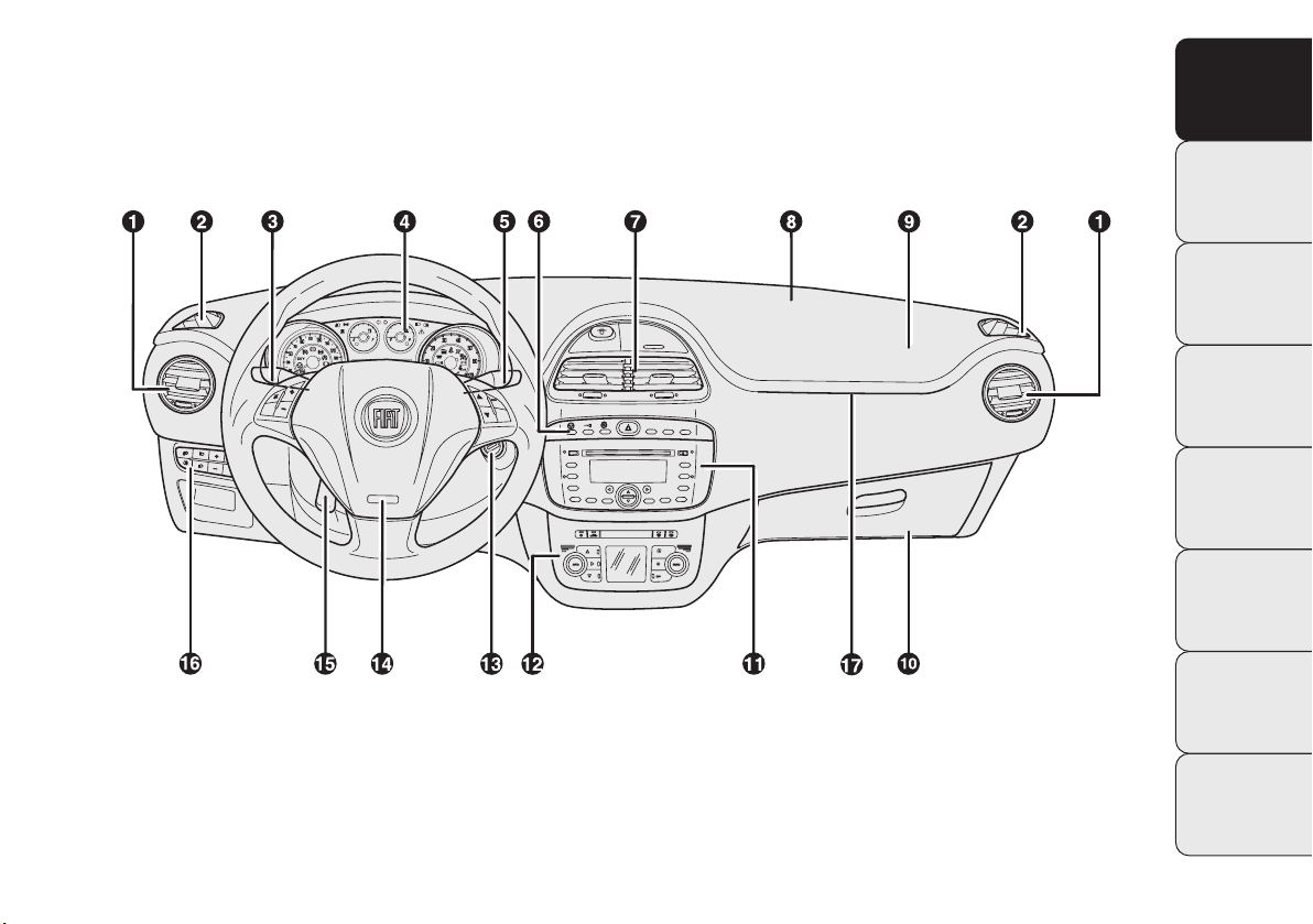
fig. 1
1. Adjustable side air vents - 2. Fixed side air vents - 3. Left-hand lever: exterior lights control - 4. Instrument panel
- 5. Right-hand lever: front and rear windscreen wiper controls, trip computer - 6. Controls on dashboard - 7. Adjustable
central air vents - 8. Fixed upper air vent - 9. Front airbag, passenger side - 10. Glove compartment - 11. Sound system
(for versions/markets where provided) - 12. HVAC controls - 13. Ignition - 14. Front airbag, driver’s side - 15. Steering
wheel adjustment lever - 16. Control panel: headlight position adjustment/digital display/multifunction display - 17. Lightguiding plate.
F0U0654m
TECHNICAL
SPECIFICATIONS
CONTENTS
5
Page 8

KNOWING
VEHICLE
STARTING
AND DRIVING
WARNING LIGHTS
AND MESSAGES
EMERGENCY
SERVICING
AND CARE
TECHNICAL
SPECIFICATIONS
SYMBOLS
YOUR
Special coloured labels have been attached near or actually on some of the components of your Fiat Punto. These
labels bear symbols that remind you of the precautions
to be taken as regards that particular component.
SAFETY
A plate summarising the symbols used can be found under
the bonnet fig. 2.
IN AN
THE FIAT CODE SYSTEM
This is an electrical engine locking system which increases
protection against an attempted theft of the car. It is automatically activated when the ignition key is extracted.
Each key contains an electronic device which modulates
the signal emitted during ignition by an antenna built into
the ignition device. This signal is the ‘password’ which
changes at each ignition and which the control unit uses
to recognise the key and enable ignition.
OPERATION
Each time the vehicle is started by turning the ignition key
to MAR, the Fiat CODE system control unit sends a recognition code to the engine control unit to deactivate the
immobiliser.
The code is sent only if the Fiat CODE system control unit
has recognised the code transmitted from the key.
Each time the ignition key is turned to STOP, the Fiat
CODE system deactivates the functions of the engine control unit.
If the code is not recognised correctly during ignition, the
warning light comes on in the instrument panel.
Y
CONTENTS
6
fig. 2
F0U0618m
Page 9
In this case turn the key to STOP and then to MAR; if the
lock persists try again with the spare set of keys. Contact
a Fiat Dealership if you still cannot start the engine.
Warning light
❒
If the warning light Yturns on, this means that the
comes on when driving
Y
system is running a self-test (for example for a voltage
drop).
❒
If the warning light Ystays on, contact a Fiat Dealership.
The electronic components inside the key
may be damaged if the key is subjected to
sharp knocks.
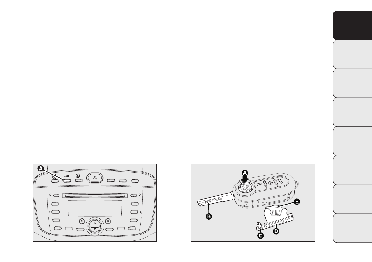
THE KEYS
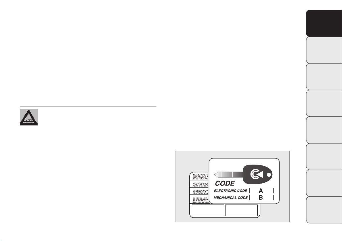
CODE CARD fig. 3
(available on request for versions/markets where provided)
The car is delivered with two copies of the ignition key
and with the CODE card, which bears the following:
A the electronic code;
B the mechanical key code to be given to the Fiat Deal-
ership when ordering duplicate keys.
You should have the electronic code A-fig. 3 with you at
all times.
IMPORTANT In order to ensure complete efficiency of
the electronic devices inside the keys, they should never
be exposed to direct sunlight.
KNOWING
YOUR
VEHICLE
SAFETY
STARTING
AND DRIVING
WARNING LIGHTS
AND MESSAGES
IN AN
EMERGENCY
SERVICING
AND CARE
TECHNICAL
SPECIFICATIONS
fig. 3
CONTENTS
F0U0003m
7
Page 10
KNOWING
YOUR
VEHICLE
SAFETY
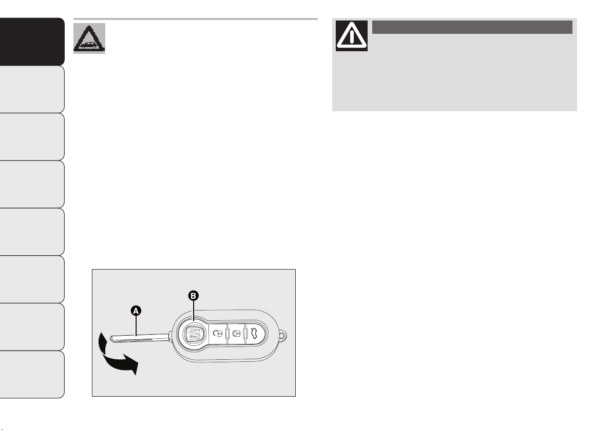
KEY WITH REMOTE CONTROL fig. 4
ST
ARTING
AND DRIVING
WARNING LIGHTS
AND MESSAGES
The metal insert A operates:
❒
the ignition;
❒
the door locks;
❒
the fuel cap lock/release (for versions/markets where
provided);
Pressing button B opens/closes the metal insert.
IN AN
EMERGENCY
SERVICING
AND CARE
TECHNICAL
SPECIFICATIONS
All the keys and the CODE card must be
handed over to the new owner when selling
the car.
WARNING
Only press button B with the key away
from your body, specifically from your
eyes and from objects which could get damaged
(e.g. your clothes). Do not leave the key unattended to avoid the button being accidentally
pressed while it is being handled, e.g. by a child.
Button Ëis used for unlocking the doors and the boot.
Button Á is used for locking the doors and the boot.
Button
R
is used to open the boot remotely.
When unlocking the doors, the passenger compartment
ceiling lights will come on for a preset time.
CONTENTS
8
fig. 4
F0U0004m
Page 11
ASR
OFF
Dashboard LED indications
When locking the doors, the LED A-fig. 5 in the button
switches on for about 3 seconds and then starts to flash
(as a deterrent).
Once doors are locked, if one or more doors or the boot
are not closed correctly, the LED and direction indicators
start flashing quickly.
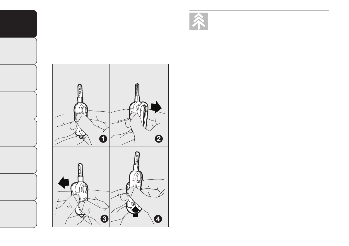
Replacing the battery of the key with remote
control fig. 6
To replace the battery, proceed as follows:
❒
press button A and bring the metal insert B to the open
position;
❒
turn the screw C to :using a fine screwdriver;
❒
take out the battery case D and replace the battery E,
respecting its polarity;
❒
refit the battery case D inside the key and lock it by
turning the screw C to Á.
KNOWING
YOUR
VEHICLE
SAFETY
ST
ARTING
AND DRIVING
WARNING LIGHTS
AND MESSAGES
IN AN
EMERGENCY
SERVICING
AND CARE
TECHNICAL
SPECIFICATIONS
fig. 5
F0U0005m
fig. 6
CONTENTS
F0U0006m
9
Page 12
KNOWING
VEHICLE
REPLACING THE REMOTE CONTROL COVER
fig. 7
YOUR
To replace the remote control cover, follow the procedure shown in the diagram.
SAFETY
STARTING
AND DRIVING
WARNING LIGHTS
AND MESSAGES
IN AN
EMERGENCY
SERVICING
AND CARE
TECHNICAL
SPECIFICATIONS
Used batteries are harmful to the environment. You can dispose of them either in the
correct containers as specified by law or by
taking them to a Fiat Dealership, which will deal
with their disposal.
Requesting additional remote controls
The system acknowledges up to 8 remote controls. Should
a new remote control be necessary, contact a Fiat Dealership, taking with you the CODE card, a personal identity document and the car’s ownership documents.
CONTENTS
10
fig. 7
F0U0007m
Page 13
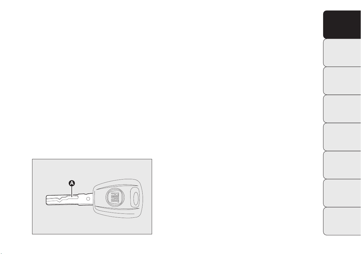
KEY WITHOUT REMOTE CONTROL fig. 8
The metal insert A of the key is fixed.
The key operates:
❒
the ignition;
❒
the door locks;
❒
the fuel tank cap lock (for versions/markets where provided).
ALARM
The car’s alarm system is available from Lineaccessori Fiat.
KNOWING
YOUR
VEHICLE
SAFETY
ST
ARTING
AND DRIVING
WARNING LIGHTS
AND MESSAGES
IN AN
EMERGENCY
SERVICING
AND CARE
TECHNICAL
SPECIFICATIONS
fig. 8
CONTENTS
F0U0008m
11
Page 14

KNOWING
VEHICLE
ST
ARTING
The main functions that can be activated with the keys (with or without remote control) are the following:
YOUR
Type of key
Key without remote control
SAFETY
AND DRIVING
Key with remote control
WARNING LIGHTS
AND MESSAGES
Direction
IN AN
EMERGENCY
indicators flashing (only for
key with remote control)
Deterrence LED
SERVICING
AND CARE
Unlocking
the doors
Turn key
anticlockwise
(driver’s side)
Turn key
anticlockwise
(driver’s side)
Press briefly
button Ë
blinks twice
Off
Door locking
from the outside
Turn key
clockwise
(driver’s side)
Turn key
clockwise
(driver’s side)
Press briefly
Á
button
blinks once
Lit for about
3 seconds followed
by deterrence LED
flashing
Activating
Dead Lock
(where provided)
–
–
Press twice
Á
button
blinks three times
Double flash,
followed by
deterrence
flashing
Unlocking
the boot
–
–
Press briefly
R
button
blinks twice
Deterrence
LED
Windows down
(where provided)
–
–
Hold down
button
Ë
(for more than two
seconds)
blinks twice
Off
Windows up
(where provided)
–
–
Hold down
button
Á
(for more than
two seconds)
blinks once
Deterrence
LED
TECHNICAL
SPECIFICATIONS
CONTENTS
12
IMPORTANT Window opening operation is a consequence of a door unlocking control; window closing operation is
a consequence of a door locking control.
Page 15
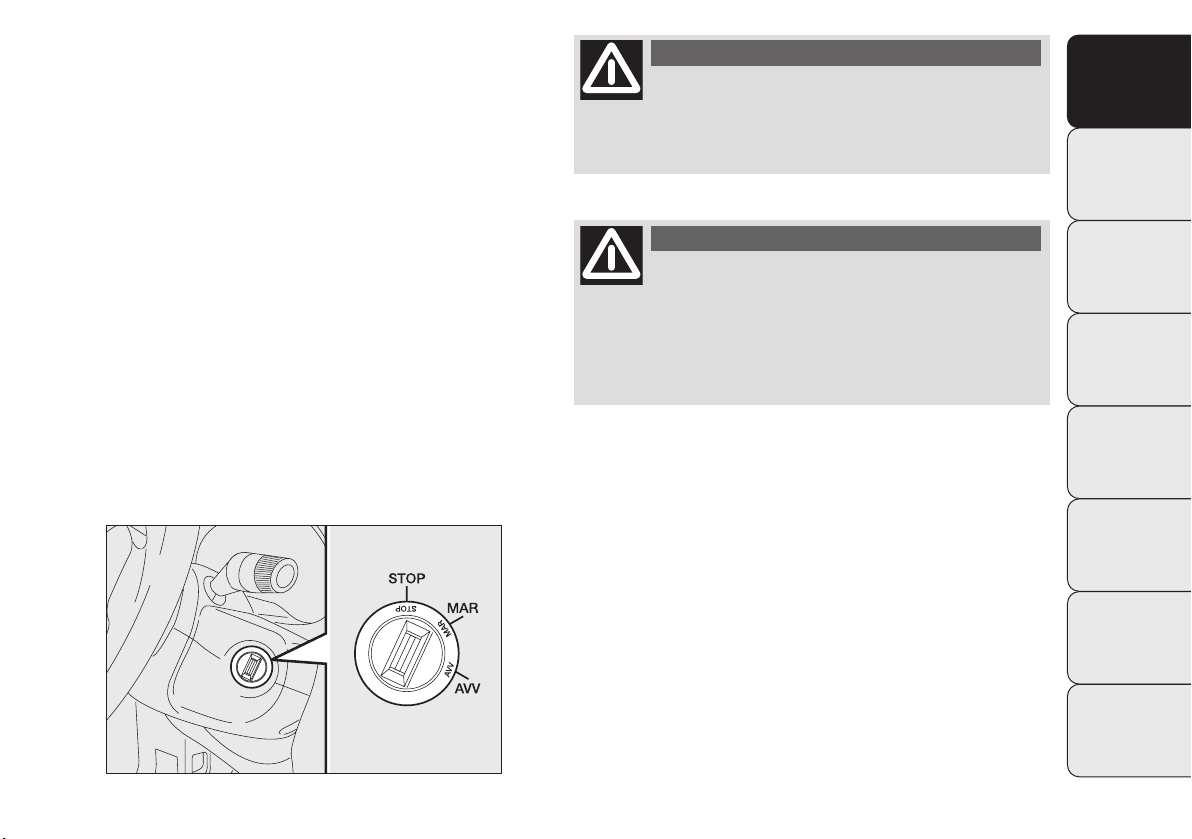
IGNITION
The key can be turned to 3 different positions fig. 9:
❒
STOP: engine off, key can be extracted, steering locked.
Some electrical devices (e.g. sound system, central door
locking system, etc.) can function.
❒
MAR: driving position. All electrical devices can function.
❒
AVV: engine starting (temporary position).
The ignition device is fitted with an electronic safety system that, in the event the engine fails to start, forces you
to turn the ignition key back to STOP before repeating the
starting operation.
WARNING
If the ignition device has been tampered
with (e.g. an attempted theft), have it
checked over by a Fiat Dealership as soon as possible.
WARNING
When getting out of the car, always remove
the key to prevent someone from accidentally activating the controls. Remember to engage
the handbrake. Engage first gear if the car is parked
uphill or reverse if the car is parked downhill. Never leave children unattended in the car.
KNOWING
YOUR
VEHICLE
SAFETY
ST
ARTING
AND DRIVING
WARNING LIGHTS
AND MESSAGES
IN AN
EMERGENCY
SERVICING
AND CARE
TECHNICAL
SPECIFICATIONS
fig. 9
CONTENTS
F0U0655m
13
Page 16
KNOWING
VEHICLE
STARTING
AND DRIVING
WARNING LIGHTS
AND MESSAGES
EMERGENCY
SERVICING
AND CARE
TECHNICAL
SPECIFICATIONS
STEERING LOCK
YOUR
Engagement
When the key is at STOP, remove the key and turn the
steering wheel until it locks.
SAFETY
Disengagement
Move the steering wheel slightly as you turn the ignition
key to MAR.
tomatically as soon as it is turned. This is always
IN AN
the case, even when the vehicle is being towed.
WARNING
It is absolutely forbidden to carry out any
after-sales operation involving steering system or steering column modifications (e.g. installing an anti-theft device) that could badly affect performance and safety, invalidate the warranty and also result in the car failing to comply
with regulations.
WARNING
Never extract the key while the vehicle is
moving. The steering wheel would lock au-
CONTENTS
14
Page 17

INSTRUMENT PANEL
Versions with
multifunction display
A Speedometer
B Fuel level gauge with reserve
warning light
C Engine coolant temperature gauge
with overheating warning light
D Rev counters
E Multifunction display
KNOWING
YOUR
VEHICLE
SAFETY
STARTING
AND DRIVING
WARNING LIGHTS
AND MESSAGES
fig. 11
fig. 12
F0U0660m
IN AN
EMERGENCY
SERVICING
AND CARE
TECHNICAL
SPECIFICATIONS
CONTENTS
F0U0662m
15
Page 18
KNOWING
YOUR
VEHICLE
SAFETY
STARTING
AND DRIVING
WARNING LIGHTS
AND MESSAGES
fig. 13
IN AN
EMERGENCY
SERVICING
AND CARE
TECHNICAL
SPECIFICATIONS
Versions with reconfigurable
multifunction display
(for versions/markets where provided)
A Speedometer
B Fuel level gauge with reserve
warning light
C Engine coolant temperature gauge
with overheating warning light
D Rev counters
E Reconfigurable multifunction dis-
play
F0U0661m
CONTENTS
16
Page 19
INSTRUMENTS
Instrument background colour and type may vary according to the version.
SPEEDOMETER fig. 14
This shows the speed of the vehicle.
REV COUNTER fig. 15
The rev counter shows the number of engine revolutions
per minute.
IMPORTANT The electronic injection control system
gradually shuts off the flow of fuel when the engine is overrevving, resulting in a gradual loss of engine power.
When the engine is idling, the rev counter may indicate a
gradual or sudden increase of the rate.
This is normal and does not indicate a fault. It may be
caused, for example, by the operation of the climate control system or fan. In these cases, a slow change in revs is
used to protect the battery charge.
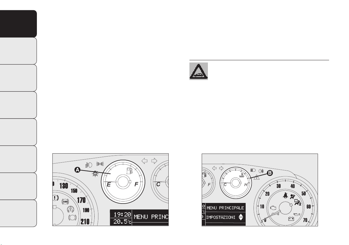
FUEL GAUGE fig. 16
This shows the amount of fuel left in the tank.
E tank empty.
F tank full.
The reserve warning light A comes on to indicate that
approximately 7 litres of fuel are left in the tank.
Do not travel with the fuel tank almost empty: the gaps
in fuel delivery could damage the catalyst.
See the description in the “Refuelling” paragraph.
IMPORTANT The needle will point to E and warning light
A will blink to indicate a fault in the system. If this is the
case, go to a Fiat Dealership to have the system checked.
KNOWING
YOUR
VEHICLE
SAFETY
STARTING
AND DRIVING
WARNING LIGHTS
AND MESSAGES
IN AN
EMERGENCY
SERVICING
AND CARE
TECHNICAL
SPECIFICATIONS
fig. 14
F0U0663m
fig. 15
CONTENTS
F0U0664m
17
Page 20
KNOWING
VEHICLE
ENGINE COOLANT TEMPERATURE
GAUGE fig. 17
YOUR
This shows the temperature of the engine coolant fluid and
starts working when the fluid temperature exceeds approx. 50°C.
SAFETY
Under normal usage, the needle should hover around the
middle of the scale according to the working conditions.
C Low engine coolant temperature.
ST
ARTING
AND DRIVING
H High engine coolant temperature.
WARNING LIGHTS
AND MESSAGES
IN AN
EMERGENCY
SERVICING
AND CARE
TECHNICAL
SPECIFICATIONS
Warning light B may light up (and a message on the multifunction display may appear on certain versions) to indicate that the coolant fluid temperature is too high; in this
case, stop the engine and contact a Fiat Dealership.
If the needle reaches the red area, stop the
engine immediately and contact a Fiat
Dealership.
CONTENTS
18
fig. 16
F0U0665m
fig. 17
F0U0666m
Page 21
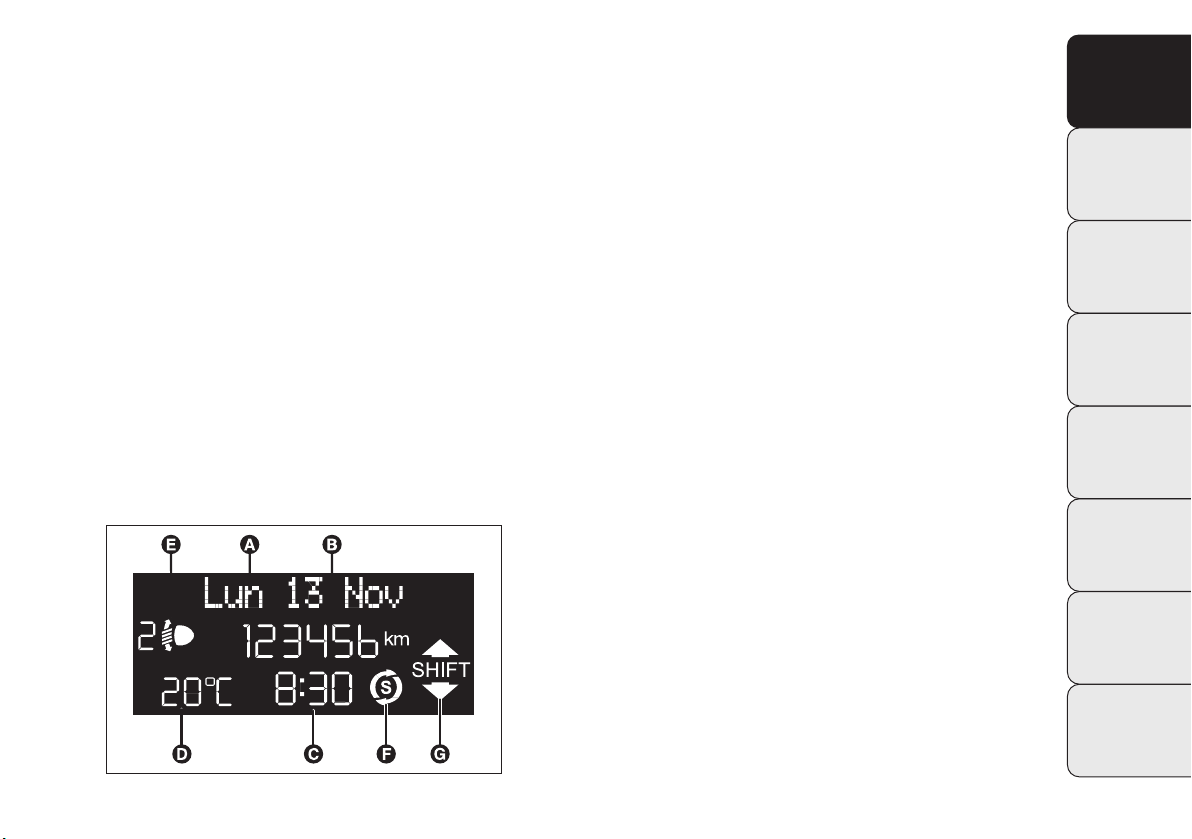
MULTIFUNCTION DISPLAY
(for versions/markets where provided)
The car can be equipped with the multifunction display
that, depending on previous settings, shows useful information when driving.
STANDARD SCREEN fig. 21
The standard screen shows the following information:
A Date.
B Odometer (distance covered in km or miles).
C Time.
D Outside temperature.
E Headlamp alignment position (only with dipped head-
lamps on).
F Start&Stop indicator (for versions/markets where pro-
vided).
G Gear Shift Indicator (for versions/markets where pro-
vided).
NB When one of the front doors is opened, the display
turns on and shows for a few seconds the time and distance covered.
KNOWING
YOUR
VEHICLE
SAFETY
STARTING
AND DRIVING
WARNING LIGHTS
AND MESSAGES
IN AN
EMERGENCY
SERVICING
AND CARE
TECHNICAL
SPECIFICATIONS
fig. 21
CONTENTS
F0U0667m
19
Page 22
KNOWING
VEHICLE
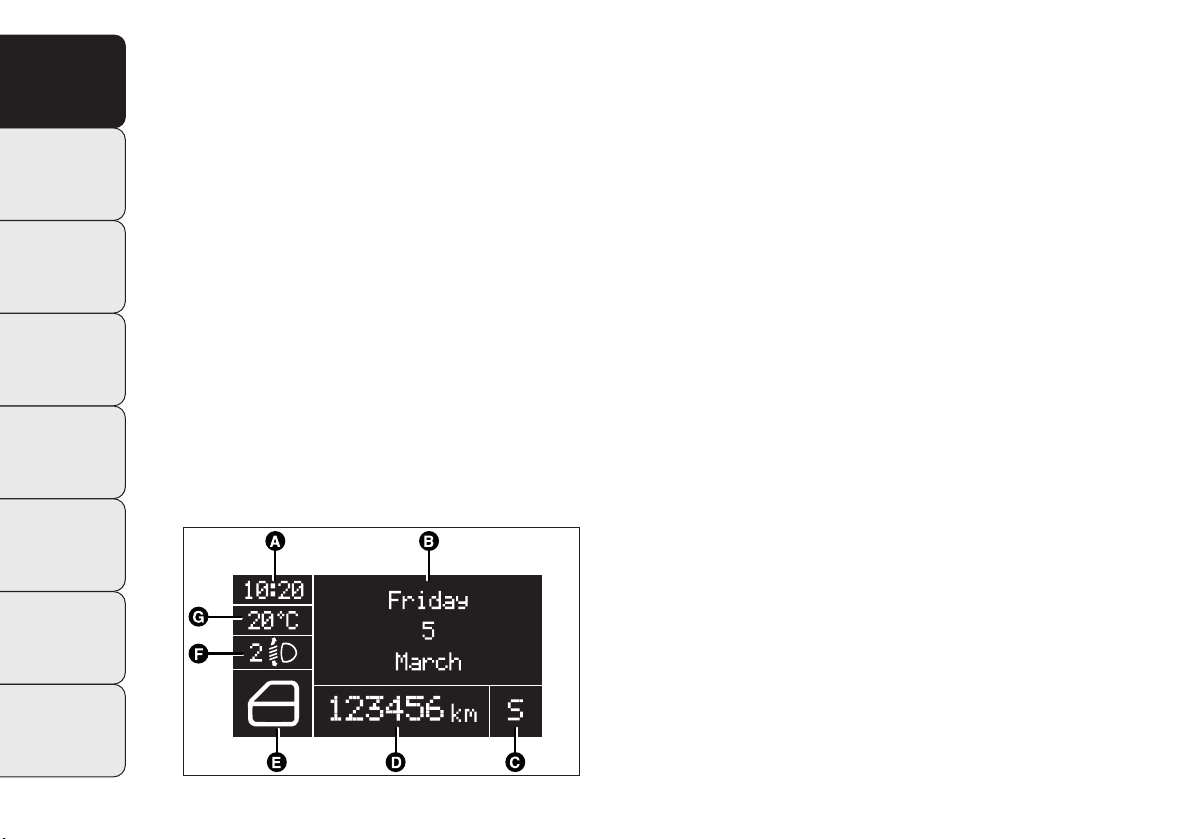
RECONFIGURABLE
MULTIFUNCTION DISPLAY
YOUR
(for versions/markets where provided)
The car may be equipped with a reconfigurable multi-
SAFETY
function display that, according to previous settings, will
show useful driving information.
ST
ARTING
AND DRIVING
STANDARD SCREEN fig. 22
The standard screen shows the following information:
A Time
WARNING LIGHTS
AND MESSAGES
B Date
D Odometer (distance travelled in kilometres/miles)
IN AN
EMERGENCY
SERVICING
AND CARE
TECHNICAL
SPECIFICATIONS
E Car conditions
(e.g. doors open, possible ice on road, etc.)
F Headlamp alignment position
(only with dipped headlamps on).
G Outside temperature
❒
Start&Stop indicator
(for versions/markets where provided)
❒
Gear Shift Indicator
(for versions/markets where provided).
CONTENTS
20
fig. 22
F0U2050g
Page 23
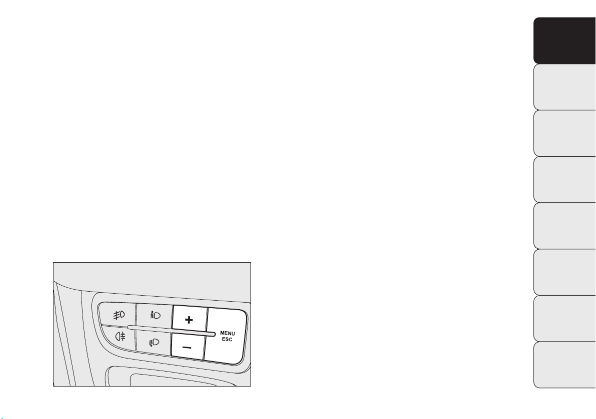
CONTROL BUTTONS MULTIFUNCTION
DISPLAY/RECONFIGURABLE
MULTIFUNCTION DISPLAY fig. 23
+ To scroll the displayed menu and the related op-
tions upwards or to increase the displayed value.
MENU Press briefly to access the menu and/or
ESC
go to the next screen or confirm your choice.
Hold down to go back to the standard screen.
– To scroll the displayed menu and the related options
downwards or to decrease the displayed value.
NB Buttons + and – activate different functions according to the following situations:
Adjusting the car’s interior lighting
– on the standard screen, they control instrument panel
brightness, the sound system and the automatic climate
control system.
Setup menu
– within the menu, they scroll up and down;
– during setting operations they allow an increase or decrease in value.
KNOWING
YOUR
VEHICLE
SAFETY
ST
ARTING
AND DRIVING
WARNING LIGHTS
AND MESSAGES
IN AN
EMERGENCY
SERVICING
AND CARE
fig. 23
TECHNICAL
SPECIFICATIONS
CONTENTS
F0U0019m
21
Page 24

KNOWING
VEHICLE
STARTING
AND DRIVING
WARNING LIGHTS
AND MESSAGES
EMERGENCY
SERVICING
AND CARE
TECHNICAL
SPECIFICATIONS
SETUP MENU
(multifunction display/
YOUR
reconfigurable multifunction display)
The menu comprises a series of functions arranged in a
SAFETY
circle which can be selected through the + and – buttons
to access the different operations and settings described
in the following paragraphs. A submenu is provided for
some items (clock and unit setting).
The setup menu can be activated by pressing the MENU
ESC button briefly.
Press buttons + and – to scroll the setup menu options.
Management modes differ from each other according to
the option selected.
Selecting an option from the main menu without a submenu
IN AN
– Briefly press MENU ESC to select the main menu option
you wish to set;
– Press + or – (with single presses) to select the new set-
ting;
– briefly press the MENU ESC button to store the new
setting and to go back to the main menu option selected
previously.
Selecting an option from the main menu with a submenu:
– Briefly press the MENU ESC button to display the first
submenu option;
– Press + or – (with single presses) to scroll all the submenu options;
– Briefly press the MENU ESC button to select the displayed submenu option and to open the relevant setup
menu;
– Press + or – (with single presses) to select the new set-
ting for this submenu option;
– Briefly press the MENU ESC button to store the new
setting and go back to the previous menu option.
Selecting “Date” and “Set time”:
– Briefly press MENU ESC to select the first value to
change (e.g. hours/minutes or year/month/day);
– Press + or – (with single presses) to select the new set-
ting;
– Briefly press MENU ESC to store the new setting and
go to the next setup menu option; if this is the last one
you will go back to the previous menu option.
CONTENTS
22
Page 25

Hold down the MENU ESC button:
– to quit the setup menu if you are in the main menu;
– to quit the main menu if you are in another point of the
menu (e.g. at submenu option setting level, at submenu level or at main menu option setting level);
– to save only the settings already stored (and confirmed
by pressing the MENU ESC button).
The setup menu environment is timed. Only the changes
saved by the user (having been confirmed by briefly pressing MENU ESC) will be stored when the menu is automatically closed.
The menu consists of the following items:
– MENU
– SPEED BEEP
– CORNER LIGHTS
(for versions/markets where provided)
– RAIN SENSOR
(for versions/markets where provided)
– TRIP B ACTIVATION/DATA
– SET TIME
– SET DATE
– FIRST PAGE (for versions/markets where provided)
– SEE RADIO
– AUTOCLOSE
– UNITS OF MEASUREMENT
– LANGUAGE
– WARNING VOLUME
– BUTTON VOLUME
– SEAT BELT BEEP/BUZZ
– SERVICE
– AIRBAG/PASSENGER BAG
– DAYTIME RUNNING LIGHTS
– EXIT MENU
KNOWING
YOUR
VEHICLE
SAFETY
STARTING
AND DRIVING
WARNING LIGHTS
AND MESSAGES
IN AN
EMERGENCY
SERVICING
AND CARE
TECHNICAL
SPECIFICATIONS
CONTENTS
fig. 27
F0U0019m
23
Page 26

KNOWING
VEHICLE
DISPLAY FUNCTIONS
(see multifunction display
YOUR
or reconfigurable multifunction
display)
SAFETY
SPEED BEEP
(Setting the speed limit)
STARTING
AND DRIVING
WARNING LIGHTS
AND MESSAGES
EMERGENCY
SERVICING
AND CARE
TECHNICAL
SPECIFICATIONS
This function is used to set the car speed limit (km/h or
mph); the driver is immediately alerted when this limit is
exceeded (see section “Warning lights and messages”).
To set the desired speed limit, proceed as follows:
– briefly press the MENU ESC button: the display will show
the words (Speed Beep);
– press + or – to select speed limit activation (On) or
deactivation (Off);
IN AN
– when the function has been activated (On) by pressing
buttons + or –, select the speed limit and press MENU
ESC to confirm selection.
NB You can select a speed between 30 and 200 km/h,
or 20 and 125 mph depending on the selected unit, see
“Setting measurement unit (Unit)”. The setting will increase/decrease by five units each time + / – is pressed.
Hold down +/– to increase/decrease the setting rapidly.
Complete the setting with single presses of the button
when you approach the required setting.
– briefly press the MENU ESC button to go back to the
menu screen or hold the button down to go back to the
standard screen without saving.
To cancel the setting, proceed as follows:
– press the MENU ESC button briefly to make the display flash (On);
– press –: (Off) will flash on the display;
– briefly press the MENU ESC button to go back to the
menu screen or hold the button down to go back to the
standard screen without saving.
CONTENTS
24
Page 27

CORNER LIGHTS
(activation/deactivation of corner lights – fog
lights with cornering function)
(for versions/markets where provided)
This function activates/deactivates the corner lights. To activate/deactivate (ON/OFF) the lights, proceed as follows:
– press the MENU ESC button briefly: the display will show
“On” or “Off” flashing depending on the previous setting;
– press + or – to make your choice;
– briefly press the MENU ESC button to go back to the
menu screen or hold the button down to go back to the
standard screen without saving.
RAIN SENSOR
(Adjusting sensitivity)
(for versions/markets where provided)
This function allows you to adjust the rain sensor sensitivity over 4 levels.
To set the required sensitivity level, proceed as follows:
– briefly press MENU ESC: the previously set sensitivity
level will flash on the display;
– press + or – to set the value;
– briefly press the MENU ESC button to go back to the
menu screen or hold the button down to go back to the
standard screen without saving.
KNOWING
YOUR
VEHICLE
SAFETY
STARTING
AND DRIVING
WARNING LIGHTS
AND MESSAGES
IN AN
EMERGENCY
SERVICING
AND CARE
TECHNICAL
SPECIFICATIONS
CONTENTS
25
Page 28

KNOWING
VEHICLE
ST
ARTING
AND DRIVING
WARNING LIGHTS
AND MESSAGES
EMERGENCY
SERVICING
AND CARE
TECHNICAL
SPECIFICATIONS
TRIP B ACTIVATION/DATA
(Trip B enablement)
YOUR
This function may be used to activate (On) or deactivate
(Off) the Trip B display (partial trip).
For more information see the “Trip computer” section.
SAFETY
For activation/deactivation, proceed as follows:
– briefly press MENU ESC: On or Off will flash on the dis-
play (depending on previous setting);
– press + or – to make your choice;
– briefly press the MENU ESC button to go back to the
menu screen or hold the button down to go back to the
standard screen without saving.
IN AN
SET TIME
(Setting the clock)
This function allows you to set the clock through two submenus: “Time” and “Mode”.
To carry out the adjustment, proceed as follows:
– briefly press MENU ESC: the display will show the two
submenus “Time” and “Mode”;
– press + or – to switch between the two sub-menus;
– once you have selected a submenu, press MENU ESC
briefly;
– if selecting “Time”, briefly press MENU ESC – the “hours”
will flash on the display;
– press + or – to set the value;
– briefly press MENU ESC: the “minutes” will flash on the
display;
– press + or – to set the value;
– if selecting “Mode”, briefly press MENU ESC: the mode
will flash on the display;
– press + or – to select “24h” or “12h”.
CONTENTS
26
Page 29

When you have made the required adjustments, briefly
press button MENU ESC to go back to the submenu
screen or hold the button down to go back to the main
menu screen without saving.
– hold down MENU ESC again to go back to the standard
screen or main menu, depending on which point in the
menu you have reached.
Set date
(Setting the date)
Using this function it is possible to change the date (day –
month – year).
To update, proceed as follows:
– briefly press MENU ESC: the day (dd) will flash on the
display;
– press + or – to set the value;
– briefly press MENU ESC: the month (mm) will flash on
the display;
– press + or – to set the value;
– briefly press MENU ESC: the year (yyyy) will flash on the
display;
– press the+ oppure – button to make the adjustment.
NB Each time the + or – buttons are pressed there is an
increase or decrease of one unit. Hold the button down
to increase/decrease the setting rapidly. Complete the setting with single presses of the button when you approach
the required setting.
– briefly press the MENU ESC button to go back to the
menu screen or hold the button down to go back to the
standard screen without saving.
FIRST PAGE
(information displayed on the main screen)
(for versions/markets where available)
This function allows you to choose the information you
would like to see on the main screen. You can choose
to display the date or the turbocharger boost pressure.
To make your choice, proceed as follows:
– briefly press MENU ESC: “First page” will appear on
the display;
– briefly press MENU ESC again to show the display options: “Date” and “Engine info”;
– press + or – to select the information you wish to see
on the main page of the display;
KNOWING
YOUR
VEHICLE
SAFETY
ST
ARTING
AND DRIVING
WARNING LIGHTS
AND MESSAGES
IN AN
EMERGENCY
SERVICING
AND CARE
TECHNICAL
SPECIFICATIONS
CONTENTS
27
Page 30

KNOWING
VEHICLE
ST
ARTING
AND DRIVING
WARNING LIGHTS
AND MESSAGES
EMERGENCY
SERVICING
AND CARE
TECHNICAL
SPECIFICATIONS
– briefly press the MENU ESC button to go back to the
menu screen or hold the button down to go back to the
YOUR
standard screen without saving.
When the key is turned to MAR and the initial check stage
is over, the display will show the information selected via
the “First page” menu function.
SAFETY
SEE RADIO
(Relaying audio information)
With this function the display shows information relevant
to the sound system.
– Radio: selected radio station frequency or RDS message,
automatic tuning activation or AutoSTore;
– CD, MP3: track number;
– CD Changer: CD number and track number;
IN AN
To show the sound system information in the display (On)
or clear it (Off), proceed as follows:
– briefly press MENU ESC: On or Off will flash on the display (depending on previous setting);
– press + or – to make your choice;
– briefly press the MENU ESC button to go back to the
menu screen or hold the button down to go back to the
standard screen without saving.
AUTOCLOSE
(Automatic central locking with car moving)
When activated (On), this function automatically locks the
doors when the car speed exceeds 20 km/h.
To activate (On) or deactivate (Off) this function, proceed
as follows:
– press the MENU ESC button briefly: the display will show
a submenu;
– briefly press MENU ESC: On or Off will flash on the display (depending on previous setting);
– press + or – to make your choice;
– briefly press the MENU ESC button to go back to the
submenu screen or hold the button down to go back to
the main menu screen without saving;
– hold down MENU ESC again to go back to the standard
screen or main menu, depending on which point in the
menu you have reached.
CONTENTS
28
Page 31

MEASUREMENT UNITS
(Setting measurement units)
With this function it is possible to set the measurement
units through three sub-menus: “Distance”, “Consumption” and “Temperature”.
To set the desired measurement unit, proceed as follows:
– briefly press MENU ESC to display the three submenus;
– press + or – to switch between the three sub-menus;
– once the submenu to be modified has been selected, briefly
press the MENU ESC button;
– if selecting “Distance”: briefly press MENU ESC and the
display will show “km” or “mi” (depending on the previous setting);
– press + or – to make your choice;
– if selecting “Consumption”: briefly press MENU ESC and
the display will show “km/l”, “l/100km” or “mpg” (depending on the previous setting);
If the set distance unit is “km”, you can set the fuel consumption unit to km/l or l/100km depending on the
amount of fuel consumed.
If the distance unit set is “mi” the fuel consumption unit
will be displayed in “mpg”.
– press + or – to make your choice;
– if selecting “Temperature”: briefly press MENU ESC and
the display will show “°C” or “°F” (depending on the previous setting);
– press + or – to make your choice.
When you have made the required adjustments, briefly
press MENU ESC to go back to the submenu screen or
hold the button down to go back to the main menu screen
without saving.
– hold down MENU ESC again to go back to the standard
screen or main menu, depending on which point in the
menu you have reached.
KNOWING
YOUR
VEHICLE
SAFETY
ST
ARTING
AND DRIVING
WARNING LIGHTS
AND MESSAGES
IN AN
EMERGENCY
SERVICING
AND CARE
TECHNICAL
SPECIFICATIONS
CONTENTS
29
Page 32

KNOWING
VEHICLE
ST
ARTING
AND DRIVING
WARNING LIGHTS
AND MESSAGES
EMERGENCY
SERVICING
AND CARE
TECHNICAL
SPECIFICATIONS
LANGUAGE
(Selecting language)
YOUR
Display messages can be shown in different languages: Italian, German, English, Spanish, French, Portuguese, Polish,
Dutch and Turkish.
SAFETY
To set the required language, proceed as follows:
– briefly press MENU ESC: the previously set language will
flash on the display;
– press + or – to make your choice;
– briefly press the MENU ESC button to go back to the
menu screen or hold the button down to go back to the
standard screen without saving.
IN AN
WARNING VOLUME
(Adjusting the failure/warning buzzer volume)
This function allows the volume of the buzzer which accompanies the display of failures/warnings to be adjusted
(over 8 levels).
To set the desired volume, proceed as follows:
– briefly press MENU ESC: the previously set volume level will flash on the display;
– press + or – to set the value;
– briefly press the MENU ESC button to go back to the
menu screen or hold the button down to go back to the
standard screen without saving.
CONTENTS
30
Page 33

BUTTON VOLUME
(Adjusting the button volume)
This function may be used to adjust (over 8 levels) the volume of the noise made when the MENU ESC, + e – but-
tons are pressed.
To set the desired volume, proceed as follows:
– briefly press MENU ESC: the previously set volume level will flash on the display;
– press + or – to set the value;
– briefly press the MENU ESC button to go back to the
menu screen or hold the button down to go back to the
standard screen without saving.
SEAT BELT BUZZ
(SBR buzzer reactivation
(for versions/markets where provided)
This function can be displayed only after a Fiat Dealership has deactivated the SBR system (see “SBR system”
in the “Safety” section).
SERVICE
(Scheduled servicing)
Through this function it is possible to display information
related to regular scheduling intervals.
This information can be consulted as follows:
– briefly press MENU ESC: service intervals in km or mi,
depending on the previous setting, will be displayed (see
“Measurement units”);
– press the MENU ESC button briefly to return to the
menu screen or hold the button down to return to the
standard screen.
NB The “Scheduled Servicing Plan” requires the vehicle
to be serviced every 30,000 km (or 18,000 mi) for petrol
Euro 4 / Euro 5 and Diesel Euro 4 versions and every
35,000 km (or 21,000 mi) for Diesel Euro 5 versions.
This indication will appear automatically, with the key at
MAR, starting from 2,000 km (or 1,240 mi) and will be displayed every 200 km (or 124 mi).
Below 200 km the signals become more frequent. The indication will appear in kilometres or miles depending on
the unit of measurement settings. When the next scheduled service is approaching, the message “Service” will appear on the display, followed by the number of kilometres
or miles left, when the key is turned to MAR. Go to a Fiat Dealership, where the “Scheduled Servicing Plan” operations will be performed and the message will be reset.
KNOWING
YOUR
VEHICLE
SAFETY
ST
ARTING
AND DRIVING
WARNING LIGHTS
AND MESSAGES
IN AN
EMERGENCY
SERVICING
AND CARE
TECHNICAL
SPECIFICATIONS
CONTENTS
31
Page 34

KNOWING
VEHICLE
ST
ARTING
AND DRIVING
WARNING LIGHTS
AND MESSAGES
EMERGENCY
SERVICING
AND CARE
TECHNICAL
SPECIFICATIONS
AIRBAG/PASSENGER BAG
(Passenger front and side airbag
YOUR
activation/deactivation)
(side-bag for versions/markets where available)
This function is used to activate/deactivate the front passenger’s air bag.
SAFETY
Proceed as follows:
❒
press MENU ESC and, after the message BAG P Off (to
deactivate) or BAG P On (to activate) is displayed by
pressing buttons + or –, press MENU ESC again;
❒
the display will show the confirmation request message;
❒
press + or – to select either Yes (to confirm activation/deactivation) or No (to abort);
❒
briefly press MENU ESC to confirm setting and go back
IN AN
to the menu screen or hold the button down to go back
to the standard screen without saving.
DAYTIME RUNNING LIGHTS (D.R.L.)
(for versions/markets where provided)
This function allows you to activate/deactivate the daytime
running lights.
Proceed as follows to switch this function on or off:
– press the MENU ESC button briefly: the display will show
a submenu;
– press the MENU ESC button briefly, the display will show
On or Off flashing depending on the previous setting;
– press + or – to change the setting;
– briefly press the MENU ESC button to go back to the
submenu screen or hold the button down to go back to
the main menu screen without saving;
– hold down MENU ESC again to go back to the standard
screen or main menu, depending on which point in the
menu you have reached.
EXIT MENU
This function closes the cycle of settings listed in the menu
screen.
Briefly press MENU ESC to go back to the standard screen
without saving.
Press – to return to the first menu option (Speed Beep).
CONTENTS
32
Page 35

TRIP COMPUTER
Introduction
The Trip computer is used to display information on car
operation when the key is turned to MAR. This function
allows you to define two separate trips, called “Trip A”
and “Trip B”, for monitoring the car’s “complete mission”
(journey) in a reciprocally independent manner.
Both functions can be reset (reset – start of a new journey).
“Trip A” is used to display the figures relating to:
– Outside temperature
– Range
– Distance travelled
– Average consumption
– Current consumption
– Average speed
– Journey time (driving time).
“Trip B”, available on multifunction display only, is used to
display the figures relating to:
– Distance travelled B
– Average consumption B
– Average speed B
– Travel time B (driving time).
NB “Trip B” functions may be excluded (see “Trip B on”).
“Range” and “Instant consumption” parameters cannot be
reset.
Values displayed
Outside temperature
Indicates the temperature outside the vehicle passenger
compartment.
Range
This indicates the approximate distance that may be travelled with the fuel remaining in the tank, assuming that driving conditions do not change. The display will show the
reading “----” when the following events take place:
– value lower than 50 km (or 30 mi)
– car left parked with engine running for a long time.
Distance travelled
This value shows the distance covered from the start of
the new journey.
Average consumption
This value shows the approximate average fuel consumption from the start of the new journey.
Current consumption
Indicates the fuel consumption. The value is constantly updated. The message “----” will appear on the display if the
car is parked with the engine running.
Average speed
This value shows the car’s average speed based on the
overall time elapsed since the start of the new journey.
KNOWING
YOUR
VEHICLE
SAFETY
ST
ARTING
AND DRIVING
WARNING LIGHTS
AND MESSAGES
IN AN
EMERGENCY
SERVICING
AND CARE
TECHNICAL
SPECIFICATIONS
CONTENTS
33
Page 36

KNOWING
VEHICLE
Journey time
This value shows the time elapsed since the start of the
YOUR
new journey.
IMPORTANT If information is not available, the message
“----” will appear instead of the Trip Computer values.
SAFETY
Counting of the different values will resume regularly when
normal operation is restored. This will not reset any of the
values displayed before the failure nor start a new jour-
ST
ARTING
AND DRIVING
ney.
TRIP control button fig. 28
The TRIP button, located on the top of the right steering
WARNING LIGHTS
AND MESSAGES
column stalk, is used (with ignition at MAR) to display and
reset the previous values to start a new journey:
– press briefly to display the different values;
– hold down to reset and then start a new journey.
IN AN
EMERGENCY
SERVICING
AND CARE
TECHNICAL
SPECIFICATIONS
New journey
The new journey begins after:
– “manual” resetting by the user, by pressing the relevant
button;
– “automatic” resetting, when the distance travelled reaches 99,999.9 km or when the journey time reaches 99.59
(99 hours and 59 minutes);
– disconnection and subsequent reconnection of the battery.
IMPORTANT The reset operation when “Trip A” details
are being displayed resets only the information associated with this function.
IMPORTANT The reset operation when “Trip B” details
are being displayed resets only the information associated with this function.
Start trip procedure
With the ignition key in the MAR position, reset by pressing the TRIP button and keeping it pressed for more than
2 seconds.
Trip Exit
To quit the Trip function: keep MENU ESC pressed for
over 2 seconds.
CONTENTS
34
fig. 28
F0U0656m
Page 37

FRONTSEATS
Any adjustments should be carried out only when the vehicle is stationary.
WARNING
WARNING
After releasing the adjustment lever, al-
ways check that the seat is locked on the
guides by trying to move it back and forth. If it is
not locked, the seat may move unexpectedly and
make you lose control of the car.
KNOWING
YOUR
VEHICLE
SAFETY
The fabric covers on your vehicle have been
designed to resist normal wear and tear.
Some precautions are however needed.
Avoid prolonged rubbing against clothing accessories, such as metal buckles, bosses, Velcro strips
and the like, which by applying a high pressure on
the fabric in a small area could cause the breakage of some threads and damage the upholstery.
Horiziontal adjustment fig. 29
Lift the lever A and push the seat forwards or backwards:
in the driving position your arms should rest on the rim
of the steering wheel.
Height adjustment fig. 29
(for versions/markets where provided)
Move lever B upwards or downwards to achieve the required height.
IMPORTANT Adjustment must be carried out only when
seated in the relevant seat.
Backrest angle adjustment fig. 29
Turn knob C.
fig. 29
F0U0023m
ST
ARTING
AND DRIVING
WARNING LIGHTS
AND MESSAGES
IN AN
EMERGENCY
SERVICING
AND CARE
TECHNICAL
SPECIFICATIONS
CONTENTS
35
Page 38

KNOWING
YOUR
VEHICLE
make sure the seat belt fits closely across your
chest and hips.
SAFETY
WARNING
For maximum protection, keep the back
of your seat upright, lean back into it and
WARNING
Always check that the seat is properly
locked on the guides by trying to push it
backwards and forwards.
Folding down the backrest (3-door versions)
ST
ARTING
AND DRIVING
fig. 30
To access the rear seats, pull handle A upwards: the back-
rest will fold forwards and the seat will slide forwards when
you push the backrest.
WARNING LIGHTS
AND MESSAGES
When you put the backrest back up, the seat will return
to its original position (mechanical memory).
IN AN
EMERGENCY
SERVICING
AND CARE
TECHNICAL
SPECIFICATIONS
CONTENTS
36
fig. 30
F0U0024m
Electric lumbar support adjustment fig. 31
(for versions/markets where available)
To adjust the support for your back, use controls E.
fig. 31
F0U0025m
Page 39

Heated seats fig. 32
(for versions/markets where available)
With the key turned to MAR, press button F to switch the
function on/off. When the function is enabled, the LED on
the button turns on.
REAR SEATS
To fold the rear seats, refer to the “Extending the boot”
paragraph in this section.
The fabric upholstery of your car is designed
to withstand normal wear and tear for
a long time. Some precautions are however needed. Avoid prolonged rubbing against clothing accessories, such as metal buckles, bosses,
Velcro strips and the like, which by applying a high
pressure on the fabric in a small area could cause
the breakage of some threads and damage the upholstery.
KNOWING
YOUR
VEHICLE
SAFETY
ST
ARTING
AND DRIVING
WARNING LIGHTS
AND MESSAGES
IN AN
EMERGENCY
SERVICING
AND CARE
TECHNICAL
SPECIFICATIONS
fig. 32
CONTENTS
F0U0026m
37
Page 40

KNOWING
HEAD RESTRAINTS
YOUR
VEHICLE
FRONT HEAD RESTRAINTS fig. 33
On certain versions the head restraints are adjustable in
height and they lock automatically in the required position.
SAFETY
To adjust head restraints, proceed as follows:
❒ upwards adjustment: lift the head restraint until it locks.
ST
ARTING
AND DRIVING
❒ downwards adjustment: press the button A and lower
the head restraint.
To extract the front head restraints press buttons A and
WARNING LIGHTS
B simultaneously and release them upwards.
AND MESSAGES
IN AN
EMERGENCY
SERVICING
AND CARE
TECHNICAL
SPECIFICATIONS
To make the best use of the head restraint protection, ad-
just the backrest to keep a straight back, with the head
as close as possible to its restraint.
WARNING
Head restraints must be adjusted so that
the head, rather than the neck, rests on
them. Only then can they protect your head correctly.
CONTENTS
38
fig. 33
F0U0027m
Page 41

REAR HEAD RESTRAINTS fig. 34
(for versions/markets where provided)
To move the head restraint upwards, raise it until hearing the click (position of use).
To bring it back to the position of non-use, press button
A and push the head restraint down into the back rest.
To extract the rear head restraints press buttons A and
B simultaneously and release them upwards.
IMPORTANT When the rear seats are in use, the head
restraints must always be in the position of use.
STEERING WHEEL
The driver can adjust the height and axial position of the
steering wheel.
To carry out the adjustment, proceed as follows:
❒ release lever A-fig. 35 by pushing it forwards (position 1);
❒ adjust the steering wheel;
❒ lock lever A by pulling it towards the steering wheel (po-
sition 2).
KNOWING
YOUR
VEHICLE
SAFETY
ST
ARTING
AND DRIVING
fig. 34
F0U0028m
WARNING
Any adjustment of the steering wheel position must be carried out only with the car
stationary and the engine turned off.
fig. 35
WARNING LIGHTS
AND MESSAGES
IN AN
EMERGENCY
SERVICING
AND CARE
TECHNICAL
SPECIFICATIONS
CONTENTS
F0U0652m
39
Page 42

KNOWING
YOUR
VEHICLE
system or steering column modifications (e.g. installing an anti-theft device) that could badly af-
SAFETY
fect performance and safety, invalidate the warranty and also result in the car failing to comply
with regulations.
ST
ARTING
AND DRIVING
WARNING LIGHTS
AND MESSAGES
IN AN
EMERGENCY
SERVICING
AND CARE
TECHNICAL
SPECIFICATIONS
WARNING
It is absolutely forbidden to carry out any
after-market operation involving steering
MIRRORS
REAR-VIEW MIRROR fig. 36
The mirror is fitted with a safety device that causes its release in the event of a violent impact with the passenger.
Lever A can be used to move the mirror to two different
positions: normal or antiglare.
CONTENTS
40
fig. 36
F0U0030m
Page 43

ELECTROCHROMIC REAR-VIEW MIRROR
fig. 37
(for versions/markets where provided)
Some versions have an electrochromic mirror with automatic antiglare function.
When the function is active, LED A on the mirror is lit.
WING MIRRORS
Adjustment fig. 38
This operation is possible only with the key turned to
MAR.
To carry out the adjustment, proceed as follows:
❒ use switch B to select the required mirror (left or right);
❒ to adjust the mirror, move switch C in the four direc-
tions.
KNOWING
YOUR
VEHICLE
SAFETY
ST
ARTING
AND DRIVING
WARNING LIGHTS
AND MESSAGES
IN AN
EMERGENCY
SERVICING
AND CARE
TECHNICAL
SPECIFICATIONS
fig. 37
F0U0342m
fig. 38
CONTENTS
F0U0032m
41
Page 44

KNOWING
VEHICLE
Folding
When required (for example when the shape causes dif-
YOUR
ficulty in narrow spaces), it is possible to fold the mirrors
by moving them from position 1-fig. 39 to position 2.
SAFETY
Defrosting/demisting
(for versions/markets where provided)
The mirrors are fitted with resistors that are activated
when the heated rear windscreen is turned on (by pressing button
(
).
IMPORTANT This function is timed and it will turn off automatically after a few minutes.
ST
ARTING
AND DRIVING
WARNING LIGHTS
AND MESSAGES
IN AN
EMERGENCY
SERVICING
AND CARE
TECHNICAL
SPECIFICATIONS
CONTENTS
42
When driving, the mirrors should always be
in position 1-fig. 39.
fig. 39
WARNING
As the driver’s wing mirror is curved, it may
slightly alter the perception of distance.
F0U0033m
Page 45

HEATING AND VENTILATION SYSTEM
fig. 40
F0U0034m
KNOWING
YOUR
VEHICLE
SAFETY
ST
ARTING
AND DRIVING
WARNING LIGHTS
AND MESSAGES
IN AN
EMERGENCY
SERVICING
AND CARE
TECHNICAL
SPECIFICATIONS
1. Fixed upper vent - 2. Adjustable central vents - 3. Fixed side vents - 4. Adjustable side vents - 5. Lower vents for front
seats - 6. Lower vents for rear seats.
CONTENTS
43
Page 46

KNOWING
VEHICLE
ADJUSTABLE SIDE AND
CENTRE VENTS fig. 41-42-43
YOUR
A Fixed vent for side windows.
B Adjustable side vents.
C Adjustable centre vents.
SAFETY
Vents A are fixed.
To use vents B and C, adjust them as required.
ST
ARTING
AND DRIVING
OPENING/CLOSING THE VENTS
To open/close the air vents, move the wheel fig. 42.
WARNING LIGHTS
AND MESSAGES
ç = vents closed
å = vents open
IN AN
EMERGENCY
SERVICING
AND CARE
TECHNICAL
SPECIFICATIONS
CONTROLS fig. 44
Knob A regulates the air temperature
(mixing hot and cold air)
Red section = hot air
Blue section = cold air
fig. 42
F0U0036m
CONTENTS
44
fig. 41
F0U0035m
fig. 43
F0U0271m
Page 47

Knob B activates/adjusts the fan
p 0 = fan off
1-2-3 = fan speed
4
-
= max. fan speed
Knob C adjusts air distribution
to direct air to the centre and side vents;
to send air to the feet and direct cooler air to the
ß
dashboard vents, in intermediate temperature conditions;
for heating when the outside temperature is very low:
©
to direct as much air as possible to the feet;
to warm the feet and, at the same time, demist the
®
windscreen;
-
for quick windscreen demisting.
Button D turns air recirculation on/off
Press the button (button LED on) to turn the air internal
recirculation on.
Press the button (button LED off) to turn air internal recirculation off.
KNOWING
YOUR
VEHICLE
SAFETY
ST
ARTING
AND DRIVING
WARNING LIGHTS
AND MESSAGES
IN AN
EMERGENCY
SERVICING
AND CARE
TECHNICAL
SPECIFICATIONS
fig. 44
CONTENTS
F0M0037m
45
Page 48

KNOWING
VEHICLE
ST
ARTING
AND DRIVING
WARNING LIGHTS
AND MESSAGES
EMERGENCY
SERVICING
AND CARE
TECHNICAL
SPECIFICATIONS
CONTENTS
PASSENGER COMPARTMENT VENTILATION
To ventilate the passenger compartment properly, pro-
YOUR
ceed as follows:
❒ turn knob A to blue section;
❒ turn air recirculation off by pressing button D (button
SAFETY
IN AN
LED off);
❒ turn knob C to
❒ turn knob B to the required speed.
PASSENGER COMPARTMENT HEATING
Proceed as follows:
❒ turn knob A to red section;
❒ turn knob C to the required position;
❒ turn knob B to the required speed.
RAPID PASSENGER COMPARTMENT
HEATING
For the rapid heating of the passenger compartment, proceed as follows:
❒ turn knob A to red section;
❒ turn air recirculation on by pressing button D (button
LED on);
❒ turn knob C to
❒ rotate knob B to 4
;
;
©
-
(max. fan speed).
Then use the controls to keep the required comfort conditions and press button D to turn air recirculation off (button LED off) and prevent misting up.
IMPORTANT With a cold engine, you have to wait for
a few minutes to let the system fluid reach optimum operating temperature.
FRONT WINDOWS FAST
DEMISTING/DEFROSTING
(WINDSCREEN AND SIDE WINDOWS)
Proceed as follows:
❒ turn knob A to red section;
❒ turn air recirculation off by pressing button D (button
LED off);
❒ turn knob C to
❒ rotate knob B to 4
After demisting/defrosting, operate the controls to restore
the required comfort conditions.
Window demisting
In the event of considerable external moisture and/or rain
and/or large differences in temperature inside and outside
the passenger compartment, perform the following preventive window demisting procedure:
❒ turn knob A to red section;
❒ turn air recirculation off by pressing button D (button
LED off);
-
;
-
(max. fan speed).
46
Page 49

❒ turn knob C to -or to position ®if the windows
do not demist;
❒ turn knob B to 2nd speed.
HEATED REAR
WINDSCREEN AND WING MIRRORS
DEMISTING/DEFROSTING fig. 45
(for versions/markets where provided)
Press the button A to activate this function; once enabled,
the light on the button comes on.
This function is timed and will turn off automatically after
20 minutes. Press button A again to switch the function off.
IMPORTANT Do not apply stickers on the inside of the
rear window over the heating filaments to avoid damage
that might cause it to stop working properly.
INTERNAL air internal recirculation
ACTIVATION
Press
•
so that the button LED is on.
It is advisable to switch the internal air internal recirculation on while standing in queues or in tunnels to prevent
the introduction of polluted air. Do not use the function
for a long time, particularly if there are many passengers
on board, to prevent the windows from misting up.
IMPORTANT The air recirculation system makes it possible to reach the required heating or cooling conditions
faster.
Do not use the air internal recirculation function on
rainy/cold days as it would considerably increase the possibility of the windows misting up.
KNOWING
YOUR
VEHICLE
SAFETY
ST
ARTING
AND DRIVING
WARNING LIGHTS
AND MESSAGES
IN AN
EMERGENCY
SERVICING
AND CARE
TECHNICAL
SPECIFICATIONS
fig. 45
CONTENTS
F0U0038m
47
Page 50

KNOWING
MANUAL CLIMATE CONTROL
(for versions/markets where provided)
YOUR
VEHICLE
CONTROLS fig. 46
SAFETY
Knob A regulates the air temperature
(mixing hot and cold air)
Red section = hot air
ST
ARTING
AND DRIVING
Blue section = cold air
WARNING LIGHTS
AND MESSAGES
IN AN
EMERGENCY
SERVICING
AND CARE
TECHNICAL
SPECIFICATIONS
Knob B activates/adjusts the fan
p 0 = fan off
1-2-3 = fan speed
4
-
= max. fan speed
Knob C adjusts air distribution
to direct air to the centre and side vents;
to send air to the feet and direct cooler air to the
ß
dashboard vents, in intermediate temperature conditions;
for heating when the outside temperature is very low:
©
to direct as much air as possible to the feet;
to warm the feet and, at the same time, demist the
®
windscreen;
-
for quick windscreen demisting.
CONTENTS
48
fig. 46
F0M0039m
Page 51

Button D turns air recirculation on/off
Press the button (button LED on) to turn the air internal
recirculation on.
Press the button again (button LED off) to turn the air
internal recirculation off.
Button E turns climate control system on/off
Press the button (button LED on) to turn the climate control system on.
Press the button again (button LED off) to turn the climate
control system off.
CLIMATE CONTROL (cooling)
For fast cooling of the passenger compartment, proceed
as follows:
❒ turn knob A to blue section;
❒ turn air recirculation on by pressing button D (button
LED on);
❒ turn knob C to
❒ press button E to turn the climate control system on;
the LED on the button will come on;
❒ rotate knob B to 4 - (max. fan speed).
;
KNOWING
YOUR
VEHICLE
SAFETY
ST
ARTING
AND DRIVING
PASSENGER COMPARTMENT VENTILATION
To ventilate the passenger compartment properly, proceed as follows:
❒ turn knob A to blue section;
❒ turn air recirculation off by pressing button D (button
LED off);
❒ turn knob C to
❒ turn knob B to the required speed.
;
Cooling adjustment
❒ turn knob A to the right to increase the temperature;
❒ turn air recirculation off by pressing button D (button
LED off);
❒ turn the knob B to reduce the fan speed.
PASSENGER COMPARTMENT HEATING
Proceed as follows:
❒ turn knob A to red section;
❒ turn knob C to the required symbol;
❒ turn knob B to the required speed.
WARNING LIGHTS
AND MESSAGES
IN AN
EMERGENCY
SERVICING
AND CARE
TECHNICAL
SPECIFICATIONS
CONTENTS
49
Page 52

KNOWING
VEHICLE
RAPID PASSENGER COMPARTMENT
HEATING
YOUR
For the rapid heating of the passenger compartment, proceed as follows:
❒ turn knob A to red section;
SAFETY
❒ turn air recirculation on by pressing button D (button
LED on);
ST
ARTING
AND DRIVING
❒ turn knob C to
❒ rotate knob B to 4
Then use the controls to keep the required comfort con-
WARNING LIGHTS
AND MESSAGES
ditions and press button D to turn air recirculation off (button LED off).
IMPORTANT With the engine cold you have to wait for
a few minutes to let the system fluid reach the optimum
operating temperature.
IN AN
EMERGENCY
FRONT WINDOWS FAST
DEMISTING/DEFROSTING
SERVICING
AND CARE
(WINDSCREEN AND SIDE WINDOWS)
Proceed as follows:
❒ turn knob A to red section;
TECHNICAL
SPECIFICATIONS
❒ rotate knob B to 4
❒ turn knob C to
❒ turn air recirculation off by pressing button D so the
button LED goes out.
CONTENTS
;
©
-
(max. fan speed).
-
(max. fan speed);
-
;
After demisting/defrosting, operate the controls to restore
the required comfort conditions.
IMPORTANT The climate control system is very useful
for faster demisting because it dries the air. Adjust the controls as described above and press button E to switch the
climate control system on; the LED on the button will light
up.
Window demisting
In the event of considerable external moisture and/or rain
and/or large differences in temperature inside and outside
the passenger compartment, perform the following preventive window demisting procedure:
❒ turn knob A to red section;
❒ turn air recirculation off by pressing button D so the
button LED goes out;
❒ turn knob C to
-
or to position ®if the windows
do not demist;
❒ turn knob B to 2nd speed.
IMPORTANT The climate control system is very useful to
prevent the windows misting up in the presence of high
humidity since it dries the air introduced into the passenger compartment.
50
Page 53

HEATED REAR
WINDSCREEN AND WING MIRRORS
DEMISTING/DEFROSTING fig. 47
(for versions/markets where provided)
Press the button A to activate this function; once enabled,
the light on the button comes on.
This function is timed and will turn off automatically after 20 minutes. Press button A again to switch the function off.
IMPORTANT Do not apply stickers on the inside of the
rear window over the heating filaments to avoid damage
that might cause it to stop working properly.
fig. 47
F0U0040m
INTERNAL AIR INTERNAL RECIRCULATION
ACTIVATION
Press
•
so that the button LED is on.
It is advisable to switch the internal air internal recirculation on while standing in queues or in tunnels to prevent
the introduction of polluted air. Do not use the function
for a long time, particularly if there are many passengers
on board, to prevent the windows from misting up.
IMPORTANT The air recirculation system makes it possible to reach the required heating or cooling conditions
faster.
Do not use the air internal recirculation function on
rainy/cold days as it would considerably increase the possibility of the windows misting up.
SYSTEM MAINTENANCE
Run the climate control system for at least 10 minutes
every month during the winter. Have the system inspected at a Fiat Dealership before the summer.
The system uses R134a refrigerant fluid
which does not harm the environment in
the event of accidental leakage. Never use
R12 fluid which is not compatible with the system
components.
KNOWING
YOUR
VEHICLE
SAFETY
ST
ARTING
AND DRIVING
WARNING LIGHTS
AND MESSAGES
IN AN
EMERGENCY
SERVICING
AND CARE
TECHNICAL
SPECIFICATIONS
CONTENTS
51
Page 54

KNOWING
VEHICLE
TWO-ZONE
AUTOMATIC CLIMATE CONTROL
YOUR
(for versions/markets where provided)
DESCRIPTION
SAFETY
The car is equipped with a two-zone climate control system which allows you to adjust separately the air tem-
ST
ARTING
perature on the driver’s and the passenger’s side.
AND DRIVING
WARNING LIGHTS
AND MESSAGES
IN AN
EMERGENCY
SERVICING
AND CARE
TECHNICAL
SPECIFICATIONS
CONTROLS fig. 48
A climate control compressor on/off button
B air recirculation on/off button
C climate control system information display
D button for activating the MAX-DEF function
(fast front window defrosting/demisting);
E heated rear windscreen on/off button
F MONO function activation button (set temperature
alignment) and passenger side temperature adjustment
knob
G climate control on/off button
H fan speed increase/decrease
I air distribution selection buttons;
L AUTO function activation button
(automatic operation) and driver side temperature
adjustment knob
M interior air temperature sensor
CONTENTS
52
fig. 48
F0M0041m
Page 55

SWITCHING ON THE CLIMATE CONTROL
SYSTEM
The system can be activated by pressing any of the buttons; it is, however, advisable to set the desired temperatures on the display, then press the AUTO button.
The climate control system allows you to customise the
temperatures (driver side and passenger side) with a maximum difference of 7°C.
The climate control system compressor works only with
the engine running and with an outside temperature of
above 4°C.
AUTOMATIC FUNCTION OF THE CLIMATE
CONTROL SYSTEM (AUTO function)
Press the AUTO button; the system will automatically adjust:
❒the amount of air introduced into the passenger compartment;
❒ the distribution of air inside the passenger compartment;
cancelling any previous manual settings.
During climate control system automatic operation, the
words FULL AUTO appear on the display.
During automatic operation it is still possible to adjust the
set temperature and carry out the following operations
manually:
❒ adjust fan speed;
❒ select air distribution;
❒ switch air recirculation on/off;
❒ switch on the climate control system compressor.
WARNING
It is advisable not to use the air recircula-
tion function when the outside temperature is low to prevent the windows from rapidly
misting up.
REGULATING THE FAN SPEED
Press button pto increase/decrease the fan speed.
The 12 possible speeds are indicated by bars lighting up on
the display:
❒ max fan speed = all bars lit;
❒ min. fan speed = one bar lit.
The fan can be disabled (no bars lit) only if the climate control compressor has been switched off by pressing but-
.
ton
❄
To restore automatic fan speed control after a manual adjustment, press AUTO.
RAPID FRONT WINDOWS DEMISTING/
DEFROSTING (MAX-DEF function)
Press button
eration of all the functions required to rapidly
demist/defrost the windscreen and front side windows.
to automatically activate the timed op-
-
KNOWING
YOUR
VEHICLE
SAFETY
ST
ARTING
AND DRIVING
WARNING LIGHTS
AND MESSAGES
IN AN
EMERGENCY
SERVICING
AND CARE
TECHNICAL
SPECIFICATIONS
CONTENTS
53
Page 56

KNOWING
VEHICLE
ST
ARTING
AND DRIVING
WARNING LIGHTS
AND MESSAGES
EMERGENCY
SERVICING
AND CARE
TECHNICAL
SPECIFICATIONS
These functions are:
❒ climate control compressor engagement (with an out-
YOUR
SAFETY
IN AN
side temperature above 4°C);
❒ switching off, if previously on, of the interior air recir-
culation (the LED on button
❒ switching on of heated rear windscreen (the LED on
button
❒ setting maximum air temperature;
❒ activation of air flow.
DEMISTING/DEFROSTING OF HEATED REAR
WINDSCREEN AND WING MIRRORS
Press button ( to activate; when this function is on, the
button LED lights up.
This function is timed and will turn off automatically after
20 minutes. Press ( again to disable the function in advance.
IMPORTANT Do not apply stickers on the inside of the
rear window over the heating filaments to avoid damage
that might cause it to stop working properly.
IMPORTANT Press
side (in this case the LED on the button should be off).
should be off);
T
should be on) and wing mirror heater coils;
-
to introduce air from the out-
T
ACTIVATION OF INTERIOR AIR
RECIRCULATION
Press button
Air recirculation is carried out according to two possible
operating modes:
❒ permanently off (air recirculation always off with intro-
duction of external air), indicated by the LED on button
T
❒ permanently on (air recirculation always on), signalled
by the LED on button
When OFF is pressed, the climate control system automatically activates air recirculation (the LED on button
should be on). It is still possible to activate outside air recirculation (LED on the button is off) and vice versa, by
pressing button
IMPORTANT The air recirculation system makes it possible to reach the required heating or cooling conditions
faster. It is not advisable to switch the air recirculation
on when it is rainy/cold or the windows might mist up, especially if the climate control is not turned on. It is advisable to switch the internal air internal recirculation on
while standing in queues or in tunnels to prevent the introduction of polluted air. Do not use the function for
a long time, particularly if there are many passengers on
board, to prevent the windows from misting up.
.
T
being off;
T
being lit up.
T
T
.
CONTENTS
54
Page 57

SET TEMPERATURE ALIGNMENT
(MONO function)
Press the MONO button to align the temperature between the driver side and passenger side.
Then turn the AUTO or MONO knob to increase/decrease the temperature between the two areas
by the same amount.
Press MONO again to deactivate the function.
CLIMATE CONTROL COMPRESSOR
ACTIVATION/DEACTIVATION
Press button ò to switch on the climate control system
compressor.
Compressor on
❒ the LED on button ò is lit up;
❒ symbol ò is shown on the display.
Compressor off
❒ the LED on button ò is lit up;
❒ symbol ò is shown on the display.
❒ internal air recirculation is prevented.
With the climate control compressor switched off, air cannot be introduced into the passenger compartment at a
lower temperature than the outside; in this case the ò
symbol on the display will flash.
The deactivation of the climate control compressor is
memorized even after the engine has stopped. To turn the
climate control compressor back on, press button ò once
again or press AUTO: if you press AUTO, the other manual settings will be cancelled.
SETTING THE AIR DISTRIBUTION
Press one or more of buttons Q/E/Z to manually select
one of the 7 possible air distribution settings for the passenger compartment:
Q Air flow to the windscreen and front side window
vents to demist/defrost them.
Z Air flow to the front and rear footwell vents. This
air distribution warms up the passenger compartment quickly.
Q
Air flow distribution between front and rear vents,
E
centre/side dashboard vents, rear vent and wind-
Z
screen and front side window demisting/defrosting
vents.
E Air flow distribution to centre/side dashboard vents
(passenger’s body).
Q Air flow distribution between the footwell
Z vents and the windscreen and front side window
demisting/defrosting vents. This distribution setting
allows warms up the passenger compartment and
prevents the windows from misting up.
KNOWING
YOUR
VEHICLE
SAFETY
ST
ARTING
AND DRIVING
WARNING LIGHTS
AND MESSAGES
IN AN
EMERGENCY
SERVICING
AND CARE
TECHNICAL
SPECIFICATIONS
CONTENTS
55
Page 58

KNOWING
YOUR
VEHICLE
SAFETY
ST
ARTING
AND DRIVING
WARNING LIGHTS
AND MESSAGES
IN AN
EMERGENCY
SERVICING
AND CARE
TECHNICAL
SPECIFICATIONS
ZE Air flow distribution between footwell vents (hot-
EQ Air flow distribution between centre/side dash-
IMPORTANT For the climate control system to function,
at least one of the following buttons must be on: Q/E/Z.
The system does not allow all the buttons Q/E/Z to be
switched off.
IMPORTANT Push the OFF button to turn the climate
control system back on: in this way, all previously saved
operating conditions are restored before switching off.
To restore automatic control of the air distribution after
a manual selection, press the AUTO button.
ter air) and centre/side dashboard vents and rear
vent (cooler air).
board vents, rear vent and windscreen and front
side window demisting/defrosting vents. This distribution setting ventilates the passenger compartment and prevents the windows from misting up.
ADDITIONAL HEATER
(for versions/markets where provided)
This device warms up the passenger compartment more
quickly when it is very cold and the engine coolant temperature is low.
In these conditions, the device comes on automatically
when the engine is started and the fan is on.
The additional heater turns off automatically after reaching the required comfort conditions.
IMPORTANT The heater will not turn on if the battery
voltage is too low.
SWITCHING OFF THE CLIMATE CONTROL
SYSTEM
Press the OFF button.
The following information is shown on the display:
❒ the word OFF;
❒ outside temperature reading;
❒ indication that air recirculation is switched on (LED on
button
T
is lit).
CONTENTS
56
Page 59

EXTERIOR LIGHTS
The left-hand stalk operates most of the external lights.
The ignition key has to be in the MAR position for the
exterior lights to come on. The instrument panel and the
various controls on the dashboard will be lit up when the
exterior lights are switched on.
DAYTIME RUNNING LIGHTS (D.R.L.) fig. 49
(for versions/markets where provided)
With the ignition key turned to MAR and the twist switch
turned to position
matically activated; the other lights and interior lighting
remain off. The daytime running lights function can be
switched on/off using the display menus (see “Multifunction
display and reconfigurable multifunction display” in this section). If the daytime running lights are deactivated, no light
comes on when the twist switch is turned to O.
O the daytime running lights are auto-
DIPPED BEAM HEADLIGHTS /
TAIL LIGHTS fig. 49
With the ignition key turned to MAR-ON, turn the twist
switch to position
2
. If dipped beams are activated, the
daytime lights go out and the side lights and dipped beams
come on. The warning light 3the instrument panel
comes on.
When the ignition key is turned to MAR-ON, turning the
twist switch from position
O to position
6
, the number
plate lights and DRL lights (where provided) come on unless they are deactivated through the menu on the display.
KNOWING
YOUR
VEHICLE
SAFETY
ST
ARTING
AND DRIVING
WARNING LIGHTS
AND MESSAGES
IN AN
EMERGENCY
WARNING
The daytime running lights are an alterna-
tive to the dipped beam headlights for driving during the daytime in countries where it is compulsory to have lights on during the day, and they
are also permitted in those countries where this not
obligatory. Daytime running lights cannot replace
dipped headlights when driving at night or through
tunnels. The use of daytime running lights is governed by the highway code of the country in which
you are driving. Keep to the rules.
fig. 49
SERVICING
AND CARE
TECHNICAL
SPECIFICATIONS
CONTENTS
F0U0630m
57
Page 60

KNOWING
VEHICLE
MAIN BEAM HEADLIGHTS fig. 49
When the twist switch is at
YOUR
steering wheel (2nd temporary position).
The warning light
on.
To turn the main beams off, pull the stalk towards the
SAFETY
steering wheel again (dipped beams will come back on).
ST
ARTING
AND DRIVING
FLASHING fig. 49
Pull the stalk towards the steering wheel (1a temporary
position) regardless of the position of the twist switch. The
warning light
WARNING LIGHTS
AND MESSAGES
PARKING LIGHTS fig. 49
When the ignition key is turned to STOP or removed,
turning the twist switch from position
the parking lights come on. The warning light 3on the
IN AN
EMERGENCY
instrument panel comes on.
SERVICING
AND CARE
TECHNICAL
SPECIFICATIONS
2
, pull the stalk towards the
1
on the instrument panel will come
1
on the instrument panel will come on.
O to position
DIRECTION INDICATORS fig. 50
Put the stalk in the permanent position:
up (position
down (position
Lights
1): activates the right direction indicator;
2): activates the left direction indicator.
¥ or Î will blink on the instrument panel. The in-
dicators switch off automatically when the steering wheel
is straightened.
Lane change function
If you wish to signal a lane change, put the left stalk in the
temporary position for less than half a second. The direction indicator on the selected side flashes 5 times and then
switches off automatically.
6
,
CONTENTS
58
fig. 50
F0U0631m
Page 61

“FOLLOW ME HOME” DEVICE
This will light up the space in front of the vehicle for
a certain period of time.
Activation
With the key turned to STOP or removed, pull the lefthand stalk towards the steering wheel within 2 minutes
from when the engine is turned off.
Each time the stalk is moved, the lights stay on for an extra 30 seconds up to a maximum of 210 seconds; then the
lights are switched off automatically.
The warning light
on the instrument panel will light up
3
and the corresponding message will appear in the display
(see “Warning lights and messages”) for as long as the function is activated. The light comes on when the stalk is first
moved and stays on until the function is automatically deactivated. Each movement of the stalk increases only the
amount of time the lights stay on.
Deactivation
Keep the stalk pulled towards the steering wheel for more
than 2 seconds.
FRONT FOG LIGHTS WITH CORNERING
LIGHTS FUNCTION
When the dipped headlamps are on and the speed is below
40 km/h, if the steering wheel rotation angle is large or the
direction indicators are on, a light (incorporated in the fog
light) will come on on the relevant side to improve visibility
at nightime. This function can be activated/deactivated via the
display menu (see “Display” in this section).
WINDOW CLEANING
The right-hand lever fig. 51 controls windscreen wiper/
washer and heated rear window wiper/washer operation.
WINDSCREEN WIPER/WASHER
This operates only with the ignition turned to MAR.
The twist switch on the right stalk can be moved to four
different positions:
O windscreen wiper off;
intermittent operation;
≤
continuous slow operation;
≥
continuous fast operation.
¥
Move the stalk to position A (temporary) to limit operation
to the time for which the stalk is held in this position.
fig. 51
F0U0632m
KNOWING
YOUR
VEHICLE
SAFETY
ST
ARTING
AND DRIVING
WARNING LIGHTS
AND MESSAGES
IN AN
EMERGENCY
SERVICING
AND CARE
TECHNICAL
SPECIFICATIONS
CONTENTS
59
Page 62

KNOWING
VEHICLE
When released, the stalk returns to its default position and
the wipers automatically switch off.
YOUR
With the twist switch at
automatically adapt to the speed of the car.
IMPORTANT Replace the wiper blades as specified in the
SAFETY
“Maintenance and care” section.
ST
ARTING
AND DRIVING
WARNING LIGHTS
AND MESSAGES
wipers may be subjected to excessive stress,
prompting intervention from the motor protection
which prevents operation for a few seconds. If operation is not restored, even after turning the key
IN AN
EMERGENCY
SERVICING
AND CARE
and restarting the engine, go to a Fiat Dealership.
“Smart washing” function
Pull the stalk towards the steering wheel (temporary position) to operate the windscreen washer.
TECHNICAL
SPECIFICATIONS
Keeping the stalk pulled for more than half a second, with
just one movement it is possible to operate the washer jet
and the wiper at the same time.
The wiper stops working three strokes after releasing the
CONTENTS
stalk. A further stroke 6 seconds later completes the wiping operation.
, the windscreen wiper will
≤
Do not use the windscreen wipers to remove layers of snow or ice from the windscreen. In such conditions, the windscreen
RAIN SENSOR
(for versions/markets where provided)
The rain sensor is located behind the rear-view mirror in
contact with the windscreen and has the purpose of automatically adjusting the frequency of the windscreen wiper
strokes depending on the intensity of the rain during intermittent operation.
IMPORTANT Keep the glass in the sensor area clean.
Activation
Move the twist switch on the right-hand stalk to
≤
fig.
51. The activation of the sensor is signalled by a wiper
stroke. Through the setup menu it is possible to increase
the sensitivity of the rain sensor. The increasing of the rain
sensor sensitivity is also signalled by a stroke of the wipers.
If the windscreen washer is used with the rain sensor activated, the normal washing cycle is performed, after which
the rain sensor resumes its normal automatic operation.
Deactivation
Move the stalk twist switch away from
fig. 51 or turn
≤
the ignition key to STOP. When the engine is next started (key at MAR), the sensor will not be reactivated even
if the twist switch is still at ≤fig. 51. To activate the rain
sensor, you have to move the twist switch from ≤to another position and then back to ≤. Rain sensor activation will be indicated by at least one wiper stroke, even if
the windscreen is dry.
60
Page 63

The rain sensor is able to recognise, and automatically
adjust itself in the presence of, the following particular conditions:
❒ impurities on the surface (salt, dirt, etc.);
❒ difference between day and night.
IMPORTANT Streaks of water may cause the blades to
move unnecessarily.
Do not use the rear window wiper to remove layers of snow or ice. In such condi-
tions, the rear window wiper may be subjected to excessive stress, prompting intervention
from the motor protection which prevents operation for a few seconds. If operation is not restored,
even after turning the key and restarting the engine,
go to a Fiat Dealership.
KNOWING
YOUR
VEHICLE
SAFETY
REAR WINDOW WIPER/WASHER
This operates only with the ignition turned to MAR. The
function stops when the stalk is released. Turning the twist
switch from O to
as follows:
❒ intermittent operation if the windscreen wiper is off;
❒ synchronised operation (but with half-stroke frequen-
cy) when the windscreen wiper is on;
❒ continuous operation with reverse engaged and func-
tion on.
With the windscreen wiper on and reverse gear engaged,
rear window wiping will be continuous.
Pushing the stalk towards the dashboard (temporary position) will activate the rear window washer jet.
Keeping the stalk pushed for more than half a second will
also activate the rear window wiper.
Releasing the stalk will activate the smart washing function,
as described for the windscreen wiper.
will operate the rear window wiper
'
ST
ARTING
AND DRIVING
WARNING LIGHTS
AND MESSAGES
IN AN
EMERGENCY
SERVICING
AND CARE
TECHNICAL
SPECIFICATIONS
CONTENTS
61
Page 64

KNOWING
CRUISE CONTROL
(for versions/markets where provided)
YOUR
VEHICLE
This is an electronically controlled device which allows the
vehicle to be driven at a chosen speed above 30 km/h on
long stretches of dry, straight roads with few variations (e.g.
SAFETY
motorways), without having to press the accelerator pedal. It is therefore not recommended to use this device on
country roads with traffic. Do not use it in town.
ST
ARTING
AND DRIVING
ENGAGING THE DEVICE
Turn twist switch A-fig. 52 to ON.
WARNING LIGHTS
AND MESSAGES
The cruise control cannot be engaged in 1st or reverse
gear. It is advisable to engage it in 4th gear or higher.
When travelling downhill with the device engaged, the car
speed may slightly exceed the preset one.
When the device is activated, light
IN AN
EMERGENCY
with the relevant message on the instrument panel (where
provided).
Ü
comes on together
❒ move the stalk upwards (+) for at least one second, then
release it. The car speed is now memorised and you can
therefore come off the accelerator pedal.
If needed (when overtaking for instance), you can accel-
erate simply by pressing the accelerator pedal; when you
come off the pedal, the car will return to the speed mem-
orised previously.
RESTORING THE MEMORISED SPEED
If the device has been switched off, for example by press-
ing the brake or clutch pedal, the memorised speed can
be restored as follows:
❒ accelerate gradually until reaching a speed approaching
the memorised speed;
❒ engage the gear that was selected when you memorised
the speed;
❒ press button RES B-fig. 52.
SERVICING
AND CARE
TECHNICAL
SPECIFICATIONS
CONTENTS
62
SETTING VEHICLE SPEED
Proceed as follows:
❒ turn twist switch A-fig. 52 to ON and press the accel-
erator pedal until you reach the required speed;
fig. 52
F0U0633m
Page 65

INCREASING THE MEMORISED SPEED
This can be done in two ways:
❒ by pressing the accelerator and then memorising the
new speed reached;
or
❒ moving the stalk upwards (+).
Each movement of the stalk will correspond to an increase
in speed of about 1 km/h, while keeping the stalk held upwards will continuously increase the speed.
REDUCING THE MEMORISED SPEED
This can be done in two ways:
❒ by turning the device off and then storing a new speed;
or
❒ by moving the stalk downwards (–) until reaching the
new speed which will be memorised automatically.
Each movement of the stalk will correspond to a reduction in speed of about 1 km/h, while keeping the stalk held
downwards will continuously reduce the speed.
DISENGAGING THE DEVICE
The device can be switched off by the driver in the following ways:
❒ turning twist switch A to OFF;
❒ switching off the engine;
❒ pressing the brake pedal;
❒ pressing the clutch pedal;
❒ pressing the accelerator pedal; in this case, the system
is not really switched off but the request for acceleration takes priority. The cruise control is, however, active and you do not need to press button RES B-fig. 52
to restore the previous conditions when you have finished accelerating.
The device is automatically switched off in the following
cases:
❒ if the ABS or ESP systems cut in;
❒ if the car speed drops below the preset limit;
❒ if there is a system failure.
WARNING
While travelling with the device engaged,
do not put the gear lever into neutral.
WARNING
In case of malfunctioning or if the device
fails, turn twist switch A to OFF and con-
tact a Fiat Dealership.
KNOWING
YOUR
VEHICLE
SAFETY
ST
ARTING
AND DRIVING
WARNING LIGHTS
AND MESSAGES
IN AN
EMERGENCY
SERVICING
AND CARE
TECHNICAL
SPECIFICATIONS
CONTENTS
63
Page 66

KNOWING
CEILING COURTESY LIGHTS
YOUR
VEHICLE
FRONT CEILING LIGHT WITH SPOT LIGHTS
Switch A-fig. 54 switches the ceiling courtesy lights on/off.
With switch A-fig. 54 in the centre, lights C and D come
SAFETY
on/go off when front doors are opened/closed.
With switch A-fig. 54 pressed to the left, lights C and D
ST
ARTING
AND DRIVING
are always off.
With switch A-fig. 54 pressed to the left, lights C and D
are always on.
WARNING LIGHTS
AND MESSAGES
IN AN
EMERGENCY
SERVICING
AND CARE
TECHNICAL
SPECIFICATIONS
The lights switch on/off gradually.
Switch B-fig, 54 controls the spot light function; when the
ceiling light is off, it switches the following on individually:
❒ light C if pressed on the left side;
❒ light D if pressed on the right side.
CAUTION Before getting out of the car, make sure both
switches are in the centre; when the doors are closed, the
lights switch off to prevent the battery running down.
In any case, if the switch is left in on position, the courtesy
light switches off automatically 15 minutes after the engine
switching off.
CONTENTS
64
fig. 54
F0U0049m
Page 67

Courtesy light timing
On certain versions, to facilitate getting in/out of the car
at night or in poorly-lit areas, two timed modes have been
provided.
TIMED OPERATION FOR GETTING INTO THE VEHICLE
The courtesy lights switch on according to the following
modes:
❒ for about 10 seconds when unlocking the front doors;
❒ for about 3 minutes when opening one of the side
doors;
❒ for about 10 seconds when closing the doors.
The timed period is interrupted when the ignition is turned
to MAR.
TIMED OPERATION FOR GETTING OUT OF THE VEHICLE
After removing the key from the ignition, the courtesy
lights switch on according to the following modes:
❒ within 2 minutes from turning the engine off for about
10 seconds;
❒ when opening one of the side doors for about 3 min-
utes;
❒ when one of the doors is closed for a period of about
10 seconds.
Timing will stop automatically when the doors are locked.
KNOWING
YOUR
VEHICLE
SAFETY
ST
ARTING
AND DRIVING
WARNING LIGHTS
AND MESSAGES
IN AN
EMERGENCY
SERVICING
AND CARE
TECHNICAL
SPECIFICATIONS
CONTENTS
65
Page 68

KNOWING
VEHICLE
BOOT COURTESY LIGHT fig. 55
(for versions/markets where provided)
YOUR
On versions where it is fitted, the light comes on automatically when the boot is opened and goes out when it
is closed.
SAFETY
PUDDLE LIGHTS fig. 56
(for versions/markets where provided)
ST
ARTING
AND DRIVING
These lights A are located in the doors and they turn on
when the relevant door is opened, regardless of the ignition key position.
WARNING LIGHTS
AND MESSAGES
IN AN
EMERGENCY
SERVICING
AND CARE
TECHNICAL
SPECIFICATIONS
COURTESY LIGHT fig. 57
(for versions/markets where provided)
On some versions a courtesy light is fitted behind the pas-
senger-side sun visor. Use button A-fig. 57 to turn the
light on/off.
fig. 56
F0U0052m
CONTENTS
66
fig. 55
F0U0051m
fig. 57
F0U0053m
Page 69

CONTROLS
HAZARD WARNING LIGHTS fig. 58
They are turned on by pressing switch A, regardless of the
position of the ignition key.
When the device is on, the lights Î and ¥ on the instrument panel come on.
Press the switch again to turn the lights off.
The use of hazard lights is governed by the highway code
of the country you are in. Keep to the rules.
Emergency braking
During emergency braking, the hazard warning lights come
on automatically and lights Î and ¥ on the panel also come
on. The function switches off automatically when the nature of the braking changes. This function complies with
the relevant legal regulations currently in force.
PARKING LIGHTS
These lights can be turned on only with the ignition key
at STOP or removed, by moving the left stalk twist switch
first to
O and then to
6
or 2.
The 3 light on the instrument panel comes on.
FRONT FOG LIGHTS fig. 59
(for versions/markets where provided)
To turn the front fog lights on, press the button 5 with
the side lights on.
The 5 light on the instrument panel will come on.
Press the button again to turn the lights off.
The use of fog lights is governed by the highway code of
the country in which you are driving. Keep to the rules.
KNOWING
YOUR
VEHICLE
SAFETY
ST
ARTING
AND DRIVING
WARNING LIGHTS
AND MESSAGES
IN AN
EMERGENCY
SERVICING
AND CARE
TECHNICAL
SPECIFICATIONS
fig. 58
F0U0054m
fig. 59
CONTENTS
F0U0055m
67
Page 70

KNOWING
VEHICLE
REAR FOG LIGHTS fig. 60
Press button 4 to turn these lights on with the dipped
YOUR
beam headlights or the front fog lights (where provided)
switched on.
The 4 light on the instrument panel will come on.
Press the button again to turn the lights off, or turn off the
SAFETY
dipped beams and/or the front fog lights (where provided).
ST
ARTING
AND DRIVING
WARNING LIGHTS
AND MESSAGES
IN AN
EMERGENCY
SERVICING
AND CARE
TECHNICAL
SPECIFICATIONS
fig. 60
The use of rear fog lamps is governed by the Highway
Code of the country you are in. Keep to the rules.
DUALDRIVE ELECTRIC POWER STEERING
SYSTEM fig. 61
Press button A to activate the “CITY” function (see the
“Electric power steering system” paragraph in this sec-
tion). When the function is active, the word CITY is lit
up on the instrument panel. Press the button again to de-
activate the function.
HEATED REAR WINDOW fig. 62
Press button A to turn this function on. It will turn off
automatically after about 20 minutes.
F0U0056m
CONTENTS
68
fig. 61
F0U0057m
fig. 62
F0U0038m
Page 71

ASR
OFF
DOOR LOCKING fig. 63
To lock all doors at the same time, press button A, located
on the centre console control panel, regardless of the position of the ignition key.
WARNING
If, after a crash, you smell fuel or notice
leaks from the fuel system, do not reacti-
vate the system to avoid the risk of fire.
KNOWING
YOUR
VEHICLE
FUEL CUT-OFF SYSTEM
This system triggers after a collision and activates the following:
❒ cut-off of fuel supply with consequent switching off of
the engine;
❒ automatic door unlocking;
❒ switching on of all interior lights.
The intervention of the system is indicated by a message
shown on the display. Carefully check the car for fuel leaks,
for instance in the engine compartment, under the car or
near the tank area. After a crash, turn the key to STOP
to avoid draining the battery.
Door unlocking in the event of an accident
If the fuel cut-off system activates following an accident,
the doors will be automatically unlocked to allow access
to the passenger compartment and the ceiling lights will
be switched on at the same time. The doors can always be
opened from the inside of the car by using the appropriate controls. if no fuel leakage is found and the car is roadworthy, ensure the correct operation of the vehicle by adhering to the following instructions.
The following procedure should be carried out to restore
the correct operation of the vehicle:
❒ turn the ignition key to MAR;
❒ activate the right-hand indicator;
❒ deactivate the right-hand indicator;
❒ activate the left-hand indicator;
❒ deactivate the left-hand indicator;
❒ activate the right-hand indicator;
❒ deactivate the right-hand indicator;
❒ activate the left-hand indicator;
❒ deactivate the left-hand indicator;
❒ turn the key to STOP.
SAFETY
ST
ARTING
AND DRIVING
WARNING LIGHTS
AND MESSAGES
IN AN
EMERGENCY
SERVICING
AND CARE
TECHNICAL
SPECIFICATIONS
CONTENTS
fig. 63
F0U0005m
69
Page 72

KNOWING
INTERIOR FITTINGS
YOUR
VEHICLE
GLOVE COMPARTMENT fig. 64
Use the handle A-fig. 64 to open the compartment.
The glove compartment features a document shelf.
SAFETY
STARTING
AND DRIVING
WARNING LIGHTS
AND MESSAGES
IN AN
EMERGENCY
SERVICING
AND CARE
TECHNICAL
SPECIFICATIONS
COMPARTMENTS IN THE GLOVE BOX
Inside the glove compartment, for versions/markets
where provided, there may be a card carrier A-fig. 65, a
pen holder B and a storage compartment C.
CONTENTS
70
fig. 64
F0U0058m
fig. 65
F0U0634m
Page 73

SIDE ODDMENTS COMPARTMENT
Storage compartment A-fig. 67 is located to the left of the
steering wheel.
It is built into the dashboard.
To open and close the compartment, use handle B located on the flap fig. 66.
fig. 66
F0U0060m
COMPARTMENT IN CENTRAL CONSOLE
Compartment A-fig. 68 is located on the central console
in front of the handbrake.
KNOWING
YOUR
VEHICLE
SAFETY
ST
ARTING
AND DRIVING
WARNING LIGHTS
AND MESSAGES
IN AN
EMERGENCY
SERVICING
AND CARE
TECHNICAL
SPECIFICATIONS
fig. 67
F0U0061m
fig. 68
CONTENTS
F0U0062m
71
Page 74

KNOWING
VEHICLE
FRONT ARMREST WITH STORAGE
COMPARTMENT
YOUR
(for versions/markets where provided)
Certain versions are fitted with an armrest A-fig. 69 between the front seats.
SAFETY
ST
ARTING
AND DRIVING
WARNING LIGHTS
AND MESSAGES
IN AN
EMERGENCY
SERVICING
AND CARE
TECHNICAL
SPECIFICATIONS
fig. 69
To bring this to the standard position of use, push it down
as shown in fig. 69.
Press button A-fig. 70 to raise the top of the armrest in
order to use storage compartment B. Use lever C to tilt
down the armrest with respect to its normal position.
DOOR POCKETS fig. 71
There are document/map pockets and a bottle holder
built into each of the door panels.
F0U0064m
CONTENTS
72
fig. 70
F0U0065m
fig. 71
F0U0063m
Page 75

CAN HOLDERS fig. 72-73
There are two cup/can holders on the central console in
front of the handbrake and one behind it.
fig. 72
F0U0066m
CARD/TICKET HOLDERS fig. 74
The central console has slots where you can keep telephone cards, tickets, CDs etc.
KNOWING
YOUR
VEHICLE
SAFETY
ST
ARTING
AND DRIVING
WARNING LIGHTS
AND MESSAGES
IN AN
EMERGENCY
SERVICING
AND CARE
TECHNICAL
SPECIFICATIONS
fig. 73
F0U0067m
fig. 74
CONTENTS
F0U0068m
73
Page 76

KNOWING
VEHICLE
CIGARETTE LIGHTER fig. 75
(for versions/markets where provided)
YOUR
This is located on the central console in front of the handbrake. Press button A to switch on the cigarette lighter
when the ignition key is turned to MAR.
After about 15 seconds, the button will return to its orig-
SAFETY
inal position and the cigarette lighter is ready for use.
For versions/markets where provided, there may be an
electrical socket in place of the cigarette lighter.
ST
ARTING
AND DRIVING
IMPORTANT Always check that the cigarette lighter has
turned itself off.
WARNING LIGHTS
AND MESSAGES
IN AN
don’t touch it: risk of fire and/or burning.
EMERGENCY
SERVICING
AND CARE
TECHNICAL
SPECIFICATIONS
WARNING
The cigarette lighter gets very hot. Handle it carefully and make sure children
ASHTRAY fig. 76-77
(for versions/markets where provided)
The ashtray is a removable plastic box that can be fitted
into the cup/can holders on the central console.
IMPORTANT Do not use the ashtray as a waste paper
basket at the same time: fire hazard.
fig. 76
F0U0070m
CONTENTS
74
fig. 75
F0U0069m
fig. 77
F0U0071m
Page 77

SUN VISORS fig. 78
These are located at the sides of the rear-view mirror.
They may be positioned at the front and to the side.
A vanity mirror may be present on the back of the sun visors.
On certain versions, to use the mirror (for versions/markets
where provided) you need to open sliding cover A
SEAT POCKET
(for versions/markets where provided)
On certain versions a map pocket is located on the back
of the seat’s backrest fig. 79.
KNOWING
YOUR
VEHICLE
SAFETY
ST
ARTING
AND DRIVING
WARNING LIGHTS
AND MESSAGES
IN AN
EMERGENCY
SERVICING
AND CARE
TECHNICAL
SPECIFICATIONS
fig. 78
F0U0072m
fig. 79
CONTENTS
F0U0073m
75
Page 78

KNOWING
VEHICLE
SOCKET
(for versions/markets where provided)
YOUR
This is located in the boot, on the left side of the plastic
support for the parcel shelf fig. 80.
To use it, open cap A.
SAFETY
ST
ARTING
AND DRIVING
WARNING LIGHTS
AND MESSAGES
IN AN
EMERGENCY
SERVICING
AND CARE
TECHNICAL
SPECIFICATIONS
DASHBOARD STORAGE COMPARTMENT
Compartment A-fig. 81 is located in the middle of the dash-
board. To use it, open flap B by pushing its button.
CONTENTS
76
fig. 80
F0U0074m
fig. 81
F0U0276m
Page 79

EXTINGUISHER fig. 81a
(for versions/markets, where provided)
The extinguisher is located on the left side of the luggage
compartment.
SKY DOME
SUNROOF
(for versions/markets where provided)
The large electric sunroof comprises two panes of glass,
one of which is mobile and the other fixed. These are
equipped with two shutters (front and rear) that can be
moved manually.
The shutters can be used in the “fully closed” or “fully
open” positions (they have no fixed intermediate positions).
To open the shutters: flick switch A-fig. 82 in the direction
of the arrows to the “fully open” position.
To close them, carry out the procedure in reverse.
The sunroof can be operated only with the ignition key
turned to MAR. Controls A-B fig. 83, located on a dedicated control panel near the front ceiling light, open and
close the sunroof.
KNOWING
YOUR
VEHICLE
SAFETY
ST
ARTING
AND DRIVING
WARNING LIGHTS
AND MESSAGES
IN AN
EMERGENCY
SERVICING
AND CARE
TECHNICAL
SPECIFICATIONS
fig. 81a
F0U0552m
fig. 82
CONTENTS
F0U0076m
77
Page 80

KNOWING
YOUR
VEHICLE
SAFETY
STARTING
AND DRIVING
WARNING LIGHTS
AND MESSAGES
IN AN
EMERGENCY
SERVICING
AND CARE
TECHNICAL
SPECIFICATIONS
To open
Press and hold button B-fig. 83, and the front pane will
set to the “spoiler” position; press button B-fig. 83 again
for over half a second to make the sunroof slide automatically to the wide open position; press the button once
more to stop the sunroof at an intermediate position.
To close
From the wide open position, press button A-fig. 83 for
over half a second to set the front pane to the “spoiler”
position; press the button again to stop the sunroof at an
intermediate position; press button A-fig. 83 once more
and hold it down to close the sunroof completely.
If a cross roof rack is fitted, the sunroof should
be used in the “spoiler” position only.
Do not open the sunroof when there is
snow or ice as it could get damaged.
WARNING
When leaving the vehicle, always remove
the key from the ignition to avoid the risk
of injury to those still inside the car due to accidental operation of the sunroof. Improper use of
the roof can be dangerous. Before operation, always check that no-one is at risk of being injured
by the moving sunroof or by objects getting caught
and dragged by it.
CONTENTS
78
fig. 83
F0U0075m
Page 81

ANTI-PINCH SAFETY SYSTEM
The sunroof has an anti-pinch safety system capable of detecting the presence of an obstacle whilst the roof is closing; when this happens, the system stops and the movement of the glass is immediately reversed.
INITIALISATION PROCEDURE
The sunroof must be re-initialised after disconnecting the
battery or if the relevant protection fuse is blown.
Proceed as follows:
❒ press button A-fig. 83 at close position;
❒ hold the button down so that the sunroof closes in
stages;
❒ after full closing, wait for sunroof’s electric motor
to stop.
When leaving the vehicle, always remove the key from the
ignition to avoid the risk of injury to those still inside the
car due to accidental operation of the sunroof. Improper
use of the roof can be dangerous. Before and during operation, always check that no-one is exposed to the risk
of being injured by the moving sunroof or by objects getting caught and dragged by it.
EMERGENCY OPERATION
If the switch does not work, the sunroof can be operated manually as follows:
❒ remove the protection cap located between the two
shutters;
❒ take the Allen key (provided as standard) from the tool-
box in the boot;
❒ insert the key into hole A-fig. 84 and turn it:
– clockwise to open the roof;
– anticlockwise to close the roof.
KNOWING
YOUR
VEHICLE
SAFETY
STARTING
AND DRIVING
WARNING LIGHTS
AND MESSAGES
IN AN
EMERGENCY
SERVICING
AND CARE
TECHNICAL
SPECIFICATIONS
fig. 84
CONTENTS
F0U0077m
79
Page 82

KNOWING
YOUR
VEHICLE
SAFETY
STARTING
AND DRIVING
WARNING LIGHTS
AND MESSAGES
IN AN
EMERGENCY
SERVICING
AND CARE
TECHNICAL
SPECIFICATIONS
DOORS
Central door locking/unlocking system
Locking from the outside
With the doors closed, press button Á on the remote control fig. 85 or insert the key in the driver-side door and
turn clockwise fig. 86. The locking of the doors is signalled
by the LED on button A-fig. 87 flashing once. The doors
can be locked only if they are all shut. If one or more doors
are open after pressing button Á on the remote control
fig. 85, the direction indicators and the LED on the button
A-fig. 87 flash quickly for approximately 3 seconds.
If one or more doors are open turning the key, only the
button LED flashes. If the doors are closed but the boot
is open, the doors are locked: the direction indicators (only when locking is carried out using button Á fig. 85) and
the LED on button A-fig. 87 flash quickly for approximately
3 seconds.
With this function on, you can still unlock the other doors
by pressing button A-fig. 87 on the central control panel.
Double-tapping button Á on the remote control fig. 85 activates the dead lock device (see “Dead lock”).
Door unlocking from the outside
Briefly press button Ë fig. 85 to unlock the doors remotely, turn on the ceiling lights for a limited period and
double flash the direction indicators, or insert the key
into the driver’s door lock and turn it anti-clockwise as
shown in fig. 86.
CONTENTS
80
fig. 85
F0U0078m
Page 83

ASR
OFF
Door locking/unlocking from the inside
Press button A-fig. 87 to lock/unlock all doors. The button has an LED that indicates whether the doors are
locked or unlocked. When the doors are locked, the LED
is on and pressing the button brings about central unlocking
of all the doors and turns off the LED. When the doors
are unlocked, the LED is off and pressing the button brings
about central locking of all the doors. The doors will be
locked only if all the doors are properly shut.
For versions/markets where provided, when the exterior
lights are on, the interior door handle is lit up by an LED.
After locking doors by:
❒ remote control;
❒ door catch;
it will not be possible to unlock them by pressing button
A-fig. 87 on the dashboard.
KNOWING
YOUR
VEHICLE
SAFETY
STARTING
AND DRIVING
WARNING LIGHTS
AND MESSAGES
IN AN
EMERGENCY
SERVICING
AND CARE
TECHNICAL
SPECIFICATIONS
fig. 86
F0U0079m
fig. 87
CONTENTS
F0U0005m
81
Page 84

KNOWING
YOUR
VEHICLE
SAFETY
STARTING
AND DRIVING
WARNING LIGHTS
AND MESSAGES
IN AN
EMERGENCY
SERVICING
AND CARE
TECHNICAL
SPECIFICATIONS
IMPORTANT With central locking on, pulling the internal
handle of one of the front doors will unlock that door.
Individual doors can be unlocked by pulling the internal
handle of one of the rear doors.
If a power supply is not present (blown fuse, battery disconnected, etc.) it is, however, possible to lock the doors
manually.
After exceeding 20 km/h, all the doors will be locked automatically if the setup menu function has been selected
(see “Multifunction display” paragraph in this section).
DEAD LOCK
(for versions/markets where provided)
This safety device inhibits the operation of:
❒ interior handles;
❒ locking/unlocking button A-fig. 87;
thereby preventing the opening of the doors from inside
the passenger compartment if there has been a break-in
attempt (e.g. a window has been broken).
The dead lock device therefore offers the best possible
protection against break-in attempts. We recommend engaging it whenever the vehicle is parked and left unattended.
WARNING
Once the dead lock system is engaged, it
is impossible to open the doors from inside
the vehicle. Before getting out of the car, please
therefore check that there is no-one left inside.
If the remote control battery is flat, the system
can be disengaged only by inserting the key in either of the door locks as described previously: in
this case the device remains active only for the
rear doors.
Device activation
The dead lock device is automatically activated on every
door when you double-tap button Á on the remote control fig. 85.
Device activation is indicated by 3 flashes of the direction
indicators and the flashing of the LED on button A-fig. 87
on the dashboard.
If one or more of the doors is not closed correctly, the
dead lock device will not activate, thus preventing a person from getting stuck inside the passenger compartment
by entering the car through, and then closing, the open
door.
CONTENTS
82
Page 85

Device deactivation
The system is disabled automatically on every door in the
following cases:
❒ when opening the driver’s door using the mechanical key;
❒ when unlocking doors using the remote control;
❒ when turning the ignition key to the MAR position.
CHILD LOCK
(5-door versions) fig. 88
This system prevents the rear doors from being opened
from the inside.
This device can be engaged only with the doors open.
❒ position 1 – engaged (door locked);
❒ position 2 – disengaged (door can be opened from
inside).
The device A-fig. 88 stays on even if the doors are unlocked by the centralised system.
WARNING
Always use this feature when transporting
children.
KNOWING
YOUR
VEHICLE
SAFETY
STARTING
AND DRIVING
WARNING LIGHTS
AND MESSAGES
IN AN
EMERGENCY
SERVICING
AND CARE
TECHNICAL
SPECIFICATIONS
fig. 88
CONTENTS
F0U0080m
83
Page 86

KNOWING
YOUR
VEHICLE
SAFETY
STARTING
AND DRIVING
WARNING LIGHTS
AND MESSAGES
IN AN
EMERGENCY
SERVICING
AND CARE
TECHNICAL
SPECIFICATIONS
WARNING
After engaging the child lock on both rear
doors, check for proper engagement by
trying to open a door with the internal handle.
REAR DOORS EMERGENCY LOCK DEVICE
(5-door versions) fig. 89
The rear doors are fitted with a device to lock doors when
there is no current.
In this event, proceed as follows:
❒ insert the ignition key into latch B;
❒ turn it from position 2 to position 1 and close the door.
When the device is active, use the internal doors handles
to open the rear doors.
WARNING
Do not activate the child lock device if the
rear doors emergency lock device is already activated.
If both have been activated, you need to use the
interior handle to disengage the rear doors emergency locking system and then open the door from
the outside.
CONTENTS
84
fig. 89
F0U0081m
Page 87

ELECTRIC WINDOW
OPENING
The driver’s door armrest features two fig. 91 or (for versions/markets where provided) five fig. 90 switches that,
with the key turned to MAR, can be used:
A to open/close the left front window;
B to open/close the right front window;
C to open/close the left rear window (for versions/
markets where provided)
D to open/close the right rear window (for versions/
markets where provided)
E to disable the controls located on the rear doors (for
versions/markets where provided).
Continuous automatic operation
Versions with 2 electric windows (at the front) are
equipped with automatic window opening.
Versions with 4 electric windows (front and rear) are fitted with automatic window opening/closing on all doors.
Keep one of the buttons pressed for longer than
half a second to activate the automatic continuous op-
eration of the window. The window will stop when it is
fully opened or closed, or when the button is pressed again.
Versions with 4 electric windows (front and rear) are fitted with an anti-crushing safety device to detect the presence of an obstacle when the window is being closed. If an
obstacle is detected, the safety system will stop the closing process and, according to window position, reverse
the movement of the glass.
KNOWING
YOUR
VEHICLE
SAFETY
STARTING
AND DRIVING
WARNING LIGHTS
AND MESSAGES
IN AN
EMERGENCY
SERVICING
AND CARE
TECHNICAL
SPECIFICATIONS
fig. 90
F0U0082m
fig. 91
CONTENTS
F0U0083m
85
Page 88

KNOWING
YOUR
VEHICLE
SAFETY
STARTING
AND DRIVING
WARNING LIGHTS
AND MESSAGES
IN AN
EMERGENCY
IMPORTANT In the event that the anti-crushing function
is activated 5 times in only 1 minute, the system will automatically enter the “recovery” mode (self-protection).
This condition is apparent from the window closing in
stages.
On such occasions, it is necessary to carry out the system
restore procedure, acting as follows:
❒ open the windows;
or
❒ turn the ignition key to STOP and then to MAR.
If no malfunction is present, the window returns to its normal operation automatically.
IMPORTANT With the ignition key at STOP or removed,
the windows remain activated for about 2 minutes and are
deactivated as soon a door is opened.
Front passenger-side and rear doors
(for versions/markets where provided)
The front passenger door armrest and rear door armrests
feature switches A-fig. 92 for controlling the corresponding window.
Press button A-fig. 93 to disable the controls located on
the rear doors (for versions/markets where provided).
SERVICING
AND CARE
TECHNICAL
SPECIFICATIONS
CONTENTS
86
WARNING
The system conforms to the 2000/4/EC
standard concerning the safety of passen-
gers leaning out of the passenger compartment.
IMPORTANT On some versions, pressing the remote
control button Ë for over 2 seconds will open the windows, whereas pressing the remote control button Á for
over 2 seconds will close them.
fig. 92
F0U0084m
Page 89

WARNING
Improper use of the electric windows can
be dangerous. Before and during operation, always check that no-one is exposed to the
risk of being injured either directly by the moving
window or through objects getting caught and being dragged by it. When leaving the vehicle, always remove the key from the ignition to avoid
the risk of injury to anyone remaining in the
car due to accidental operation of the electric
windows.
Electric window system initialisation
The system must be re-initialised after disconnecting the
battery or if the relevant protection fuse is blown.
Initialisation procedure:
❒ fully close the window to be initialised manually;
❒ once fully closed, keep holding down the closing con-
trol for at least 1 second.
REAR WINDOW WINDERS (5-door versions)
fig. 94 (for versions/markets where provided)
To open and to close the window, use the relevant handle.
KNOWING
YOUR
VEHICLE
SAFETY
STARTING
AND DRIVING
WARNING LIGHTS
AND MESSAGES
IN AN
EMERGENCY
SERVICING
AND CARE
TECHNICAL
SPECIFICATIONS
fig. 93
F0U0085m
fig. 94
CONTENTS
F0U0086m
87
Page 90

KNOWING
YOUR
VEHICLE
SAFETY
STARTING
AND DRIVING
WARNING LIGHTS
AND MESSAGES
IN AN
EMERGENCY
SERVICING
AND CARE
TECHNICAL
SPECIFICATIONS
BOOT
OPENING THE BOOT
Press button A-fig. 95.
It can also be opened by pressing button R on the remote control fig. 96.
When you open the boot using the remote control, the
direction indicators will flash twice.
CONTENTS
88
fig. 95
F0U0623m
fig. 96
F0U0087m
Page 91

Putting additional objects onto the parcel
shelf or rear door (speakers, spoiler, etc.),
except when approved by the manufacturer, can affect the correct operation of the side gas
shock absorbers of the rear door itself.
WARNING
When using the boot, never exceed the
maximum admissible loads (see the “Technical specifications” section). Make sure that the
objects are well arranged in the boot so that they
will not be projected forwards following sudden
braking, causing injury to passengers.
WARNING
When travelling, do not put any object on
the parcel shelf because they can injure
passengers in the event of an accident or sudden
braking.
CLOSING THE BOOT
Lower the rear door until you hear the locking click
fig. 98.
KNOWING
YOUR
VEHICLE
SAFETY
STARTING
AND DRIVING
WARNING LIGHTS
AND MESSAGES
IN AN
EMERGENCY
SERVICING
AND CARE
TECHNICAL
SPECIFICATIONS
fig. 98
CONTENTS
F0U0089m
89
Page 92

KNOWING
YOUR
VEHICLE
SAFETY
STARTING
AND DRIVING
WARNING LIGHTS
AND MESSAGES
IN AN
EMERGENCY
SERVICING
AND CARE
TECHNICAL
SPECIFICATIONS
OPENING THE BOOT IN AN
EMERGENCY fig. 99
To open the boot from inside if the car battery is flat or
the electric lock of the rear door is faulty, proceed as follows:
❒ tilt the rear seats fully forward (see “Extending the boot”
in this section);
❒ press lever B inside the boot.
EXTENDING THE BOOT
Partial extension (1/3 or 2/3) fig. 100
(for versions/markets where provided)
The boot can be partially (1/3 or 2/3) or totally extended
by splitting the rear seat.
Proceed as follows:
❒ fully lower the rear seat head restraints;
❒ check that the seat belt is not twisted;
❒ tilt the cushions forward as shown by the arrow
fig. 100;
❒ lift handle A or B-fig. 101 to release either the left or
right part of the backrest and guide the backrest down
onto the cushion.
CONTENTS
90
fig. 99
F0U0090m
fig. 100
F0U0091m
Page 93

Extending the right side of the boot makes allows you to
carry two passengers on the left part of the rear seat. Extending the left side of the boot allows you to carry one
passenger on the right part of the rear seat.
❒ tilt the cushions forward as shown by the arrow
fig. 100;
❒ lift handles A and B-fig. 101 to release the backrests and
guide them down onto the cushion.
KNOWING
YOUR
VEHICLE
Full extension fig. 103
Tilting the whole rear seat forwards gives maximum loading volume.
Proceed as follows:
❒ fully lower the rear seat head restraints;
❒ check that the seat belts are not twisted;
fig. 102
SAFETY
STARTING
AND DRIVING
WARNING LIGHTS
AND MESSAGES
IN AN
EMERGENCY
F0U0093m
SERVICING
AND CARE
TECHNICAL
SPECIFICATIONS
CONTENTS
fig. 101
F0U0092m
fig. 103
F0U0094m
91
Page 94

KNOWING
YOUR
VEHICLE
SAFETY
STARTING
AND DRIVING
WARNING LIGHTS
AND MESSAGES
IN AN
EMERGENCY
SERVICING
AND CARE
TECHNICAL
SPECIFICATIONS
Repositioning the rear seat fig. 104
Raise the backrests and push them back until hearing the
locking click of both retainers.
Position the seat belt buckles upwards and set the cushion to the position of normal use.
IMPORTANT The backrest is correctly secured when the
red band next to the handles disappears. This red band indicates that the backrest is not secured. When returning
the backrest to its normal position, make sure it is correctly fastened and you hear the lock click.
Make sure the backrest is properly secured at both sides
to prevent it moving forward in the event of sharp braking that may cause injuries to passengers.
REMOVING THE PARCEL SHELF
To remove the parcel shelf in order to extend the boot:
release the upper ends A-fig. 105 by removing the eyelets from the pins, unhook and swivel the parcel shelf in
its housing and then release both pins fig. 106 from the
side holes.
CONTENTS
92
fig. 104
F0U0095m
fig. 105
F0U0097m
Page 95

Once removed, the parcel shelf can be positioned between
the back of the front seats and the folded cushion of the
rear seat fig. 107.
fig. 106
F0U0098m
BONNET
OPENING
Proceed as follows:
❒ pull the lever fig. 108 in the direction of the arrow;
❒ pull the catch A-fig. 109 as shown in the diagram;
❒ lift the bonnet and, at the same time, release the bon-
net support rod from its locking device D-fig. 110; then
insert the end of the bonnet support rod C-fig. 111 into the hole E.
IMPORTANT Before opening the bonnet, check that windscreen wiper arms are not lifted from the windscreen.
KNOWING
YOUR
VEHICLE
SAFETY
STARTING
AND DRIVING
WARNING LIGHTS
AND MESSAGES
IN AN
EMERGENCY
SERVICING
AND CARE
TECHNICAL
SPECIFICATIONS
fig. 107
F0U0096m
fig. 108
CONTENTS
F0U0100m
93
Page 96

KNOWING
YOUR
VEHICLE
SAFETY
STARTING
AND DRIVING
WARNING LIGHTS
AND MESSAGES
IN AN
EMERGENCY
SERVICING
AND CARE
TECHNICAL
SPECIFICATIONS
CLOSING
Proceed as follows:
❒ hold the bonnet up with one hand and with the other
remove the rod C-fig. 111 from the hole E and fit it
back into its catch D-fig. 110;
❒ lower the bonnet to approximately 20 centimetres from
the engine compartment, then let it drop. Make sure
that the bonnet is completely closed and not fastened
only by the safety catch. If it is not perfectly closed, do
not try to press the bonnet lid down but open it and repeat the procedure.
IMPORTANT Always check that the bonnet is closed
properly to avoid it opening while the car is travelling.
WARNING
For safety reasons, the bonnet must al-
ways be perfectly closed while travelling.
Make sure that the bonnet is perfectly closed and
that the lock is engaged. If you notice whilst driving that the lock is not perfectly engaged, stop
at once and close the bonnet properly.
CONTENTS
94
fig. 109
F0U0619m
fig. 110
F0U0102m
Page 97

WARNING
Positioning the support rod incorrectly
could cause the bonnet to fall suddenly.
WARNING
Perform these operations only when the
car is stationary.
ROOF RACK/SKI RACK
3-door versions
The front hooks are located at points A-fig. 112.
The rear hooks are located at points B marked by the (O)
symbols on the rear side windows.
5-door versions
The front hooks are located at points A-fig. 112.
The rear hooks are located at points B and are marked
by a groove on the upper part of the door frame.
KNOWING
YOUR
VEHICLE
SAFETY
STARTING
AND DRIVING
WARNING LIGHTS
AND MESSAGES
IN AN
EMERGENCY
SERVICING
AND CARE
TECHNICAL
SPECIFICATIONS
fig. 111
F0U0103m
fig. 112
CONTENTS
F0U0620m
95
Page 98

KNOWING
YOUR
VEHICLE
SAFETY
WARNING
After travelling a short distance, check that
the coupling fastening screws are tight.
WARNING
Distribute the load evenly and, when dri-
ving, bear in mind the increased sensitivity of the vehicle to side wind.
STARTING
AND DRIVING
WARNING LIGHTS
AND MESSAGES
IN AN
EMERGENCY
SERVICING
AND CARE
TECHNICAL
SPECIFICATIONS
CONTENTS
96
Strictly comply with current legal regulations concerning maximum overall dimensions.
IMPORTANT Follow the instructions contained in the assembly kit carefully. Assembly must be performed by qualified personnel.
Never exceed the permitted load (see
“Technical specifications” section).
Page 99

HEADLIGHTS
LIGHT BEAM DIRECTION
The correct direction of the headlights is essential for the
comfort and safety of the driver and other road users. The
headlights must be correctly directed to ensure the best
visibility. Contact a Fiat Dealership to have the direction
checked and, if necessary, adjusted.
HEADLIGHT ALIGNMENT CORRECTOR
This device works with the key in the MAR position and
the dipped headlights on. The car will tilt backwards when
it is loaded, raising the light beam. The beams must therefore be aimed again in this case.
Headlight alignment adjustment fig. 113
To adjust, press buttons Ò and on the control panel.
The display located on the instrument panel provides the
visual indication of the positions during the adjustment operation.
Position 0 – one or two people in the front seats.
Position 1 – five people.
Position 2 – five people + load in the boot.
Position 3 – driver + maximum permitted load stowed in
the boot.
IMPORTANT Check the beam alignment every time the
load transported changes.
FRONT FOG LIGHTS ALIGNMENT
(for versions/markets where provided)
Contact a Fiat Dealership to have the direction checked
and, if necessary, adjusted.
KNOWING
YOUR
VEHICLE
SAFETY
STARTING
AND DRIVING
WARNING LIGHTS
AND MESSAGES
IN AN
EMERGENCY
SERVICING
AND CARE
TECHNICAL
SPECIFICATIONS
fig. 113
CONTENTS
F0U0105m
97
Page 100

KNOWING
165
69
R 151
50
130
YOUR
VEHICLE
SAFETY
STARTING
AND DRIVING
WARNING LIGHTS
AND MESSAGES
IN AN
EMERGENCY
SERVICING
AND CARE
TECHNICAL
SPECIFICATIONS
HEADLIGHT BEAM ADJUSTMENT ABROAD
fig. 114-115
The dipped headlights are adjusted to work in the country where the vehicle was originally purchased. In countries where vehicles are driven on the other side of the
road, the beams are aligned by applying a specially designed
adhesive film in order not to dazzle the vehicles travelling in the opposite direction.
Such film is provided by Lineaccessori Fiat and is available
at Fiat Dealerships.
The illustrations refer to the changeover from driving on
the left to driving on the right.
CONTENTS
98
fig. 114
F0U0506m
fig. 115
F0U0346m
 Loading...