

Page 1

Page 2
Dear Customer,
Thank you for selecting Fiat and congratulations on your choice of a Fiat Punto.
We have written this handbook to help you get to know all your new Fiat Bravo features and use it in the best possible
way.
You should read it right through before taking the road for the first time.
You will find information, tips and important warnings regarding the driving of your car to help you derive the
maximum from your Fiat Bravo technological features.
You are recommended to read carefully the warnings and indications, marked with the respective symbols, at the end
of the page:
personal safety;
the car’s wellbeing;
environmental protection.
The enclosed Warranty Booklet lists the services that Fiat offers to its Customers:
❒
the Warranty Certificate with terms and conditions for maintaining its validity
❒
the range of additional services available to Fiat Customers
Bestregards and good motoring!
This Owner Handbook describes all Fiat Punto versions. As a consequence, you should consider only the
information which is related to the engine and bodywork version of the car you purchased.
Page 3
MUST BE READ!
REFUELLING
Petrol engines: only refuel with unleaded petrol with octane rating (RON) not less than 95.
K
ENGINE STARTING
PARKING ON FLAMMABLE MATERIAL
Diesel engines: only refuel with diesel fuel conforming to the European specification EN590. Using oth-
er products or mixtures may damage the engine beyond repair and cause the forfeiture of the warranty
cover for caused damages as a consequence.
Petrol engines: make sure that the handbrake is engaged; set the gearshift lever to neutral; fully depress
the clutch without pressing the accelerator, then turn the ignition key to AVV and release it as soon as
the engine has started.
Diesel engines: turn the ignition key to MAR and wait for the
the ignition key to AVV and release it as soon as the engine has started.
While working, the catalyst develops a very high temperature. Do not park the car over grass, dry leaves,
pine needles or any other inflammable materials: risk of fire.
and mwarning lights to go off; turn
Y
RESPECTING THE ENVIRONMENT
A system for continuously monitoring emission system components to ensure greater environmental
protection is fitted in your car.
Page 4
ELECTRICAL ACCESSORIES
If, after buying the car, you decide to add electrical accessories (that will gradually drain the battery), visit
a Fiat Dealership. They can calculate the overall electrical requirement and check that the car’s electric
system can support the required load.
CODE card
Keep the code card in a safe place, not in the car. You should always keep the electronic code written
on the CODE card with you in case you need to carry out an emergency start-up procedure.
SCHEDULED SERVICING
Correct maintenance of the car is essential for ensuring it stays in tip-top condition and safeguards its
safety features, its environmental friendliness and low running costs for a long time to come.
THE OWNER HANDBOOK CONTAINS…
…information, tips and important warnings regarding the safe, correct driving of your car, and its mainte-
"
nance. Pay particular attention to the symbols
car’s wellbeing). Should the reconfigurable multifunction display show the message “See Handbook”, refer
to section “Warning lights and messages” in this Handbook.
(personal safety) # (environmental protection) ! (the
쇵
Page 5

AND
CONTROLS
DASHBOARD
SAFETY
DEVICES
OF THE CAR
CORRECT USE
WARNING
MESSAGES
LIGHTS AND
IN AN
EMERGENCY
CAR
MAINTENANCE
TECHNICAL
SPECIFICATIONS
INDEX
DDDAASSHHBBOOAARRDDAANNDDCCOONNTTRROOLLS
DASHBOARD ...................................................................... 5
INSTRUMENT PANEL ....................................................... 6
SYMBOLS ............................................................................... 7
THE FIAT CODE SYSTEM ................................................. 7
THE KEYS .............................................................................. 9
IGNITION SWITCH............................................................ 12
INSTRUMENTS ..................................................................... 14
DIGITAL DISPLAY................................................................ 18
MULTIFUNCTION DISPLAY ............................................ 20
RECONFIGURABLE MULTIFUNCTION
DISPLAY ................................................................................. 24
SEATS....................................................................................... 52
HEAD RESTRAINTS ............................................................ 55
STEERING WHEEL............................................................... 56
REARVIEW MIRRORS ......................................................... 56
HEATING/CLIMATE CONTROL
SYSTEM ................................................................................... 58
HEATING AND VENTILATION...................................... 61
MANUAL CLIMATE CONTROL SYSTEM ................... 64
EXTERNAL LIGHTS............................................................. 68
WINDOW WASHING ...................................................... 71
CRUISE CONTROL ............................................................ 76
CEILING LIGHTS.................................................................. 79
CONTROLS........................................................................... 81
INTERIOR FITTINGS........................................................... 83
SUNROOF.............................................................................. 86
DOOR .................................................................................... 88
POWER WINDOWS ......................................................... 90
BOOT ...................................................................................... 91
BONNET ................................................................................ 97
ROOF RACK/SKI RACK .................................................... 99
HEADLIGHTS........................................................................ 101
ABS SYSTEM ......................................................................... 103
ESP SYSTEM .......................................................................... 105
EOBD SYSTEM ..................................................................... 109
SOUND SYSTEM .................................................................. 110
CELLULAR PHONE SET-UP.............................................. 113
ACCESSORIES PURCHASED BY THE OWNER ......... 115
“DUALDRIVE” ELECTRIC POWER
STEERING SYSTEM ............................................................. 116
PARKING SENSORS ........................................................... 118
AT THE FILLING STATION.............................................. 120
PROTECTING THE ENVIRONMENT ............................ 123
S
4
Page 6
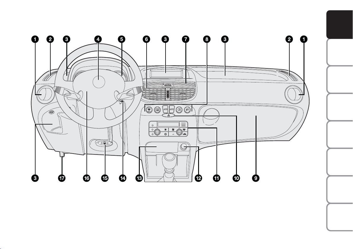
DASHBOARD
The presence and the position of the instruments and warning lights may vary according to the versions.
F0I0098m
1. Side swivel vent - 2. Side fixed vent - 3. Oddment compartment - 4. Horn - 5. Instrument panel - 6. Central swivel
vent - 7. Central fixed vent - 8. Central controls - 9. Glovebox - 10. Hazard light switch - 11. Controls for heating,
ventilation and climate control - 12. Cigar lighter - 13. Ashtray - 14. Ignition switch - 15. Steering wheel adjustment
lever - 16. Front passenger air bag - 17. Bonnet opening lever.
AND
CONTROLS
DASHBOARD
SAFETY
DEVICES
OF THE CAR
CORRECT USE
WARNING
MESSAGES
LIGHTS AND
IN AN
EMERGENCY
CAR
MAINTENANCE
TECHNICAL
SPECIFICATIONS
5
INDEX
Page 7
AND
CONTROLS
DASHBOARD
SAFETY
DEVICES
OF THE CAR
CORRECT USE
F0I0008m
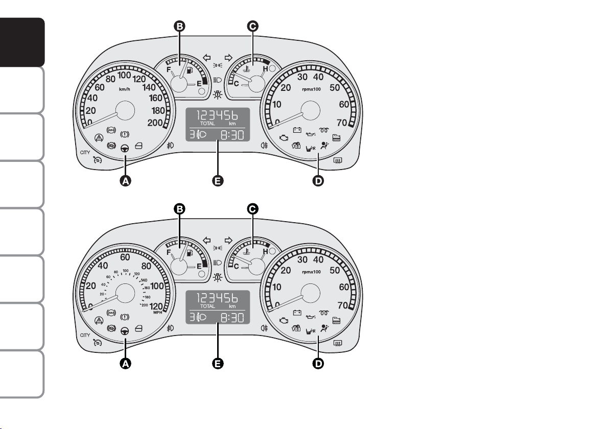
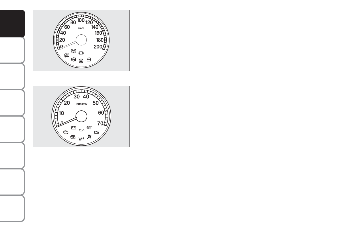
INSTRUMENT PANEL
ACTIVE, DYNAMIC versions
(A) - Speedometer (speed indicator)
(B) - Fuel level gauge with reserve
warning light
(C) - Engine coolant temperature gauge
and excessive temperature
warning light
(D) - Rev counter
(E) - Multifunction display
WARNING
MESSAGES
LIGHTS AND
IN AN
EMERGENCY
CAR
MAINTENANCE
TECHNICAL
SPECIFICATIONS
INDEX
6
Left-hand drive versions
Version for specific market
mcwarning lights fitted on diesel versions
F0I0011m
Page 8
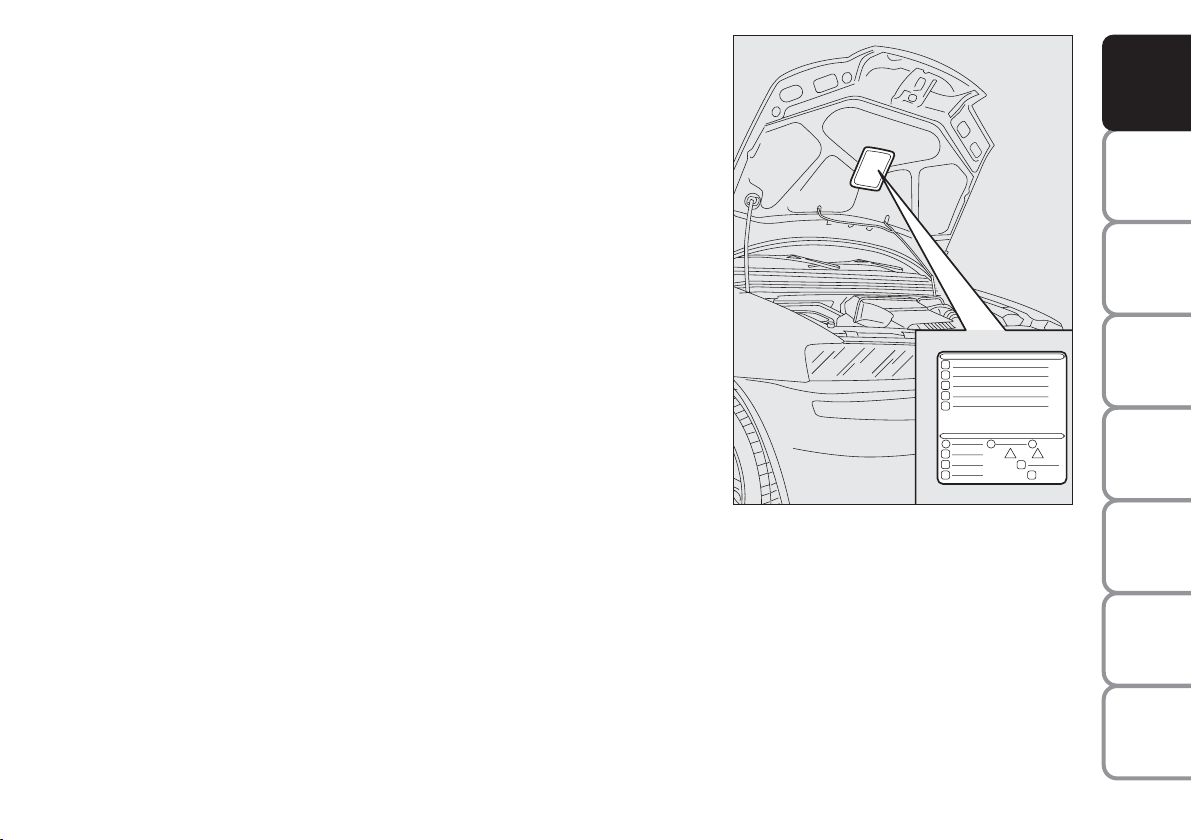
SYMBOLS
Special coloured labels have been attached near or actually on some of
the components of your Fiat Punto. These labels bear symbols that
remind you of the precautions to be taken as regards that particular
component.
The plate summarising the symbols used can be found under the bonnet.
THE FIAT CODE SYSTEM
To further protect you car from theft, it has been fitted with an engine
immobilising system. This system is automatically activated when the
ignition key is removed.
An electronic device, in fact, is fitted in each ignition key grip. The device
transmits a radio-frequency signal when the engine is started through a
special aerial built into the ignition switch. The modulate signal, which
changes each time the engine is started, is the password by means of
which the control unit recognises the key and enables to start the engine.
OPERATION
Each time the car is started turning the ignition key to MAR, the Fiat
CODE system control unit sends a recognition code to the engine
control unit to deactivate the inhibitor.
The code is sent only if the Fiat CODE system control unit has
recognised the code transmitted from the key.
Each time the ignition key is turned to the STOP position, the Fiat CODE
system deactivates the functions of the engine electronic control unit.
F0I0073m
AND
CONTROLS
DASHBOARD
SAFETY
DEVICES
OF THE CAR
CORRECT USE
WARNING
MESSAGES
LIGHTS AND
IN AN
EMERGENCY
CAR
MAINTENANCE
TECHNICAL
SPECIFICATIONS
7
INDEX
Page 9
AND
CONTROLS
DASHBOARD
SAFETY
DEVICES
OF THE CAR
CORRECT USE
WARNING
MESSAGES
LIGHTS AND
IN AN
EMERGENCY
CAR
MAINTENANCE
At starting, if the code has not been recognised
correctly, the warning light Ywill come on.
In this case, the key should be moved to the STOP
position and then back to MAR; if the lock continues,
possibly try again with the other key provided with the
car. If it is still not possible to start the car, follow the
instructions given in chapter “In an emergency” and
then contact a Fiat Dealership.
IMPORTANT Every key has its own code, which must
be memorised by the system control unit. To
memorise new keys, up to a maximum of eight, apply
to Fiat Dealership.
Warning light
❒ If the warning light
coming on when driving
Y
turns on, this means that
Y
the system is running a self-test (for example for a
voltage drop). At the first stop, turn the ignition key
to STOP and then to MAR again: if no failure is
detected warning light Ywill not come on.
❒ If the warning light
stays on, repeat the
Y
procedure described previously leaving the key at
STOP for over 30 seconds. Should the
inconvenience persists, contact a Fiat Dealership.
❒ If the warning light
stays on this means that the
Y
code has not been recognised. In this case, the key
should be moved to the STOP position and then
back to MAR; if the lock continues, possibly try
again with the other key provided with the car. If it
is still not possible to start the car, follow the
instruction given in chapter “In an emergency” and
then contact a Fiat Dealership.
TECHNICAL
SPECIFICATIONS
INDEX
8
The electronic components inside the key may be damaged if the key is submitted to sharp knocks.
Page 10
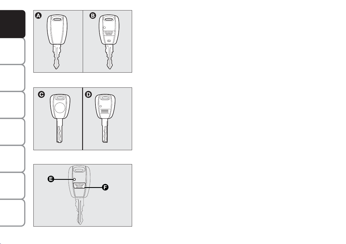
THE KEYS
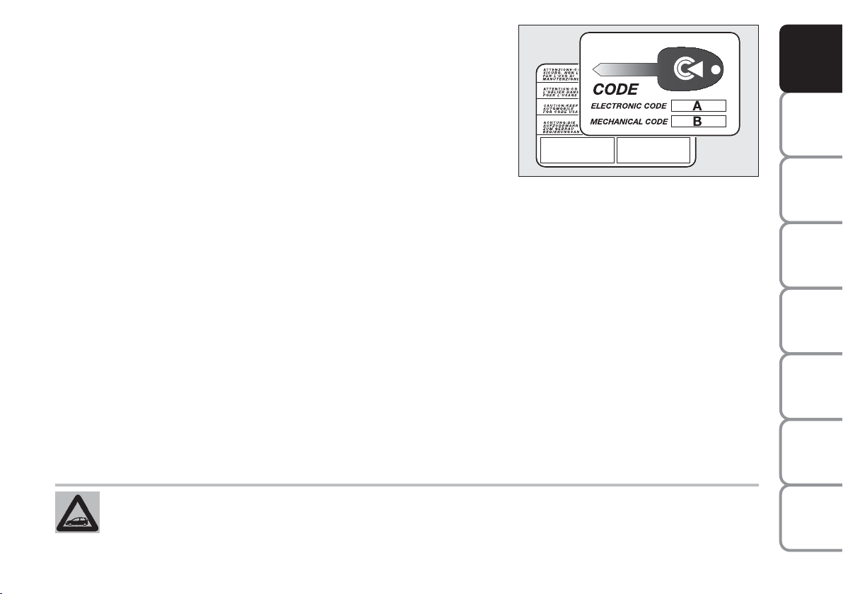
CODE CARD (where required)
The car is delivered with two copies of the key and the CODE card
which bears the following:
❒ the electronic code (A) to be used for emergency starting (see
“Emergency starting” in section “Correct use of the car”)
❒ the mechanical key code (B) to be given to the Fiat Dealership when
ordering duplicate keys.
Make sure you have the electronic code (A) with you at all times in the
event you have to perform an emergency start-up.
IMPORTANT In order to ensure perfect efficiency of the electronic
devices contained inside the keys, they should never be exposed to direct
sunlight.
U.K. VEHICLES ONLY
At the behest of the motor Insurance Companies the CODE card for
emergency starting and remplacement of keys is not provided. If you
need assistance please contact your nearest Fiat Dealership or telephone
Free Phone 0800 717000.
F0I0036m
AND
CONTROLS
DASHBOARD
SAFETY
DEVICES
OF THE CAR
CORRECT USE
WARNING
MESSAGES
LIGHTS AND
IN AN
EMERGENCY
CAR
MAINTENANCE
All the keys and the CODE card must be handed over to the new owner when selling the car.
TECHNICAL
INDEX
9
SPECIFICATIONS
Page 11
AND
CONTROLS
DASHBOARD
SAFETY
DEVICES
OF THE CAR
CORRECT USE
WARNING
MESSAGES
LIGHTS AND
IN AN
EMERGENCY
CAR
MAINTENANCE
TECHNICAL
SPECIFICATIONS
INDEX
F0I0038m
F0I0267m
KEY WITHOUT REMOTE CONTROL
Key (A) (or (C) in alternative), delivered in two copies when the car is
not fitted with remote control, controls the following:
❒ the ignition switch;
❒ the door and boot locks;
❒ the fuel filler cap locking/unlocking (versions with fuel filler cap with
keylock);
❒ the switch to deactivate the passenger’s air bag (where provided).
KEY WITH REMOTE CONTROL (where provided)
Key (B) (or (D) in alternative), delivered together with key (A) or (C)
when the car is fitted with remote control, controls the following:
❒ the ignition switch;
❒ the door and boot locks;
❒ the fuel filler cap locking/unlocking (versions with fuel filler cap with
keylock);
❒ the switch to deactivate the passenger’s air bag (where provided).
Button (F) operates remote door locking/unlocking.
Led (E-where provided) comes on when sending the control to the
system receiver.
When unlocking the doors, the internal lights will come on for a preset
length of time.
IMPORTANT Certain radio devices outside the car (e.g. mobile phones,
HAM radio systems) could disturb the remote control frequency. In this
case the remote control could malfunction.
10
F0I0039m
Page 12
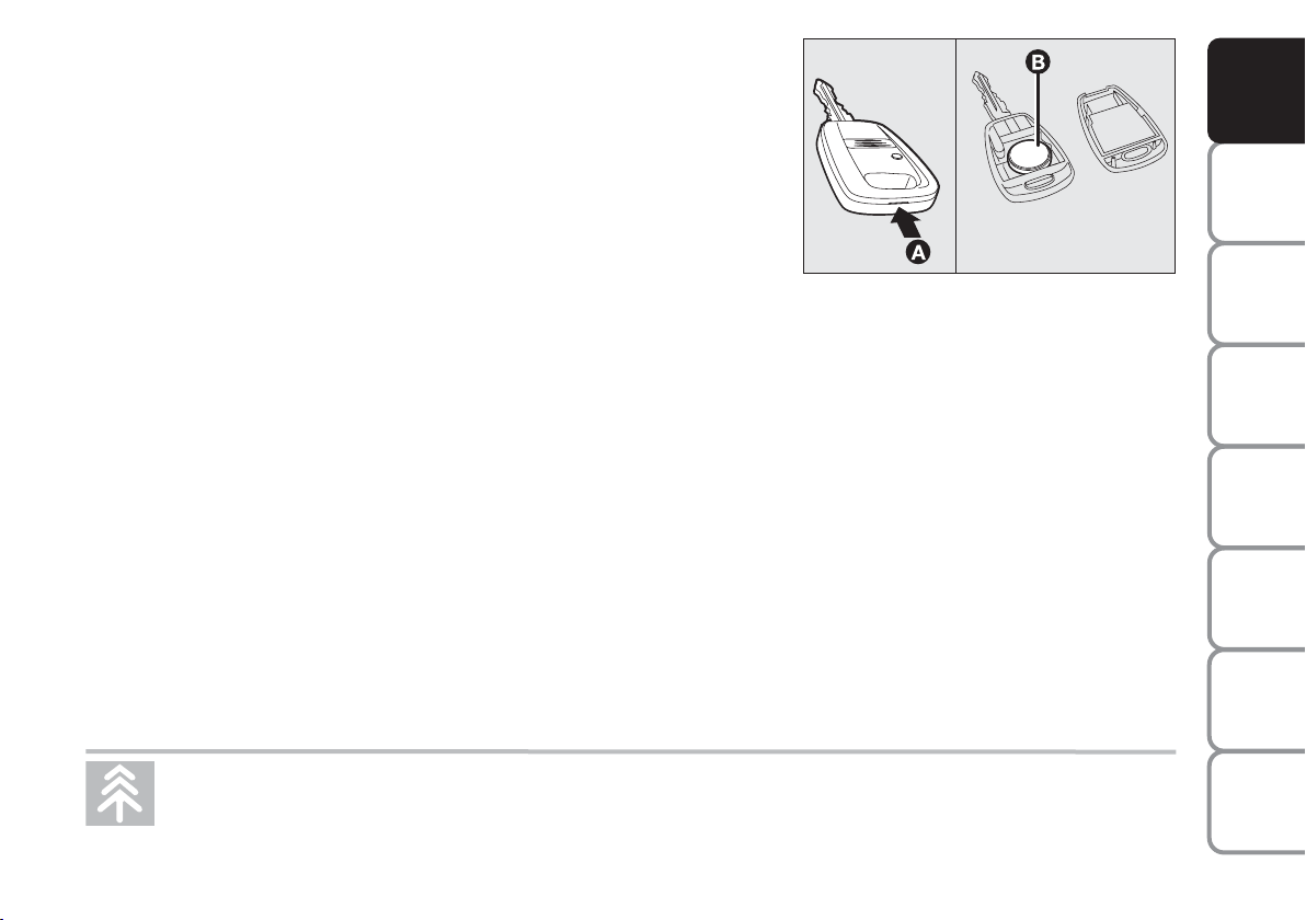
Replacing the battery of the key with remote control
If when pressing the remote control button, the led on the key flashes
briefly only once, the battery should be replaced with an equivalent one
that can be purchased at common stores.
Battery replacement:
❒ open the plastic case by inserting a screwdriver in recess (A);
❒ remove the run-down battery (B) and insert the new one respecting
the polarity;
❒ close the plastic case.
Request for additional remote controls
The system can recognise up to 8 keys with incorporated remote
control. Should a new key with remote control be necessary, contact a
Fiat Dealership, taking with you the CODE card, a personal identity
document and the car’s ownership documents.
F0I0040m
AND
CONTROLS
DASHBOARD
SAFETY
DEVICES
OF THE CAR
CORRECT USE
WARNING
MESSAGES
LIGHTS AND
IN AN
EMERGENCY
CAR
MAINTENANCE
Used batteries are harmful to the environment. They should be disposed of as specified by law in
the special containers provided, or take them to a Fiat Dealership, which will deal with their
disposal.
TECHNICAL
INDEX
11
SPECIFICATIONS
Page 13
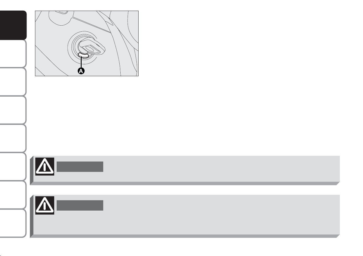
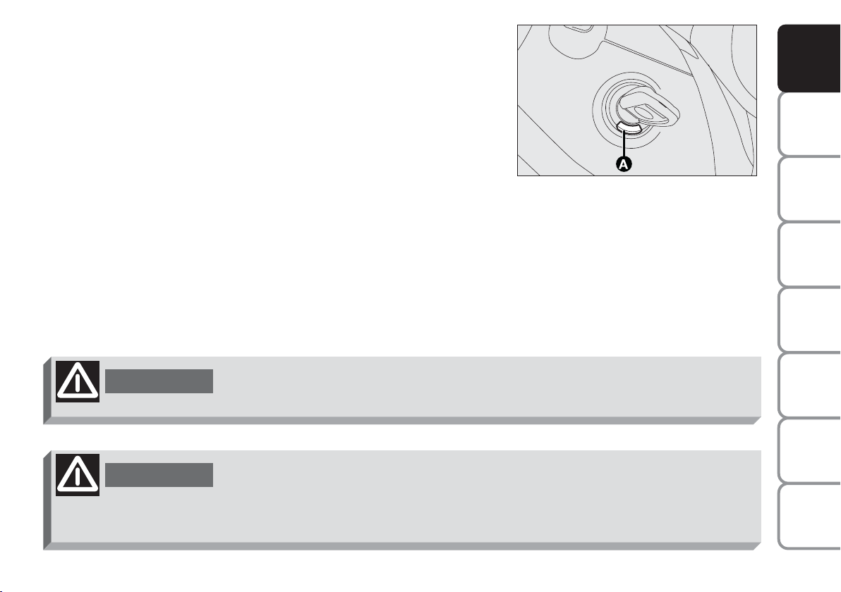
IGNITION SWITCH
AND
CONTROLS
DASHBOARD
SAFETY
DEVICES
OF THE CAR
CORRECT USE
WARNING
MESSAGES
LIGHTS AND
IN AN
EMERGENCY
CAR
MAINTENANCE
TECHNICAL
SPECIFICATIONS
INDEX
WARNING
WARNING
The key can be turned to 4 different positions:
❒ STOP: engine off, key can be removed, steering column locked.
Certain electrical devices (e.g.: sound system, power windows, etc.)
can work.
❒ MAR: driving position. All electrical devices are powered.
F0I0035m
❒ AVV: engine starting.
❒ PARK: engine off, parking lights on, steering column locked. To turn
the key to PARK, press button (A).
The ignition switch is fitted with a safety mechanism that, in the event the
engine is not started, turns back the ignition key to STOP before epeating
the starting operation.
If the ignition device is tampered with (e.g.: attempted theft), have it checked over
by a Fiat Dealership.
When getting out of the car, always remove the key to prevent any occupants
from accidentally activating the controls. Remember to engage the
handbrake. If the car is parked on uphill slope to engage the first gear. If the
car is facing downhill, engage the reverse gear. Never leave unsupervised
children in the car.
12
Page 14
STEERING COLUMN LOCK
Engaging
When the key is to STOP or PARK remove the key and turn the steering
wheel until it locks.
Disengaging
Rock the steering wheel slightly as you turn the ignition key to MAR.
Never remove the ignition key while the car is moving. The steering wheel would
WARNING
automatically lock as soon as you try to turn it. This also applies when the car is
being towed.
It is absolutely forbidden to carry out whatever after-market operation involving
WARNING
steering system or steering column modifications (e.g.: installation of anti-theft
device) that could badly affect performance and safety, cause the lapse of
warranty and also result in non-compliance of the car with homologation
requirements.
F0I0035m
AND
CONTROLS
DASHBOARD
SAFETY
DEVICES
OF THE CAR
CORRECT USE
WARNING
MESSAGES
LIGHTS AND
IN AN
EMERGENCY
CAR
MAINTENANCE
TECHNICAL
SPECIFICATIONS
INDEX
13
Page 15
INSTRUMENTS
AND
CONTROLS
DASHBOARD
SAFETY
DEVICES
OF THE CAR
CORRECT USE
WARNING
MESSAGES
LIGHTS AND
IN AN
EMERGENCY
CAR
MAINTENANCE
TECHNICAL
SPECIFICATIONS
F0I0229m
F0I0042m
Instrument background and type can change according to versions.
SPEEDOMETER (SPEED INDICATOR)
It indicates the car speed.
REV. COUNTER
The rev. counter shows engine rpm. The needle pointed to the danger
area (red on certain versions) indicates excessive high engine speed. Do
not drive for long periods with the needle in this area.
IMPORTANT The electronic injection control system gradually shuts off
the flow of fuel when the engine is “over-revving” resulting in a gradual
loss of engine power.
When the engine is idling, the rev counter may indicate a gradual or
sudden highering of the speed.
This is normal as it takes place during normal operation, for example
when activating the climate control system or the fan. In particular a slow
change in the speed preserves the battery charge.
INDEX
14
Page 16
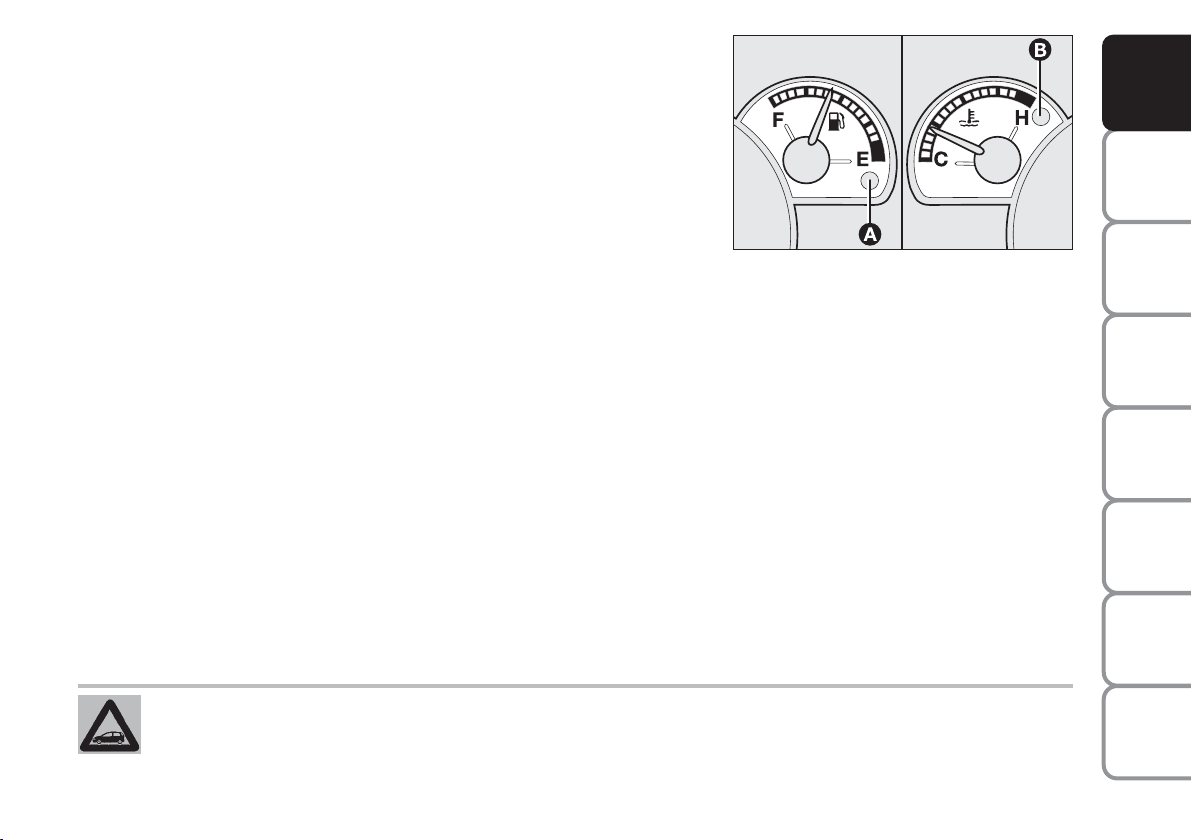
FUEL LEVEL GAUGE
The needle indicates the amount of fuel left in the tank.The reserve
warning light (A) turns on (on certain versions together with the message
shown on the reconfigurable multifunction display) to indicate that 5 to 7
litres of fuel are left in the tank.
E - tank empty.
F - tank full (see contents of “At the filling station” paragraph in this
chapter).
Do not travel with the fuel tank almost empty: the gaps in fuel delivery
could damage the catalyst.
IMPORTANT If the needle reaches the (E) with warning light (A) flashing
this means that there is a failure. Contact a Fiat Dealership.
F0I0041m
AND
CONTROLS
DASHBOARD
SAFETY
DEVICES
OF THE CAR
CORRECT USE
ENGINE COOLANT TEMPERATURE GAUGE
This shows the temperature of the engine coolant fluid and begins working when the fluid temperature exceeds
approx. 50°C.
Under normal conditions, the needle should hover around the middle of the scale according to the working
conditions.
C - low engine coolant temperature.
H - excessive engine coolant temperature.
The turning on of the warning light (B) (on certain versions together with the message shown on the reconfigurable
multifunction display) indicates that the coolant fluid temperature is too high; in this case, stop the engine and
contact a Fiat Dealership.
If the needle reaches the red area, stop the engine immediately and contact a Fiat Dealership.
WARNING
IN AN
CAR
TECHNICAL
INDEX
15
MESSAGES
LIGHTS AND
EMERGENCY
MAINTENANCE
SPECIFICATIONS
Page 17
AND
¯
¯
7
1
ŸΔ
CONTROLS
DASHBOARD
SAFETY
DEVICES
F0I0063m
CONTROL BUTTONS
To use the information the “Digital display”, “Multifunction display” and
“Reconfigurable multifunction display” are able to give (with the ignition
key at MAR), you should firstly familiarise with the control buttons on
the right and left side of the instrument panel and on the top of the right
stalk (for the “Trip computer” function) (where provided) using them as
described below.
Before doing anything you are also advised to read this chapter
thoroughly.
OF THE CAR
CORRECT USE
WARNING
MESSAGES
LIGHTS AND
IN AN
EMERGENCY
CAR
MAINTENANCE
TECHNICAL
SPECIFICATIONS
INDEX
16
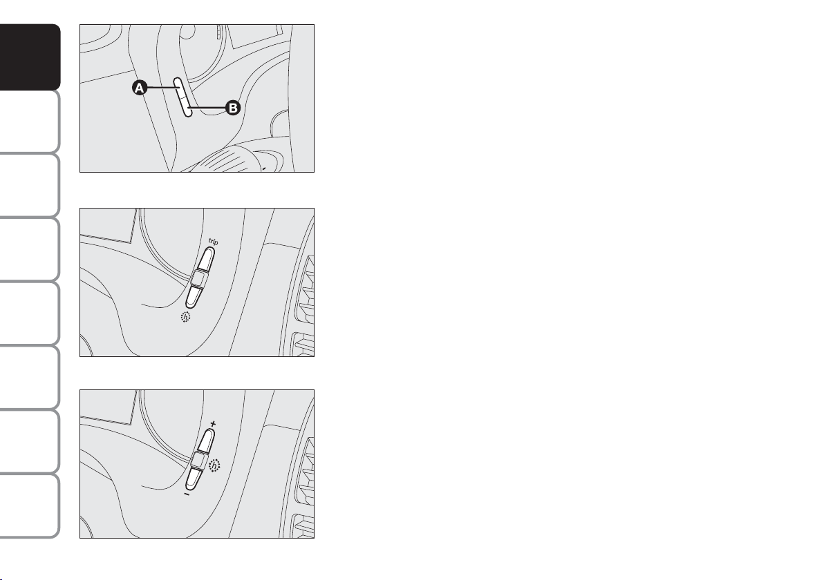
Headlight beam adjusting device
The left-hand side of the instrument panel features two buttons (A and B)
for adjusting the headlight beam according to the transported load.
Buttons can be operated with ignition key at MAR and dipped beam
headlights on. See paragraph "Headlights" in this section for further
details.
Digital display (where provided)
Trip button
F0I0245m
To show on the display: total and trip km/miles.
Press briefly: to switch between total and trip km/miles.
Press for over 2 seconds: to reset trip km/miles.
h button
Set clock.
Multifunction display (where provided)
+/– button
F0I0244m
Button +: set clock (to increase minutes)
Button – : set clock ( to decrease minutes)
Page 18
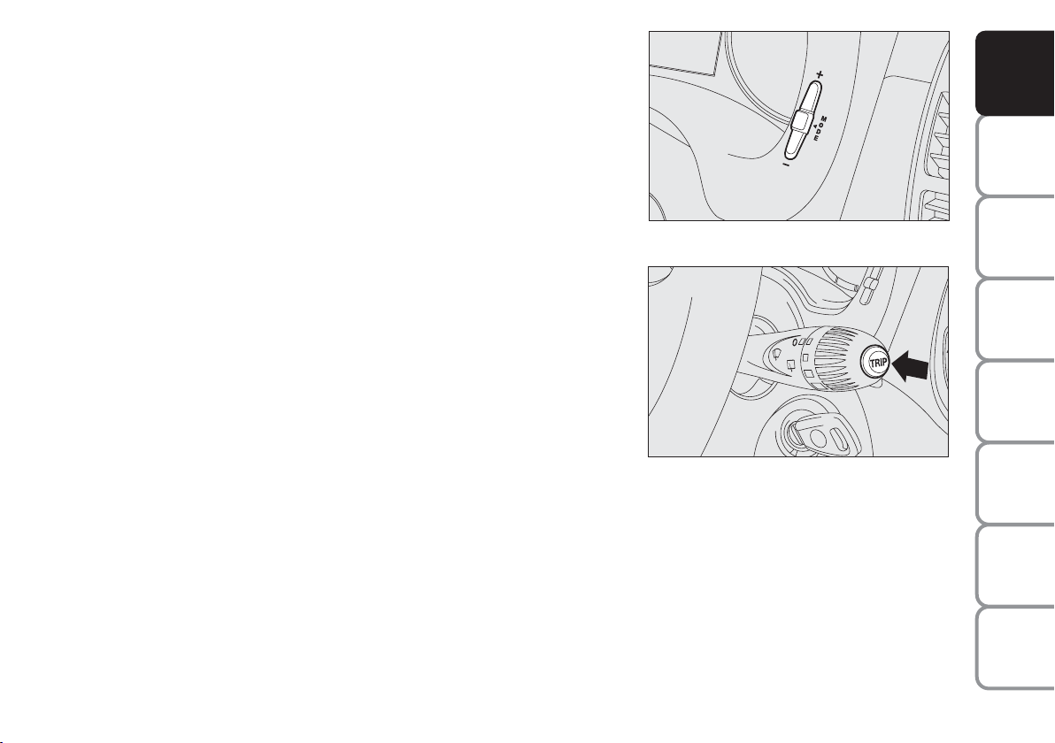
Reconfigurable multifunction display (where provided)
+/– buttons
To scroll the menu and the related options upwards/downwards or to
increase/decrease the value displayed, to adjust, with sidelights turned on,
the dimmer and the instrument panel and automatic two-zone climate
control system (where provided) display/index (if pressed with “Set-up
menu” off).
MODE button
Press for less than 2 seconds (pulse) indicated with Qin the following
diagrams, to confirm the option required and/or move to the main menu
(same option), or access the menu.
Press for over 2 seconds, indicated with
in the following diagrams, to
R
exit the set-up menu without confirming the selections being set.
TRIP button (for multifunction display and reconfigurable
multifunction display)
Press for less than 1 second (pulse) indicated with
in the following
%
diagrams, to scroll the Trip computer display.
Press for more than 2 seconds indicated with
in the following
&
diagrams, to reset the Trip computer and start a new mission.
F0I0242m
F0I0043m
AND
CONTROLS
DASHBOARD
SAFETY
DEVICES
OF THE CAR
CORRECT USE
WARNING
MESSAGES
LIGHTS AND
IN AN
EMERGENCY
CAR
MAINTENANCE
TECHNICAL
SPECIFICATIONS
17
INDEX
Page 19
AND
2
D
CONTROLS
DASHBOARD
SAFETY
DEVICES
OF THE CAR
CORRECT USE
WARNING
MESSAGES
LIGHTS AND
IN AN
EMERGENCY
CAR
MAINTENANCE
F0I0209m
F0I0210m
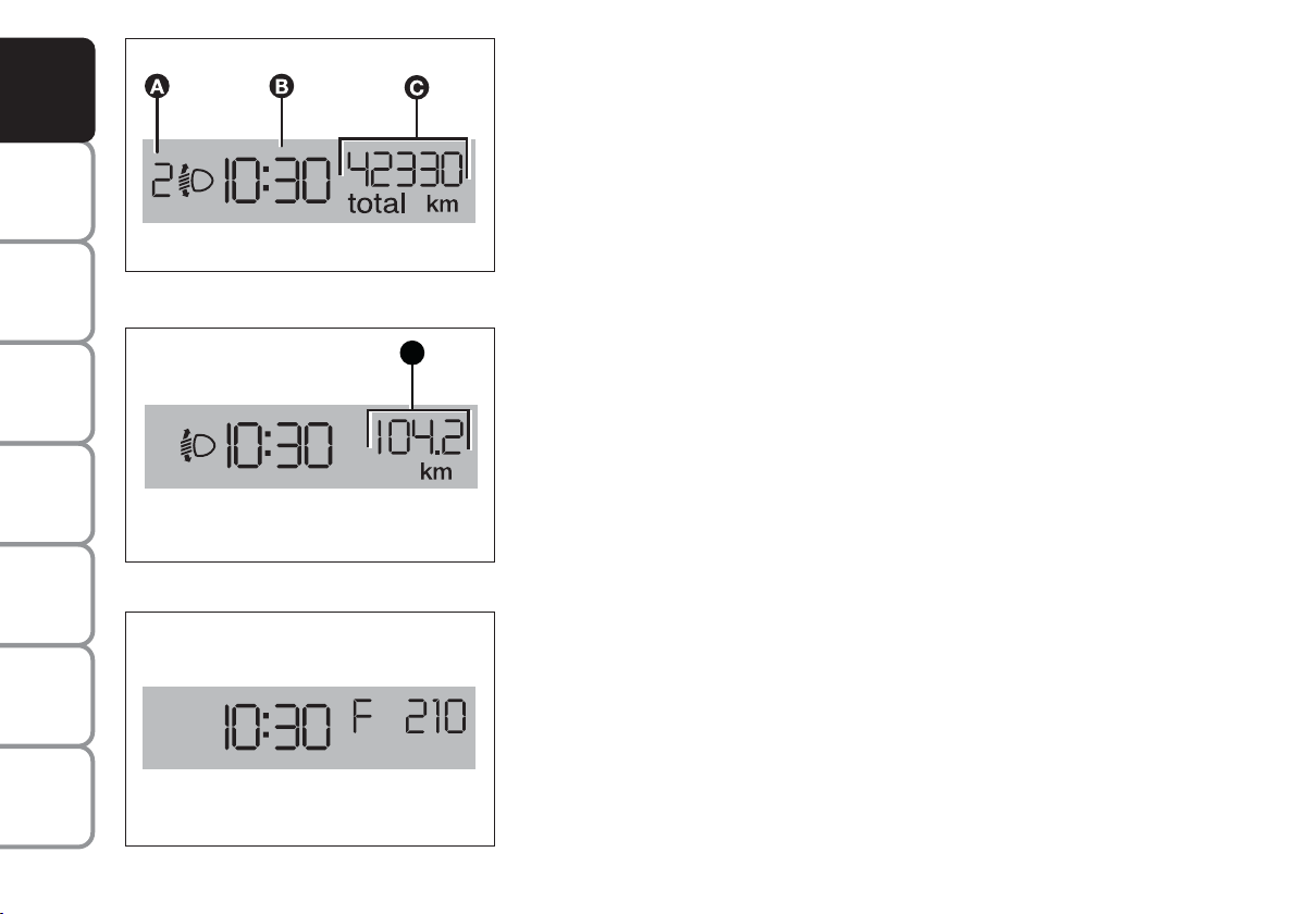
DIGITAL DISPLAY (where provided)
DISPLAY INFO
❒ Headlight aiming position display (only with dipped beams on) (A)
❒ Clock (B) (always displayed, also with key removed and front doors
closed).
❒ Total (C) and partial (D) odometer.
With ignition key removed, when opening one of the front doors the
display comes on showing the clock and the odometer indication.
If the “Follow me home” function is on (see paragraph “Follow me
home” in this section), the display will show the time the function is on
instead of the mileage recorder indication (see figure).
TECHNICAL
SPECIFICATIONS
INDEX
F0I0222m
18
Page 20
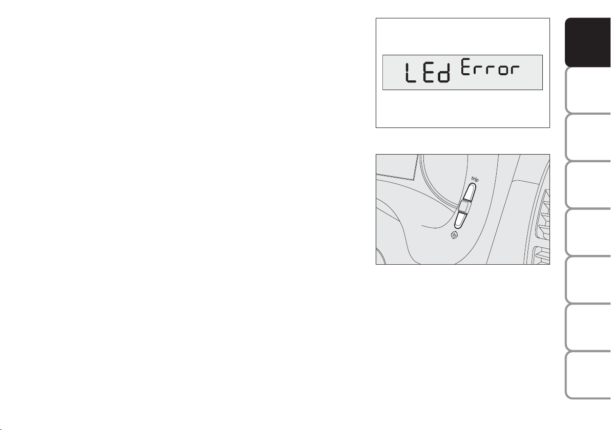
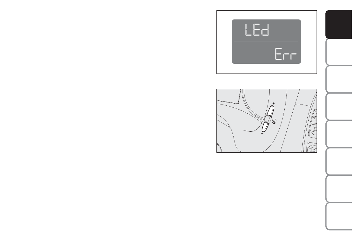
Warning light check function
The instrument panel performs a check on the following warning lights:
❒ handbrake on/low brake fluid level;
❒ ABS and EBD system;
❒ ESP system on/failure;
❒ “Dualdrive” (where provided) electric power steering failure.
Warning light check is performed automatically when turning the ignition
key to MAR and during normal operation if a failure is detected.
When the initial check is over, the message LEd Error will flash on the
display for about 10 seconds to warn the driver that a failure has been
detected (on one or more warning lights).
SET CLOCK
Press button h. Each pulse on the button will obtain increase by one unit.
Automatic fast increase is obtained by keeping the button pressed for few
seconds. When you are near the required value, release the button and
complete adjustment with single presses.
F0I0223m
F0I0245m
AND
CONTROLS
DASHBOARD
SAFETY
DEVICES
OF THE CAR
CORRECT USE
WARNING
MESSAGES
LIGHTS AND
IN AN
EMERGENCY
CAR
MAINTENANCE
TECHNICAL
INDEX
19
SPECIFICATIONS
Page 21
MULTIFUNCTION DISPLAY (where provided)
AND
CONTROLS
DASHBOARD
SAFETY
DEVICES
OF THE CAR
CORRECT USE
WARNING
MESSAGES
LIGHTS AND
IN AN
EMERGENCY
CAR
MAINTENANCE
TECHNICAL
SPECIFICATIONS
F0I0031m
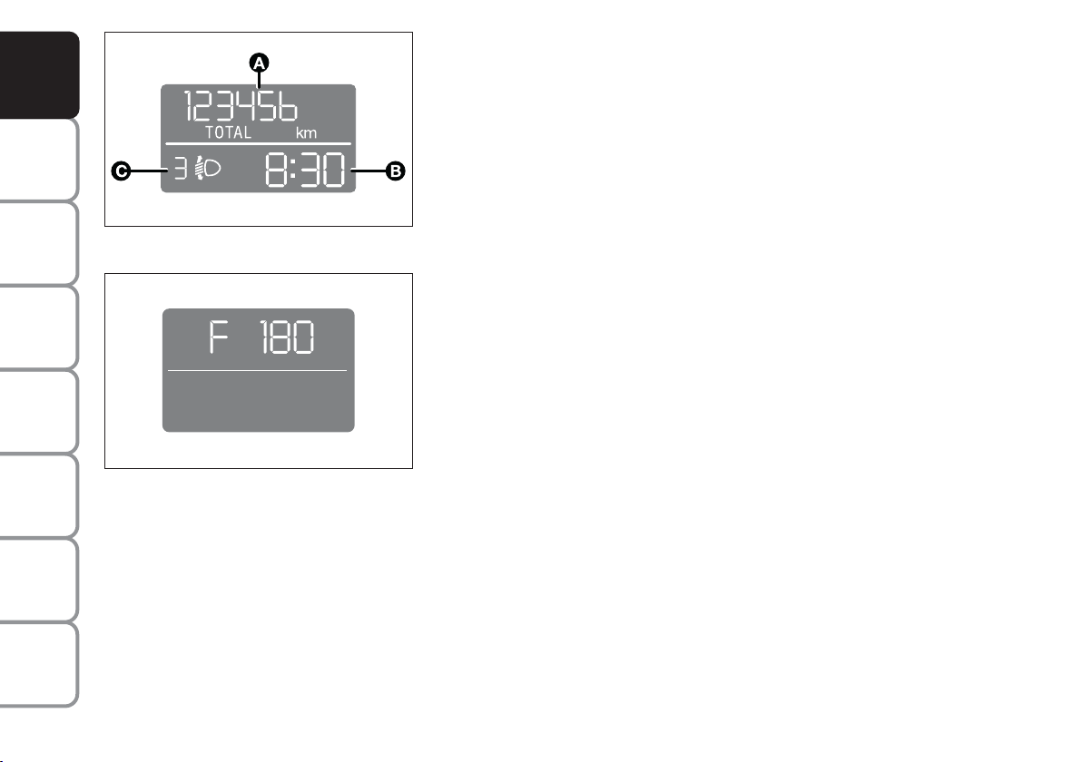
F0I0030m
The “Multifunction display” shows all the useful information necessary
when driving, more particularly:
INFORMATION ON STANDARD SCREEN
❒ Total odometer (A).
❒ Clock (B).
With ignition key removed and front doors closed the display is off.
With ignition key removed, when opening one of the front doors the
display comes on showing the clock and the odometer indication.
If the “Follow me home” function is on (see paragraph “Follow me home”
in this section), the display will show the time the function is on instead of
the mileage recorder indication (see figure).
INFORMATION ABOUT CAR CONDITIONS (at event)
❒ Trip computer information.
❒ Headlight aiming position display (with dipped beam headlights on) (C).
INDEX
20
Page 22
TRIP COMPUTER
Pressing button
, the “Trip computer” function gives is displayed,
{
information relating to the operating status of the car. This function is
resettable.
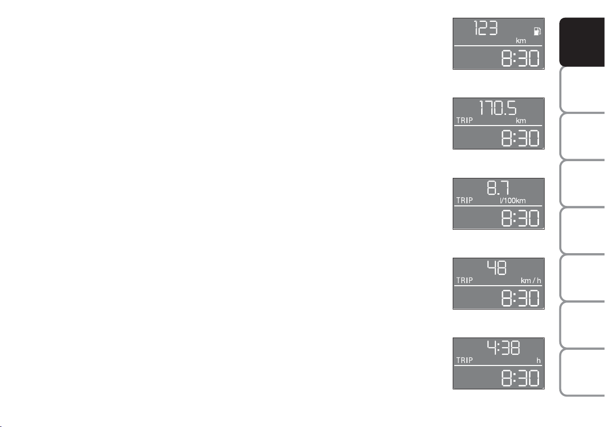
Values displayed are: Range to empty, Distance travelled, Average
consumption, Instant consumption, Average speed, Trip time (driving
time). Value selected will be displayed until a new information is
requested.
(*) When the Instant consumption value is displayed, the word TRIP will
not be displayed.
Start of journey procedure (reset)
To start a new journey, with the key to MAR, press button
{
with
mode &(see paragraph “Control buttons”).
IMPORTANT “Range to empty” information cannot be reset.
Range to empty
Distance travelled
F0I0164m
F0I0165m
AND
CONTROLS
DASHBOARD
SAFETY
DEVICES
OF THE CAR
CORRECT USE
WARNING
MESSAGES
LIGHTS AND
Average/instant
consumption (*)
Average speed
Trip time
F0I0166m
F0I0167m
F0I0168m
IN AN
CAR
TECHNICAL
INDEX
21
EMERGENCY
MAINTENANCE
SPECIFICATIONS
Page 23

AND
CONTROLS
DASHBOARD
SAFETY
DEVICES
OF THE CAR
CORRECT USE
WARNING
MESSAGES
LIGHTS AND
IN AN
EMERGENCY
CAR
MAINTENANCE
Range to empty = shows the distance in km (or
miles) that the car can still cover before needing fuel,
assuming that driving conditions are kept unvaried.
The display will show “- - - -” in the following cases:
❒ range lower than 50 km;
❒ car parked with engine running for long time; when
restarting range indication will be displayed again
Distance travelled = shows the km (or miles)
covered from the start of the new mission (*).
Average consumption = shows the average
consumption calculated from the start of the new
mission (*); this value can be expressed in km/l or
l/100 km or in mpg.
Instant consumption = shows fuel consumption
variation, this value is updated constantly. If the car is
parked with engine running the display will show
“- - - -”. When restarting the car, the instant
consumption indication will be displayed again.
Average speed = shows the average speed of the
car in relation with total time elapsed from the start of
the new mission (*).
Trip time = time elapsed from the start of the new
mission (*).
(*) New mission = starts from last reset:
– “manual” reset is performed by the driver by
pressing the relevant button (see paragraph
“Control buttons”)
– “automatic” reset is performed when the Distance
travelled reaches 3999.9 km or when Trip Time
reaches 99:59 (99 hours and 59 minutes)
– after reconnecting the battery.
IMPORTANT Lacking information, Trip computer
values are displayed with “- - - -”. When restoring
normal operating conditions after a failure, calculation
will restart regularly without resetting either previous
displayed values or the start of a new mission (*).
IMPORTANT After disconnecting/reconnecting the
battery, certain displayed values will be equal to
“- - - -” until significant data for recalculation are
available.
TECHNICAL
SPECIFICATIONS
INDEX
22
Page 24
WARNING LIGHT CHECK FUNCTION
The instrument panel performs a check on the following warning lights:
❒ handbrake on/low brake fluid level;
❒ ABS and EBD system;
❒ ESP system on/failure;
❒ “Dualdrive” (where required) electric power steering failure.
Warning light check is performed automatically when turning the ignition
key to MAR and during normal operation if a failure is detected. When
the initial check is over, the message LEd Err will flash on the display for
about 10 seconds to warn the driver that a failure has been detected (on
one or more warning lights.
F0I0032m
AND
CONTROLS
DASHBOARD
SAFETY
DEVICES
OF THE CAR
CORRECT USE
SET CLOCK
To adjust the time, press button (+) to increase minutes, button (–) to
decrease minutes. Every press on the button increases or decreases by
one unit. Keeping the corresponding button pressed obtains automatic
fast increase or decrease. When you are near the required value, release
the button and complete adjustment with single presses.
F0I0244m
WARNING
IN AN
CAR
TECHNICAL
INDEX
23
MESSAGES
LIGHTS AND
EMERGENCY
MAINTENANCE
SPECIFICATIONS
Page 25
AND
CONTROLS
DASHBOARD
SAFETY
DEVICES
OF THE CAR
CORRECT USE
WARNING
MESSAGES
LIGHTS AND
IN AN
EMERGENCY
CAR
MAINTENANCE
TECHNICAL
SPECIFICATIONS
INDEX
F0I1000g
F0I1001g
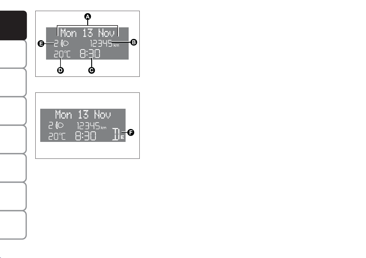
RECONFIGURABLE MULTIFUNCTION
DISPLAY (where provided)
The “Multifunction display” shows all the useful information necessary
when driving, more particularly:
INFORMATION ON STANDARD SCREEN
❒ Date (A).
❒ Total odometer (B).
❒ Clock (C).
❒ External temperature (D).
❒ Speedgear or Dualogic info display (where provided) (F).
With ignition key removed and front doors closed the display is off.
With ignition key removed, when opening one of the front doors the
display comes on showing the clock and the odometer indication.
If the “Follow me home” function is on (see paragraph “Follow me
home” in this section), the display will show the time the function is on
(see section “Warning lights and messages”).
INFORMATION ABOUT CAR CONDITIONS (at event)
❒ Scheduled maintenance programme intervals.
❒ Trip computer information.
❒ Light adjustment of graphics/index/instrument cluster display and two-
zone climate control system (where provided).
❒ Display of failure/warning/function activation messages.
24
Page 26

❒ Headlight aiming position display (with dipped beam
headlights on) (E).
❒ Repetition of audio info.
There is also a menu enabling to perform the following
adjustments and/or settings using the control buttons
(see previous pages):
SET-UP MENU
The number of items in the menu depends on the car
settings.
When travelling, only the “Speed limit” indication is
enabled.
The “Set-up Menu” enables to perform the following
adjustments and/or settings using the control buttons
(see previous pages):
❒ SPEED LIMIT
❒ TRIP B ON/OFF
❒ SET CLOCK
❒ CLOCK MODE
❒ SET DATE
❒ AUDIO REPETITION (where provided) (●)
❒ SPEEDLOCK (where provided)
❒ DISTANCE UNIT
❒ CONSUMPTION UNIT
❒ TEMPERATURE UNIT
❒ LANGUAGE
❒ BUZZER VOLUME
❒ BUTTON VOLUME
❒ SERVICE
❒ EXIT MENU
(●) “Audio Rpt.” menu item is present only if the car
is fitted, as standard, with sound system.
AND
CONTROLS
DASHBOARD
SAFETY
DEVICES
OF THE CAR
CORRECT USE
WARNING
MESSAGES
LIGHTS AND
IN AN
EMERGENCY
CAR
MAINTENANCE
TECHNICAL
INDEX
25
SPECIFICATIONS
Page 27
AND
CONTROLS
DASHBOARD
SAFETY
DEVICES
OF THE CAR
CORRECT USE
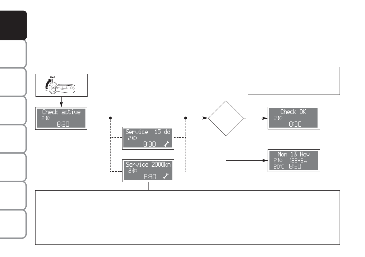
INITIAL CHECK
Turning the ignition key to MAR, the multifunction display shows the message “Check active”: the diagnostic phase
of all the electronic systems on the car has started. This lasts few seconds: if no faults are detected, when the engine
has started, the display shows the “Check OK” message. See section “Warning lights and messages” if faults are
found.
If the display shows a failure message,
see details in section “Warning lights
and messages”.
WARNING
MESSAGES
LIGHTS AND
IN AN
EMERGENCY
CAR
MAINTENANCE
TECHNICAL
SPECIFICATIONS
INDEX
26
Is the engine
started?
NO
or
The “Service schedule” includes vehicle maintenance every 20,000 km (or 12,000 mi) or every year; this is shown automatically, with the ignition key at MAR, starting from 2,000 km (or 1,240 miles) or 30 days from this deadline and it is shown again every 200 km (or 124 mi) or 3
days. For 1.3 Multijet versions, see “Care and Maintenance” in section “Service schedule to change engine oil and filter and air cleaner. Below
200 km service indications are proposed at shorter intervals. Below 200 km service indications are proposed at shorter intervals. Service intervals will be displayed in km or mi according to the unit set. When a programmed maintenance interval (coupon) is near to come, turning
the ignition key to MAR, will display the message “Service” followed by the number of km, or days to go before car servicing. “Scheduled servicing” message is displayed in km, miles or days according to the approaching service interval. Contact a Fiat Dealership to carry out any service operation provided by the “Service schedule” or “Annual inspection plan”, and to reset the display.
YES
If no failures are
present
Standard
screen display
Page 28
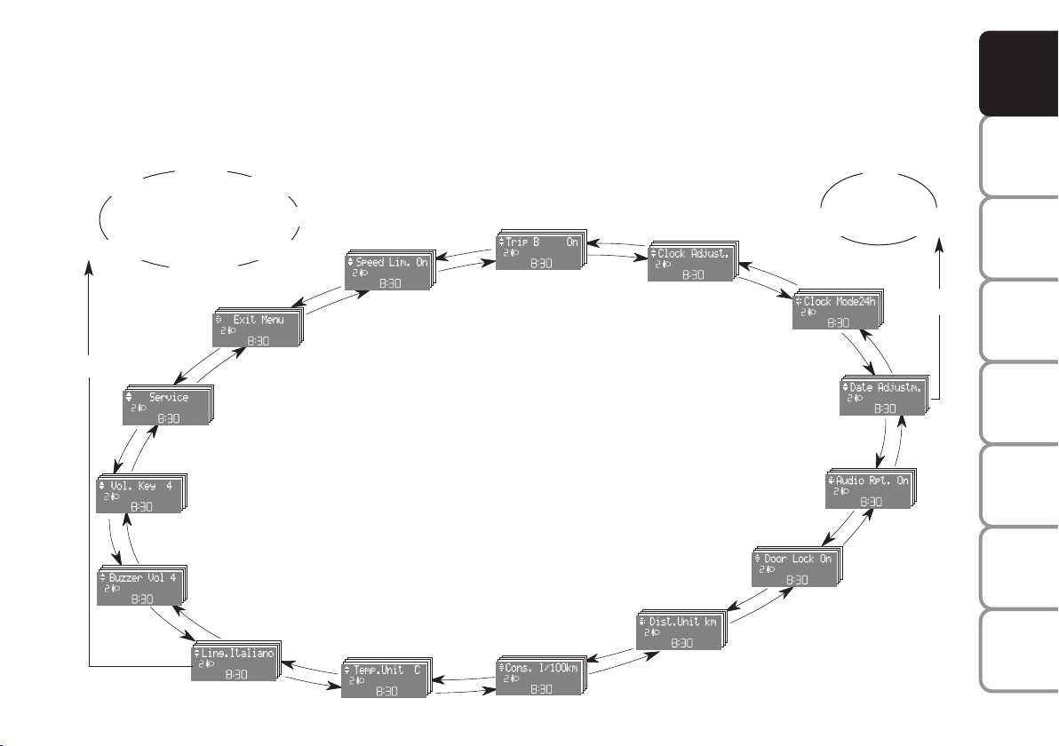
MENU DESCRIPTION
The menu comprises a series of functions arranged in a “circular fashion” which can be selected through buttons +
and - for access to the different select operations and settings (see examples “Lang.” and “Date adjustm.” below); for
further details, also refer to “Access to menu screen” on next page.
AND
CONTROLS
DASHBOARD
Italiano
Nederlan
Q
Example:
Deutsch
Português
KEYS VOLUME
BUZZER VOL
English
Español
Français
EXIT MENU
SERVICE
LANG. ENGLISH
SPEED LIM.
TEMP. UNIT
TRIP B
CONSUMP.
Example:
CLOCK ADJUST.
CLOCK MODE
DOOR LOCK
DIST. UNIT
Year Month
DATE ADJUSTM.
AUDIO RPT.
Day
Q
SAFETY
DEVICES
OF THE CAR
CORRECT USE
WARNING
MESSAGES
LIGHTS AND
IN AN
EMERGENCY
CAR
MAINTENANCE
TECHNICAL
SPECIFICATIONS
INDEX
27
Page 29

AND
CONTROLS
DASHBOARD
SAFETY
DEVICES
OF THE CAR
CORRECT USE
WARNING
MESSAGES
LIGHTS AND
IN AN
EMERGENCY
CAR
MAINTENANCE
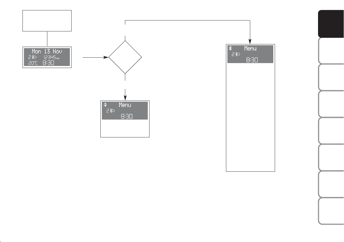
ACCESS TO MENU SCREEN
After the “Initial check”, it is possible to access the menu screen pressing the button
Q
.
To surf the menu press buttons + or –.
IMPORTANT If after entering the menu no setting/adjustment is performed within 60 seconds, the system exits the
menu automatically and returns to previously displayed screen. In this case the last selected but not confirmed
setting (through button
) is not stored and therefore the operation shall be repeated (this stands valid also when
Q
quitting the Menu by pressing the Rbutton).
When the car is running, it is possible to access only the reduced menu (for setting “Speed limit”).
When the car is stationary access to the whole menu is enabled.
The following diagram shows the cases described.
TECHNICAL
SPECIFICATIONS
INDEX
28
Page 30
See
“Initial check”
NO
AND
CONTROLS
DASHBOARD
Example of standard
screen
Q
Is the car
moving?
YES
Speed Lim.
Exit Menu
Reduced menu screen
Speed Lim.
Trip B
Clock Adjust.
Clock Mode
Date Adjustm.
Audio Rpt.
Door Lock
Dist. Unit
Consump
Temp. Unit
Lang.
Buzzer Vol
Keys Volume
Service
Exit menu
Extended menu screen
SAFETY
DEVICES
OF THE CAR
CORRECT USE
WARNING
MESSAGES
LIGHTS AND
IN AN
EMERGENCY
CAR
MAINTENANCE
TECHNICAL
SPECIFICATIONS
INDEX
29
Page 31
AND
CONTROLS
DASHBOARD
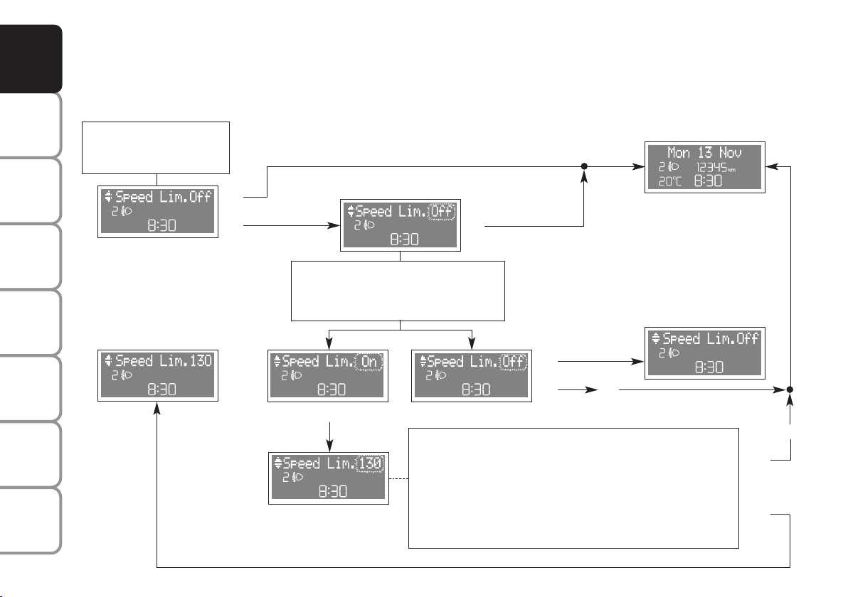
SPEED LIMIT (Speed Lim.)
With this function it is possible to set the car speed limit which, if exceeded, automatically sounds a buzzer and
è
makes the warning light
with the special message on the display (see “Warning lights and messages” section) come
on to alert the driver. To set the speed limit, proceed as follows:
SAFETY
DEVICES
OF THE CAR
CORRECT USE
WARNING
MESSAGES
LIGHTS AND
IN AN
EMERGENCY
CAR
MAINTENANCE
TECHNICAL
SPECIFICATIONS
INDEX
See “Initial check”
and “Access to
menu screen”
+
–
Menu screen
Return to menu
screen
R
Q
+
Use buttons +/– to select ON/OFF.
Set selection flashes.
–
Q
Use buttons +/- to set the speed required (during the setting operation the value flashes on the screen). The possible setting is between 30 and 250 km/h or between 20 and 155 mph dependingon the unit set previously (see “Distance Unit” paragraph
described later). Every press (pulse) of the button +/–
increases or decreases by five units. Keeping button +/– pressed
obtains the automatic fast increase or decrease. When you are
near the required setting, complete adjustment with single presses.
R
Q
Q
Return to previously
displayed
screen, e.g.:
Return to menu
screen
R
R
Q
Q
30
Page 32

TRIP B ON/OFF (Trip B)
Through this option it is possible to activate (ON) or deactivate (OFF) the Trip B (partial trip) which show “partial
mission” information corresponding to: Trip Dist. B, Avg. Consump. B, Avg. Speed B, Time B. For further
information see “General trip - Trip B”.
See “Initial check”
and “Access to
menu screen”
+
–
Menu screen
R
Q
Return to previously
displayed
screen, e.g.:
R
AND
CONTROLS
DASHBOARD
SAFETY
DEVICES
OF THE CAR
CORRECT USE
WARNING
MESSAGES
LIGHTS AND
Return to menu screen
Q
+
Use buttons +/– to select ON/OFF.
Set selection flashes.
–
Q
Q
R
R
Q
Return to menu screen
IN AN
CAR
TECHNICAL
INDEX
31
EMERGENCY
MAINTENANCE
SPECIFICATIONS
Page 33

AND
CONTROLS
DASHBOARD
SAFETY
DEVICES
OF THE CAR
CORRECT USE
WARNING
MESSAGES
LIGHTS AND
IN AN
EMERGENCY
CAR
MAINTENANCE
TECHNICAL
SPECIFICATIONS
INDEX
SET CLOCK (Clock Adjust.)
During setting, the clock is displayed in 24h mode regardless of the set clock mode (12h/24h).
To set the clock (hours - minutes) proceed as follows:
See “Initial check”
+
–
and “Access to
menu screen”
R
Q
Menu screen
Return to previously
displayed
screen, e.g.:
R
+
–
Every press (pulse) on button +/– increases or decreases
by one unit. Keeping button +/– pressed obtains automatic
fast increase or decrease. When you are near the required
setting, complete adjustment with single presses.
Q
Q
R
+
–
Q
Q
Return to previously
displayed
screen, e.g.:
R
Return to menu
screen
32
Page 34

CLOCK MODE (Clock Mode)
This function is used to set the clock in the 12h (12 hour) or 24h (24 hour) mode. To adjust proceed as follows:
AND
CONTROLS
DASHBOARD
See “Initial check”
and “Access to
menu screen”
+
–
Menu screen
Return to menu screen
R
Q
Q
Use buttons +/– to select 12 h or
+
24 h mode.
Set selection flashes.
–
Q
Q
R
R
Q
Return to previously
screen, e.g.:
Return to menu screen
displayed
SAFETY
DEVICES
OF THE CAR
CORRECT USE
WARNING
MESSAGES
LIGHTS AND
IN AN
EMERGENCY
CAR
MAINTENANCE
TECHNICAL
SPECIFICATIONS
INDEX
R
33
Page 35

AND
CONTROLS
DASHBOARD
SAFETY
DEVICES
SET DATE (Date Adjustm.)
To correct the date (year - month - day ) proceed as follows:
See “Initial check”
and “Access to
menu screen”
Return to previously
displayed
screen, e.g.:
Return to previously
displayed
screen, e.g.:
OF THE CAR
CORRECT USE
WARNING
MESSAGES
LIGHTS AND
IN AN
EMERGENCY
CAR
MAINTENANCE
TECHNICAL
SPECIFICATIONS
INDEX
34
+
–
Menu screen
+
–
R
Q
R
Q
+
–
Every press (pulse) on button +/– increases or decreases
by one unit. Keeping button +/– pressed obtains
automatic fast increase or decrease. When you are near
the required setting, complete adjustment with single
presses.
R
R
Q
Q
R
+
–
Q
Q
Return to menu screen
Page 36

AUDIO REPETITION (Audio Rpt.) (where provided)
With this function the display repeats information relevant to the Radio (selected radio station frequency or RDS
message, automatic tuning or AutoSTore), audio CD (track number).
AND
CONTROLS
DASHBOARD
See “Initial check”
and “Access to
menu screen”
+
–
Menu screen
Return to menu screen
Example of audio
repetition
R
Q
Q
+
Use buttons +/– to select ON/OFF.
Set selection flashes
–
Q
Q
R
R
R
Q
Return to previously
displayed screen, e.g.:
Return to menu
screen
SAFETY
DEVICES
OF THE CAR
CORRECT USE
WARNING
LIGHTS AND
IN AN
EMERGENCY
CAR
MAINTENANCE
TECHNICAL
SPECIFICATIONS
INDEX
35
MESSAGES
Page 37
AND
CONTROLS
DASHBOARD
SAFETY
DEVICES
OF THE CAR
CORRECT USE
WARNING
MESSAGES
LIGHTS AND
IN AN
EMERGENCY
CAR
MAINTENANCE
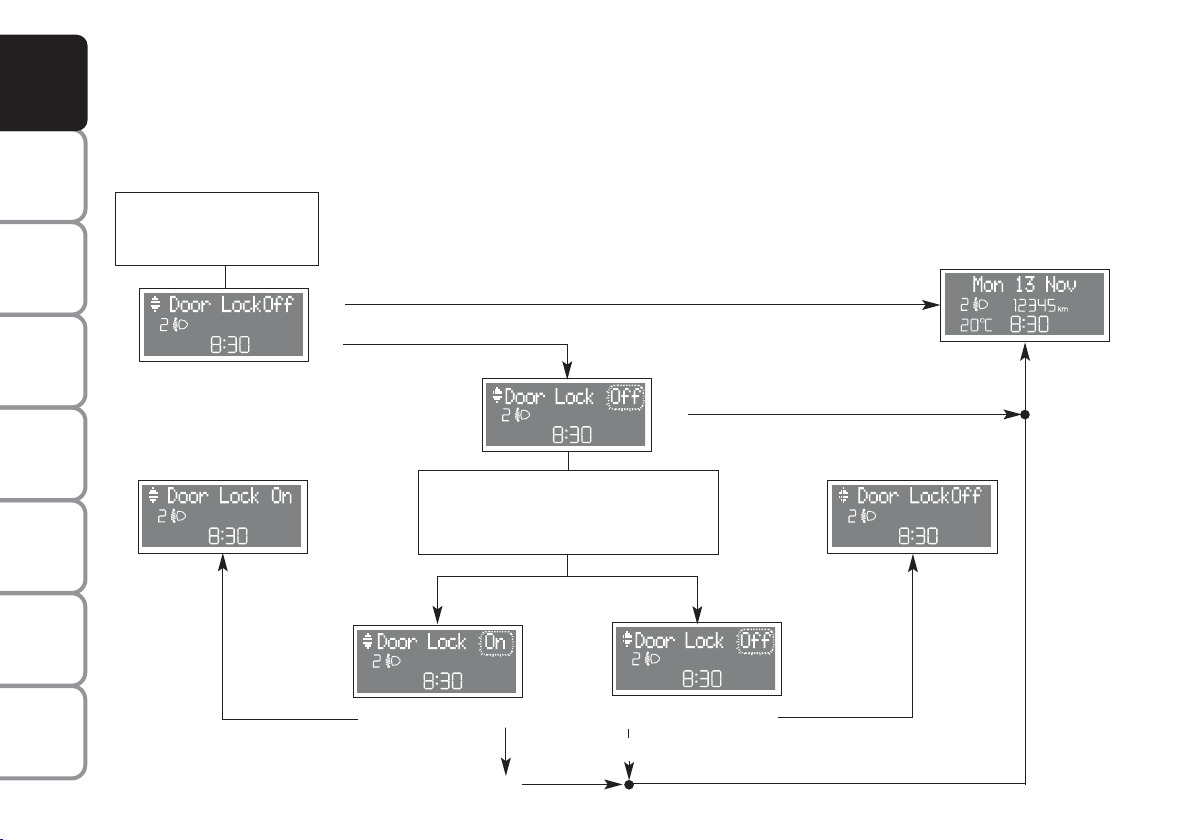
SPEEDLOCK (Door Lock) (where provided)
This function:
❒ when activated (ON) locks automatically the doors when the car speed exceeds 20 km/h;
❒ when deactivated (OFF) doesn’t perform automatic door lock when the car speed exceeds 20 km/h
See “Initial check”
and “Access to
menu screen”
+
–
Menu screen
R
Q
Return to previously
displayed
screen, e.g.:
R
Return to menu screen
+
Use buttons +/– to select ON/OFF.
Set selection flashes.
–
Return to menu screen
TECHNICAL
SPECIFICATIONS
INDEX
36
Q
Q
R
Q
R
Q
Page 38
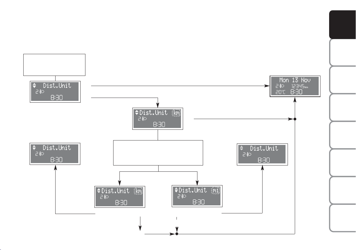
“DISTANCE UNIT” (Dist. Unit)
The display gives information according to the set unit (km or mi). To select the required distance units, proceed
as follows:
See “Initial check”
and “Access to
menu screen”
Return to previously
displayed
screen, e.g.:
AND
CONTROLS
DASHBOARD
SAFETY
DEVICES
+
–
Menu screen
Return to menu screen
R
Q
Q
Use buttons +/– to set the required
+
distance units (km or mi).
Set selection flashes.
–
Q
R
Q
R
R
Q
Return to menu screen
OF THE CAR
CORRECT USE
WARNING
LIGHTS AND
IN AN
EMERGENCY
CAR
MAINTENANCE
TECHNICAL
SPECIFICATIONS
INDEX
37
MESSAGES
Page 39

AND
CONTROLS
DASHBOARD
SAFETY
DEVICES
OF THE CAR
CORRECT USE
“CONSUMPTION UNIT” (Consump.)
This function enables to select the unit of measure for fuel consumption (km/l, l/100 km or mpg) according to the
previously set distance unit (km or mi, see previous paragraph “Distance unit”). To set this function proceed as
follows:
Menu screen
See “Initial check”
and “Access to
menu screen”
If setting km
+
–
R
Q
R
Return to
previously displayed
screen, e.g.:
WARNING
MESSAGES
LIGHTS AND
IN AN
EMERGENCY
CAR
MAINTENANCE
TECHNICAL
SPECIFICATIONS
INDEX
38
Return to menu
screen
If setting mi
Use buttons +/– to set the
+
fuel consumption unit km/l or l/100km.
–
Set selection flashes
Q
Q
R
Q
R
Q
R
Return to menu
screen
Q
Page 40

“TEMPERATURE UNIT” (Temp. Unit)
To select temperature unit (°C or °F), proceed as follows:
AND
CONTROLS
DASHBOARD
See “Initial check”
and “Access to
menu screen”
+
–
Menu screen
Return to menu screen
R
Q
Q
Use buttons +/– to select
+
the required temperature unit (°C or °F).
Set selection flashes.
–
Q
Q
R
R
R
Q
Return to previously
screen, e.g.:
Return to menu screen
displayed
SAFETY
DEVICES
OF THE CAR
CORRECT USE
WARNING
MESSAGES
LIGHTS AND
IN AN
EMERGENCY
CAR
MAINTENANCE
TECHNICAL
SPECIFICATIONS
INDEX
39
Page 41

AND
CONTROLS
DASHBOARD
SAFETY
DEVICES
OF THE CAR
CORRECT USE
WARNING
MESSAGES
LIGHTS AND
LANGUAGE (Lang.)
Display messages can be shown in different languages (Italian, Dutch, English, Spanish, French, Portuguese, German).
To select the required language proceed as follows:
Return to previously
displayed
screen, e.g.:
See “Initial check”
and “Access to
menu screen”
+
–
Menu screen
R
Q
R
–
–
–
IN AN
EMERGENCY
CAR
MAINTENANCE
TECHNICAL
SPECIFICATIONS
INDEX
40
Q
–
–
–
–
Q
Return to menu
screen
Page 42

BUZZER VOLUME (Buzzer Vol)
The volume of the buzzer accompanying any failure/warning indication can be adjusted according to 8 levels. The
buzzer can be adjusted and, in certain cases, it cannot be excluded. To adjust the volume proceed as follows:
AND
CONTROLS
DASHBOARD
See “Initial check”
and “Access to
menu screen”
+
–
Menu screen
Return to menu screen
R
Q
Q
Use buttons +/– to adjust
+
the buzzer volume.
–
Set selection flashes.
Q
R
Q
R
R
Q
Return to previously
screen, e.g.:
Return to menu screen
displayed
SAFETY
DEVICES
OF THE CAR
CORRECT USE
WARNING
MESSAGES
LIGHTS AND
IN AN
EMERGENCY
CAR
MAINTENANCE
TECHNICAL
SPECIFICATIONS
INDEX
41
Page 43

AND
CONTROLS
DASHBOARD
SAFETY
DEVICES
BUTTON VOLUME (Keys Volume)
The volume of the roger-beep accompanying the activation of certain buttons can be adjusted according to 8 levels.
The roger-beep can be adjusted and excluded. To adjust the volume proceed as follows:
See “Initial check”
and “Access to
menu screen”
Return to previously
displayed
screen, e.g.:
OF THE CAR
CORRECT USE
WARNING
MESSAGES
LIGHTS AND
IN AN
EMERGENCY
CAR
MAINTENANCE
TECHNICAL
SPECIFICATIONS
INDEX
42
+
–
Menu screen
Return to menu screen
R
Q
Q
Use buttons +/– to adjust
+
the roger-beep volume.
Set selection flashes.
–
Q
R
Q
R
R
Return to menu screen
Q
Page 44

SERVICE (Service)
Through the “Service” function it is possible to receive information connected with correct vehicle maintenance.
AND
CONTROLS
DASHBOARD
See “Initial check”
and “Access to
menu screen”
+
–
Menu screen
Return to previously
displayed
screen, e.g.:
Return to menu
screen
R
Q
Q
R
or
Use buttons + or – to select displaying
+
in km/days or mi/days according to the
–
“unit” set.
R
R
R
Q
Return to previously
Return to menu
screen
displayed
screen, e.g.:
continues
on next
page
SAFETY
DEVICES
OF THE CAR
CORRECT USE
WARNING
MESSAGES
LIGHTS AND
IN AN
EMERGENCY
CAR
MAINTENANCE
TECHNICAL
SPECIFICATIONS
INDEX
43
Page 45

AND
CONTROLS
DASHBOARD
SAFETY
DEVICES
OF THE CAR
CORRECT USE
WARNING
MESSAGES
LIGHTS AND
IN AN
EMERGENCY
CAR
MAINTENANCE
TECHNICAL
SPECIFICATIONS
INDEX
Return to menu
screen
Q
continues
from
previous
page
R
Return to previously
displayed
screen, e.g.:
R
Q
Return to menu
screen
The “Service schedule” includes vehicle maintenance every 20,000 km (or 12,000 mi) or every year; this is shown automatically, with the ignition key at MAR, starting from 2,000 km (or 1,240 miles) or 30 days from this deadline and it is shown again every 200 km (or 124 mi) or 3
days. For 1.3 Multijet versions, see “Car Maintenance” in section “Service schedule to change engine oil and filter and air cleaner. Below 200
km service indications are proposed at shorter intervals. Service intervals will be displayed in km or mi according to the unit set. When a programmed maintenance interval (coupon) is near to come, turning the ignition key to MAR, will display the message “Service” followed by the
number of km, or days to go before car servicing. “Scheduled servicing” message is displayed in km, miles or days according to the approaching service interval. Contact a Fiat Dealership to carry out any service operation provided by the “Service schedule” or “Annual inspection plan”,
and to reset the display.
44
Page 46

EXIT MENU (Exit Menu)
This is the last function that closes the circular setting cycle listed in the initial menu screen.
Menu screen
See “Initial check”
and “Access to
menu screen”
+
–
Use button – to return to Speed Lim.
screen (first Menu item).
R
Return to previously
displayed
screen, e.g.:
AND
CONTROLS
DASHBOARD
SAFETY
DEVICES
OF THE CAR
CORRECT USE
WARNING
MESSAGES
LIGHTS AND
IN AN
EMERGENCY
CAR
MAINTENANCE
TECHNICAL
INDEX
45
SPECIFICATIONS
Page 47

AND
CONTROLS
DASHBOARD
SAFETY
DEVICES
OF THE CAR
CORRECT USE
TRIP COMPUTER
The “Trip computer” displays information relating to the operating status of the car. This function comprises the
“General trip”, concerning the complete mission of the car and “Trip B”, concerning the partial car mission. This
function (as shown in the graph below) is contained within the complete mission. Both functions are resettable.
The “General trip” displays the figures relating to Range, Distance, Aver. Consumpt., Curr. consumpt., Avg. speed,
Traveltime. “Trip B” displays information concerning Distance B, Aver. Consump. B, Avg. speed B, Traveltime B
(driving time). The “Trip B” function can be excluded. Value selected will be displayed until new information is
requested.
Start of journey procedure (reset)
To start a new journey monitored by the “General trip”, with the key to MAR, press button
on right steering
{
column stalk with mode &(see “Control buttons”).
WARNING
MESSAGES
LIGHTS AND
IN AN
EMERGENCY
CAR
MAINTENANCE
TECHNICAL
SPECIFICATIONS
INDEX
46
Reset General Trip
End of complete mission - Start of new mission
˙
TRIP B
˙
Reset TRIP B
End of partial mission
Start of new partial mission
GENERAL TRIP
Reset TRIP B
˙
˙
End of partial mission
Start of new partial mission
Reset TRIP B
TRIP B
End of partial mission
Start of new partial mission
˙
Reset GENERAL TRIP
End of complete mission - Start of new mission
˙
TRIP B
˙
Reset TRIP B
End of partial mission
Start of new partial mission
˙
The reset operation in the presence of the screens concerning the “General trip” makes it possible to reset also the
“Trip B”. The reset operation in the presence of the screens concerning only the “Trip B” makes it possible to reset
only the information associated with this function.
IMPORTANT The “Range” information cannot be reset.
Page 48

“Trip computer” information are displayed according to the following diagram:
See “Initial check” and
“Access to menu screen”
AND
CONTROLS
DASHBOARD
SAFETY
DEVICES
Previously displayed
screen, e.g.:
% % %
(*)
(*)(*)
(*)
%
(*)
%
= “Reset General trip” and “Trip B” excluding
&
“Range to empty” (see paragraph “Reset General trip”).
%
(*)
continued from previous page
%
(*)
The two screens concerning a trip item
alternate three times, then the second
one stays on fixed on the display.
OF THE CAR
CORRECT USE
WARNING
LIGHTS AND
IN AN
EMERGENCY
CAR
MAINTENANCE
TECHNICAL
SPECIFICATIONS
INDEX
47
MESSAGES
Page 49

AND
CONTROLS
DASHBOARD
SAFETY
DEVICES
OF THE CAR
CORRECT USE
WARNING
MESSAGES
LIGHTS AND
continued from previous page
Trip B ON?
YES
Return to previously
displayed screen, e.g.:
NO
IN AN
EMERGENCY
CAR
MAINTENANCE
TECHNICAL
SPECIFICATIONS
INDEX
48
% % %
(*)
&
(*)
= “Reset Trip B”
(see paragraph “Reset Trip B”).
%
(*) (*)
Page 50

After resetting “Trip” by pressing the button with &mode, the following functions are displayed:
Reset GENERAL TRIP
= “Reset General trip” and “Trip B”
&
(excluding “Range to empty”).
Reset TRIP B
= “Reset Trip B”
&
AND
CONTROLS
DASHBOARD
SAFETY
DEVICES
OF THE CAR
CORRECT USE
WARNING
MESSAGES
LIGHTS AND
IN AN
EMERGENCY
CAR
MAINTENANCE
TECHNICAL
INDEX
49
SPECIFICATIONS
Page 51

AND
CONTROLS
DASHBOARD
SAFETY
DEVICES
OF THE CAR
CORRECT USE
WARNING
MESSAGES
LIGHTS AND
IN AN
EMERGENCY
CAR
MAINTENANCE
Range to empty = shows the distance in km (or
miles) that the car can still cover before needing fuel,
assuming that driving conditions are kept unvaried.
The display will show “- - - -” in the following cases:
❒ range lower than 50 km. In this event “- - - -” are
preceded by message “Warning Limited Range” (this
message will be displayed even if not in Trip
Computer mode);
❒ car parked with engine running for long time; when
restarting range indication will be displayed again.
Distance travelled = shows the km (or miles)
covered from the start of the new mission (*).
Average consumption = shows the average
consumption calculated from the start of the new
mission (*); this value can be expressed in km/l or
l/100 km or in mpg.
Instant consumption = shows fuel consumption
variation, this value is updated constantly. If the car is
parked with engine running the display will show “- - -
-“. When restarting the car, the instant consumption
indication will be displayed again.
Average speed = shows the average speed of the
car in relation with total time elapsed from the start of
the new mission (*).
Trip time = time elapsed from the start of the new
mission (*).
(*) New mission = starts from last reset:
– “manual” reset is performed by the driver by
pressing the relevant button (see paragraph
“Control buttons”)
– “automatic” reset is performed when the Distance
travelled reaches 9999.9 km or when Trip Time
reaches 99:59 (99 hours and 59 minutes)
– after reconnecting the battery.
IMPORTANT Lacking information, Trip computer
values are displayed with “- - - -”. When restoring
normal operating conditions after a failure, calculation
will restart regularly without resetting either previous
displayed values or the start of a new mission (*).
IMPORTANT After disconnecting/reconnecting the
battery, certain displayed values will be equal to
“- - - -” until significant data for recalculation are
available.
TECHNICAL
SPECIFICATIONS
INDEX
50
Page 52

INSTRUMENT PANEL, DISPLAY AND BUTTON LIGHTING ADJUSTMENT
(LIGHT RHEOSTAT)
With this function it is possible to adjust the lighting (dimming/brightening) of the instrument cluster, and two-zone
climate control display (where required).
To adjust proceed as follows:
AND
CONTROLS
DASHBOARD
SAFETY
DEVICES
See “Initial check”
and “Access to
menu screen”
Previously
displayed
screen, e.g.:
Use buttons +/– to carry out required
light adjustment.
+
–
Automatic return to standard screen
after few seconds or by
pressing button
Q
F0I0243m
OF THE CAR
CORRECT USE
+
–
WARNING
MESSAGES
LIGHTS AND
IN AN
EMERGENCY
CAR
MAINTENANCE
TECHNICAL
SPECIFICATIONS
INDEX
51
Page 53

AND
CONTROLS
DASHBOARD
SAFETY
DEVICES
OF THE CAR
CORRECT USE
WARNING
MESSAGES
LIGHTS AND
IN AN
EMERGENCY
SEATS
FRONT SEATS
Moving the seat backwards or forwards
Lift the lever (A) (on seat internal side) and push the seat forwards or
backwards: in the driving position the arms should rest on the rim of the
steering wheel.
F0I0044m
Seat height adjustment (where provided)
Move the lever (B) upwards or downwards to achieve the required
height.
IMPORTANT Adjustment must be carried out only seated in the driver’s
seat.
Back rest angle adjustment
Turn the knob (C).
CAR
MAINTENANCE
TECHNICAL
SPECIFICATIONS
INDEX
52
F0I0045m
Lumbar adjustment (where provided)
To adjust, turn the knob (D).
Page 54

Seat warming (where provided)
Press button (A) to switch the seat warming on/off.
The led on the button will light up when the function is on.
WARNING
Only make adjustments when the car is stationary.
F0I0049m
AND
CONTROLS
DASHBOARD
SAFETY
DEVICES
OF THE CAR
CORRECT USE
WARNING
MESSAGES
LIGHTS AND
IN AN
EMERGENCY
CAR
MAINTENANCE
WARNING
Once you have released the lever, check that the seat is firmly locked in the
runners by trying to move it back and forth. Failure to lock the seat in place
could result in the seat moving suddenly and the driver losing control
of the car.
TECHNICAL
INDEX
53
SPECIFICATIONS
Page 55
AND
A
DASHBOARD
SAFETY
CORRECT USE
WARNING
LIGHTS AND
IN AN
CAR
CONTROLS
DEVICES
OF THE CAR
MESSAGES
EMERGENCY
MAINTENANCE
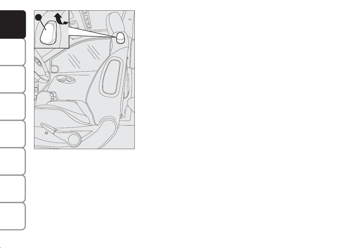
Tilting the back rest (3-door versions)
To gain access to the rear seats, pull the handle (A) upwards, the back
rest folds and the seat is free to run forwards.
When resetting the back rest, the seat returns to its original position
(mechanical memory).
Always check that the seat is firmly locked in the runners by trying to
move it back and forth.
F0I0075m
TECHNICAL
SPECIFICATIONS
INDEX
54
Page 56
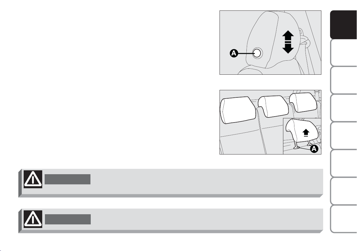
HEAD RESTRAINTS
FRONT SEATS
According to versions they can be fixed or adjustable in height.
To raise or lower the head restraint, press button (A) then move it to
the required position until hearing the locking click. Make sure it is
properly locked in place.
REAR SEATS (where provided)
According to versions, two or three head restraints can be provided.
To remove the head restraints, first remove the rear parcel shelf (see
paragraph “Extending the boot”), press button (A) set aside the two
supports and take them out.
Certain versions are fitted with three head restraints and central seat
with seat belt with three anchoring points and reel.
WARNING
Remember that the head restraints should be adjusted to support the back of
your head and not your neck. Only in this position do they exert their
protective action.
F0I0074m
F0I0136m
AND
CONTROLS
DASHBOARD
SAFETY
DEVICES
OF THE CAR
CORRECT USE
WARNING
MESSAGES
LIGHTS AND
IN AN
EMERGENCY
CAR
MAINTENANCE
TECHNICAL
SPECIFICATIONS
WARNING
To optimise head restraint protective action, adjust the seat back upright and
keep your head as close as possible to the head restraint.
INDEX
55
Page 57

STEERING WHEEL
A
AND
CONTROLS
DASHBOARD
SAFETY
DEVICES
OF THE CAR
CORRECT USE
WARNING
MESSAGES
LIGHTS AND
IN AN
EMERGENCY
CAR
MAINTENANCE
TECHNICAL
SPECIFICATIONS
INDEX
WARNING
WARNING
On certain versions the steering wheel can be adjusted in height.
Proceed as follows:
❒ move lever (A) to position (1);
❒ adjust the steering wheel;
❒ refit the lever to position (2) to stop the steering wheel.
F0I0046m
REARVIEW MIRRORS
DRIVING MIRROR
The mirror is fitted with a safety device that causes it to be released in
the event of a violent crash.
Using the lever (A) it can be moved to two different positions: normal or
antiglare.
F0I0047m
Any adjustment of the steering wheel position must be carried out only with the
car stationary and the engine turned off.
It is absolutely forbidden to carry out whatever after-market operation involving
steering system or steering column modifications (e.g.: installation of anti-theft
device) that could badly affect performance and safety, cause the lapse of
warranty and also result in non-compliance of the car with homologation
requirements.
56
Page 58
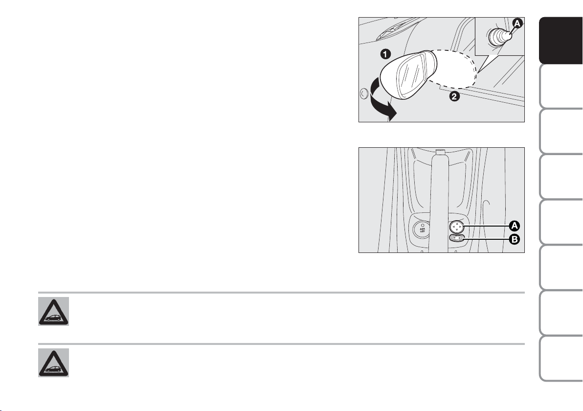
DOOR MIRRORS
Manual adjustment
From the passenger compartment, use knob (A) to make the required
adjustments. When required (for example when the mirror causes
difficulty in narrow spaces) it is possible to fold the mirror moving it from
position (1) to position (2).
Electrical adjustment (where provided)
This operation can be only performed with ignition key to MAR.
Proceed as follows:
❒ use switch (B) to select the mirror required (left or right);
❒ to adjust the mirror move (A) in the four directions;
IMPORTANT Any adjustment of the mirror position must be carried out
only with the car stationary and handbrake engaged.
When driving the mirrors shall always be in position (1).
F0I0048m
F0I0212m
AND
CONTROLS
DASHBOARD
SAFETY
DEVICES
OF THE CAR
CORRECT USE
WARNING
MESSAGES
LIGHTS AND
IN AN
EMERGENCY
CAR
MAINTENANCE
TECHNICAL
SPECIFICATIONS
As the driver’s door mirror is curved, it may slightly alter the perception of distance.
INDEX
57
Page 59
AND
CONTROLS
DASHBOARD
SAFETY
DEVICES
OF THE CAR
CORRECT USE
WARNING
MESSAGES
LIGHTS AND
IN AN
EMERGENCY
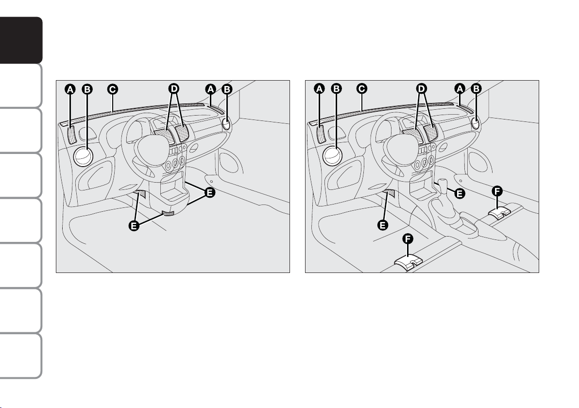
HEATING/CLIMATE CONTROL SYSTEM
Version with central dashboard unit Version with central tunnel unit
CAR
MAINTENANCE
TECHNICAL
SPECIFICATIONS
INDEX
58
F0I0217m F0I0189m
A - Fixed side vents - B - Adjustable side outlets - C Fixed upper vent - D - Fixed central vent - E - Lower
vents
A - Fixed side vents - B - Adjustable side outlets - C Fixed upper vent - D - Fixed central vent - E - Lower
vents - F - Lower vents for rear seats
Page 60
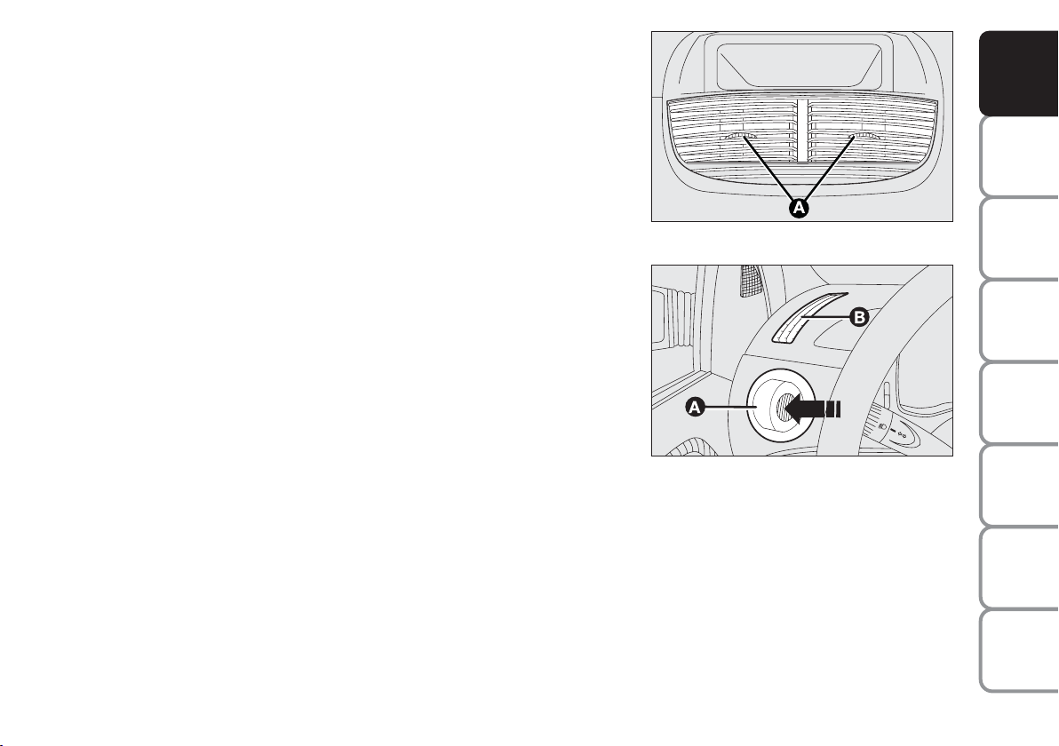
CENTRAL VENTS
(A) - Air flow opening/closing control.
SIDE OUTLETS AND VENTS
(A) - Adjustable outlet: press in the direction of the arrow as required.
(B) - Fixed vent for side windows.
F0I0250m
F0I0050m
AND
CONTROLS
DASHBOARD
SAFETY
DEVICES
OF THE CAR
CORRECT USE
WARNING
MESSAGES
LIGHTS AND
IN AN
EMERGENCY
CAR
MAINTENANCE
TECHNICAL
INDEX
59
SPECIFICATIONS
Page 61

AND
C
CONTROLS
DASHBOARD
SAFETY
DEVICES
OF THE CAR
CORRECT USE
WARNING
MESSAGES
LIGHTS AND
IN AN
EMERGENCY
CAR
MAINTENANCE
LOWER VENTS
(C) - (D) Fixed vents for conveying air to the footwell.
F0I0051m
F0I0232m
TECHNICAL
SPECIFICATIONS
INDEX
60
Page 62
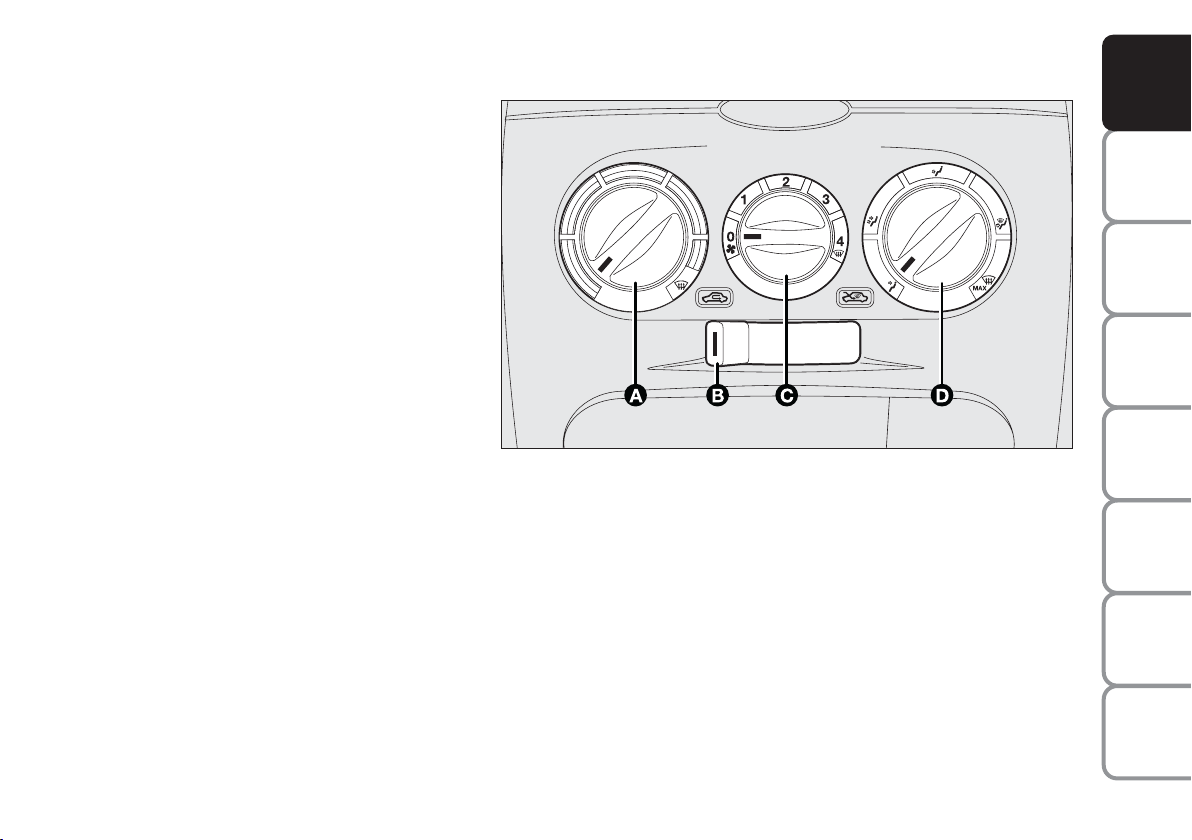
HEATING AND VENTILATION
CONTROLS
(A): Air temperature knob (mixing hot and
cold air)
(B): Air recirculation on/off button
(C): Fan knob
(D): Air distribution knob.
CLIMATIC COMFORT
Knob (D) directs the air inside the passenger
compartment according to five levels:
¥
air flow from central vents and side
outlets;
μ to warm the feet and keep the face cool
(“bilevel” function)
w to speed up passenger compartment
warming;
≤ to warm the passenger compartment and
at the same time demist the windscreen;
Z
to demist and defrost the windscreen and
side front windows.
HEATING
Proceed as follows:
-
❒ rotate knob (A) (pointer on
) completely to the right;
❒ turn knob (C) to the required speed;
❒ move knob (D) to:
≤ to warm the feet and at the same time demist the
windscreen;
μ
to warm the feet and convey cooler air from central vents
and dashboard outlets;
w for quick heating.
F0I0195m
AND
CONTROLS
DASHBOARD
SAFETY
DEVICES
OF THE CAR
CORRECT USE
WARNING
MESSAGES
LIGHTS AND
IN AN
EMERGENCY
CAR
MAINTENANCE
TECHNICAL
SPECIFICATIONS
INDEX
61
Page 63

AND
CONTROLS
DASHBOARD
SAFETY
DEVICES
OF THE CAR
CORRECT USE
WARNING
MESSAGES
LIGHTS AND
IN AN
EMERGENCY
CAR
MAINTENANCE
QUICK HEATING
Proceed as follows:
❒ close all dashboard vents;
-
w
;
-
.
;
❒ turn knob (A) to
❒ turn knob (C) to 4
❒ turn knob (D) to
QUICK WINDSCREEN AND FRONT SIDE
WINDOW DEMISTING/DEFROSTING
(MAX-DEF function)
Proceed as follows:
❒ turn knob (A) to
❒ turn knob (C) to 4
❒ turn knob (D) to
❒ slider (B) at
Y
-
Z
.
;
-
;
;
After demisting/defrosting, operate the controls to
restore the required comfort.
Preventive demisting procedure
In the event of considerable outside moisture and/or
rain and/or considerable differences in temperature
inside and outside the passenger compartment,
perform the following preventive demisting procedure:
Y
❒ slider (B) at
❒ turn knob (A) to
;
-
;
❒ turn knob (C) to 2;
Z
❒ turn knob (D) to
or to ≤if the windows do not
mist up.
REAR WINDOW AND DOOR MIRROR
DEMISTING/DEFROSTING (where required)
(
Press
to turn this function on.
Activation is indicated by the turning on of the warning
(
light
on the instrument panel.
This function is timed and switches off automatically
after 30 minutes. To cut out this function press again
(
button
.
IMPORTANT Do not apply stickers on the inside of
the rear window over the heating filaments to avoid
damage that might cause it to stop working properly.
TECHNICAL
SPECIFICATIONS
INDEX
62
Page 64

FAN SPEED ADJUSTMENT
Proceed as follows:
❒ open completely central vents and side outlets;
❒ turn knob (A) to the blue sector;
Y
❒ slider (B) at
;
❒ turn knob (C) to the required speed;
¥
❒ turn knob (D) to
.
RECIRCULATION
T
Move slider (B) to
.
This function is particularly useful when the outside air
is heavily polluted (in a traffic jam, tunnel, etc.).
However, it is better not to use it for long periods,
especially if there are several people in the car.
IMPORTANT The inside air recirculation system
makes it possible to reach the required “heating” or
“cooling” conditions faster. Do not use the air
recirculation function on rainy/cold days as it would
considerably increase the possibility of the windows
misting inside.
AND
CONTROLS
DASHBOARD
SAFETY
DEVICES
OF THE CAR
CORRECT USE
WARNING
MESSAGES
LIGHTS AND
IN AN
EMERGENCY
CAR
MAINTENANCE
TECHNICAL
INDEX
63
SPECIFICATIONS
Page 65
AND
A B C D
CONTROLS
DASHBOARD
SAFETY
DEVICES
OF THE CAR
CORRECT USE
WARNING
MESSAGES
LIGHTS AND
IN AN
EMERGENCY
CAR
MAINTENANCE
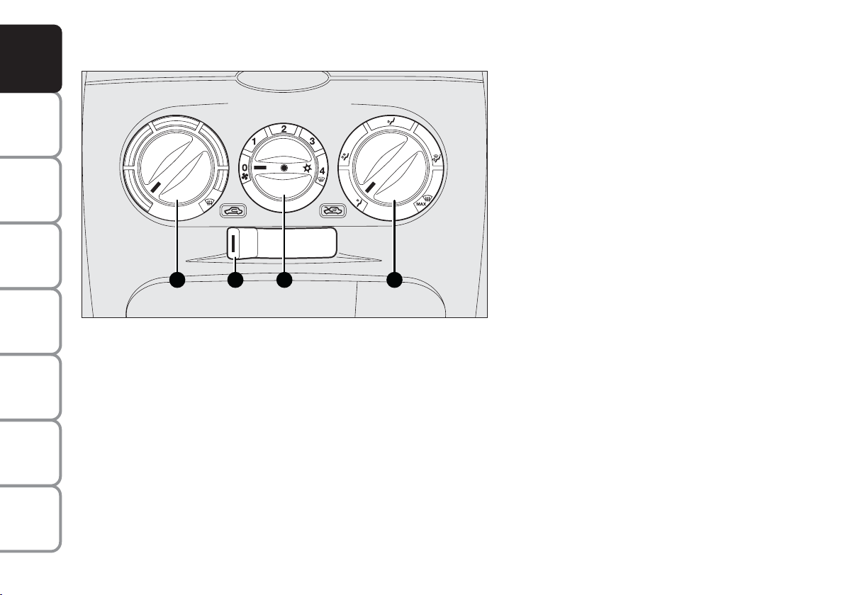
MANUAL CLIMATE CONTROL SYSTEM (where provided)
CLIMATIC COMFORT
Knob (D) directs the air inside the passenger
compartment according to five levels:
¥
air flow from central vents and side
outlets;
μ
to warm the feet and keep the face cool
(“bilevel” function)
w
to speed up passenger compartment
warming;
≤ to warm the passenger compartment and
at the same time demist the windscreen;
Z
to demist and defrost the windscreen and
side front windows.
F0I0131m
CONTROLS
(A): Air temperature knob (mixing hot and cold air);
(B): Air recirculation on/off button;
(C): Fan knob and climate control system on/off;
(D): Air distribution knob.
TECHNICAL
SPECIFICATIONS
INDEX
64
Page 66

HEATING
Proceed as follows:
-
❒ rotate knob (A) (pointer on
) completely to the
right;
❒ turn knob (C) to the required speed;
❒ move knob (D) to:
≤ to warm the feet and at the same time demist the
windscreen;
μ
to warm the feet and convey cooler air from
central vents and dashboard outlets;
w
for quick heating.
QUICK HEATING
Proceed as follows:
❒ close all dashboard vents;
-
μ
;
-
.
;
❒ turn knob (A) to
❒ turn knob (C) to 4
❒ turn knob (D) to
QUICK WINDSCREEN AND FRONT SIDE
WINDOW DEMISTING/DEFROSTING
(MAX-DEF function)
Proceed as follows:
-
❒ turn knob (A) to
❒ turn knob (C) to 4
❒ turn knob (D) to
❒ slider (B) at
Y
;
-
;
Z
;
.
After demisting/defrosting, operate the controls to
restore the required comfort.
IMPORTANT Climate control system is very useful to
speed up demisting since it dehumidifies the air. Set
controls to demisting function as described previously
and switch on the climate control system by pressing
knob (C).
AND
CONTROLS
DASHBOARD
SAFETY
DEVICES
OF THE CAR
CORRECT USE
WARNING
MESSAGES
LIGHTS AND
IN AN
EMERGENCY
CAR
MAINTENANCE
TECHNICAL
INDEX
65
SPECIFICATIONS
Page 67

AND
CONTROLS
DASHBOARD
SAFETY
DEVICES
OF THE CAR
CORRECT USE
WARNING
MESSAGES
LIGHTS AND
IN AN
EMERGENCY
CAR
MAINTENANCE
Preventive demisting procedure
In the event of considerable outside moisture and/or
rain and/or considerable differences in temperature
inside and outside the passenger compartment,
perform the following preventive demisting procedure:
Y
❒ slider (B) at
❒ turn knob (A) to
;
-
;
❒ turn knob (C) to 2;
Z
❒ turn knob (D) to
or to ≤if the windows do not
mist up.
REAR WINDOW AND DOOR MIRROR
DEMISTING/DEFROSTING (where required)
(
Press
to turn this function on.
Activation is indicated by the turning on of the warning
(
light
on the instrument panel.
This function is timed and switches off automatically
after 30 minutes. To cut out this function press again
(
button
.
IMPORTANT Do not apply stickers on the inside of
the rear window over the heating filaments to avoid
damage that might cause it to stop working properly.
FAN SPEED ADJUSTMENT
Proceed as follows:
❒ open completely central vents and side outlets;
❒ turn knob (A) to the blue sector;
Y
❒ slider (B) at
;
❒ turn knob (C) to the required speed;
¥
❒ turn knob (D) to
;
RECIRCULATION
T
Move slider (B) to
.
This function is particularly useful when the outside air
is heavily polluted (in a traffic jam, tunnel, etc.).
However, it is better not to use it for long periods,
especially if there are several people in the car.
IMPORTANT The inside air recirculation system
makes it possible to reach the required “heating” or
“cooling” conditions faster. Do not use the air
recirculation function on rainy/cold days as it would
considerably increase the possibility of the windows
misting inside.
TECHNICAL
SPECIFICATIONS
INDEX
66
Page 68

CLIMATE CONTROL (cooling)
Proceed as follows:
❒ turn knob (A) to the blue sector;
-
❒ turn knob (C) to 4
❒ slider (B) at
T
❒ turn knob (D) to
;
;
¥
;
❒ press knob (C).
LOOKING AFTER THE SYSTEM
During the winter, the climate control system must be
turned on at least once a month for about ten
minutes. Before summer, have the system checked at a
Fiat Dealership.
AND
CONTROLS
DASHBOARD
SAFETY
DEVICES
Cooling adjustment
Proceed as follows:
Y
❒ slider (B) at
;
❒ Turn knob (A) to the right to raise temperature;
❒ Turn knob (C) to the left to reduce the fan speed.
OF THE CAR
CORRECT USE
WARNING
LIGHTS AND
IN AN
EMERGENCY
CAR
MAINTENANCE
TECHNICAL
SPECIFICATIONS
INDEX
67
MESSAGES
Page 69

EXTERNAL LIGHTS
AND
CONTROLS
DASHBOARD
SAFETY
DEVICES
OF THE CAR
CORRECT USE
WARNING
MESSAGES
LIGHTS AND
IN AN
EMERGENCY
CAR
MAINTENANCE
TECHNICAL
SPECIFICATIONS
F0I0065m
F0I0066m
The left-hand stalk controls the external lights and the direction
indicators.
The external lights can only be switched on when the ignition key is at
MAR.
SIDELIGHTS
6
Turn the knurled ring to
.
The warning light 3on the instrument cluster will come on.
DIPPED BEAM HEADLIGHTS
2
Turn the knurled ring to
The warning light
3
.
on the instrument cluster will come on.
With dipped beam and front fog lights on, turning on the main beam
headlights will turn off automatically the dipped beam headlights.
MAIN BEAM HEADLIGHTS
2
When the knurled ring is at
push the lever towards the dashboard
(stable position).
1
The warning light
on the instrument cluster will come on.
Pulling the lever towards the steering wheel again, the main beams are
turned off and the dipped beams on.
INDEX
68
F0I0067m
Page 70

FLASHING THE HEADLIGHTS
Pull the lever towards the steering wheel (unstable position) regardless of
the position of the knurled ring.
1
Instrument panel warning light
will turn on.
AND
CONTROLS
DASHBOARD
DIRECTION INDICATORS
Push the lever to stable position:
❒ up (position 1): engage the right-hand direction indicator;
❒ down (position 2): engage the left-hand direction indicator.
Î
Warning light
or ¥will come on flashing on the instrument cluster at
the same time.
Indicators are switched off automatically when the steering wheel is
straightened.
If you want the indicator to flash briefly to show that you are about to
change lane, move the stalk up or down without clicking into position
(unstable position). When released the stalk will return to its home
position.
F0I0068m
F0I0069m
SAFETY
DEVICES
OF THE CAR
CORRECT USE
WARNING
MESSAGES
LIGHTS AND
IN AN
EMERGENCY
CAR
MAINTENANCE
TECHNICAL
SPECIFICATIONS
INDEX
69
Page 71

AND
CONTROLS
DASHBOARD
SAFETY
DEVICES
OF THE CAR
CORRECT USE
WARNING
MESSAGES
LIGHTS AND
F0I0068m
“FOLLOW ME HOME” DEVICE
This function allows the illumination of the space in front of the car.
Activation
With the ignition key at STOP or removed, pull the left-hand stalk
towards the steering wheel and operate it within 2 minutes from when
the engine is turned off.
At each single movement of the stalk, the staying on of the lights is
extended by 30 seconds up to a maximum of 3,5minutes, then the lights
are switched off automatically.
Each time the lever is operated, the instrument panel warning light
3
turns on and the display will show the function activation time.
3
The warning light
will turn on the first time the stalk is operated and
it will stay on until the function is automatically deactivated. Each stalk
operation will just extend the staying on of the lights.
IN AN
EMERGENCY
CAR
MAINTENANCE
TECHNICAL
SPECIFICATIONS
INDEX
70
Deactivation
Keep the stalk pulled towards the steering wheel for more than 2
seconds.
Page 72

WINDOW WASHING
WINDSCREEN WASHER/WIPER
This device can only work when the ignition key is at MAR.
The stalk can be moved to five different positions:
(A): windscreen wiper off
(B): flick wipe: on certain versions, turning the knurled ring (F), four
possible intermittent speeds are obtained (slowest to fastest).
With the stalk in position (B), turning the knurled ring (F), four possible
intermittent speeds are obtained:
■
= very slow intermittent
■■
= slow intermittent
■■■
= intermittent medium
■■■■
= fast intermittent
(C): continuous slow;
(D): continuous fast;
(E): fast temporary (unstable position).
Operation in position (E) is limited to the time the lever is held in this
position. When the lever is released, it returns to position (A)
automatically stopping the wiper.
F0I0096m
AND
CONTROLS
DASHBOARD
SAFETY
DEVICES
OF THE CAR
CORRECT USE
WARNING
MESSAGES
LIGHTS AND
IN AN
EMERGENCY
CAR
MAINTENANCE
TECHNICAL
SPECIFICATIONS
71
INDEX
Page 73
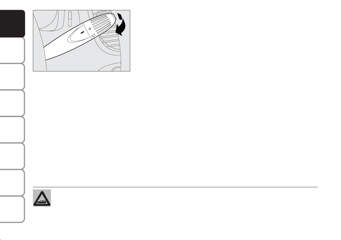
AND
,
CONTROLS
DASHBOARD
SAFETY
DEVICES
OF THE CAR
CORRECT USE
WARNING
MESSAGES
LIGHTS AND
IN AN
EMERGENCY
CAR
MAINTENANCE
F0I0159m
“Smart washing” function
Pulling the stalk towards the steering wheel (unstable position) operates
the windscreen washer; indeed, the latter comes into action
automatically if the stalk is pulled for more than half a second.
The wiper stops working three strokes after releasing the stalk. On
certain versions a further “cleaning stroke”, after a few seconds,
completes the wiping operation.
Operating the stalk quickly and repeatedly (for less than half a second) it
is possible to wet the windscreen several times without operating the
wiper.
TECHNICAL
SPECIFICATIONS
INDEX
72
Never use the window wiper to remove ice or snow from the windscreen.
In these conditions, the wiper is submitted to excessive effort that results in motor protection
cutting in and wiper operation inhibition for few seconds as a consequence. If operation is not
restored contact Fiat Dealership.
Page 74

RAIN SENSOR (where provided)
The rain sensor is behind the driving mirror in contact with the
windscreen and has the purpose of automatically adjust, during the
intermittent operation, the frequency of the windscreen wiper strokes as
to the rain intensity.
The sensor has a range of adjustment that gradually varies between wiper
stationary (no wiping) when the windscreen is dry, to wiper at first
continuous speed (continuous slow) with heavy rain.
Activation
Move the right-hand stalk downwards by one position.
The activation of the rain sensor is signalled by a control acquisition
“stroke”.
IMPORTANT Keep clean the glass in the sensor area.
Turning the knurled ring (F) it is possible to increase the sensitivity of the
rain sensor, obtaining a quicker change from stationary (no wiping) when
the windscreen is dry, to first continuous speed (continuous, slow).
The increase of the sensitivity of the rain sensor is signalled by a control
and acquisition “cycle”.
Operating the windscreen washer with the rain sensor activated the
normal washing cycle is performed at the end of which the rain sensor
resumes its normal automatic function.
F0I0077m
AND
CONTROLS
DASHBOARD
SAFETY
DEVICES
OF THE CAR
CORRECT USE
WARNING
MESSAGES
LIGHTS AND
IN AN
EMERGENCY
CAR
MAINTENANCE
F0I0096m
TECHNICAL
INDEX
73
SPECIFICATIONS
Page 75

AND
CONTROLS
DASHBOARD
SAFETY
DEVICES
OF THE CAR
CORRECT USE
WARNING
MESSAGES
LIGHTS AND
IN AN
EMERGENCY
CAR
MAINTENANCE
Deactivation
Turn the ignition key to STOP.
At the following starting operation (key at MAR), the
sensor will not be reactivated even is the stalk is on
(B). In this event, to activate the rain sensor, you have
to move the stalk to (A) or (C) and then again to (B).
When the rain sensor is again activated in this way, at
least one windscreen wiper stroke occurs, even if the
windscreen is dry.
Do not activate the rain sensor when washing the car in an automatic washing station.
In the event of ice on the windscreen, make sure to have disconnected the device.
The rain sensor is able to recognize and automatically
adjust itself in the presence of the following particular
conditions:
❒ impurities on the controlled surface (salt, dirt, etc.);
❒ straks of water caused by worn wiper blades;
❒ difference between day and night.
TECHNICAL
SPECIFICATIONS
INDEX
74
WARNING
Make sure the device is off when cleaning the windscreen.
Page 76

REAR WINDOW WASH/WIPE FUNCTION
,
This device can only work when the ignition key is at MAR.
To switch the rear window wiper on, turn the knurled ring from O to
'
. To wash the window push the stalk towards the dashboard.
On certain versions the rear window and windscreen wiping strokes are
synchronised.
AND
CONTROLS
DASHBOARD
SAFETY
DEVICES
“Smart washing” function
On certain versions, pulling the stalk towards the dashboard, with just
one movement it is possible to operate the washer jet and the wiper at
the same time; indeed, the latter comes into action automatically if the
stalk is pulled for more than half a second.
The wiper stops working three strokes after releasing the stalk. On
certain versions a further “cleaning stroke”, after a few seconds,
completes the wiping operation.
HEADLIGHT WASHERS
They are activated automatically when the windscreen washer is
operated with dipped beam headlights or main beam headlights on.
IMPORTANT Regularly check that the spray jets are intact and clean.
Never use the rear window wiper to remove ice or snow
from the rear window. In these conditions, the wiper is
submitted to excessive effort that results in motor
protection cutting in and wiper operation inhibition for few
seconds as a consequence. If operation is not restored
contact Fiat Dealership.
F0I0157m
F0I0158m
F0I0207m
OF THE CAR
CORRECT USE
WARNING
LIGHTS AND
IN AN
EMERGENCY
CAR
MAINTENANCE
TECHNICAL
SPECIFICATIONS
INDEX
75
MESSAGES
Page 77
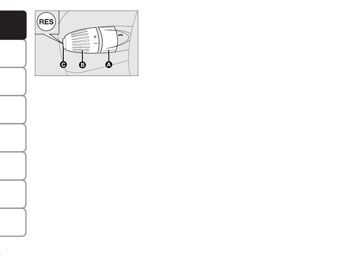
CRUISE CONTROL (where provided)
Î
Î
O
FF
ON
AND
CONTROLS
DASHBOARD
SAFETY
DEVICES
OF THE CAR
CORRECT USE
WARNING
MESSAGES
LIGHTS AND
IN AN
EMERGENCY
CAR
MAINTENANCE
TECHNICAL
SPECIFICATIONS
INDEX
It is a device able to support the driver, with electronic control, which
allows driving at speed over 30 km/h on long and straight dry roads (e.g.:
motorways), at a desired speed, without pressing the accelerator pedal.
Therefore it is not suggested to use this device on extra-urban roads
with traffic. Do not use it in town.
DEVICE ENGAGEMENT
F0I0156m
Turn knurled ring (A) to ON.
The device may only be engaged in the 4th or 5th or 6th gear. Travelling
downhill with the device engaged, the car speed may increase more than
the memorised one.
Ü
When the device is activated, the warning light
on the instrument
cluster turns on together with the message on the reconfigurable
multifunction display (where provided) (see section “Warning lights and
messages”).
76
Page 78

TO MEMORISE SPEED
Proceed as follows:
❒ turn the knurled ring (A) to ON and press the
accelerator pedal to the required speed;
❒ turn the knurled ring (B) to (+) for at least three
seconds, then release it. The car speed is
memorised and it is therefore possible to release
the accelerator pedal.
In the case of need (when overtaking for instance)
acceleration is possible simply pressing the accelerator
pedal; later, releasing the accelerator pedal, the car
will return to the speed memorised previously.
TO RESET THE MEMORISED SPEED
If the device has been disengaged for example pressing
the brake or clutch pedal, the memorised speed can
be reset as follows:
❒ accelerate gradually until reaching a speed
approaching the one memorised;
❒ engage the gear selected at the time of speed
memorising (4th or 5th or 6th gear);
❒ press the RES button (C).
TO INCREASE THE MEMORISED SPEED
The speed memorised can be increased in two ways:
❒ pressing the accelerator and then memorising the
new speed reached;
or
❒ momentaneously turning the ring (B) to (+).
Each pulse of the ring will correspond to a slight
increase in speed (about 1 km/h), while pressing
continuously will correspond to a continuous speed
increase.
AND
CONTROLS
DASHBOARD
SAFETY
DEVICES
OF THE CAR
CORRECT USE
WARNING
MESSAGES
LIGHTS AND
IN AN
EMERGENCY
CAR
MAINTENANCE
TECHNICAL
INDEX
77
SPECIFICATIONS
Page 79
AND
CONTROLS
DASHBOARD
SAFETY
DEVICES
OF THE CAR
CORRECT USE
WARNING
MESSAGES
LIGHTS AND
IN AN
EMERGENCY
CAR
MAINTENANCE
TO REDUCE MEMORISED SPEED
The speed memorised can be increased in two ways:
❒ disengaging the device and then memorising the new
speed;
or
❒ keeping the ring (B) pressed at (–) until reaching the
new speed which will be memorised automatically.
Each pulse of the ring will correspond to a slight
reduction in speed (about 1 km/h), while pressing
continuously will correspond to a continuous speed
reduction.
WARNING
When travelling with the device on, do not put the gearbox lever in neutral and do
not shift the Dualogic gearbox lever (where provided) to (N).
DEVICE DISENGAGEMENT
Turn the ring (A) to OFF or the ignition key to STOP.
The device is automatically deactivated also in one of
the following cases:
❒ pressing the brake or clutch pedal;
❒ ESP or ASR systems cut-in (where provided);
❒ gearshifting in versions with Dualogic automatic
transmission (where provided);
❒ unvoluntarily moving the Dualogic lever (where
provided) to (N).
TECHNICAL
SPECIFICATIONS
INDEX
78
WARNING
In the event of device malfunction or failure, turn the knurled ring (A) to OFF and
contact a Fiat Dealership after checking the protective fuse integrity.
Page 80
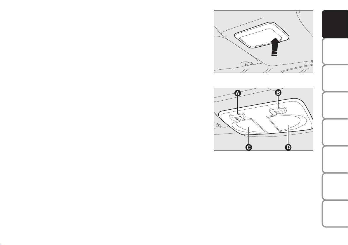
CEILING LIGHTS
FRONT CEILING LIGHT
With toggling lens
The light will come on automatically when a front door is opened and go
out when the door is closed.
Press the short side of the lens to switch the light on and off when the
doors are closed, as shown in the figure.
With map reading lights
Press switch (A) to switch the light on and off.
Switch (B) operates the map reading light.
With switch (A) in central position, lights (C) and (D) will come on/off
when doors are opened/closed.
With switch (A) pressed to the left, lights (C) and (D) are off and they
will not come on when doors are opened.
With switch (A) pressed to the right, lights (C) and (D) will come on
regardless of the position of the doors.
On certain versions, lights come on/off gradually.
With light off, switch (B) turn on the following lights:
❒ map reading light (C) if pressed to the left;
❒ map reading light (D) if pressed to the right.
IMPORTANT Make sure that both switches are in central position
before getting out of the car. This ensures that lights go out when the
doors are closed preventing the battery from running down.
F0I0088m
F0I0089m
AND
CONTROLS
DASHBOARD
SAFETY
DEVICES
OF THE CAR
CORRECT USE
WARNING
MESSAGES
LIGHTS AND
IN AN
EMERGENCY
CAR
MAINTENANCE
TECHNICAL
SPECIFICATIONS
INDEX
79
Page 81

AND
CONTROLS
DASHBOARD
SAFETY
DEVICES
OF THE CAR
CORRECT USE
WARNING
MESSAGES
LIGHTS AND
IN AN
EMERGENCY
CAR
MAINTENANCE
Ceiling light timing
Two timing strategies are available on certain versions,
in order to facilitate getting in and out of the car,
especially at night in dark areas.
Timing for getting into the car
The ceiling lights will come on as follows:
❒ for about 10 seconds when the front doors are
unlocked;
❒ for about 3 minutes when one of the side doors is
opened;
❒ for about 10 seconds when a door is closed (within
the three minutes).
Timing will be stopped when the ignition key is turned
to MAR.
Timing for getting out of the car
The ceiling lights will come on as follows when the key
is removed from the ignition switch:
❒ for about 10 seconds within two minutes after
stopping the engine;
❒ for about 3 minutes when one of the side doors is
opened;
❒ for about 7 minutes when a door is closed (within
the three minutes).
The timeout will automatically end when the doors are
locked.
TECHNICAL
SPECIFICATIONS
INDEX
80
Page 82
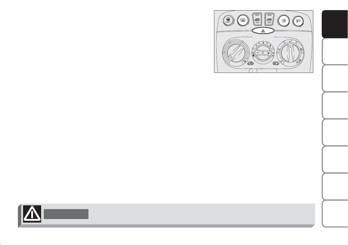
CONTROLS
HAZARD LIGHTS
r
They come on when switch
the ignition key.
When the device is on, the switch is flashing and warning lights
on the cluster come on.
Press the switch again to turn the lights off.
FRONT FOG LIGHTS (where provided)
5
Press button
; to activate these lights it is necessary to have the
side/taillights switched on and warning light 5on the cluster come on.
Press the button again to turn these lights off.
REAR FOG LIGHT
4
Press button
; to activate this light it is necessary to have the dipped
beam headlights switched onand warning light 4on the cluster come on.
Press the button again to turn these lights off.
HEATED REAR WINDOW
(
Press button
to turn it on. The device is automatically switched off
after about 20 minutes.
is pressed regardless of the position of
Î
and
¥
F0I0076m
AND
CONTROLS
DASHBOARD
SAFETY
DEVICES
OF THE CAR
CORRECT USE
WARNING
MESSAGES
LIGHTS AND
IN AN
EMERGENCY
CAR
MAINTENANCE
WARNING
The use of hazard lights is governed by the Road Traffic Code of the country you
are in. Keep to the rules.
TECHNICAL
INDEX
81
SPECIFICATIONS
Page 83

AND
CONTROLS
DASHBOARD
SAFETY
DEVICES
OF THE CAR
CORRECT USE
WARNING
MESSAGES
LIGHTS AND
IN AN
EMERGENCY
CAR
MAINTENANCE
FUEL CUT-OFF SWITCH (FIS)
It is located under the dashboard on the front right-hand door pillar and
it comes into operation in the case of an accident to block the supply of
fuel thereby stopping the engine.
Carefully inspect the car to find fuel leaks, e.g. in the engine
compartment, under the car or near the tank.
If no fuel leaks are found and the car can be started again, press button
(A) to reset the fuel system and the lights.
F0I0081m
After a crash, remember to turn the ignition key to STOP to prevent
battery run-down.
TECHNICAL
SPECIFICATIONS
INDEX
82
WARNING
If, after a crash, you smell fuel or see leaks from the fuel system, do not reset the
switch to avoid fire risk.
Page 84
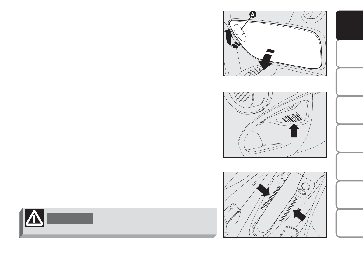
INTERIOR FITTINGS
GLOVE COMPARTMENT
Operate handle (A) as shown by the arrow to open the compartment.
COIN TRAY
A coin tray may be found on the dashboard on the central tunnel
according to the versions.
F0I0079m
AND
CONTROLS
DASHBOARD
SAFETY
DEVICES
OF THE CAR
CORRECT USE
WARNING
MESSAGES
LIGHTS AND
MAGNETIC CARD/TICKET SLOTS
The slots for holding magnetic cards and tickets (phone card, toll slips,
etc.) can be found on the central tunnel unit.
WARNING
Do not travel with the glove compartment
open: risk of passengers’ injury in case of
accident.
F0I0086m
F0I0087m
IN AN
CAR
TECHNICAL
INDEX
83
EMERGENCY
MAINTENANCE
SPECIFICATIONS
Page 85

AND
CONTROLS
DASHBOARD
SAFETY
DEVICES
OF THE CAR
CORRECT USE
WARNING
MESSAGES
LIGHTS AND
IN AN
EMERGENCY
CAR
MAINTENANCE
F0I0197m
F0I0080m
CIGAR LIGHTER
Press button (A) with ignition key at MAR.
After approx. 15 seconds it will return to its initial position and is ready
for use.
IMPORTANT Always check that the cigar lighter has turned off.
IMPORTANT The cigar lighter gets very hot. Handle it with care and
make sure that it is not used by children: danger of fire and/or burns.
ASHTRAY
For front passengers
Pull the flap towards yourself. Remove the ashtray (B) by pulling it
upwards as shown by the arrow for emptying it.
For rear passengers
For rear passengers there is a concealed ashtray set on the central
console.
Pull it as shown by the arrows for use and removal.
IMPORTANT Do not use the ashtray as waste paper basket: it might set
on fire in contact with cigarettes stub.
Non smokers can remove both the front and rear ashtrays and use the
handy oddment compartment which results.
TECHNICAL
SPECIFICATIONS
INDEX
84
F0I0052m
Page 86

SUN VISORS
They are located at the sides of the driving mirror. They can be adjusted
forwards and sidewards (this last adjustment is not possible on versions
fitted with Front window bag).
A courtesy mirror is applied to the back of the passenger’s side sun visor.
On some versions, the driver’s sun visor is fitted on the back with a
courtesy mirror: Lift the lid (A) to use the mirror.
AND
CONTROLS
DASHBOARD
SAFETY
DEVICES
REAR SIDE WINDOWS (three door versions)
The windows open outwards:
❒ move the lever as shown in the figure;
❒ push the lever outwards to open the window completely;
❒ push the lever back until it clicks.
To close the windows, pull the lever to the opposite direction until it
clicks.
F0I0082m
F0I0083m
OF THE CAR
CORRECT USE
WARNING
LIGHTS AND
IN AN
EMERGENCY
CAR
MAINTENANCE
TECHNICAL
SPECIFICATIONS
INDEX
85
MESSAGES
Page 87
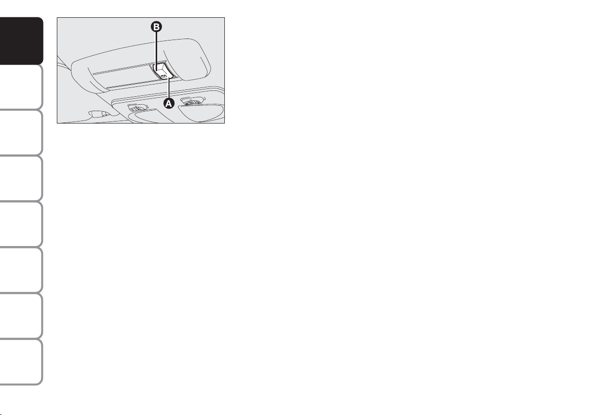
SUNROOF (where provided)
AND
CONTROLS
DASHBOARD
SAFETY
DEVICES
OF THE CAR
CORRECT USE
WARNING
MESSAGES
LIGHTS AND
IN AN
EMERGENCY
CAR
MAINTENANCE
TECHNICAL
SPECIFICATIONS
F0I0084m
It is controlled electrically and it will only work when the ignition key is
at MAR.
Sunroof is controlled by a switch. When you release it the roof locks in
the position it is at that moment.
SUNROOF OPENING
Full opening
Press switch to (A) (symbol).
“Spoiler” position
Press switch to (B), this is only possible when the roof is closed.
SUNROOF CLOSING
Press switch to (B). Press to (A) (symbol) when the roof is in spoiler
position.
A sliding sunshade is fitted to lessen the effect of sun rays in the
passenger compartment.
INDEX
86
Page 88

EMERGENCY OPERATION
If the switch does not work, the sunroof can be operated manually as
follows:
❒ remove (A) operating from points (B) shown by the arrows;
❒ insert the screwdriver provided into (C);
❒ when fully open, turn the screwdriver half a turn back until it clicks,
then remove the screwdriver.
Do not open the sunroof if there is snow or ice on it: it could be damaged.
F0I0085m
F0I0094m
AND
CONTROLS
DASHBOARD
SAFETY
DEVICES
OF THE CAR
CORRECT USE
WARNING
MESSAGES
LIGHTS AND
IN AN
EMERGENCY
CAR
MAINTENANCE
WARNING
When leaving the car, the ignition key should be removed to prevent the sunroof
from being operated inadvertently and harming anyone remaining in the car.
Improper use of the sunroof can be dangerous. Before and during its operation
ensure that any passengers are not at risk from the moving roof either by
personal objects getting caught in the mechanism or by being injured by it
directly.
TECHNICAL
INDEX
87
SPECIFICATIONS
Page 89

AND
CONTROLS
DASHBOARD
SAFETY
DEVICES
OF THE CAR
CORRECT USE
WARNING
MESSAGES
LIGHTS AND
IN AN
EMERGENCY
CAR
MAINTENANCE
DOORS
CENTRAL DOOR LOCKING SYSTEM
From the outside
With the doors closed, fit and turn the key in one of
the front door locks.
From the inside
With the doors closed, press (to lock) or lift (to
unlock) one of the front door knobs.
The rear door knobs will lock or unlock only the
specific door.
IMPORTANT If one of the doors is not shut properly
or there is a failure in the system, the central locking
feature will cut out and after some attempts the device
stops working for about two minutes. In these 2
minutes, the doors can be locked or unlocked
manually. After the two minutes, the control unit is
ready to receive commands once more.
If the cause of the failure is removed, the device will
start working properly.
TECHNICAL
SPECIFICATIONS
INDEX
88
Page 90
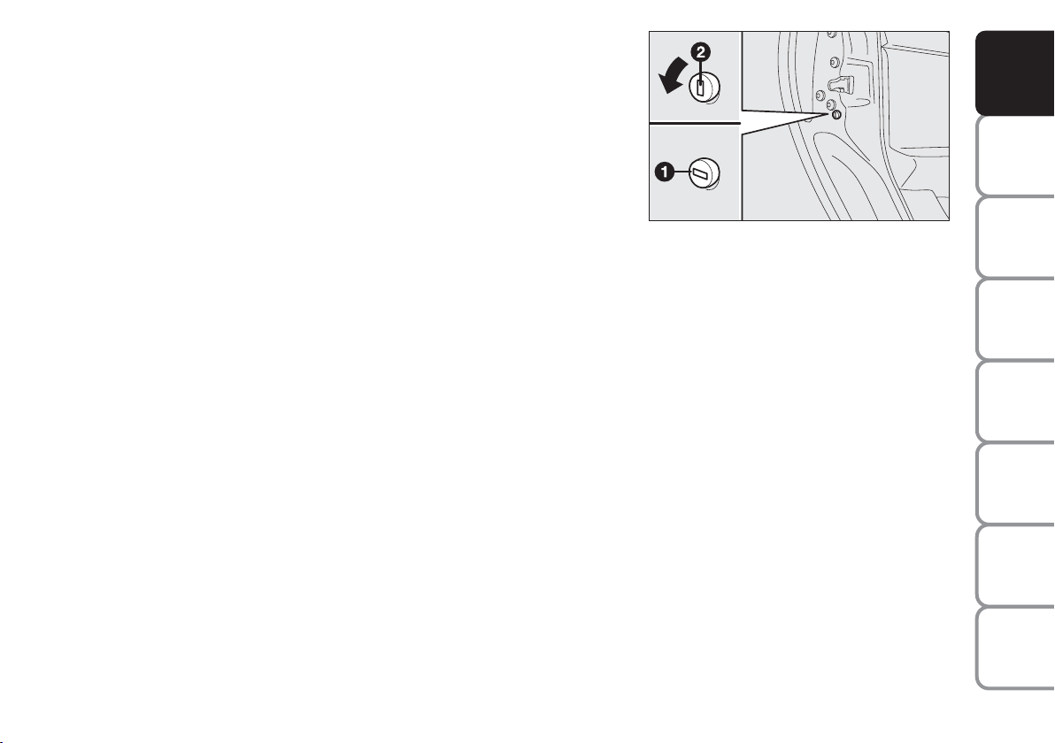
CHILD LOCK (5-door versions)
To prevent opening the rear doors from the inside.
This device can be engaged only with doors open:
❒ position 1 - engaged (door locked);
❒ position 2 - disengaged (door openable from inside).
The device is engaged even if the doors are unlocked by the centralised
system.
IMPORTANT Always use the lock when transporting children.
IMPORTANT After engaging the lock, check by trying to open a rear
door with the internal handle.
F0I0129m
AND
CONTROLS
DASHBOARD
SAFETY
DEVICES
OF THE CAR
CORRECT USE
WARNING
MESSAGES
LIGHTS AND
IN AN
EMERGENCY
CAR
MAINTENANCE
TECHNICAL
INDEX
89
SPECIFICATIONS
Page 91

AND
CONTROLS
DASHBOARD
SAFETY
DEVICES
OF THE CAR
CORRECT USE
WARNING
MESSAGES
LIGHTS AND
IN AN
EMERGENCY
CAR
MAINTENANCE
F0I0154m
POWER WINDOWS (where provided)
CONTROLS
Power windows are controlled by two switches located on the
dashboard when the key is at MAR:
(A): to open/close the front left-hand window;
(B): to open/close the front right-hand window;
On certain versions the following is also possible:
❒ to open/close front windows within about 2 minutes with key at STOP
or removed (with side doors closed);
❒ to press button (A) for longer than half a second to activate the
automatic operation of the driver’s window: the window will stop
when it reaches the end of its travel or until the button is pressed
again.
TECHNICAL
SPECIFICATIONS
INDEX
90
WARNING
Improper use of the electric windows can be dangerous. Before and during their
operation ensure that any passengers are not at risk from the moving glass either
by personal objects getting caught in the mechanism or by being injured by it
directly. Always remove the ignition key when you get out of the car to prevent the
electric windows being operated accidentally and constituting a danger to the
people left in the car.
Page 92

BOOT
TAILGATE OPENING
To open the tailgate from outside, turn the ignition key in the lock.
To open the tailgate from the inside, pull lever (A) next to driver’s seat.
IMPORTANT Do not operate the lever (A) when the car is travelling.
Tailgate opening is facilitated by side gas shock springs.
On certain versions, opening the boot, the interior boot ceiling light will
come on.
F0I0198m
F0I0090m
AND
CONTROLS
DASHBOARD
SAFETY
DEVICES
OF THE CAR
CORRECT USE
WARNING
MESSAGES
LIGHTS AND
IN AN
EMERGENCY
CAR
MAINTENANCE
TECHNICAL
INDEX
91
SPECIFICATIONS
Page 93
AND
CONTROLS
DASHBOARD
SAFETY
DEVICES
OF THE CAR
CORRECT USE
WARNING
MESSAGES
LIGHTS AND
IN AN
EMERGENCY
TAILGATE CLOSING
To close, lower the tailgate until the lock clicks.
The addition of objects (speakers, spoilers, etc.) on the rear shelf or boot lid, except those
envisaged by the manufacturer, may prevent the gas filled struts at the sides of the boot from
working properly.
If the boot is not shut properly the warning light
´
comes on together with the message on
reconfigurable multifunction display (where provided)
(see “Warning lights and messages” chapter).
CAR
MAINTENANCE
TECHNICAL
SPECIFICATIONS
INDEX
92
WARNING
WARNING
When using the boot, make sure the loads you are carrying do not exceed the
permitted weight (see section “Technical specifications”). Also make sure the items
in the boot are arranged properly to prevent them being thrown forwards and
injuring passengers should you brake sharply.
Never travel with objects on the rear shelf to prevent them being thrown forwards
and injuring passengers in case of accident or sharp braking.
Page 94
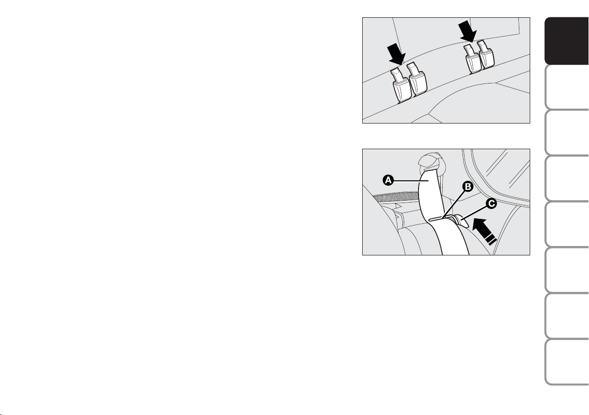
EXTENDING THE BOOT
Single rear seat
Proceed as follows:
❒ fasten the seat buckles to the tabs on the seat back (as shown by
arrows);
❒ check that the webbing (A) of each of the two side seat belts is
inserted into the respective belt guiding catch (B);
❒ release the seat back moving the levers (C) as shown by the arrow.
Tilt it to make a single loading surface with the boot floor.
Split rear seat back (where provided)
The boot can be extended completely or partially.
For partial extension fold the required seat side; proceed as follows:
❒ remove the parcel shelf (see next paragraph);
❒ press the button by the side of the two supports and remove the head
restraints by pulling them upwards;
❒ check that the webbing (A) of each of the two side seat belts is
inserted into the respective belt guiding tongue (B);
❒ release the seat back moving lever (C), then tilt it.
F0I0268m
F0I0137m
AND
CONTROLS
DASHBOARD
SAFETY
DEVICES
OF THE CAR
CORRECT USE
WARNING
MESSAGES
LIGHTS AND
IN AN
EMERGENCY
CAR
MAINTENANCE
TECHNICAL
SPECIFICATIONS
93
INDEX
Page 95
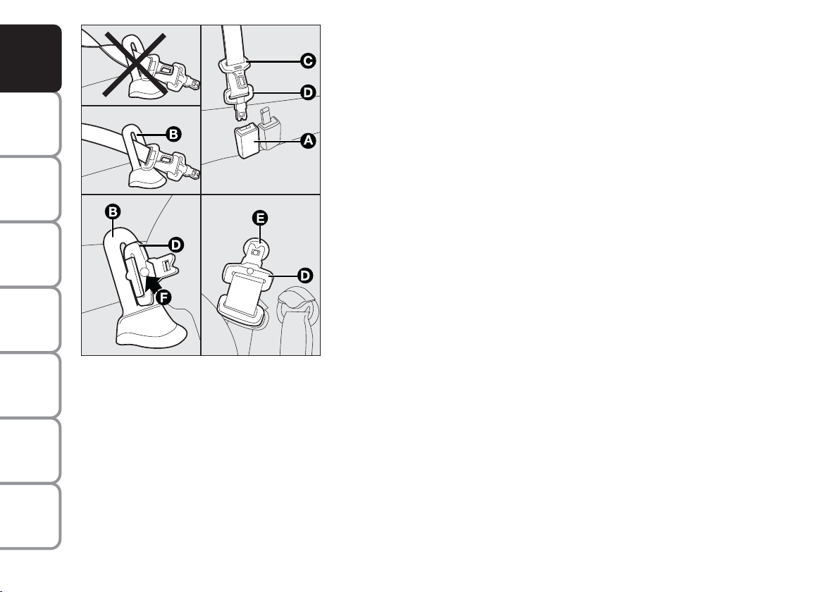
AND
CONTROLS
DASHBOARD
SAFETY
DEVICES
OF THE CAR
CORRECT USE
WARNING
MESSAGES
LIGHTS AND
IN AN
EMERGENCY
CAR
MAINTENANCE
F0I0192m
To fold the whole seat, lift the cushion and then tip the seat backs as
described for the rear single seat.
The central three-point seat belt and reel mechanism (where fitted) can
be removed as follows:
❒ press the black button on the buckle (A) if the seat belt is fastened;
❒ take the central belt slowly to the loop retainer (B) on the upper part
of the seat back and remove the second tongue (C) from the loop
retainer;
❒ remove the first tongue (D) from the loop retainer and fasten it to the
specific pin (E) on the rear pillar panel;
To restore conditions for use:
❒ release the first tongue (D) from pin (E);
❒ insert the first tongue (D) in loop retainer (B) without twisting the
belt. Make notch (F) on the belt tongue coincide with the respective
groove on the loop retainer and insert the second tongue (C) in the
loop retainer;
❒ pull the belt gently through loop retainer (B), and fasten the first
tongue (D) in buckle (A) (grey with black button). Make the two
yellow dots (one on the tongue and one on the buckle) coincide.
TECHNICAL
SPECIFICATIONS
INDEX
94
Page 96
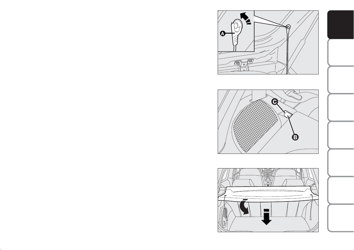
REAR WINDOW SHELF REMOVAL
Proceed as follows:
❒ release the upper ends (A) of the two tie-rods by removing the
eyelets;
❒ release the shelf eyelets (B) from their recesses (C);
❒ move the shelf towards the inside and turn it as shown in the figure to
remove.
Once removed, the shelf can be placed sideways between the backs of
the front seats and the cushion of the rear seat that has been tipped
down.
IMPORTANT If there is a fairly heavy load in the boot and you are
travelling at night, it is a good idea to check and adjust the height of the
dipped beam headlights (see “Headlights” in this section).
F0I0091m
F0I0092m
AND
CONTROLS
DASHBOARD
SAFETY
DEVICES
OF THE CAR
CORRECT USE
WARNING
MESSAGES
LIGHTS AND
IN AN
EMERGENCY
CAR
MAINTENANCE
F0I0093m
TECHNICAL
INDEX
95
SPECIFICATIONS
Page 97

RESTORING THE USE OF THE REAR SEAT
AND
CONTROLS
DASHBOARD
SAFETY
DEVICES
OF THE CAR
CORRECT USE
WARNING
MESSAGES
LIGHTS AND
IN AN
EMERGENCY
CAR
MAINTENANCE
TECHNICAL
SPECIFICATIONS
F0I0091m
Versions with single seat
Perform operations in a reverse order with respect to what previously
described for the boot extension operation. To prevent buckles from
remaining positioned below the cushion, check whether the buckles are
always coupled to the respective tongues located on the seat back.
Versions with split seat
Perform operations in a reverse order with respect to what previously
described for the boot extension operation. To prevent buckles from
remaining positioned below the cushion, couple buckles to the respective
side belt branches.
For versions with lap belt, couple the belt to its buckle and keep it raised
as the cushion is set back to its normal use position.
For versions with central three-point belt with reel, set the belt back to
use conditions (see previous pages), paying attention that the buckles are
ready for use.
INDEX
96
When refitting the parcel shelf, fasten the two side tie-rods (A) passing them on the inside of the
struts.
Page 98

BONNET
D
C
TO OPEN THE BONNET
Proceed as follows:
❒ pull lever (A) in the direction of the arrow;
❒ press lever (B) as shown by the arrow;
❒ open the bonnet and release the rod (C) from its clip at the same
time. Insert the end of the rod in its recess (D) on the bonnet.
IMPORTANT Before opening the bonnet, check the windscreen wiper
arms are not lifted from the windscreen.
F0I0095m
F0I0236m
AND
CONTROLS
DASHBOARD
SAFETY
DEVICES
OF THE CAR
CORRECT USE
WARNING
MESSAGES
LIGHTS AND
IN AN
EMERGENCY
CAR
MAINTENANCE
F0I0056m
TECHNICAL
SPECIFICATIONS
INDEX
97
Page 99
AND
CONTROLS
DASHBOARD
SAFETY
DEVICES
OF THE CAR
CORRECT USE
WARNING
MESSAGES
LIGHTS AND
TO CLOSE THE BONNET
Proceed as follows:
❒ hold the bonnet up with one hand and, with the
other, remove rod (C) from recess (D) replace it in
its clip;
❒ lower the bonnet at approx. 20 cm from the engine
compartment and then let it drop, ensuring that it is
fully closed and not just held in position by the
safety catch. If the bonnet does not close properly
do not push it down but open it again and repeat
the above procedure.
IMPORTANT Always check that the bonnet is closed
properly to avoid its opening while the car is travelling.
IN AN
EMERGENCY
CAR
MAINTENANCE
TECHNICAL
SPECIFICATIONS
INDEX
98
WARNING
WARNING
WARNING
For safety reasons the bonnet shall always be perfectly closed when travelling.
Always check for proper bonnet locking. If the bonnet is left inadvertently open,
stop the car immediately and close the bonnet.
The bonnet might fall violently if the support rod is not positioned properly.
Perform the above operations when the car is stationary.
Page 100

ROOF RACK/SKI RACK
FASTENERS
3-door versions
Move the seal aside in the points shown in the figure to reach the
fasteners.
The rear fasteners are in the areas indicated by the printed
mark Oon the rear side windows.
To make use of the presetting couplings, remove the retainer (A) by
operating on the relevant catch as shown in the figure.
O
reference
F0I0070m
AND
CONTROLS
DASHBOARD
SAFETY
DEVICES
OF THE CAR
CORRECT USE
WARNING
MESSAGES
LIGHTS AND
IN AN
EMERGENCY
CAR
MAINTENANCE
TECHNICAL
INDEX
99
SPECIFICATIONS
 Loading...