

Page 1
Montageanleitung 6 Руководство по эксплуатации 16
Assembly instructions 7 Návod k montáži 17
Notice d’emploi 8 Instrukcja montażu 18
Instrucciones de montaje 9 Összeszerelési utasítás 19
Istruzioni di montaggio 10 Οδηγίες συναρμολόγησης 20
Montagevoorschrift 11 Ръководство по монтаж 21
Monteringsanvisning 12 Paigaldusjuhend 22
Asennusohje 12 Naputak za montažu 23
Montagevejledning 13 Montâþas instrukcija 24
Monteringsveiledning 14 Naudojimo instrukcija 25
Instruções de montagem 15 Navodila za montažo 26
473330_004
ST
Page 2

Page 3
ST
1.1
1.2
1.3
1
1.4 1.5 1.6
2.1
2.2
2.3
2
Page 4
3a
3a.23a.1
3a.3 3a.4 3a.5
MFT/3-VL
3b.1
3b.2
3b.3
3b
Page 5
4.1
4.2
4.3
1 mm
4
5.1
5.1
5
5.2
5.2
Page 6

Schiebetisch ST
Der Schiebetisch besteht aus einer Führungsschiene (4.2), die an die linke Seite der
CS 50 EB/CMS GE/ MFT/3-VL montiert wird und
einem Schiebeschlitten (4.1), der auf der Führungsschiene läuft.
Zum Transport kann der Schiebeschlitten mit
dem Drehknopf (3a.5) auf der Führungsschiene
festgeklemmt werden.
Der Anschlag WRA 500 kann, analog zur CS 50
EB/CMS GE, an der umlaufenden Nut des Schiebeschlittens befestigt werden.
Montage CS 50/ CMS-GE
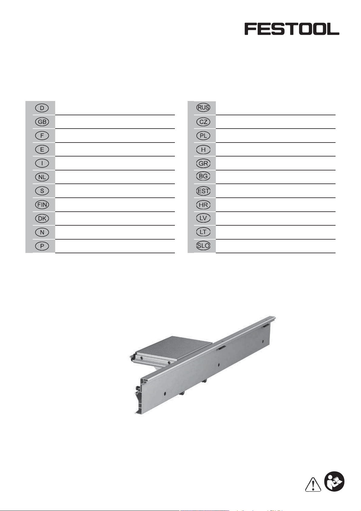
– Setzen Sie an den beiden äußeren Aussparungen
(1.1) des Grundgestells jeweils eine Halterung
mit den Zapfen (1.2) ein.
Achtung: die Überstände (1.3) auf den Halte-
rungen müssen jeweils nach außen zeigen.
– Verschieben Sie die Halterungen in der Nut (1.6)
so weit, bis deren äußere Kanten (mit den Überständen) mit den Fugen (1.4) des Grundgestells
übereinstimmen, und die Schnappverbindungen
an den Überständen in die Nut einrasten.
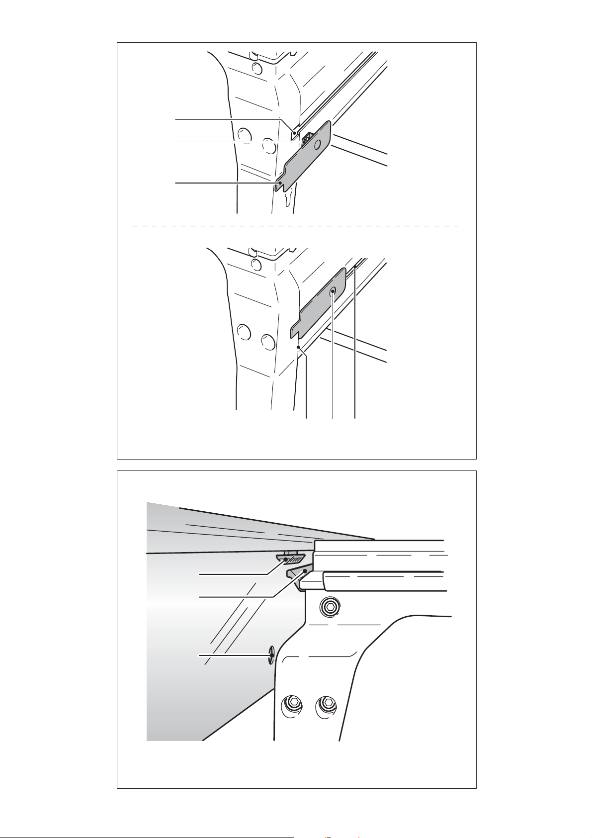
– Setzen Sie die Führungsschiene schräg von oben
mit den beiden Kunststoffhalterungen (2.1) in
die Nut (2.2) des Sägetisches ein.
– Schwenken Sie die Führungsschiene nach un-
ten, so dass die Zapfen (1.5) der Halterungen
in die Bohrungen (2.3) der Führungsschiene
eingreifen.
Anmerkung: Die Führungsschiene besitzt drei
Bohrungen, und kann daher in zwei Stellungen
(Überstand nach hinten oder vorne) befestigt
werden.
– Schrauben Sie die Führungsschiene mit den
beiden Drehknöpfen (3a.3) fest.
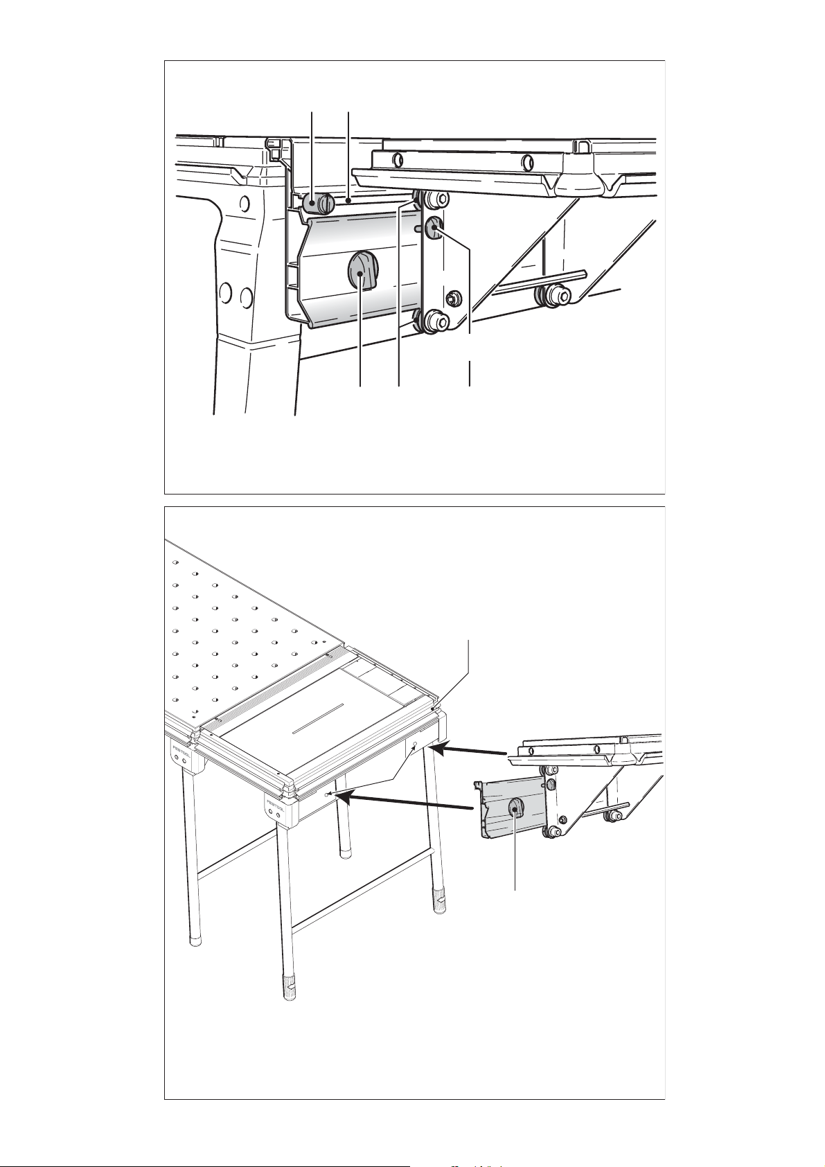
– Schieben Sie den Schiebeschlitten entspre-
chend Abb. 3 mit den vier Rollen (3a.4) von der
Seite her auf die Führungsschiene.
– Schrauben Sie die Endanschläge (3a.1) an den
beiden Enden der Nut (3a.2) fest.
Montage MFT/3-VL
– Setzen Sie die Führungsschiene schräg von oben
mit den beiden Kunststoffhalterungen (2.1) in
die Nut (3b.1) der Verlängerung ein.
– Schwenken Sie die Führungsschiene nach unten,
so dass die Drehknöpfe der Führungsschiene
(3b.3) in die Bohrungen (3b.2) der Verlängerung
eingreifen.
Anmerkung: Die Führungsschiene besitzt drei
Bohrungen, und kann daher in zwei Stellungen
(Überstand nach hinten oder vorne) befestigt
werden.
– Schrauben Sie die Führungsschiene mit den
beiden Drehknöpfen (3b.3) fest.
– Schieben Sie den Schiebeschlitten entsprechend
Abb. 3a mit den vier Rollen (3a.4) von der Seite
her auf die Führungsschiene.
– Schrauben Sie die Endanschläge (3a.1) an den
beiden Enden der Nut (3a.2) fest.
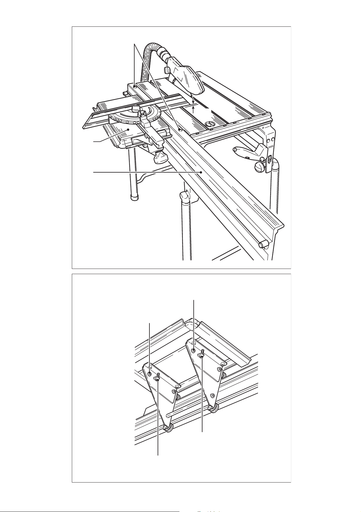
Höhenverstellung
– Öffnen Sie die beiden Drehknöpfe (3a.3).
– Verdrehen Sie die beiden Innensechskantschrau-
ben (4.3) so weit, bis das Anschlaglineal ca. 1
mm am Sägetisch übersteht.
– Schließen Sie die Drehknöpfe (3a.3).
Winkelverstellung
– Öffnen Sie die beiden Schrauben (5.1).
– Verdrehen Sie die Schraube (5.2), bis die Auf-
lagefl äche des Schiebeschlittens parallel zur
Tischfl äche der Tischkreissäge ist. Kontrollieren
Sie die Parallelität, indem Sie ein gerades Lineal
über den Schiebeschlitten und den Tisch der
Tischkreissäge legen.
– Schließen Sie die beiden Schrauben (5.1).
6
Page 7

Sliding table ST
The sliding table consists of a guide rail
(4.2) which is mounted to the left side of the
CS 50 EB/CMS GE/ MFT/3-VL and a carriage (4.1)
which slides on the guide rail.
For transport, the slide can be fi xed to the guide
rail using the rotary knob (3a.5).
Stop WRA 500 can be attached to the curved
groove on the carriage at the same time as the
CS 50 EB/CMS GE.
Fitting CS 50/ CMS-GE
– Attach one bracket at each of the two external
recesses (1.1) on the base chassis using the peg
(1.2).
Caution: the protruding points (1.3) on each of
the brackets must point outwards.
– Slide the brackets into the groove (1.6) until the
outer edge (with protruding points) lines up with
the join (1.4) on the base frame and the snapon clips lock onto the protruding points in the
groove.
– Lower the guide rails into position at an angle,
locating both plastic brackets (2.1) in the groove
(2.2) on the saw table.
– Swivel the guide rails downwards so that the
pegs (1.5) on the brackets engage in the holes
(2.3) on the guide rails.
Note: the guide rail has three drilled holes and
can therefore be secured in two positions (protruding point to the rear or front).
– Secure the guide rails using the two rotary knobs
(3a.3).
– Slide the carriage with the four rollers (3a.4)
onto the guide rails from the side as shown in
Fig. 3a.
– Secure the end stops (3a.1) at both ends of the
groove (3a.2).
Fitting MFT/3-VL
– Insert the guide rail into the groove (3b.1) on the
extension at an angle from above with the two
plastic brackets (2.1).
– Lower the guide rail so that the rotary knobs on
the guide rail (3b.3) engage in the holes (3b.2)
on the extension.
Note: the guide rail has three drilled holes and
can therefore be secured in two positions (protruding point to the rear or front).
– Secure the guide rails using the two rotary knobs
(3b.3).
– Slide the carriage with the four rollers (3a.4)
onto the guide rails from the side as shown in
Fig. 3a.
– Secure the end stops (3a.1) at both ends of the
groove (3a.2).
Height adjustment
– Unscrew both rotary knobs (3a.3).
– Turn both Allen screws (4.3) until the sliding
fence is approx. 1 mm above the saw table.
– Tighten the rotary knobs (3a.3).
Angle adjustment
– Angle adjustment
– Open both screws (5.1).
– Turn the screw (5.2) until the contact surface of
the slide is parallel to the table surface of the
bench circular saw. Check the parallelism by
placing a straight ruler over the slide and the
table of the bench circular saw.
– Close both screws (5.1).
7
Page 8

Table coulissante ST
La table coulissante est constituée d’un rail de
guidage (4.2) monté du côté gauche du CS 50 EB/
CMS GE/ MFT/3-VL et d’un chariot coulissant (4.1)
se déplaçant sur le rail de guidage.
Pour le transport, le chariot coulissant et le sélecteur de fonction (3a.5) peuvent être fi xés sur
le rail de guidage.
La butée WRA 500, comme sur le CS 50 EB/CMS
GE, peut être fi xée à la rainure faisant le tour du
chariot coulissant.
Montage CS 50/ CMS-GE
– Dans les deux évidements extérieurs (1.1) du
bâti de base, posez à chaque fois un logement
avec les tenons (1.2).
Attention : les fl èches (1.3) des logements doi-
vent être orientées vers l’extérieur.
– Poussez les logements dans la rainure (1.6)
jusqu’à ce que les bords extérieurs (avec les
fl èches) soient positionnés sur la jointure (1.4)
, du bâti de base et que les assemblages à encliquetage s’enclenchent dans la jointure aux
niveaux des fl èches.
– Pour monter le rail de guidage, inclinez-le et
positionnez les deux pièces en plastique (2.1)
par le haut dans la rainure (2.2) de la table de
sciage.
– Inclinez le rail de guidage vers le bas de manière
à ce que les tenons (1.5) des renforts s’insèrent
dans les orifi ces (2.3) du rail de guidage.
Remarque : Le rail de guidage possède trois fo-
rages et peut donc être fi xé dans deux positions
(fl èche vers l’arrière ou vers l’avant).
– Serrez le rail de guidage avec les deux écrous
moletés (3a.3).
– Insérez le chariot coulissant sur le rail de gui-
dage par le côté à l’aide des quatre galets (3a.4)
comme indiqué sur l’ill. 3a.
– Vissez les butées (3a.1) aux deux extrémités de
la rainure (3a.2).
Montage MFT/3-VL
– Insérez le rail de guidage en biais par le haut
avec les deux supports en plastique (2.1) dans
la rainure (3b.1) de la rallonge.
– Pivotez le rail de guidage vers le bas, de manière
à ce que les boutons rotatifs du rail de guidage
(3b.3) s’engagent dans les orifi ces (3b.2) de la
rallonge.
Remarque : Le rail de guidage possède trois fo-
rages et peut donc être fi xé dans deux positions
(fl èche vers l’arrière ou vers l’avant).
– Serrez le rail de guidage avec les deux écrous
moletés (3b.3).
– Insérez le chariot coulissant sur le rail de gui-
dage par le côté à l’aide des quatre galets (3a.4)
comme indiqué sur l’ill. 3a.
– Vissez les butées (3a.1) aux deux extrémités de
la rainure (3a.2).
Réglage en hauteur
– Desserrez les deux molettes (3a.3).
– Vissez ou dévissez les deux vis à tête imbus
(4.3) jusqu’à ce que la règle de butée dépasse
d’env. 1 mm par rapport au niveau de la table
de sciage.
– Serrez les deux molettes (3a.3).
Réglage angulaire
– Desserrez les deux vis (5.1).
– Vissez ou dévissez la vis (5.2), jusqu‘à ce que
la surface d‘appui du chariot coulissant soit
parallèle à la surface de la table de la scie stationnaire. Vérifi ez le parallélisme en posant une
règle à cheval sur le chariot coulissant et la table
de la scie stationnaire.
– Serrez les deux vis (5.1).
8
Page 9

Mesa corredera ST
La mesa corredera se compone de un riel de guía
(4.2) que se monta en el lateral izquierdo de la CS
50 EB/CMS GE/ MFT/3-VL y un carro móvil (4.1)
que se desplaza por el riel de guía.
Para el transporte, el carro deslizante puede
apretarse con el botón giratorio (3a.5) del riel de
guía.
El tope WRA 500 puede fi jarse, al igual que en CS
50 EB/CMS GE, en la ranura circular del carro
móvil.
Montaje CS 50/ CMS-GE
– Fijar un elemento de soporte con perno (1.2) en
cada una de las dos entalladuras exteriores (1.1)
del bastidor.
Atención: las partes salientes (1.3) en los ele-
mentos de soporte deben señalar al exterior.
– Deslizar los elementos de soporte en la ranura
(1.6) hasta que los bordes exteriores (con las
partes salientes) coincidan con las entalladuras
(1.4) del bastidor base , y las conexiones rápidas
de las partes salientes encajen en la ranura.
– Colocar el riel guía de forma inclinada desde
arriba introduciendo las dos barras de apoyo
de plástico (2.1) en la ranura (2.2) de la mesa
de serrar.
– Abatir el riel de guía hacia abajo hasta que los
pernos (1.5) de los elementos de soporte queden enclavados en los taladros (2.3) del riel de
guía.
Nota: el riel de guía tiene tres taladros y por
tanto puede fi jarse en dos posiciones (parte
saliente hacia atrás o hacia delante).
– Fijar el riel de guía mediante los dos reguladores
(3a.3).
– Deslizar lateralmente el carro móvil con las
cuatro ruedas (3a.4) a lo lago del riel como se
indica en la fi gura 3a.
– Atornillar los topes fi nales (3a.1) en los extremos
de la ranura (3a.2).
Montaje MFT/3-VL
– Introduzca el riel de guía de forma inclinada
desde arriba con los dos soportes de plástico
(2.1) en la ranura (3b.1) de la prolongación.
– Gire el riel de guía hacia abajo de modo que los
botones giratorios del riel de guía (3b.3) encajen
en los orifi cios (3b.2) de la prolongación.
Nota: el riel de guía tiene tres taladros y por tanto
puede fi jarse en dos posiciones (parte saliente
hacia atrás o hacia delante).
– Fijar el riel de guía mediante los dos reguladores
(3b.3).
– Deslizar lateralmente el carro móvil con las
cuatro ruedas (3a.4) a lo lago del riel como se
indica en la fi gura 3a.
– Atornillar los topes fi nales (3a.1) en los extremos
de la ranura (3a.2).
Ajuste de la altura
– Desenroscar los dos reguladores (3a.3).
– Ajustar ambos tornillos de cabeza con hexágono
interior (4.3) de manera que la regla de tope
sobresalga aprox. 1 mm por encima de la mesa
de serrar.
– Enroscar los reguladores (3a.3).
Ajuste del ángulo
– Afl oje los dos tornillos (5.1).
– Gire el tornillo (5.2) hasta que la superfi cie de
apoyo del carro deslizante se encuentre paralela
a la superfi cie de la mesa de la sierra circular
estacionaria. Compruebe el paralelismo colocando una regla recta sobre el carro deslizante
y la mesa de la sierra circular estacionaria.
– Apriete los dos tornillos (5.1).
9
Page 10

Carrello scorrevole ST
Il carrello scorrevole è composto da un binario
di guida (4.2) montato sul lato sinistro del CS 50
EB/CMS GE/ MFT/3-VL e una slitta di scorrimento
(4.1) che scorre anche sul binario di guida.
Per il trasporto è possibile fi ssare il cursore con
la manopola (3a.5) sul binario di guida.
Il riscontro WRA 500 può essere fi ssato, analogamente al CS 50 EB/CMS GE, nella scanalatura
della slitta di scorrimento.
Montaggio CS 50/ CMS-GE
– Inserire con i perni (1.2) un supporto in entrambe
le scanalature esterne (1.1) del telaio di base.
Attenzione: le sporgenze (1.3) sui supporti de-
vono sempre essere rivolte verso l’esterno.
– Spostare i supporti nella scanalatura (1.6) fi no a
far combaciare i bordi esterni (con le sporgenze) con i giunti (1.4) del telaio di base, quindi
inserire i giunti a molla sulle sporgenze nella
scanalatura.
– Inserire il binario di guida obliquamente dall’alto
con i due supporti in plastica (2.1) nella scanalatura (2.2) della sega da banco.
– Orientare il binario di guida verso il basso, co-
sicché i perni (1.5) dei supporti si inseriscano
nei fori (2.3) del binario di guida.
Nota: il binario di guida è dotato di tre fori,
pertanto può essere fi ssato in due posizioni
(sporgenza verso il retro o frontale).
– Avvitare il binario di guida con entrambe le ma-
nopole (3a.3).
– Spostare le slitte di scorrimento con le quattro
rotelle (3a.4) dal lato sul binario di guida, come
illustrato in fi gura 3a.
– Fissare le battute d’arresto (3a.1) su entrambe
le estremità della scanalatura (3a.2).
Montaggio MFT-3/VL
– Inserire il binario di guida inclinato dall’alto
con entrambi i supporti di plastica (2.1) nella
scanalatura (3b.1) della prolunga.
– Ruotare in basso il binario di guida in modo che
le manopole del binario di guida (3b.3) si innestino nei fori (3b.2) della prolunga.
Nota: il binario di guida è dotato di tre fori,
pertanto può essere fi ssato in due posizioni
(sporgenza verso il retro o frontale).
– Avvitare il binario di guida con entrambe le ma-
nopole (3b.3).
– Spostare le slitte di scorrimento con le quattro
rotelle (3a.4) dal lato sul binario di guida, come
illustrato in fi gura 3a.
– Fissare le battute d’arresto (3a.1) su entrambe
le estremità della scanalatura (3a.2).
Regolazione in altezza
– Allentare le due manopole (3a.3).
– Ruotare entrambe le viti a esagono interno (4.3)
fi nché la riga di riscontro raggiunge una distanza
di ca. 1 mm sopra alla sega da banco.
– Stringere le manopole (3a.3).
Regolazione dell‘angolo
– Aprire le due viti (5.1).
– Girare la vite (5.2) fi nché la superfi cie di appog-
gio della slitta di scorrimento è parallela alla
superfi cie del banco sega. Controllare il parallelismo appoggiando una riga diritta sulla slitta di
scorrimento e sul banco della sega circolare.
– Chiudere le due viti (5.1).
10
Page 11

Schuiftafel ST
De schuiftafel bestaat uit een geleiderail (4.2),
die aan de linkerkant van de CS 50 EB/ CMS
GE/ MFT/3-VL wordt gemonteerd, en een
schuifslede (4.1), die op de geleiderail loopt.
Voor het transport kan de schuifslede met de
draaiknop (3a.5) op de geleiderail worden vastgeklemd.
De aanslag WRA 500 kan, analoog aan de CS
50 EB/CMS GE, in de omlopende groef van de
schuifslede worden bevestigd.
Montage CS 50/ CMS-GE
– Plaats in de beide buitenste uitsparingen (1.1)
van het basisframe een houder met pennen
(1.2).
Let op: de pijlen (1.3) op de houders moeten naar
buiten wijzen.
– Schuif aan de houders in de groef (1.6) totdat de
buitenste randen (met de pijlen) overeenstemmen met de voegen (1.4) van het basisframe
en de klikverbindingen op de randen in de voeg
klikken.
– Plaats de geleiderail schuin van boven met de
beide kunststofhouders (2.1) in de groef (2.2)
van de zaagtafel.
– Draai de geleiderail naar onderen, zodat de pen-
nen (1.5) van de houders in de boringen (2.3) van
de geleiderail grijpen.
Opmerking: de geleiderail beschikt over drie
boorgaten en kan daarom in twee standen
(rand naar achteren of naar voren) bevestigd
worden.
– Schroef de geleiderail vast met de beide draai-
knoppen (3a.3).
– Schuif de geleideslede volgens afb. 3a met de
vier rollen (3a.4) vanaf de zijkant op de geleiderail.
– Schroef de eindaanslagen (3a.1) vast aan de
beide uiteinden van de groef (3a.2).
Montage MFT/3-VL
– Breng de geleiderail schuin van bovenaf met de
beide kunststof houders (2.1) in de groef (3b.1)
van de verlenging in.
– Draai de geleiderail naar beneden, zodat de
draaiknoppen van de geleiderail (3b.3) in de
boorgaten (3b.2) van de verlenging grijpen.
Opmerking: de geleiderail beschikt over drie
boorgaten en kan daarom in twee standen
(rand naar achteren of naar voren) bevestigd
worden.
– Schroef de geleiderail vast met de beide draai-
knoppen (3b.3).
– Schuif de geleideslede volgens afb. 3a met de
vier rollen (3a.4) vanaf de zijkant op de geleiderail.
– Schroef de eindaanslagen (3a.1) vast aan de
beide uiteinden van de groef (3a.2).
Hoogteverstelling
– Open de beide draaiknoppen (3a.3).
– Draai aan de beide inbusschroeven (4.3) tot de
aanslaglineaal ca. 1 mm boven de zaagtafel
uitsteekt.
– Sluit de draaiknoppen (3a.3).
Hoekverstelling
– Draai de beide schroeven (5.1) los.
– Verdraai de schroef (5.2), tot het steunvlak van
de schuifslede parallel met het tafelvlak van de
tafelcirkelzaag is. Controleer de parallelliteit
door een rechte liniaal over de schuifslede en
de tafel van de tafelcirkelzaag te leggen.
– Draai de beide schroeven (5.1) aan.
11
Page 12

Justerbord ST
Justerbordet består av en rälsstyrskena (4.2),
som monteras på den vänstra sidan av CS 50 EB/
CMS GE/ MFT/3-VL, och en släde (4.1) som löper
i styrskenan.
Vid transport kan skjutsliden klämmas fast på
styrskenan med vridknappen (3a.5).
I likhet med CS 50 EB/CMS GE kan anslaget WRA
500 fästas i det kringgående spåret på släden.
Montering CS 50/ CMS-GE
– Sätt fast en hållare i de båda ursparningarna
(1.1) på grundenheten genom att sticka in tapparna (1.2).
OBS! Överhängen (1.3) på hållarna måste alltid
peka utåt.
– Skjut in hållarna i spåret (1.6) tills den yttre kan-
ten (med överhängen) ligger jäms med fogarna
(1.4) i grundenheten, och snäppförslutningarna
på överhängen faller på plats i spåret.
– Sätt in styrskenan snett ovanifrån med de båda
plasthållarna (2.1) i spåret (2.2) på sågbordet.
– Sväng ner styrskenan så att tapparna (1.5) på
hållarna hakar fast i hålen (2.3) på styrskenan.
Anmärkning: Det fi nns tre hål på styrskenan,
och den kan därför fästas i två lägen (överhäng
bakåt eller framåt).
– Skruva fast styrskenan med de båda vreden
(3a.3).
– Skjut på släden med de fyra rullarna (3a.4) från
sidan på styrskenan, se bild 3a.
– Skruva fast ändanslagen (3a.1) i båda ändarna
av spåret (3a.2).
Montering MFT/3-VL
– Sätt styrskenan snett uppifrån med de båda
plasthållarna (2.1) i spåret (3b.1) i förlängningen.
– Sväng ner styrskenan, så att dess vridknappar
(3b.3) greppar i hålen (3b.2) i förlängningen.
Anmärkning: Det fi nns tre hål på styrskenan,
och den kan därför fästas i två lägen (överhäng
bakåt eller framåt).
– Skruva fast styrskenan med de båda vreden
(3b.3).
– Skjut på släden med de fyra rullarna (3a.4) från
sidan på styrskenan, se bild 3a.
– Skruva fast ändanslagen (3a.1) i båda ändarna
av spåret (3a.2).
Höjdinställning
– Lossa de båda vreden (3a.3).
– Vrid de båda insexskruvarna (4.3) tills anslags-
linjalen står ca 1 mm över sågbordet.
– Vrid åt vreden (3a.3).
Vinkelinställning
– Lossa de båda skruvarna (5.1).
– Vrid skruven (5.2) tills skjutslidens anligg-
ningsyta är parallell mot bordsytan på bordcirkelsågen. Kontrollera parallelliteten genom att
lägga en rak linjal över skjutsliden och bordet
på bordcirkelsågen.
– Dra åt de båda skruvarna (5.1).
Työntöpöytä ST
Työntöpöytä koostuu ohjauskiskosta (4.2), joka
asennetaan CS 50 EB/CMS GE/ MFT/3-VL:n vasemmalle puolelle ja työntökelkasta (4.1), joka
liikkuu ohjauskiskolla.
Kuljetusta varten työntökelkka voidaan kiinnittää
kierrettävällä nupilla (3a.5) ohjainkiskoon.
Ohjain WRA 500 voidaan kuten CS 50 EB/ CMS GE
kiinnittää työntökelkan pyörivään uraan.
Asennus CS 50/ CMS-GE
– Laita perusrungon molempiin ulkoreikiin (1.1)
aina kiinnike tapilla (1.2).
Huomio: kiinnikkeissä olevan yläosan (1.3) täytyy
aina osoittaa ulospäin.
– Työnnä kiinnikkeet uraan (1.6) niin pitkälle
kunnes niiden ulkoreunat ( yläosilla) vastaavat
perusrungon saumaa (1.4) ja pikaliitokset yläosissa lukkiutuvat uraan.
– Laita ohjauskisko vinottain ylhäältä molempien
muovikiinnikkeiden (2.1) kanssa sahauspöydän
uraan (2.2).
– Käännä ohjauskisko alaspäin, niin että kiinnik-
12
Page 13

keiden tapit (1.5) osuvat ohjauskiskon reikiin
(2.3).
Huomautus: Ohjainkiskossa on kolme reikää
ja siksi ne voidaan kiinnittää kahteen asentoon
(yläreuna ylös-ßßßtai eteenpäin).
– Ruuvaa ohjauskisko molemmilla kierrettävillä
nupeilla (3a.3) kiinni.
– Työnnä työntökelkka kuvan 3a mukaisesti nel-
jällä rullalla (3a.4) sivulta ohjauskiskolle.
– Ruuvaa pääterajoitin (3a.1) uran (3a.2) molem-
piin päihin kiinni.
Asennus MFT/3-VL
– Laita viistosti ylhäältäpäin ohjainkiskon kum-
matkin muoviset pitimet (2.1) jatko-osan uraan
(3b.1).
– Käännä ohjainkiskoa alaspäin siten, että oh-
jainkiskon kiertonupit (3b.3) osuvat jatko-osan
reikiin (3b.2).
Huomautus: Ohjainkiskossa on kolme reikää
ja siksi ne voidaan kiinnittää kahteen asentoon
(yläreuna ylös-ßßßtai eteenpäin).
– Ruuvaa ohjauskisko molemmilla kierrettävillä
nupeilla (3b.3) kiinni.
– Työnnä työntökelkka kuvan 3a mukaisesti nel-
jällä rullalla (3a.4) sivulta ohjauskiskolle.
– Ruuvaa pääterajoitin (3a.1) uran (3a.2) molem-
piin päihin kiinni.
Korkeuden säätö
– Avaa molemmat kierrettävät nupit (3a.3).
– Kierrä molempia kuusiokoloruuveja (4.3) niin
pitkälle kunnes rajoitinviivain on n. 1 mm sahauspöydän yläpuolella.
– Sulje kierrettävät nupit (3a.3).
Kulman säätö
– Avaa molemmat ruuvit (5.1).
– Kierrä ruuvia (5.2), kunnes työntökelkan vas-
tinpinta on yhdensuuntainen pöytäpyörösahan
pöytäpintaan nähden. Tarkasta yhdensuuntaisuus asettamalla suora viivain työntökelkan ja
pöytäpyöräsahan pöydän päälle.
– Kierrä molemmat ruuvit (5.1) kiinni.
Rullebord ST
Rullebordet består af en føringsskinne (4.2), som
monteres på den højre side af CS 50 EB/CMS
GE/ MFT/3-VL, og en trækfunktion (4.1), som løber
på føringsskinnen.
Ved transport kan trækfunktionen fastspændes til
føringsskinnen med drejeknappen (3a.5).
Anslaget WRA 500 kan ligesom CS 50 EB/ CMS
GE fastgøres til trækfunktionens omkringliggende
not.
Montering CS 50/ CMS-GE
– Sæt en holder i hver af grundstativets to yderste
udsparinger (1.1) ved hjælp af tapperne (1.2).
Bemærk: Udhængene (1.3) på holderne skal
pege udad.
– Forskyd holderne i noten (1.6), indtil deres yder-
kanter (med udhængene) ligger på linje med
fugerne (1.4) på grundstativet, og snapforbindelserne på udhængene går i indgreb i noten.
– Sæt føringsskinnen i skråt fra oven, idet de to
plastholdere (2.1) placeres i arbejdsbordets not
(2.2).
– Sving føringsskinnen ned, så holdernes tapper
(1.5) går i indgreb i føringsskinnens boringer
(2.3).
Bemærk: Føringsskinnen har tre boringer og
kan derfor fastgøres i to stillinger (udhæng
bagtil eller fortil).
– Skru føringsskinnen fast med de to drejeknap-
per (3a.3).
– Skyd trækfunktionen på føringsskinnen fra siden
af med de fi re hjul (3a.4) i henhold til fi g. 3a.
– Skru endeanslagene (3a.1) i notens (3a.2) to
ender fast.
Montering MFT/3-VL
– Sæt føringsskinnen skråt ovenfra i noten (3b.1)
på forlængerbordet ved hjælp af de to plastholdere.
– Sving føringsskinnen ned, så føringsskinnens
drejeknapper (3b.3) griber ind i forlængerbordets huller (3b.2).
Bemærk: Føringsskinnen har tre boringer og
kan derfor fastgøres i to stillinger (udhæng
bagtil eller fortil).
– Skru føringsskinnen fast med de to drejeknap-
per (3b.3).
– Skyd trækfunktionen på føringsskinnen fra siden
af med de fi re hjul (3a.4) i henhold til fi g. 3a.
– Skru endeanslagene (3a.1) i notens (3a.2) to
ender fast.
13
Page 14

Højdejustering
– Løsn de to drejeknapper (3a.3).
– Drej de to unbrakoskruer (4.3), indtil anslagsli-
nealen er ca. 1 mm over arbejdsbordet.
– Spænd drejeknapperne (3a.3).
Skyvebord ST
Vinkeljustering
– Løsn de to skruer (5.1).
– Drej skruen (5.2), indtil trækfunktionens ar-
bejdsfl ade er parallel med rundsavens bordplade. Kontroller paralleliteten ved at lægge en lige
lineal hen over trækfunktionen og rundsavens
bord.
– Spænd de to skruer (5.1).
Skyvebordet består av en føringsskinne (4.2) der
CS 50 EB/CMS GE/ MFT/3-VL er montert på venstre side samt en skyveslede (4.1) som beveger
seg på føringsskinnen.
Ved transport kan skyvesleiden med dreieknappen (3a.5) klemmes fast på styreskinnen.
Anlegget WRA 500 kan, på tilsvarende måte som
CS 50 EB/CMS GE festes på det omløpende sporet
på skyvesleden.
Montasje CS 50/ CMS-GE
– Sett inn en holder med tapper (1.2) på hver av
de to ytre utsparingene (1.1) på understellet.
NB! De utstikkende endene (1.3) på holderne
skal peke utover.
– ßForskyv holderne i sporet (1.6) inntil de ytre
kantene (med de utsikkende endene) er i fl ukt
med fugene (1.4) på understellet og hurtigkoblingen på de utstikkende endene klikker på plass
i sporet.
– Sett føringsskinnen på skrå ovenfra inn i sag-
bordet slik at de to holderne av plast (2.1) går
inn i sporet (2.2) på sagbordet.
– Vipp ned føringsskinnen, slik at tappene (1.5) til
holderne griper inn hullene (2.3) på føringsskinnen.
Merk: Styreskinnen har tre hull og kan dermed
festes i to stillinger (overheng bakover eller
forover).
– Skru fast føringsskinnen med de to vriderne
(3a.3).
– Skyv skyvesleden inn på føringsskinnen fra siden
med de fi re rullene (3a.4) slik det fremgår av
bilde 3a.
– Skru fast endestopperne (3a.1) i begge ender av
sporet (3a.2).
Montasje MFT/3-VL
- Sett styreskinnen på skrå ovenfra inn i forlengelsen slik at de to holderne av plast (2,1) går
inn i sporet (3b,1) på forlengelsen.
- Sving styreskinnen nedover, slik at vriderne på
styreskinnen (3b,3) griper i hullene (3b,2) på
forlengelsen.
Merk: Styreskinnen har tre hull og kan dermed
festes i to stillinger (overheng bakover eller
forover).
– Skru fast føringsskinnen med de to vriderne
(3b.3).
– Skyv skyvesleden inn på føringsskinnen fra siden
med de fi re rullene (3a.4) slik det fremgår av
bilde 3a.
– Skru fast endestopperne (3a.1) i begge ender av
sporet (3a.2).
Høyderegulering
– Åpne de to vriderne (3a.3).
– Vri de to unbrakoskruene (4.3) inntil anleggs-
skinnnen står ca. 1 mm over sagbordet.
– Lukk de to vriderne (3a.3).
Vinkelregulering
– Løsne begge skruene (5.1).
– Vri skruen (5.2) til bærefl aten på føringsskinnen
er parallell med bordfl aten på bordsirkelsagen.
Kontroller parallelliteten ved å legge en rett
linjal over føringsskinnen og bordet på bordsirkelsagen.
– Stram begge skruene (5.1).
14
Page 15

Mesa esquadrejadeira ST
A mesa esquadrejadeira é constituída por um
trilho-guia (4.2), que é montado no lado esquerdo do CS 50 EB/CMS GE/ MFT/3-VL, e um carro
corrediço (4.1), que se move no trilho-guia.
Para o transporte, o patim corrediço pode ser
fi xado por aperto no trilho-guia através do punho
giratório (3a.5).
De modo semelhante ao CS 50 EB/CMS GE, o batente WRA 500 pode ser fi xo à ranhura circundante
do carro corrediço.
Montar CS 50/ CMS-GE
– Em ambos os entalhes exteriores (1.1) da arma-
ção base, coloque respectivamente um suporte
com a cavilha (1.2).
Atenção: as protuberâncias (1.3) nos suportes
devem apontar para fora.
– Desloque os suportes na ranhura (1.6) até os
cantos exteriores (com as protuberâncias) coincidirem com as fendas (1.4) da armação base,
e as uniões de engate engatarem na ranhura
pelas protuberâncias.
– Introduza o trilho-guia obliquamente, pelo lado
de cima, com os dois suportes de plástico (2.1)
na ranhura (2.2) da bancada de serra.
– Vire o trilho-guia para baixo, de modo a que as
cavilhas (1.5) dos suportes encaixem nos orifícios (2.3) do trilho-guia.
Nota: o trilho-guia possui três orifícios, podendo
por isso ser fi xo em duas posições (protuberância para trás ou para a frente).
– Aparafuse o trilho-guia com ambos os botões
giratórios (3a.3).
– Com os quatros rolos (3a.4), desloque o carro
corrediço a partir da parte lateral, de acordo
com a fi g. 3a, para o trilho-guia.
– Aparafuse os batentes de fi m de curso (3a.1)
nas duas extremidades da ranhura (3a.2).
Montar MFT/3-VL
– Insira o trilho-guia na ranhura (3b.1) do prolon-
gamento, de forma inclinada e pelo lado de cima,
com ambos os suportes de plástico (2.1).
– Incline o trilho-guia para baixo, de modo a que
os botões giratórios do trilho-guia (3b.3) engatem nos furos (3b.2) do prolongamento.
Nota: o trilho-guia possui três orifícios, podendo
por isso ser fi xo em duas posições (protuberância para trás ou para a frente).
– Aparafuse o trilho-guia com ambos os botões
giratórios (3b.3).
– Com os quatros rolos (3a.4), desloque o carro
corrediço a partir da parte lateral, de acordo
com a fi g. 3a, para o trilho-guia.
– Aparafuse os batentes de fi m de curso (3a.1)
nas duas extremidades da ranhura (3a.2).
Ajuste em altura
– Abra ambos os botões giratórios (3a.3).
– Gire os dois parafusos de sextavado interior (4.3)
até a régua de batente sobressair aprox. 1 mm
acima da bancada de serra.
– Feche os botões giratórios (3a.3).
Ajuste do ângulo
– Desenrosque ambos os parafusos (5.1).
– Rode o parafuso (5.2) até a superfície de apoio
do carro corrediço fi car paralela à área da mesa
da serra circular de bancada. Verifi que o paralelismo, colocando uma régua direita sobre o
carro corrediço e a mesa da serra circular de
bancada.
– Enrosque ambos os parafusos (5.1).
15
Page 16

Раздвижной стол ST
Раздвижной стол состоит из направляющей
(4.2), монтируемой с левой стороны CS 50 EB/
CMS GE/ MFT/3-VL, и салазок (4.1), перемещающихся по направляющей.
При транспортировке подвижные салазки
можно закрепить на шине-направляющей при
помощи винта-барашка (3a.5).
Упор WRA 500 может, как и CS 50 EB/CMS GE,
крепиться при помощи поворотного паза салазок.
Монтаж CS 50/ CMS-GE
– Вставьте в обе внешних выемки (1.1) рамы
элемент крепления с цапфами (1.2).
Внимание: выступы (1.3) на элементах кре-
пления должны указывать наружу.
– Передвигайте элементы крепления в пазе
(1.6) до тех пор, пока внешние кромки (с выступами) не совпадут со швами (1.4) рамы,
и зажимы на выступах не зафиксируются в
пазу.
– Вставьте пластиковые крепления (2.1) на-
правляющей в паз (2.2) пильного стола.
– Опустите направляющую таким образом, что-
бы цапфы (1.5) элементов крепления вставились в отверстия (2.3) направляющей.
Примечание: На шине-направляющей рас-
положены три отверстия, и ее можно закрепить в двух положениях (выступом назад или
вперед).
– Зафиксируйте направляющую при помощи
обеих вращающихся ручек (3a.3).
– В соответствии с рис. 3a сдвиньте салазки к
направляющей при помощи четырех роликов
(3a.4).
– Накрепко привинтите концевые ограничители
перемещения (3a.1) по краям паза (3a.2).
Mонтаж MFT/3-VL
– Установите шину-направляющую под углом
сверху с помощью двух пластмассовых держателей (2.1) в паз (3b.1) удлинительного
элемента.
– Отведите шину-направляющую вниз настолько,
чтобы винты-барашки шины-направляющей
(3b.3) вошли в зацепление с резьбовыми отверстиями (3b.2) удлинительного элемента.
Примечание: На шине-направляющей рас-
положены три отверстия, и ее можно закрепить в двух положениях (выступом назад или
вперед).
– Зафиксируйте направляющую при помощи
обеих вращающихся ручек (3b.3).
– В соответствии с рис. 3a сдвиньте салазки к
направляющей при помощи четырех роликов
(3a.4).
– Накрепко привинтите концевые ограничители
перемещения (3a.1) по краям паза (3a.2).
Регулировка высоты
– Отвинтите вращающиеся ручки (3a.3).
– Вращайте шурупы с шестигранным шлицем
(4.3) до тех пор, пока упорная планка не окажется в положении на 1 мм выше пильного
стола.
– Затяните вращающиеся ручки (3a.3).
Регулировка угла
– Отвинтите оба винта (5.1).
– Заворачивайте винт (5.2) до тех пор, пока
опорная поверхность подвижных салазок не
будет установлена параллельно поверхности
пильного стола. Проверьте параллельность
салазок и пильного стола с помощью линейки.
– Затяните оба винта (5.1).
16
Page 17

Posuvný stůl ST
Posuvný stůl se skládá z vodicí lišty (4.2), která
se montuje na levou stranu stolu CS 50 EB/CMS
GE/ MFT/3-VL, a z posuvného vozíku (4.1), který
se posunuje po vodicí liště.
Pro přepravu je možné zajistit posuvné saně otočným knofl íkem (3a.5) na vodicí liště.
Doraz WRA 500 lze, analogicky ke stolu CS 50
EB/CMS GE, upevnit na celoobvodovou drážku
vozíku.
Montáž CS 50/ CMS-GE
– Na každé z obou vnějších vybrání (1.1) základ-
ního stojanu stolu nasaďte držák s čepy (1.2).
Pozor: Přesahy (1.3) na držáku musí ukazovat
vždy ven.
–Držáky posuňte v drážce (1.6) tak daleko, až se
jejich vnější hrany (s přesahy) kryjí se spárami
(1.4) základního stojanu stolu, a zaskakovací
spojky na přesazích zaskočí do drážky.
–Vodicí lištu nasaďte šikmo shora oběma plas-
tovými držáky (2.1) do drážky (2.2) řezacího
stolu.
–Vodicí lištu sklopte dolů tak, aby čepy (1.5) držáku
zapadly do otvorů (2.3) ve vodicí liště.
Upozornění: Vodicí lišta má tři otvory, a lze ji
proto připevnit ve dvou polohách (přesah dozadu
nebo dopředu).
–Vodicí lištu přišroubujte oběma otočnými knofl íky
(3a.3).
–Nasuňte podle obr. 3a posuvný vozík se čtyřmi
kolečky (3a.4) ze strany na vodicí lištu .
–Koncový doraz (3a.1) přišroubujte na obou kon-
cích drážky (3a.2).
Montáž MFT/3-VL
– Vložte vodicí lištu s oběma plastovými úchyty
(2.1) šikmo shora do drážky (3b.1) prodloužení.
– Natočte vodicí lištu dolů, tak aby otočné regu-
látory vodicí lišty (3b.3) zapadly do otvorů (3b.2)
v prodloužení.
Upozornění: Vodicí lišta má tři otvory, a lze ji
proto připevnit ve dvou polohách (přesah dozadu
nebo dopředu).
–Vodicí lištu přišroubujte oběma otočnými knofl íky
(3b.3).
–Nasuňte podle obr. 3a posuvný vozík se čtyřmi
kolečky (3a.4) ze strany na vodicí lištu .
–Koncový doraz (3a.1) přišroubujte na obou kon-
cích drážky (3a.2).
Výškové přestavení
–Povolte oba otočné knofl íky (3a.3).
–Otáčejte oběma šrouby s vnitřním šestihranem
(4.3) tak dlouho, dokud pravítko dorazu nepřečnívá asi 1 mm nad řezací stůl.
–Utáhněte oba otočné knofl íky (3a.3).
Úhlové přestavení
–Povolte oba šrouby (5.1).
–Šroubem (5.2) otáčejte, dokud dosedací plocha
kluzných saní nebude paralelně se stolní deskou
stolní okružní pily. Zkontrolujte rovnoběžnost
tím, že položíte přes kluzné saně a stůl stolní
okružní pily rovné pravítko.
–Utáhněte oba šrouby (5.1).
17
Page 18

Stół przesuwny ST
Stół przesuwny składa się z szyny prowadzącej
(4.2), montowanej z lewej strony stołu CS 50 EB/
CMS GE/ MFT/3-VL oraz sań (4.1), przesuwających
się po szynie prowadzącej.
Do transportowania można zacisnąć sanie na
szynie prowadzącej za pomocą pokrętła (3a.5).
Analogicznie CS 50 EB/CMS GE prowadnicę WRA
500 można montować do obwodowego rowka
sań.
Montaż CS 50/ CMS-GE
– Włożyć do obu zewnętrznych wgłębień (1.1)
stelaża podstawowego po jednym uchwycie z
czopami (1.2).
Uwaga: Występy (1.3) na uchwytach muszą być
skierowane na zewnątrz.
– Przesunąć uchwyty w rowku (1.6) w taki sposób,
aby ich zewnętrzne krawędzie (z występami)
pokrywały się ze spoinami (1.4) stelaża podstawowego, oraz aby połączenia zatrzaskowe przy
występach zatrzasnęły się w rowku .
– Wsunąć szynę prowadzącą skosem od góry
oboma uchwytami z tworzywa sztucznego (2.1)
w rowek (2.2) stołu pilarskiego.
– Pochylić szynę prowadzącą w dół, w taki sposób,
aby czopy (1.5) uchwytów weszły w otwory (2.3)
szyny prowadzącej.
Informacja: Szyna prowadząca posiada trzy
otwory, i z tego względu można mocować ją w
dwóch położeniach (występ z tyłu lub z przodu).
– Przykręcić szynę prowadzącą dwoma pokrętłami
(3a.3).
– Nasunąć sanie zgodnie z ilustracją 3a czterema
rolkami (3a.4) z boku na szynę prowadzącą.
– Przykręcić ograniczniki końcowe (3a.1) na obu
końcach rowka (3a.2).
Montaż MFT/3-VL
– Włożyć szynę prowadzącą skośnie od góry obo-
ma uchwytami z tworzywa sztucznego (2.1) we
wpust (3b.1) przedłużenia.
– Odchylić szynę prowadzącą w dół tak, aby pokrę-
tła szyny prowadzącej (3b.3) wchodziły w otwory
(3b.2) przedłużenia.
Informacja: Szyna prowadząca posiada trzy
otwory, i z tego względu można mocować ją w
dwóch położeniach (występ z tyłu lub z przodu).
– Przykręcić szynę prowadzącą dwoma pokrętłami
(3b.3).
– Nasunąć sanie zgodnie z ilustracją 3a czterema
rolkami (3a.4) z boku na szynę prowadzącą.
– Przykręcić ograniczniki końcowe (3a.1) na obu
końcach rowka (3a.2).
Regulacja wysokości
– Odkręcić oba pokrętła (3a.3).
– Przekręcić obie śruby z łbem walcowym o
gnieździe sześciokątnym (4.3) w taki sposób, aby
liniał prowadnicy wystawał ok. 1 mm ponad stół
pilarski.
– Dokręcić oba pokrętła (3a.3).
Przestawianie kąta
– Odkręcić obie śruby (5.1).
– Przekręcać śrubę (5.2) do momentu, aż po-
wierzchnia przylegania sań będzie równoległa
do powierzchni stołu pilarki tarczowej. Sprawdzić równoległość, kładąc prosty liniał na saniach i stole pilarki tarczowej.
– Zakręcić obie śruby (5.1).
18
Page 19

ST tolóasztal
A tolóasztal része egy vezetősín (4.2), amit a CS 50
EB / CMS GE/ MFT/3-VL bal oldalára kell szerelni,
és egy tolószán (4.1), ami a vezetősínen fut.
Szállításhoz a tolószán a forgatható gombbal
(3a.5) rögzíthető a vezetősínen.
A WRA 500 ütköző, hasonlóan a CS 50 EB/CMS
GE-hez, a tolószán körbefutó vezetővájatához
rögzíthető.
Beszerelés CS 50/ CMS-GE
– Helyezzen az alapállvány két külső kivágásába
(1.1) egy-egy tartót, csapolással (1.2).
Vigyázat: a tartón a kiálló részeknek (1.3) kifelé
kell mutatniuk.
– Tolja el a tartókat a vezetővájatban (1.6) annyira,
hogy azok külső éle (a kiálló részekkel) egybeessen az alapállvány hézagjaival (1.4), és a kiálló
részeken lévő csappantyús zárak bepattanjanak
a vezetővájatba.
– Ferdén felülről helyezze a vezetősíneket a két
műanyag tartóval (2.1) a fűrészasztal vezetővájatába (2.2).
– Fordítsa el a vezetősíneket lefelé, hogy a tartók
csapolása (1.5) beakadjon a vezetősínek furataiba (2.3).
Megjegyzés: a vezetősín három furattal rendel-
kezik, és ezért két állásban (kiálló rész előrefelé
vagy hátrafelé) rögzíthető.
– Húzza meg a vezetősíneket a két forgatható
gomb (3a.3) segítségével.
– Tolja a tolószánt a négy görgővel (3a.4) a 3a.
ábrának megfelelően oldalról a vezetősínre.
– Csavarozza fel a végütközőket (3a.1) a vezető-
vájat (3a.2) két végére.
Beszerelés MFT/3-VL
– Ferdén felülről helyezze be a vezetősínt a két
műanyag tartóval (2.1) a hosszabbító hornyába
(3b.1).
– Fordítsa el lefelé a vezetősínt úgy, hogy a vezető-
sín forgógombjai (3b.3) a hosszabbító furataiba
(3b.2) akadjanak.
Megjegyzés: a vezetősín három furattal rendel-
kezik, és ezért két állásban (kiálló rész előrefelé
vagy hátrafelé) rögzíthető.
– Húzza meg a vezetősíneket a két forgatható
gomb (3b.3) segítségével.
– Tolja a tolószánt a négy görgővel (3a.4) a 3a.
ábrának megfelelően oldalról a vezetősínre.
– Csavarozza fel a végütközőket (3a.1) a vezető-
vájat (3a.2) két végére.
Magasságbeállító
– Oldja a két forgatható gombot (3a.3).
– Forgassa el a két belső hatlapos csavart (4.3)
annyira, hogy az ütközösín kb. 1 mm-rel álljon
a fűrészasztal felett.
– Zárja a forgatható gombokat (3a.3).
Szög beállítása
– Lazítsa meg a két csavart (5.1).
– Forgassa el a csavart (5.2) addig, míg a tolószán
felfekvőfelülete az asztali körfűrész asztallapjával párhuzamos helyzetbe nem kerül. Helyezzen
egy egyenes vonalzót a tolószánra és az asztali
körfűrész asztallapjára, így ellenőrizze, hogy a
felületek párhuzamosak-e.
– Húzza meg a két csavart (5.1).
19
Page 20

Έλκηθρο ST
Το έλκηθρο αποτελείται από μια ράγα οδηγό (4.2),
που συναρμολογείται στην αριστερή πλευρά του CS
50 EB/CMS GE/ MFT/3-VL, και ένα συρόμενο εξάρτημα (4.1), που κινείται πάνω στη ράγα οδηγό.
Για τη μεταφορά μπορεί το συρόμενο εξάρτημα να
σφίξει με το περιστροφικό κουμπί (3a.5) πάνω στη
ράγα οδηγό.
Ο οδηγός WRA 500 μπορεί, όπως και στο CS 50 EB/
CMS GE, να στερεωθεί στο περιμετρικό αυλάκι του
συρόμενου εξαρτήματος.
Συναρμολόγηση CS 50/ CMS-GE
– Τοποθετήστε στα δύο εξωτερικά ανοίγματα (1.1)
της βάσης από ένα στήριγμα με τον πείρο (1.2)
μέσα.
Προσοχή: Οι προεξοχές (1.3) πάνω στα στηρίγμα-
τα πρέπει να δείχνουν κάθε φορά προς τα έξω.
– Μετατοπίστε τα στηρίγματα στο αυλάκι (1.6) τόσο,
ώσπου οι εξωτερικές τους ακμές (με τις προεξοχές) να ταυτίζονται με τους αρμούς (1.4) της βάσης, και οι κουμπωτές συνδέσεις να ασφαλίσουν
στις προεξοχές στο αυλάκι.
– Τοποθετήστε τη ράγα οδηγό λοξά από πάνω με
τα δύο πλαστικά στηρίγματα (2.1) στο αυλάκι (2.2)
του τραπεζιού πριονίσματος.
– Στρέψτε τη ράγα οδηγό προς τα κάτω, έτσι ώστε
οι πείροι (1.5) των στηριγμάτων να πιάνουν στις
τρύπες (2.3) της ράγας οδηγού.
Παρατήρηση: Η ράγα οδηγός διαθέτει τρεις τρύ-
πες και μπορεί έτσι να στερεωθεί σε δύο θέσεις
(προεξοχή προς τα πίσω ή προς τα εμπρός).
– Βιδώστε σταθερά τη ράγα οδηγό με τα δύο περι-
στροφικά κουμπιά (3a.3).
– Σπρώξτε το συρόμενο εξάρτημα, σύμφωνα με
την εικόνα 3a, με τα τέσσερα ρολά (3a.4) από τα
πλάγια πάνω στη ράγα οδηγό.
– Βιδώστε τους τελικούς αναστολείς (3a.1) στα δύο
άκρα του αυλακιού (3a.2).
Συναρμολόγηση MFT/3-VL
– Τοποθετήστε τη ράγα οδηγό λογά από επάνω με τα
δύο πλαστικά στηρίγματα (2.1) στο αυλάκι (3b.1)
της προέκτασης.
– Γυρίστε τη ράγα οδηγό προς τα κάτω έτσι, ώστε τα
περιστροφικά κουμπιά της ράγας οδηγού (3b.3)
να πιάνουν στις τρύπες (3b.2) της προέκτασης.
Παρατήρηση: Η ράγα οδηγός διαθέτει τρεις τρύ-
πες και μπορεί έτσι να στερεωθεί σε δύο θέσεις
(προεξοχή προς τα πίσω ή προς τα εμπρός).
– Βιδώστε σταθερά τη ράγα οδηγό με τα δύο περι-
στροφικά κουμπιά (3b.3).
– Σπρώξτε το συρόμενο εξάρτημα, σύμφωνα με
την εικόνα 3a, με τα τέσσερα ρολά (3a.4) από τα
πλάγια πάνω στη ράγα οδηγό.
– Βιδώστε τους τελικούς αναστολείς (3a.1) στα δύο
άκρα του αυλακιού (3a.2).
Ρύθμιση του ύψους
– Λύστε τα δύο περιστροφικά κουμπιά (3a.3).
– Περιστρέψτε τις δύο βίδες κεφαλής κοίλου εξα-
γώνου (άλεν) (4.3) τόσο, ώσπου ο οδηγός αναστολής να προεξέχει πάνω από τη βάση του πριονιού
περίπου 1 mm.
– Σφίξτε τα περιστροφικά κουμπιά (3a.3).
Ρύθμιση της γωνίας
– Λύστε τις δύο βίδες (5.1).
– Γυρίστε τη βίδα (5.2), ώσπου η επιφάνεια έδρασης
του συρόμενου εξαρτήματος να είναι παράλληλη
με την επιφάνεια της βάσης του σταθερού δισκοπρίονου. Ελέγξτε την παραλληλότητα, τοποθετώντας έναν ίσιο κανόνα πάνω στα συρόμενο εξάρτημα και στη βάση του σταθερού δισκοπρίονου.
– Σφίξτε τις δύο βίδες (5.1).
20
Page 21

Разтегателна маса ST
Разтегателна маса се състои от една нап-равляваща релса (4.2), която е монтирана от лявата
страна на CS 50 EB/CMS GE/ MFT/3-VL, и една
подвижна шейна (4.1), която се плъзга по направляващата релса.
При транспортиране подвижната шейна може
да бъде закрепена върху нап-равляващата релса с помощта на въртящо се копче (3a.5).
Ограничителят WRA 500 може аналогично на CS 50 EB /CMS GE да бъде закрепен
към обходния канал на подвижната шейна.
Монтиране CS 50/ CMS-GE
– Поставете в двата външни прореза (1.1) на
основната стойка по един държач с болтове
(1.2).
Внимание: издадените части (1.3) на държа-
чите трябва да показват съответно навън.
– Преместете държачите в канала (1.6) така, че
техните външни ръбове (с издадените части) да
съвпаднат с фугите (1.4) на основната стойка и
фиксиращите съединения на издадените части
се аретират в канала.
– Поставете направляващата релса диагонално
отгоре с двете пластмасови затягащи устройства (2.1) в канала (2.2) на отрезния плот.
– Завъртете направляващата релса надолу така,
че болтовете (1.5) на държачите да съвпаднат
с отворите (2.3) на направляващата релса.
Забележка: направляващата релса има три
отвори и по такъв начин може да бъде закрепена в две положения (издадената част отзад
или отпред).
– Затегнете до отказ направляващата релса с
двете въртящи се копчета (3a.3).
– Избутайте подвижната шейна с четирите ролки
(3a.4) отстрани върху направлява-щата релса
в съответствие с фиг. 3a.
– Затегнете до отказ винтовете на крайните
ограничители (3a.1) към двата края на канал
(3a.2).
Монтиране MFT/3-VL
– Поставете водещата шина наклонено нагоре
с двата пластмасови държачи (2.1) в канала
(3b.1) на удължителя.
– Завъртете водещата шина надолу, за да влязат
въртящите се копчета на водещата шина (3b.3)
в отворите (3b.2) на удължителя.
Забележка: направляващата релса има три
отвори и по такъв начин може да бъде закрепена в две положения (издадената част отзад
или отпред).
– Затегнете до отказ направляващата релса с
двете въртящи се копчета (3b.3).
– Избутайте подвижната шейна с четирите ролки
(3a.4) отстрани върху направлява-щата релса
в съответствие с фиг. 3a.
– Затегнете до отказ винтовете на крайните
ограничители (3a.1) към двата края на канал
(3a.2).
Регулиране на височината
– Отворете двете въртящи се копчета (3a.3).
– Завъртете двата винта с вътрешен шестостен
(4.3) така, че ограничителната линийка да
стърчи прибл. 1 mm над отрезния плот.
– Затворете въртящите се копчета (3a.3).
Ъглово преместване
– Разхлабете двата винта (5.1).
– Завъртете винта (5.2) докато опорната повърх-
ност на подвижна шейна стане успоредна на
повърхността на плота на настолния циркулярен трион. Проверете успоредността, като за
тази цел поставете една права линия върху
подвижната шейна и плота на настолния циркулярен трион.
– Затегнете двата винта (5.1).
21
Page 22

Liuglaud ST
Liuglaud koosneb juhtsiinist (4.2), mis monteeritakse seadme CS 50 EB/CMS GE/ MFT/3-VL
vasakule küljele, ja liugkelgust (4.1), mis jookseb
juhtsiinil.
Transpordiks saab liugkelku pöördnupuga (3a.5)
juhtsiinil lukustada.
Juhikut WRA 500 saab analoogselt seadmega CS
50 EB/CMS GE kinnitada liugkelgu soone külge.
Paigaldus CS 50/ CMS-GE
– Paigaldage põhikarkassi mõlema välimise ava
(1.1) külge kinnitite (1.2) abil kandeelement.
Tähelepanu: kandeelementidel olevad ülekatted
(1.3) peavad olema suunatud väljapoole.
– Nihutage kandeelemente soones (1.6) nii kauge-
le, et nende välimised servad (koos ülekatetega)
põhikarkassi vuukidega (1.4) ühtivad ja ülekatete
ühendused soones kohale fi kseeruvad.
– Asetage juhtsiin mõlema plastkinnitusega (2.1)
ülalt diagonaalselt saepingi soonde (2.2).
– Keerake juhtsiin alla, nii et kinnitusdetailide
kinnitid (1.5) haakuvad juhtsiini avadesse (2.3).
Märkus: juhtsiin on varustatud kolme avaga ja
seetõttu saab seda kinnitada kahte asendisse
(ülekattega taha või ette).
– Keerake juhtsiin mõlemast pöördnupust (3a.3)
kinni.
– Lükake liugkelk vastavalt joonisele 3a nelja
rullikuga (3a.4) küljelt juhtsiini peale.
– Kinnitage lõppjuhikud (3a.1) soone (3a.2) mõle-
ma otsa külge.
Paigaldus MFT/3-VL
– Asetage juhtsiin mõlema plastkinnitusega (2.1)
ülalt diagonaalselt pikenduse soonde (3b.1).
– Keerake juhtsiini alla nii, et juhtsiini pöördnupud
(3b.3) haakuvad pikenduse avadesse (3b.2).
Märkus: juhtsiin on varustatud kolme avaga ja
seetõttu saab seda kinnitada kahte asendisse
(ülekattega taha või ette).
– Keerake juhtsiin mõlemast pöördnupust (3b.3)
kinni.
– Lükake liugkelk vastavalt joonisele 3a nelja
rullikuga (3a.4) küljelt juhtsiini peale.
– Kinnitage lõppjuhikud (3a.1) soone (3a.2) mõle-
ma otsa külge.
Kõrguse reguleerimine
– Avage mõlemad pöördnupud (3a.3).
– Keerake mõlemaid sisekuuskantkruvisid (4.3)
nii palju, et juhiku joonlaud ulatub umbes 1 mm
üle saepingi.
– Keerake kinni pöördnupud (3a.3).
Nurga reguleerimine
– Keerake lahti mõlemad kruvid (5.1).
– Keerake kruvi (5.2), kuni liugkelgu toetuspind
on ketassaepingi töötasapinnaga paralleelne.
Paralleelsuse kontrollimiseks asetage liugkelgule ja ketassaepingi töötasapinnale sirge
joonlaud.
– Keerake mõlemad kruvid (5.1) kinni.
22
Page 23

Klizni stol ST
Klizni stol sastoji se od vodilice (4.2) koja se montira za lijevu stranicu CS 50 EB/ CMS GE/ MFT/3-VL,
i od kliznika (4.1) koji se kreće po vodilici.
U svrhu transporta je moguće zakretnim gumbom
(3a.5) ukliještiti posmičnog klizača na vodilici.
Graničnik WRA 500 može se analogno prema
CS 50 EB/CMS GE-u pričvrstiti za obilazni utor
kliznika.
Montaža CS 50/ CMS-GE
– Umetnite u oba vanjska dubljena otvora (1.1)
postolja po jednu držaljku sa rukavcem (1.2).
Pažnja: istureni dijelovi (1.3) na držaljkama
moraju uvijek pokazivati na vanjsku stranu.
– Premjestite držaljke u utoru (1.6) sve dok se
njihove vanjske bridi (sa isturenim dijelovima)
ne izjednače sa reškama (1.4) postolja, i dok
škljocni spojevi na isturenim dijelovima ne uskoče u aretaciju utora.
– Umetnite vodilicu koso odozgo sa obe plastične
držaljke (2.1) u utor (2.2) stola za piljenje.
– Zaokrenite vodilicu prema dolje tako da rukavci
(1.5) držaljki zahvaćaju u provrte (2.3) vodilice.
Napomena: Vodilica ima tri provrta i stoga se
može pričvrstiti u dva položaja (istureni dio
prema otraga ili sprijeda).
– Pritegnite vodilicu zakretnim gumbima (3a.3).
– Navodite kliznik na način prikazan u slici 3a sa
četiri kotačića (3a.4) sa bočne strane na vodili-
cu.
– Pritegnite krajnje graničnike (3a.1) vijcima na
oba kraja utora (3a.2).
Montaža MFT/3-VL
- Umetnite vodilicu koso odozgo zajedno sa dvijema plastičnim držaljkama (2.1) u utor (3b.1)
produžetka.
– Zaokrenite vodilicu prema dolje tako da zakretni
gumbi vodilice (3b.3) zahvataju u provrte (3b.2)
produžetka.
Napomena: Vodilica ima tri provrta i stoga se
može pričvrstiti u dva položaja (istureni dio
prema otraga ili sprijeda).
– Pritegnite vodilicu zakretnim gumbima (3b.3).
– Navodite kliznik na način prikazan u slici 3a sa
četiri kotačića (3a.4) sa bočne strane na vodilicu.
– Pritegnite krajnje graničnike (3a.1) vijcima na
oba kraja utora (3a.2).
Namještanje visine
– Otvorite oba zakretna gumba (3a.3).
– Okrećite dva vijka sa šesterostranom rupom
(4.3) sve dok granično ravnalo ne stoji otpr. 1
mm iznad stola za piljenje.
– Zatvorite zakretne gumbe (3a.3).
Prilagođavanje kuta
– Popustite oba vijka (5.1).
– Zakrećite vijak (5.2) sve dok se dosjedna povr-
šina potisnog kliznika ne nalazi u paralelnom
položaju u odnosu na površinu postolja stolne
kružne pile. Kontrolirajte paralelnost time što
položite nesavijeno ravnalo na potisni kliznik i
postolje stolne kružne pile.
– Pritegnite oba vijka (5.1).
23
Page 24

Bīdāms galds ST
Bīdāms galds sastāv no vadules (4.2), kas tiek piemontēta pie CS 50 EB/CMS GE/ MFT/3-VL kreisās
malas, un bīdslīdņa (4.1), kas virzās pa vaduli.
Transportēšanai bīdes ratiņus var aizspiest uz
vadīšanas sliedes ar grozāmo rokturi (3a.5).
Atturi WRA 500, līdzīgi kā CS 50 EB/ CMS GE, var
piestiprināt pie bīdslīdņa cirkulējošas gropes.
Montāža CS 50/ CMS-GE
– Pamatstatņa abos ārējos padziļinājumos (1.1)
ievietojiet attiecīgi pa vienam turētājam ar tapu
(1.2).
Uzmanību: izvirzītām daļām (1.3) uz turētājiem
attiecīgi ir jārāda uz āru.
– Ievirziet turētājus gropē (1.6) tiktāl, līdz to ārējās
malas (ar izvirzītām daļām) sakristu ar pamatrāmja rievām (1.4), un aizkrišanas savienojumi
nofi ksētos izvirzīto daļu gropē.
– Vaduli ievietojiet ieslīpi no augšas ar abiem
plastmasas stiprinājumiem (2.1) zāģēšanas
galda gropē (2.2).
– Novirziet vaduli uz leju tā, lai turētaju tapas (1.5)
ieķeras vadules urbumos (2.3).
Piezīme: Vadīšanas sliedei ir trīs caurumi, un
tāpēc to var nostiprināt divās pozīcijās (izvirzītā
daļa uz aizmuguri vai uz priekšu).
– Saskrūvējiet vaduli ar abiem grozāmajiem rok-
turiem (3a.3) līdz galam.
– Bīdiet bīdslīdni, kā parādīts 3a. attēlā, ar četriem
rullīšiem (3a.4) no malas uz vaduli.
– Pieskrūvējiet gala atturus (3a.1) gropes abos
galos (3a.2).
Montāža MFT/3-VL
– Ievietojiet vadotni slīpi no augšas ar abiem
plastmasas stiprinājumiem (2.1) pagarinājuma
rievā (3b.1).
– Pagrieziet vadotni uz leju, lai tās grozāmie
rokturi (3b.3) ieķertos pagarinājuma urbumos (3b.2).
Piezīme: Vadīšanas sliedei ir trīs caurumi, un
tāpēc to var nostiprināt divās pozīcijās (izvirzītā
daļa uz aizmuguri vai uz priekšu).
– Saskrūvējiet vaduli ar abiem grozāmajiem rok-
turiem (3b.3) līdz galam.
– Bīdiet bīdslīdni, kā parādīts 3a. attēlā, ar četriem
rullīšiem (3a.4) no malas uz vaduli.
– Pieskrūvējiet gala atturus (3a.1) gropes abos
galos (3a.2).
Augstuma regulēšana
– Atgrieziet abus grozāmos rokturus (3a.3).
– Grieziet abas iekšējā tetraedra skrūves (4.3)
tiktāl, līdz attura lineāls ir izvirzīts par apm. 1
mm pāri zāģēšanas galdam.
– Aizgrieziet grozāmos rokturus (3a.3).
Leņķa pārstatīšana
– Atskrūvējiet abas skrūves (5.1).
– Grieziet skrūvi (5.2), līdz bīdslīdņa kontaktvirsma
atrodas paralēli galda ripzāģa virsmai. Pārbaudiet paralelitāti, novietojot taisnu lineālu virs
bīdslīdņa un ripzāģa galda.
– Aizskrūvējiet abas skrūves (5.1).
24
Page 25

Stūmimo stalas ST
Stūmimo stalą sudaro stūmimo bėgis (4.2), tvirtinamas prie CS 50 EB/CMS GE/ MFT/3-VL iš kairės
pusės, ir slankiklis (4.1), judantis išilgai stūmimo
bėgio.
Transportavimui judančioji pavaža sukamąja
rankenėle (3a.5) gali būti pritvirtinta prie kreipiančiosios juostos.
Ribotuvą WRA 500, analogiškai CS 50 EB /CMS GE,
galite pritvirtinti prie slankiklio įpjovos.
Uždėjimas CS 50/ CMS-GE
– Į abi išorines pagrindinio korpuso išpjovas (1.1)
įstatykite laikiklį su išsikišusia dalimi (1.2).
Dėmesio: laikiklių išsikišimai (1.3) turi būti nu-
kreipti į išorę.
– Laikiklius griovelyje (1.6) perstumkite tiek, kad
jų išorinės briaunos (su išsikišimais) sutaptų su pagrindinio korpuso išpjovomis (1.4), ir
išsikišimų spragtukinės jungtys užsifi ksuotų
griovelyje.
– Stūmimo bėgį su abejais plastmasiniais lai-
kikliais (2.1) įstatykite įstrižai iš viršaus ties
išsikišančia stalo dalimi (2.2).
– Palenkite stūmimo bėgį į apačią taip, kad laiki-
klių išsikišusios dalys (1.5) patektų į stūmimo
bėgio angas (2.3).
Pastaba: kreipiančioji juosta turi tris kiaurymes,
todėl ją galima tvirtinti dviejose padėtyse (išsikišimu atgal arba pirmyn).
– Stūmimo bėgį priveržkite abejais varžtais
(3a.3).
– Slankiklį su keturiais ratukais (3a.4) stumkite
kaip parodyta 3a paveikslėlyje nuo savęs ant
bėgio.
– Prisukite galinius ribotuvus (3a.1) abejose grio-
velio (3a.2) pusėse.
Uždėjimas MFT/3-VL
– Kreipiančiąją liniuotę iš viršaus nuožulniai
abiem plastikiniais laikikliais (2.1) įstatykite į
ilginimo plokštės griovelį (3b.1).
– Kreipiančiąją liniuotę palenkite žemyn taip, kad
kreipiančiosios liniuotės sukamosios rankenėlės (3b.3) įeitų į ilginimo plokštės skyles (3b.2).
Pastaba: kreipiančioji juosta turi tris kiaurymes,
todėl ją galima tvirtinti dviejose padėtyse (išsikišimu atgal arba pirmyn).
– Stūmimo bėgį priveržkite abejais varžtais
(3b.3).
– Slankiklį su keturiais ratukais (3a.4) stumkite
kaip parodyta 3a paveikslėlyje nuo savęs ant
bėgio.
– Prisukite galinius ribotuvus (3a.1) abejose grio-
velio (3a.2) pusėse.
Aukščio reguliavimas
– Atsukite abu varžtus (3a.3).
– Sukite abu vidinius šešiabriaunius varžtus (4.3)
tol, kol ribotuvo liniuotė virš stalo paviršiaus
iškils apie 1 mm.
– Prisukite sukamuosius varžtus (3a.3).
Kampo keitimas
– Atsukite abu varžtus (5.1).
– Varžtus (5.2) persukite tol, kol judančiosios
pavažos atraminis paviršius taps lygiagretus
stalinio diskinio pjūklo stalo paviršiui. Lygiagretumą kontroliuokite virš judančiosios pavažos
ir stalinio diskinio pjūklo stalo padėdami tiesią
liniuotę.
– Užsukite abu varžtus (5.1).
25
Page 26

Premična miza ST
Premična miza je sestavljena iz vodilne tračnice
(4.2), ki se montira na levi strani CS 50 EB/CMS
GE/ MFT/3-VL ter premičnih sani (4.1), ki tečejo
po vodilni tračnici.
Pred transportom lahko premične sani pritrdite
na vodilno tračnico s pomočjo vrtljivega gumba
(3a.5).
Prislon WRA 500 je mogoče, analogno kot pri CS
50 EB/CMS GE, pritrditi na obodni utor premičnih
sani.
Montaža CS 50/ CMS-GE
– V obe zunanji reži (1.1) na osnovnem ogrodju
vstavite po eno držalo s čepom (1.2).
Pozor: izstopajoči deli (1.3) na držalih morajo
kazati navzven.
– Premaknite držala v utoru (1.6) do te mere, da
se njihovi zunanji robovi (z izstopajočimi deli)
poravnajo s fugami (1.4) v osnovnem ogrodju in
se aktivirajo zaskočni spoji na izstopajočih delih
v utoru.
– Nagnjeno vodilno tračnico položite od zgoraj z
obema plastičnima držaloma (2.1) v utor (2.2)
mize žage.
– Vodilno tračnico obrnite navzdol tako, da čep
(1.5) držala vprime v izvrtino (2.3) vodilne tračnice.
Opomba: vodilna tračnica ima tri izvrtine in jo
je zato mogoče pritrditi v dveh legah (izstopajoči
del spredaj ali zadaj).
– Privijte vodilno tračnico z obema vrtljivima gum-
boma (3a.3).
– Porinite premične sani (slika 3a) s štirimi valjčki
(3a.4) od strani na vodilno tračnico.
– Privijte končna prislona (3a.1) na obeh koncih
utora (3a.2).
Montaža MFT/3-VL
– Nagnjeno vodilno tračnico položite od zgoraj z
obema plastičnima držaloma (2.1) v utor (3b.1)
podaljška.
– vodilno tirnico obrnite navzdol tako, da bodo vr-
tljivi gumbi vodilne tirnice (3b.3) segli v izvrtine
(3b.2) podaljška.
Opomba: vodilna tračnica ima tri izvrtine in jo
je zato mogoče pritrditi v dveh legah (izstopajoči
del spredaj ali zadaj).
– Privijte vodilno tračnico z obema vrtljivima gum-
boma (3b.3).
– Porinite premične sani (slika 3a) s štirimi valjčki
(3a.4) od strani na vodilno tračnico.
– Privijte končna prislona (3a.1) na obeh koncih
utora (3a.2).
Nastavitev višine
– Odvijte oba vrtljiva gumba (3a.3).
– Zavrtite oba imbus vijaka (4.3) tako, da ravnilo
prislona sega približno 1 mm nad mizo žage.
– Privijte oba vrtljiva gumba (3a.3).
Nastavitev kota
– Odvijte oba vijaka (5.1).
– Odvijte oba vijaka (5.2) tako, da je naležna površi-
na premičnih sani vzporedno z mizo krožne žage.
Vzporednost preverite tako, da na premične sani
in mizo krožne žage položite ravno ravnilo.
– Privijačite oba vijaka (5.1).
26
 Loading...