

Page 1
CDD 9.6
Seen at Ideal Tools.
CDD 12
Bedienungsanleitung Akku-Bohrschrauber 4 - 8
Operating Instructions Cordless Drill/Screwdriver 9 -12
Mode demploi Perceuse visseuse á accumulateur 13 - 17
Instrucciones de servicio Taladradora-atornilladora con acumuladores 18 - 22
Istruzioni duso Trapano-avvitatrice a batteria 23 - 27
Gebruiksaanwijzing Accu-schroefboormachine 28 - 32
Bruksanvisning Ackumulatordriven-borrskruvdragare 33 - 37
Käyttöohje Akkukäyttoinen ruuviporakone 38 - 41
Driftsvejledning Akku-boreskruemaskine 42 - 45
Bruksanvisning Akkumulator-boreskrujern 46 - 49
Instruções de uso Furadeiras parafusadeiras com acumulador 50 - 54
Руководство по эксплуатации Аккумуляторные дрель-отв¸ртки 55 - 59
Návod k obsluze Akumulátorové vrtaèky+roubováky 60 - 63
Instrukcja obs³ugi Akumulatorowe wiertarko-wkrêtarki 64 - 67
Kezelési utasítás Akku-fúró-csavarozó 68 - 71
462 832_004
ПдзгЯб лейфпхсгЯбт Вйдпфсэрбнб ухуущсехфюн 72 - 76
Festool GmbH Wertstr. 20 D-73240 Wendlingen ( 07024/804-0
Page 2
Seen at Ideal Tools.
Page 3
Seen at Ideal Tools.
Page 4

Technical data
Seen at Ideal Tools.
Cordless drill/screwdriver CDD 9.6 CDD 12
Motor voltage 9.6 V 12 V
Idle-running speed 1. speed 0 - 380 rpm 0 - 380 rpm
2. speed 0 - 1100 rpm 0 - 1100 rpm
Max torque Soft boring (wood) 10 Nm 18 Nm
Hard boring (metal) 26 Nm 30 Nm
Adjustable torque 0.5 - 5 N 1 - 7 Nm
Chuck capacity 1 - 10 mm 1.5 - 13 mm
Max. drill diameter for metal 12 mm 14 mm
Max. drill diameter for wood 20 mm 25 mm
Tool fitting in chuck 1/4" 1/4"
Weight with battery pack 1.8 kg 2.0 kg
Charger MCU 15 EC 60 ECU 45
Supply voltage (input) 220 - 240 V~ 230 - 240 V~ 230 - 240 V~
Line frequency 50/60 Hz 50 Hz 50/60 Hz
Charging voltage (output) 4.8 - 14.4 V (DC) 7.2 - 14.4 V (DC) 7.2 - 14.4 V (DC)
Charging current
Quick charge max. 7.5 A 1.5 A max. 3 A
Compensation charge pulsating app.0.06 A 0.03 A 0,06 A
Charging time for
NiCd 1.2 Ah app. 11 min - NiCd 1.4 Ah app. 13 min app. 70 min app. 38 min
NiCd 1.7 Ah app. 16 min app. 85 min app. 42 min
NiCd 2.0 Ah app. 20 min app. 95 min app. 46 min
NiMH 3.0 Ah app. 70 min - app.70 min
Weight 0.9 kg 1.4 kg 0.5 kg
Battery pack BPH 9.6 C BPH 12 C BP 12 C 3,0 MH
Order number 488 437 488 438 489 728
Voltage 9.6 V 12 V 12 V
Cells 8 x 1.2 V, NiCd 10 x 1.2 V, NiCd 10 x 1,2 V, NiMH
Capacity 2.0 Ah 2.0 Ah 3.0 Ah
Temp. range for charging 5 - 45 °C 5 - 45 °C 5 - 45 °C
Monitoring of charge b y m e a n s o f N T C t h e r m i s t o r
Weight 0.5 kg 0.6 kg 0.6 kg
The specified illustrations can be found at the beginning of the operating instructions.
1 Directions for use
The cordless drill/screwdrivers are suitable for
drilling metal, wood, plastic and similar
materials, as well as for fastening and screwing
down of screws with a diameter up to 6 mm.
The chargers have been designed to charge
the battery packs specified under 2.2.
The user will be liable for damage due to
improper use.
For your own safety
Note attached hints on safety measures.
Protect equipment against moisture.
Protect yourself against flying pieces.
When drilling into walls, caution should be
taken of existing gas, electric and water lines.
Do not use the charger if the connecting cable
is damaged.
Do not use defect and damaged battery
packs.
Only use original Festool battery packs. Do
not use spent and recycled battery packs.
The user shall be liable for damages if Festool
original battery packs are not used.
Do not place spent battery packs into fire or
into domestic waste. Attention: Festool
offers an ecological friendly waste disposal
for used battery packs (refer to RECYCLING
OF BATTERY PACKS).
Do not open battery packs.
Do not store battery packs with metal objects
(danger of short circuit).
No metal objects (metal chips) should enter
the charger at the contact points as well as
through the cooling slits into the equipment
(danger of short circuit).
Repairs may only be performed by authorised
technicians.
Cordless drill/screwdriver
Data on noise level: The sound pressure
level calculated according to EN 50144 is less
than 70 dB(A).
Data on vibration: The calculated and
evaluated vibration acceleration according to
EN 50 144 is less than 2.5 m/s².
9
Page 5

2 Preparation for initial operation
Seen at Ideal Tools.
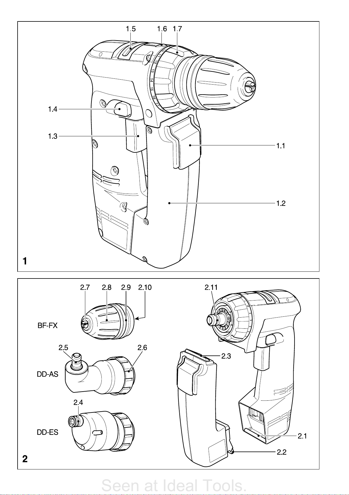
2.1 Remove battery pack from unit
The battery pack (1.2) is unlocked and can be
removed by pressing the switch (1.1)
downwards.
2.2 Charge battery pack
a) EC 60
The charger EC 60 (Fig. 4) can be used to
charge all NiCd-Festool battery packs between
7.2 V and 14.4 V.
Warning: Do not use the EC 60 charger to
charge NiMH battery packs as this will reduce
their service life.
The battery pack charging is monitored by
means of an NTC thermistor integrated in the
battery pack and a voltage measurement.
If the battery pack temperature is between
+ 5 and + 43 °C a quick charge starts
automatically.
Once the battery pack has been charged the
conservation charge starts automatically.
The LED (4.3) indicates the respective charging
state of the charger.
LED green - flashing = battery pack is being charged.
LED green - steady =
a) Device ready for use, though no battery
pack inserted.
b) Battery pack is fully charged, compensation
charge.
c) Battery temperature beyond permissible
limits. Charge continued automatically
when permis-sible temperature is reached.
If battery pack too warm, only a new start
of the charging process.
b) MCU 15
The charger MCU 15 (Fig. 3) can be used to
charge all Festool battery packs between 4.8 V
and 14.4 V in the battery chamber (3.1).
The battery type used (NiCd or NiMH) is
detected automatically.
Charging is controlled by a microprocessor.
Warning: If a warm NiMH battery pack
(>37°C) is inserted, charging will only be carried
out at a lower charge current.
In this case the charging time for a battery
pack with 3.0 Ah is around 100 min..
The following NiCd-battery packs can also be
charged in the battery chamber (4.2):
Bosch 7.2 V Part No. 260 73 00001
7.2 V Part No. 260 73 35020
9.6 V Part No. 260 73 00002
12.0 V Part No. 260 73 00000
AEG 7.2 V Part No. 318 460
9.6 V Part No. 325 100
MAKITA 7.2 V Part No. 19 16 79-9
9.6 V Part No. 19 16 81-2
9.6 V Part No. 19 20 19-4
The optimum charging current is always used
depending on the temperature, voltage and
internal resistance.
The two LEDs (3.3) indicate the respective
charging operation of the charger.
The right LED is the display for charging
chamber (3.1), the left LED for charging
chamber (3.2).
LED yellow - steady
= Charger is ready for use.
LED green - flashing
= Battery pack being charged.
LED green - fast flashing
= Battery pack being charged at max. charging
current.
LED green - steady
= Battery pack fully charged, conservation
charge on.
LED red - flash ing
= General malfunction, e. g. incorrect polarity
of battery pack, full contact not being made,
short-circuit, battery pack faulty.
LED red - steady
= Temperature of battery pack is outside
permissible limit.
If the battery pack is removed from the charging
chamber during charging, charging can only be
continued after 1-2 seconds when the LED
shows a steady yellow.
By the influence of powerful electromagnetic
perturbations while charging it can be switched
over to conservation charge. Thereby the
charger can not take in a dangerous or unsafe
status.
c) ECU 45
All N iC d an d N iM H b a tt er y p a ck s b et we e n 7.2 V
and 14.4 V voltage can be charged with the
ECU 45 charger (Fig. 4). The battery type used
(NiCd or NiMH) is detected automatically.
Charging is controlled by a microprocessor.
Warning: If a warm NiMH battery pack
(>37°C) is inserted, charging will only be carried
out at a lower charge current. In this case the
charging time for a battery pack with 3.0 Ah is
around 100 min.. The LED (4.3) shows the
charge status of the charger.
LED yellow - steady
= Charger is ready for use.
LED green - flashing
= Battery pack being charged.
LED green - fast flashing
= Battery pack being charged at max. charging
current.
LED green - steady
= Battery pack fully charged, conservation
charge on.
LED red - flashing
= General malfunction, e. g. incorrect polarity
of battery pack, full contact not being made,
short-circuit, battery pack faulty.
LED red - steady
= Temperature of battery pack is outside
permissible limit.
d) Charging with the EC 60, MCU 15
and ECU 45
Connect charger to mains. Warning: The line
voltage and frequency must correspond with
the data on the ratings plate!
10
Page 6

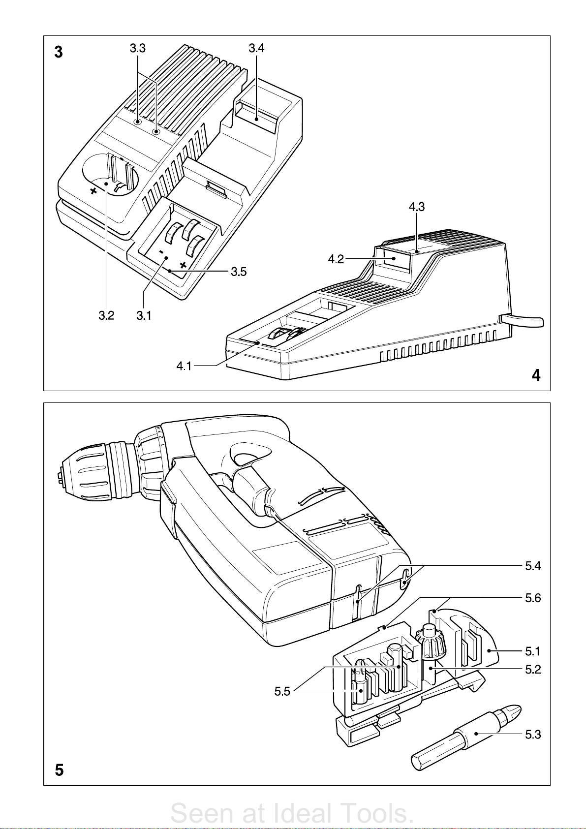
Insert battery pack into charging chamber:
Seen at Ideal Tools.
Insert battery pack with the fin (2.2) in the
lower groove (3.5 or 4.1) of the charging
chamber.
Push battery pack into charging chamber until
it catches with the lock (2.3) in the groove
(3.4 or 4.2). The battery pack is now charged.
Press the button (1.1) to unlock it and remove
it from the charger.
2.3 Fitting the battery pack in the tool
Place the charged battery pack with its fin (2.2)
in the groove (2.1). Push the battery pack
towards the tool until its lock (2.3) catches in
place. The cordless drill/screwdriver is now
ready for operation.
Warning: The cordless drill/screwdriver can be
operated with a battery pack whose voltage
is lower than the motor voltage of the cordless
drill/screwdriver, though not vice versa!
3 Initial operation
Turn on by pressing button (1 3).
Depending on the pressure exerted on the
button (1.3), the adjustment of running speed
can be varied infinitely.
Turn off by releasing the button (1.3).
After releasing the button, the chuck is stopped
and therefore, after-running of the equipment
is prevented.
3.1 To change the direction of rotation
The selector button (1.4) determines the
direction of rotation.
Turn button (1.4) from right to left
= clockwise rotation.
Turn button from left to right
= anticlockwise rotation .
Selector button in central position
= circuit interlock.
3.2 Shifting speeds
Warning!
Change only when completely stopped! Using
the shift lever (1.5), the speed can be changed.
If the shift lever cannot be switched completely,
slightly turn the chuck.
1. Speed: lever forward - Figure 1 is visible.
2. Speed: lever backwards - Figure 2 is visible.
3.3 Torque adjustment
By turning the adjustment ring (1.7), so that
the corresponding symbol aligns with the arrow
(1.6) the required torque can be adjusted.
a) Drilling
Drilling symbol on adjustment ring aligns with
the arrow = maximum torque.
b) Screws
Torque corresponding to setting:
Position 1 = low torque
Position 18 = high torque
4 Tool holding fixture, attachments
Caution: Make sure that the machine is
switched of and the battery block has been
removed before changing the tool holding
fixture, attachments and tools.
4.1 Chuck BF-FX
The chuck is used to clamp drills and bits.
a) Fitting/removing the chuck
Fitting
Place the chuck on the drill spindle (2.11)
and twist until the hexagon key (2.10) of
the chuck latches into the hexagon socket
of the drill spindle.
Pull the unlocking ring (2.9) forwards, press
the chuck onto the drill spindle up to the stop
and release the unlocking ring.
Removal
Pull the unlocking ring forwards and remove
the chuck.
b) Changing tools
Turn the clamping sleeve (2.8) anti-clockwise
to open the clamping jaws (2.7) (Note: the
spindle is automatically locked when the
machine is switched off).
Insert the tool into the chuck.
Clamp the tool by turning the clamping sleeve
clockwise. Always make sure that the tool is
clamped centrally in the chuck.
4.2 Angle attachment DD-AS
The angle attachment permits work (drilling,
screwing) vertical to the machines longitudinal axis.
a) Fitting/removing the angle attachment
Fitting
Place the angle attachment on the drill spindle
and turn until it catches in the desired position
(Note: The angle attachment can be fitted in
16 different angle settings).
Lock the angle attachment by turning the
fastening ring (2.6) tightly clockwise.
Removal
Turn the fastening ring anti-clockwise up to
the stop and remove the angel attachment.
b) Fitting/removal of chuck on angle
attachment
The chuck is fitted on the shaft (2.5) of the
angle attachment in the same way as on the
drill spindle of the machine.
4.3 Eccentric attachment DD-ES
The eccentric attachment is used to hold bits.
It allows screwing close to edges.
a) Fitting/removing the eccentric
attachment
The eccentric attachment is fitted/removed in
the same was as the angle attachment (see
Chapter 4.2 a.
b) Changing tools
Pull the unlocking ring (2.4) back and remove
the tool and/or insert the new tool.
11
Page 7

4.4 Tool holding fixture in the drill spindle
Seen at Ideal Tools.
Bits can be fitted directly in the hexagon socket
holder of the drill spindle (2.11) to make the
machine lighter and shorter.
5 Accessories, tools
The accessory and tool order number can be
found in the Festool catalogue or on the
Internet under www.festool.com.
Bit depot
Attachments which are used on a regular basis,
as for example the chuck key (5.2), bit
extender (5.3) or different bits (5.5), can be
clipped onto the bit depot compartment (5.1).
The bit depot can be snapped into the bottom
of the drill/screwdriver with its mounting lugs
(5.6).
When the mounting lugs are inserted into the
corresponding holes (5.4) and the magazine
is slid sideways the contour of the case aligns
with the contour of the magazine.
The spring loaded catch of the bit magazine
can loosen on impact of drill/screwdriver.
6 Wall mounting EC 60/ECU 45
The charger EC 60/ECU 45 has two longitudinal slots on its rear by which it can be
suspended on walls using two screws (e.g.
button-headed or flat head screw with a shaft
diameter of 5 mm).
Screw the screws into the wall so that their
heads protrude approx. 4 mm.
7 lnstructions on application -
maintenance - care
Important: please pay attention to the
following instructions. Otherwise there is a risk
of damage to the tool, charger or battery pack.
Keep the air vents of the electronic equipment
and the charger clean to guarantee the air
circulation for cooling.
Keep the connection contacts of electronic
equipment, charger and battery pack clean.
Festool chargers and Festool battery packs
are designed for each other. Therefore, only
use Festool chargers to charge Festool
battery packs.
By keeping the battery pack in a ready for
use charger, the battery pack will be kept in
a state of readiness by float charging
conservation.
Do not keep discharged battery pack
(maximum one month) attached to charger
whenever charger is detached from the
power supply (danger of deep discharging).
Whenever two battery packs are inserted into
the quick charger MCU 15 they will be
charged in the order of insertion.
A new battery pack or a battery pack not
used for a longer period of time reaches it
full capacity after about 5 charging and discharging cycles.
Battery packs should, before charging, be
fully discharged if possible. Continuous
starting of the charging process shortens the
lifespan of the batteries.
A co n siderably reduc ed time of operati on per
charging shows that the battery pack is used
up an should be replaced by a new one.
Store battery packs at ambient temperatures
between 0°C and 35°C.
All maintenance and repair work, requiring
dismantling of equipment, may only be
performed by an authorised after-sales
service workshop.
Special instructions for NiMH battery
packs:
Only charge NiMH battery packs in the
ECU 45, MCU 15 charger.
The output of NiMH battery packs drops
noticeably at ambient temperatures below
0°C or above 45°C.
Do not overload the tool (do not load the
tool excessively so that it comes to a
standstill).
Re-charge NiMH battery packs after 12
months even if they have not been used.
NiMH battery packs should be left for 60 min.
in the charger after every 10
compensate any differences in capacity
between the cells.
8 Recycling battery packs
Never throw spent battery packs into
domestic waste containers!
Return spent or defective battery packs to
dealers, the Festool after-sales service department or approved waste disposal facilities. This
ensures that they are correctly recycled.
9 Warranty
Our equipment is under warranty for at least
12 months with regard to material or
production faults in accordance with national
legislation. In the EU countries, the warranty
period is 24 months (an invoice or delivery
note is required as proof of purchase).
Damage resulting from, in particular, normal
wear and tear, overloading, improper handling,
or caused by the user or other damage caused
by not following the operating instructions, or
any fault acknowledged at the time of
purchase, is not covered by the warranty.
Complaints will only be acknowledged if the
equipment has not been dismantled before
being sent back to the suppliers or to an
authorised Festool customer support
workshop. Store the operating instructions,
safety notes, spare parts list and proof of
purchase in a safe place. In addition, the
manufacturers current warranty conditions
apply.
Note: We reserve the right to make changes
to the technical data contained in this
information as a result of ongoing research and
development work.
th
fast charge to
12
Page 8

EG-Konformitätserklärung. Wir erklären in alleiniger
Seen at Ideal Tools.
Verantwortung, dass dieses Produkt mit den
folgenden Normen oder normativen Dokumenten
übereinstimmt:
EN 50 144, EN 55 014, EN 61 000 gemäß den Bestimmungen
der Richtlinien 98/37/EG, 89/336/EWG.
CE-Konformitetserklæring. Vi erklærer på eget
ansvar at dette produktet er i overensstemmelse med
følgende normer eller normative dokumenter: EN 50 144,
EN 55 014, EN 61 000 i henhold til bestemmelsene i direktivene
98/37/EF, 89/336/EØF.
EC-Declaration of Conformity: We declare at our sole
responsibility that this product is in conformity with
the following standards or standardised documents:
EN 50 144, EN 55 014, EN 61 000 in accordance with the
regulations 98/37/EC, 89/336/EEC.
CE-Déclaration de conformité communautaire. Nous
déclarons sous notre propre responsabilité que ce
produit est conforme aux normes ou documents de
normalisation suivants: EN 50 144, EN 55 014, EN 61 000
conformément aux prescriptions des directives 98/37/CE,
89/336/CEE.
CE-Declaración de conformidad. Declaramos bajo
nuestra exclusiva responsabilidad que este
producto corresponde a las siguientes normas o documentos
normalizados: EN 50 144, EN 55 014, EN 61 000 conforme a
las prescripciones estipuladas en las directrices 98/37/CE,
89/336/CEE.
CE-Dichiarazione di conformità. Dichiariamo sotto
la nostra esclusiva responsabilità che il presente
prodotto è conforme alle norme e ai documenti normativi
seguenti: EN 50 144, EN 55 014, EN 61 000 conformemente
alle normative delle direttive 98/37/CE, 89/336/CEE.
CE-Declaração de conformidade: Declaramos, sob
a nossa exclusiva responsabilidade, que este
produto corresponde às normas ou aos documentos
normativos citados a seguir:
EN 50 144, EN 55 014, EN 61 000 segundo as disposições
das directivas 98/37/CE, 89/336/CEE.
Заявление о конформности СЕ. Мы заявляем в
единоличной ответственности, что данное изделие
соответствует требованиям следующих стандартов или
нормативов: EN 50 144, EN 55 014, EN 61 000 в соответствии
с постановлениями директив ЕС 98/37, ЕЭС 89/336.
Prohláení o souladu s normami CE. Prohlaujeme
na vlastní zodpovìdnost, e tento výrobek odpovídá
následujícím normám nebo normativním dokumentùm:
EN 50 144, EN 55 014, EN 61 000 v souladu s ustanoveními
smìrnic 98/37/EHS, 89/336/EHS.
Owiadczenie o zgodnoci CE. Niniejszym
owiadczamy z ca³¹ odpowiedzialnoci¹, ¿e wyrób
ten odpowiada nastêpuj¹cym normom wzglêdnie dokumentom
normatywnym: EN 50 144, EN 55 014, EN 61 000 zgodnie z
postanowieniami wytycznych 98/37/EG, 89/336/EWG.
EG-conformiteitsverklaring. Wij verklaren op eigen
verantwoordelijkheid dat dit produkt voldoet aan de
volgende normen of normatieve documenten. EN 50 144, EN
55 014, EN 61 000 conform de richtlijnen 98/37/EG,
89/336/EEG.
EG-konformitetsförklaring. Vi förklarar i eget ansvar,
att denna produkt stämmer överens med följande
normer och normativa dokument: EN 50 144, EN 55 014,
EN 61 000 enligt bestämmelserna i direktiven 98/37/EG,
89/336/EEG.
EY-standardinmukaisuusvakuutus. Vakuutamme
yksinvastuullisina, että tuote on seuraavien
standardien ja normatiivisten ohjeiden mukainen: EN 50 144,
EN 55 014, EN 61 000 direktiivien 98/37/EY, 89/336/EY
määräysten mukaan.
EF-konformitetserklæring: Vi erklærer at have alene
ansvaret for, at dette produkt er i overensstemmelse
med de følgende normer eller normative dokumenter:
EN 50 144, EN 55 014, EN 61 000 i henhold til bestemmelserne
af direktiverne 98/37/EF, 89/336/EØF.
CE-konformitás-nyilatkozat.Kizárólagos
felelõsségvállalás mellett ezennel tanúsítjuk, hogy
a jelen termék megfelel az alábbi szabványoknak ill.
szabványdokumentációnak: EN 50 144, EN 55 014,
EN 61 000 a 98/37EG, 89/336/EWG irányvonalak
rendelkezései szerint.
Дзлщуз ухммьсцщузт ЕК. Ме бнЬлзшз фзт
ухнплйкЮт ехиэнзт дзлюнпхме, ьфй фп рбсьн рспйьн
ухмцщнеЯ ме фб рбсбкЬфщ рсьфхрб кбй ме фб
рсьфхрб рпх бнбцЭспнфбй уфб учефйкЬ Эггсбцб ЕН 50 144,
ЕН 55 014, EN 61 000 уэмцщнб ме фпхт кбнпнйумпэт
98/37ЕК, 89/336/ЕПК
Leiter Forschung und Entwicklung
Manager Research and Development
Directeur de recherce et développement
Festool GmbH
Wertstr. 20
D-73240 Wendlingen
Dr. Johannes Steimel
455 789/200803
Page 9

Festool GmbH
Seen at Ideal Tools.
Postfach 1163
D-73236 Wendlingen
Wertstraße 20
D-73240 Wendlingen
) (07024) 804-0
Fax (07024) 804-608
http://www.festool.com
 Loading...