

Page 1
CDD 9.6 FX
CDD 12 FX
Instruction manual
Page 4
IMPORTANT: Read and understand all
instructions before using.
Guide dutilisation
Page 8
IMPORTANT: Lire et comprendre toutes les
instructions avant de démarrer les travaux.
Manual de instrucciones
Página 13
IMPORTANTE: Lea y comprende todas las
instrucciones antes de usar.
462069_002
1
Cordless Drill /
Screwdriver
Perceuse visseuse á
accumulateur
Taladradora-atornilladora
con acumuladores
Page 2
234
Page 3

Page 4

GENERAL SAFETY RULES
WARNING! Read and understand all
instructions. Failure to follow all instructions listed
below, may result in electric shock, fire and/or
serious personal injury.
SAVE THESE INSTRUCTIONS
Work area
1 Keep your work area clean and well lit.
Cluttered benches and dark areas invite accidents.
2 Do not operate tools in explosive
atmospheres, such as in the presence of
flammable liquids, gases, or dust. Tools create
sparks which may ignite the dust or fumes.
3 Keep bystanders, children, and visitors
away while operating a tool. Distractions can
cause you to lose control.
Electrical safety
4 A battery operated tool with integral
batteries or a separate battery pack must be
recharged only with the specified charger for
the battery. A charger that may be suitable for
one type of battery may create a risk of fire or
electric shock when used with another battery.
5 Use battery operated tool only with
specifically designated battery pack. Use of any
other batteries may create a risk of fire.
Personal safety
6 Stay alert, watch what you are doing and
use common sense when operating a tool. Do
not use while tired or under the influence of
drugs, alcohol, or medication. A moment of
inattention while operating tools may result in
serious personal injury.
7 Dress properly. Do not wear loose clothing
or jewellery. Contain long hair. Keep your hair,
clothing, and gloves away from moving parts.
Loose clothes, jewellery, or long hair can be caught
in moving parts.
8 Avoid accidental starting. Ensure switch is
in the off position before plugging in or
inserting battery pack. Carrying tools with your
finger on the switch or energising tools that have
the switch on invites accidents.
9 Remove adjusting keys or wrenches before
turning the tool on. A wrench or key that is left
attached to a rotating part of the tool may result in
personal injury.
10 Do not overreach. Stand on both feet an
keep proper footing and balance at all times.
Proper footing and balance enables better control
of the tool in unexpected situations.
11 Use safety equipment. Always wear eye
protection. Dust mask, non-skid safety shoes,
hard hat, or hearing protection must be used for
appropriate conditions.
12 If devices are provided for the connection
of dust extraction and collection facilities
ensure these are connected and properly used.
Use of these devices can reduce dust related
hazards.
Tool use and care
13 Use clamps or other practical way to secure
and support the workpiece to a stable
platform. Holding the work by hand or against
your body is unstable and may lead to loss of
control.
14 Do not force tool. Use the correct tool for
your application. The correct tool will do the job
better and safer at the rate for which it is designed.
15 Do not use tool if switch does not turn it
on or off. Any tool that cannot be controlled with
the switch is dangerous and must be repaired.
16 Disconnect battery pack from tool before
making any adjustments, changing
accessories, or storing the tool. Such preventive
safety measures reduce the risk of starting the tool
accidentally.
17 Store idle tools out of reach of children and
other untrained persons. Tools are dangerous
in the hands of untrained users.
18 When battery pack is not in use, keep it
away from other metal objects like: paper
clips, coins, keys, nails, screws, or other small
metal objects that can make a connection
from one terminal to another. Shorting the
battery terminals together may cause sparks,
burns, or a fire.
19 Maintain tools with care. Keep cutting tools
sharp and clean. Properly maintained tools, with
sharp cutting edges are less likely to bind and are
easier to control.
20 Check for misalignment or binding of
moving parts, breakage of parts, and any
other condition that may affect the tools
operation. If damaged, have the tool serviced
before using. Many accidents are caused by poorly
maintained tools.
21 Use only accessories that are
recommended by the manufacturer for your
model. Accessories that may be suitable for one
tool, may become hazardous when used on another
tool.
Service
22 Tool service must be performed only by
qualified repair personnel. Service or
maintenance performed by unqualified personnel
could result in a risk of injury.
23 When servicing a tool, use only identical
replacement parts. Follow instructions in the
Maintenance section of this manual. Use of
unauthorised parts or failure to follow Maintenance
instructions may create a risk of electric shock or
injury.
Page 5

Technical data
Cordless drill/screwdriver CDD 9.6 FX CDD 12 FX
Motor voltage 9.6 V 12 V
Idle-running speed 1. speed 0 380 rpm 0 - 380 rpm
2. speed 0 - 1100 rpm 0 - 1100 rpm
Max torque Soft boring (wood) 10 Nm 18 Nm
Hard boring (metal) 26 Nm 30 Nm
Adjustable torque 0.5 - 5 Nm 1 - 7 Nm
Chuck capacity 1 - 10 mm 1,5 - 13 mm
Max. drill diameter for metal / wood 12 mm / 20 mm 14 mm / 25 mm
Tool fitting in chuck 1/4 1/4
Weight with battery pack 1.8 kg (4.0 lbs) 2.0 kg (4.4 lbs)
Charger MC 15
Supply voltage (input) 120 V ~
Line frequency 60 Hz
Charging voltage (output) 4.8 - 12 V (DC)
Charging current quick charge max. 7.5 A
Compensation charge pulsating app. 0.03 A
Charging time for NiCd 1.4 Ah app. 13 min
NiCd 1.7 Ah app. 15 min
NiCd 2.0 Ah app. 18 min
Weight 0.9 kg (2.0 lbs)
Battery pack BPH 9.6 C BPH 12 C
Order number 488 437 488 438
Voltage 9.6 V 12 V
Cells 8 x 1.2 V, NiCd 10 x 1.2 V, NiCd
Capacity 2.0 Ah 2.0 Ah
Temp. range for charging 5 - 45 °C 5 - 45 °C
Monitoring of charge by means of NTC thermistor
Weight 0.5 kg (1.1 lbs) 0.6 kg (1.3 lbs)
The illustrations mentioned can be found at the beginning of the operating instructions.
1 Symbols
V volts
A amperes
Hz hertz
W watt
alternating current
n
0
no load speed
Class II Construction
rpm revolutions per minute
2 Intended use
The cordless drill/screwdrivers are suitable for
drilling metal, wood, plastic and similar materials,
as well as for fastening and screwing down of
screws with a diameter up to 6 mm.
The chargers have been designed to charge the
battery packs specified under 3.2.
The user will be liable for damage due to improper
use.
3 Preparation for initial operation
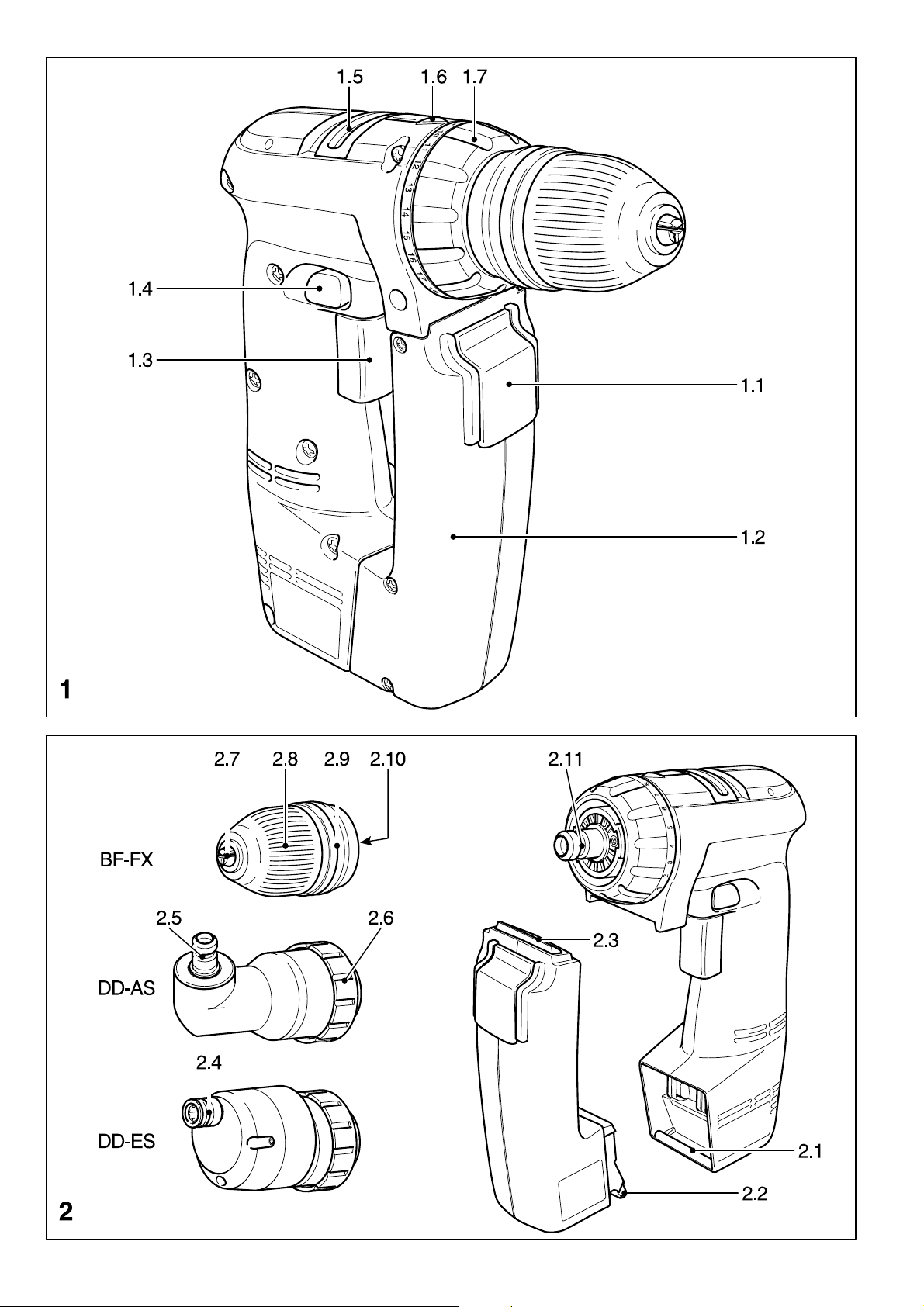
3.1 Remove battery pack from unit
The battery pack (1.2) is unlocked and can be
removed by pressing the switch (1.1) downwards.
3.2 Charge battery pack
a) MC 15
The charger MC 15 can be used to charge all
NiCd-FESTOOL battery packs between 4.8 V and
The charge process is controlled by a microprocessor. The optimum charging current is
always used depending on the temperature,
voltage and internal resistance.
The LED (3.2) indicates the respective charging
operation of the charger.
LED yellow - steady =
Charger is ready for use.
LED green - flashing =
Battery pack being charged.
LED green - fast flashing =
Battery pack being charged at max. charging
current.
LED green - steady =
Battery pack fully charged, conservation
charge on.
LED red - flashing =
General malfunction, e. g. incorrect polarity
of battery pack, full contact not being made,
short-circuit, battery pack faulty.
LED red - steady =
Temperature of battery pack is outside
permissible limit.
If the battery pack is removed from the charging
chamber during charging, charging can only be
continued after 1-2 seconds when the LED shows
a steady yellow.
12 V in the battery chamber (3.1).
5
Page 6

b) Charging with the MC 15
- Connect charger to mains. The line
voltage and frequency must correspond with
the data on the ratings plate!
- Insert battery pack with the fin (2.2) in the
lower groove (3.4) of the charging chamber.
- Push battery pack into charging chamber until
it catches with the lock (2.3) in the groove
(3.3).
The battery pack is now charged.
Press the button (1.1) to unlock it and remove it
from the charger.
3.3 Fitting the battery pack in the tool
- Place the charged battery pack with its fin (2.2)
in the groove (2.1).
- Push the battery pack towards the tool until
its lock (2.3) catches in place.
The cordless drill/screwdriver is now ready for
operation.
Note: The cordless drill/screwdriver can be
operated with a battery pack whose voltage is
lower than the motor voltage of the cordless drill/
screwdriver, though not vice versa!
4 Initial operation
Turn on by pressing button (1 3). Depending on
the pressure exerted on the button, the
adjustment of running speed can be varied
infinitely.
Turn off by releasing the button. After releasing
the button, the chuck is stopped and therefore,
after-running of the equipment is prevented.
4.1 To change the direction of rotation
The selector button (1.4) determines the direction
of rotation.
- Turn button from right to left = clockwise
rotation.
- Turn button from left to right = anticlockwise
rotation.
- Selector button in central position = circuit
interlock.
4.2 Shifting speeds
Change only when completely
stopped! Using the shift lever (1.5), the speed
can be changed. If the shift lever cannot be
switched completely, slightly turn the chuck.
1. Speed: lever forward - Figure 1 is visible.
2. Speed: lever backwards - Figure 2 is visible.
4.3 Torque adjustment
By turning the adjustment ring (1.7), so that the
corresponding symbol aligns with the arrow (1.6)
the required torque can be adjusted.
a) Drilling:
Drilling symbol on adjustment ring aligns with
the arrow = maximum torque.
b) Screws:
Torque corresponding to setting:
Position 1 = low torque
Position 18 = high torque
5 Tool holding fixture, attachments
Make sure that the machine is
switched of and the battery block has been
removed before changing the tool holding fixture,
attachments and tools.
5.1 Chuck BF-FX
The chuck is used to clamp drills and bits.
5.1.1 Fitting / removing the chuck
Fitting:
- Place the chuck on the drill spindle (2.11) and
twist until the hexagon key (2.10) of the chuck
latches into the hexagon socket of the drill
spindle.
- Pull the unlocking ring (2.9) forwards, press
the chuck onto the drill spindle up to the stop
and release the unlocking ring.
Removal:
- Pull the unlocking ring forwards and remove
the chuck.
5.1.2 Changing tools
- Turn the clamping sleeve (2.8) anti-clockwise
to open the clamping jaws (2.7) (Note: the
spindle is automatically locked when the
machine is switched off).
- Insert the tool into the chuck.
- Clamp the tool by turning the clamping sleeve
clockwise. Always make sure that the tool is
clamped centrally in the chuck.
5.2 Angle attachment DD-AS
The angle attachment permits work (drilling,
screwing) vertical to the machines longitudinal
axis.
5.2.1 Fitting / removing the angle attach-
ment
Fitting:
- place the angle attachment on the drill spindle
and turn until it catches in the desired position
(Note: The angle attachment can be fitted in
16 different angle settings).
- Lock the angle attachment by turning the
fastening ring (2.6) tightly clockwise.
Removal:
- Turn the fastening ring anti-clockwise up to
the stop and remove the angel attachment.
5.2.2 Fitting / removal of chuck on angle
attachment
The chuck is fitted on the shaft (2.5) of the angle
attachment in the same way as on the drill spindle
of the machine.
5.3 Eccentric attachment DD-ES
The eccentric attachment is used to hold bits. It
allows screwing close to edges.
5.3.1 Fitting / removing the eccentric
attachment
The eccentric attachment is fitted / removed in
the same was as the angle attachment (see
Chapter 5.2.1).
6
Page 7

5.3.2 Changing tools
- Pull the unlocking ring (2.4) back and remove
the tool and/or insert the new tool.
5.4 Tool holding fixture in the drill spindle
Bits can be fitted directly in the hexagon socket
holder of the drill spindle (2.11) to make the
machine lighter and shorter.
6 Accessories, tools
The accessory and tool order number can be
found in the Festool catalogue or on the Internet
under "www.festool.com".
Bit depot
Attachments which are used on a regular basis,
as for example the chuck key (4.2), bit extender
(4.3) or different bits (4.5), can be clipped onto
the bit depot (4.1).
The bit depot can be snapped into the bottom
of the drill/screwdriver with its mounting lugs
(4.6). When the mounting lugs are inserted into
the corresponding holes (4.4) and the magazine
is slid sideways the contour of the case aligns
with the contour of the magazine.
The spring loaded catch of the bit magazine can
loosen on impact of drill/screwdriver.
7 lnstructions on application -
maintenance - care
Please pay attention to the following
instructions. Otherwise there is a risk of damage
to the tool, charger or battery pack.
Keep the air vents of the electronic equipment
and the charger clean to guarantee the air
circulation for cooling.
Keep the connection contacts of electronic
equipment, charger and battery pack clean.
Festool chargers and Festool battery packs
are designed for each other. Therefore, only
use Festool chargers to charge Festool battery
packs.
By keeping the battery pack in a ready for use
charger, the battery pack will be kept in a state
of readiness by float charging conservation.
Do not keep discharged battery pack
(maximum one month) attached to charger
whenever charger is detached from the power
supply (danger of deep discharging).
A new battery pack or a battery pack not used
for a longer period of time reaches it's full
capacity after about 5 charging and discharging
cycles.
Battery packs should, before charging, be fully
discharged if possible. Continuous starting of
the charging process shortens the lifespan of
the batteries.
A considerably reduced time of operation per
charging shows that the battery pack is used
up an should be replaced by a new one.
Store battery packs at ambient temperatures
between 0°C and 35°C.
All maintenance and repair work, requiring
dismantling of equipment, may only be
performed by an authorised after-sales service
workshop.
8 Recycling battery packs
Never throw spent battery packs into
domestic waste containers! Return spent or
defective battery packs to dealers, the Festool
after-sales service department or approved waste
disposal facilities. This ensures that they are
correctly recycled.
9 Warranty
Festool warrants, that all Festool portable power
tools will be free from defects in materials and
workmanship for a term of one year from the date
of procurement. Festool makes no other warranty,
express or implied, for all Festool portable power
tools. No agent, representative, distributor, dealer,
or employee of Festool has the authority to
increase or otherwise change the obligations or
limitations of this warranty. The obligations of
Festool in its sole discretion under this warranty
shall be limited to the repair or replacement of
any Festool portable power tool which is found to
be defective as packaged with this User Manual.
Excluded from the coverage under this warranty
are: normal wear and tear; damages caused by
misuse, abuse or neglect; damage caused by
anything other than defects in material and
workmanship.
Returning product: Call us for authorisation.
For product returns: (888) 463-3786
For service or repairs: (800) 554-8741
We will supply you with the correct address for
your return. This is important because not all types
of returns are to be shipped to the same address.
IN NO EVENT SHALL FESTOOL BE LIABLE FOR
ANY CONSEQUENTIAL OR INCIDENTAL DAMAGES
FOR BREACH OF THIS OR ANY OTHER WARRANTY,
EXPRESSED OR IMPLIED WHATSOEVER.
ALL WARRANTIES IMPLIED BY STATE LAW,
INCLUDING THE IMPLIED WARRANTIES OF
MERCHANTABILITY AND FITNESS FOR A
PARTICULAR PURPOSE, ARE HEREBY LIMITED TO
THE DURATION OF ONE YEAR.
Some states in the U.S. and some Canadian
provinces do not allow the limitations on how long
an implied warranty lasts, so the above limitation
may not apply to you. With the exception of any
warranties implied by state or province law as
hereby limited, the foregoing express limited
warranty is exclusive and in lieu of all other
warranties, guarantees, agreements and similar
obligations of Festool.
This warranty gives you specific legal rights and
you may also have other rights which vary from
state to state in the U.S. and province to province
in Canada.
7
Page 8

RÉGLES DE SÉCURITÉ GÉNÉRALES
AVERTISSEMENT! Vour devez lire et
comprendre toutes les instructions. Le non-
respect, même partiel, des instructions ci-après
entraîne un risque de choc électrique, dincendie et/
ou de blessures graves.
CONSERVEZ CES INSTRUCTIONS
Aire de travail
1 Veillez à ce que laire de travail soit propre
et bien éclairée. Le désordre et le manque de
lumière favorisent les accidents.
2 Nutilisez pas doutils électriques dans une
atmosphère explosive, par exemple en
présence de liquides, de gaz ou de poussières
inflammables. Les outils électriques créent des
étincelles qui pourraient enflammer les poussières
ou les vapeurs.
3 Tenez à distance les curieux, les enfants et
les visiteurs pendant que vous travaillez avec
un outil électrique. Ils pourraient vous distraire et
vous faire une fausse manoeuvre.
Sécurité électrique
4 Un outil à bloc-batterie amovible ou a
batterie intégrée ne doit être recharge quavec
le chargeur prévu pour la batterie. Un chargeur
qui convient à tel type de batterie peut présenter un
risque dincendie avec tel autre de batterie.
5 Nutilisez un outil quavec un bloc-batterie
conçu spécifiquement pour lui. Lemploi dun autre
bloc-batterie peut créer un risque dincendie.
Sécurité des personnes
6 Restez alerte, concentrez-vous sur votre
travail et faites preuve de jugement. Nutilisez
pas un outil électrique si vous êtes fatigué ou
sous linfluence de drogues, dalcool ou de
médicaments. Un instant dinattention suffit pour
entraîner des blessures graves.
7 Habitiez-vous convenablement. Ne portez ni
vêtements flottants ni bijoux. Confinez les
cheveux longs. Napprochez jamais les
cheveux, les vêtements ou les gants des pièces
en mouvement. Des vêtement flottants, des bijoux
ou des cheveux longs risquent dêtre happés par
des pièces en mouvement.
8 Méfiez-vous dun démarrage accidentel.
Avant de brancher loutil, assurez-vous que son
interrupteur est sur ARRÊT. Le fait de transporter
un outil avec le doigt sur la détente ou de brancher
un outil dont linterrupteur est en position MARCHE
peut mener tout droit à un accident.
9 Enlevez les clés de réglage ou de serrage
avant de démarrer loutil. Une clé laissée dans
une pièce tournante de loutil peut provoquer des
blessures.
10 Ne vous penchez pas trop en avant.
Maintenez un bon appui et restez en équilibre
en tout temps. Un bonne stabilité vous permet de
mieux réagir à une situation inattendue.
11 Utilisez des accessoires de sécurité. Portez
toujours des lunettes ou une visière. Selon les
conditions, portez aussi un masque antipoussière,
des bottes de sécurité antidérapantes, un casque
protecteur et/ou un appareil antibruit.
12 Assurez-vous que les dispositifs existants
sont bien raccordés à laspiration et au captage
des poussières, et quils sont correctement
utilisés. Lutilisation de ces dispositifs permet de
réduire les dangers provenant des poussières.
Utilisation et entretien des outils
13 Immobilisez le matériau sur une surface
stable au moyen de brides ou de toute autre
façon adéquate. Le fait de tenir la pièce avec la
main ou contre votre corps offre une stabilité
insuffisante et peut amener un dérapage de loutil.
14 Ne forcez pas loutil. Utilisez loutil appropríé
à la tâche. Loutil correct fonctionne mieux et de
façon plus sécuritaire. Respectez aussi la vitesse de
travail qui lui est propre.
15 Nutilisez pas un outil si son interrupteur est
bloqué. Un outil que vous ne pouvez pas commander
par son interrupteur est dangereux et doit être
réparé.
16 Retirez le bloc-batterie avant deffectuer un
réglage, de changer daccessoire ou de ranger
loutil. De telles mesures pré-ventives de sécurité
réduisent le risque de démarrage accidentel de loutil.
17 Rangez les outils hors de la portée des
enfants et dautres personnes inexpérimentées.
Les outils sont dangereux dans les mains
dutilisateurs novices.
18 Lorsque le bloc-batterie nest pas en service,
tenez-le à lécart dautres objets métalliques /
trombones, pièces de monnaie, clés, clous, vis,
etc.) susceptibles détablir un contact électrique
entre les deux bornes. La mise en court-circuit
des bornes de la batterie peut produire des étincelles
et constitue un risque de brûlures ou dincendie.
19 Prenez soin de bien entretenir les outils. Les
outils de coupe doivent être toujours bien
affûtés et propres. Des outils bien entretenus, dont
les arêtes sont bien tranchantes, sont moins
susceptibles de coincer et plus faciles à diriger.
20 Soyez attentif à tout désalignement ou
coincement des pièces en mouvement, à tout
bris ou à toute autre condition préjudiciable au
bon fonctionnement de loutil. Si vous constatez
quun outil est endommagé, faites-le réparer
avant de vous en servir. De nombreux accidents
sont causés par des outils en mauvais état.
21 Nutilisez que des accessoires que le
fabricant recommande pour votre modèle
doutil. Certains accessoires peuvent convenir à un
outil, mais être dangereux avec un autre.
Réparation
22 La réparation des outils électriques doit être
confiée à un réparateur qualifié. Lentretien ou
8
Page 9

la réparation dun outil électrique par un amateur
peut avoir des conséquences graves.
23 Pour la réparation dun outil, nemployez que
des pièces de rechange dorigine. Suivez les
directives données à la section Réparation de
ce manuel. Lemploi de pièces non autorisées ou le
non-respect des instructions dentretien peut créer
un risque de choc électrique ou de blessures.
Caractéristiques techniques
Perceuse-visseuse CDD 9.6 FX CDD 12 FX
Tension du moteur 9.6 V 12 V
Vitesse à vide 1ère vitesse 0-380 tr/min 0-380 tr/min
2ème vitesse 0-1100 tr/min 0-1100 tr/min
Couple de rotation max.
cas de vissage dans un matériau tendre (bois) 10 Nm 18 Nm
cas de vissage dans un matériau dur (métal) 26 Nm 30 Nm
Réglage de couple 0.5 - 5 Nm 1 - 7 Nm
Capacité mandrin 1 - 10 mm 1.5 - 13 mm
Maxi capacité de perçage dans du métal / du bois 12 mm / 20 mm 14 mm / 25 mm
Raccordement doutil dans la broche de perçag ¼ " ¼ "
Poids avec accumulateur 1.8 kg (4.0 lbs) 2.0 kg (4.4 lbs)
Chargeur MC 15
Tension secteur (entrée) 120 V ~
Fréquence secteur 60 Hz
Tension de charge (sortie) 4.8 - 12 V (DC)
Courant de charge, charge rapide 7.5 A max.
Charge de maintien à impulsions, environ 0.03 A
Durée de charge pour NiCd 1.4 Ah 13 mn. env.
NiCd 1.7 Ah 15 mn. env.
NiCd 2.0 Ah 18 mn. env.
Poids 0.9 kg (2.0 lbs)
Accumulateur BPH 9.6 C BPH 12 C
Référence 488 437 488 438
Tension 9.6 V 12 V
Piles 8 x 1.2 V, NiCd 10 x 1.2 V, NiCd
Capacité 2.0 Ah 2.0 Ah
Plage de température de charge 5 - 45°C 5 - 45°C
Contrôle détat de charge via résistance NTC
Poids 0.5 kg (1.1 lbs) 0.6 kg (1.3 lbs)
Les représentations indiquées figurent au début du mode demploi.
1 Symbole
V Volt
A Ampère
Hz Hertz
W Watt
Tension alternative
n
0
Vitesse de rotation à vide
Classe II conception
tr/min tours par minute
2 Utilisation conforme aux prescriptions
Les perceuses-visseuses à accumulateur se
prêtent à percer le métal, le bois, les matières
plastiques et des matériaux semblables ainsi quà
visser à fond et introduire des vis jusquà 6 mm
de diamètre.
Les chargeurs sont destinés à charger les accumulateurs rechargeables indiqués au chapitre 3.2.
Seul lutilisateur est tenu responsable des
3 Préparatifs de mise en service
3.1 Enlever laccumulateur de lappareil
En appuyant sur la touche (1.1), laccumulateur
(1.2) se trouve déverrouillé et peut alors être
enlevé.
3.2 Charger laccumulateur
a) MC 15
Le chargeur MC 15 permet de charger tous les
NiCd-accumulateurs FESTOOL dun voltage entre
4.8 et 12 dans le compartiment de charge (3.1).
Lopération de chargement est pilotée par micro-
processeur. En fonction de la température, de la
tension et de la résistance interne, cest toujours
le courant de charge optimal qui se règle.
La DEL (3.2) indiquent létat de service actuel du
chargeur.
DEL jaune - éclairage continu =
le chargeur est prêt à fonctionner.
dommages qui résulteraient dune utilisation non
conforme aux prescriptions.
9
Page 10

DEL verte - éclairage clignotant =
laccumulateur est en train dêtre chargé.
DEL verte - clignotement rapide =
laccumulateur est en train dêtre chargé en
courant de charge max.
DEL verte - éclairage continu =
laccumulateur est chargé; la charge de
maintien est active.
DEL rouge - éclairage clignotant =
indication derreur générale, par exemple
polarité inversée de laccumulateur, pas de
mise en contact complète, court-circuit,
défectuosité de laccumulateur
DEL rouge - éclairage continu =
température de laccumulateur au-delà des
valeurs limites admissibles.
Au cas où laccumulateur serait enlevé de son
com-partiment en cours de chargement,
lopération de chargement ne pourra se
poursuivre quaprès un temps dattente denviron
1 à 2 s, une fois que la DEL présentera un
éclairage jaune continu.
b) Opération de chargement MC 15
- Brancher le chargeur au secteur.
La tension secteur et la
fréquence doivent correspondre aux indications
sur la plaque signalétique!
- Suspendre laccumulateur avec la nervure
(2.2) dans lévidement inférieur (3.4) du
compartiment de charge.
- Pousser laccumulateur dans le compartiment
de charge jusquà ce quil senclenche avec le
verrouillage (2.3) dans lévidement (3.3).
Dès maintenant, laccumulateur est en train dêtre
chargé.
En appuyant sur la touche (1.1), laccumulateur
peut être déverrouillé et enlevé du chargeur.
3.3 Mise en place de laccumulateur dans
lappareil
- Suspendre laccumulateur chargé avec la
nervure (2.2) dans lévidement (2.1).
- Pousser laccumulateur en direction de la
machine jusquà ce quil senclenche avec le
verrouillage (2.3) dans lappareil.
Dès à présent, la perceuse-visseuse à
accumulateur est prête à fonctionner.
Remarque: Il est possible dexploiter la
perceuse-visseuse avec un accumulateur qui
présente une tension moins importante que son
moteur, ce qui nest cependant pas possible si la
tension de laccumulateur surpasse la tension du
moteur.
4 Mise en service
Mise en marche en appuyant sur la touche de
commutation (1.3). La vitesse de rotation peut
être progressivement réglée, en fonction du mode
de pression sur la touche de commutation.
Mise à larrêt en relâchant la touche de
commutation. Une fois que la touche de
commutation est relâchée, la broche de travail
(mandrin) est freinée, ce qui empêche ainsi une
poursuite de rotation par inertie de loutil.
4.1 Commutation du sens de rotation
Le bouton de commutation (1.4) sert à déterminer le sens de rotation.
- Bouton poussé de droite vers la gauche =
marche à droite.
- Bouton poussé de gauche vers la droite =
marche à gauche.
- Bouton en position centrale = verrouillage de
mise en marche.
4.2 Commutation de lengrenage
Procéder à la commutation
uniquement à larrêt ou en fin de roulement.
Le curseur de commutation (1.5) permet de
commuter lengrenage. Si le curseur de
commutation ne peut pas être déplacé jusquà la
butée, il convient dans ce cas de tourner un peu
la broche de perçage.
1ère vitesse: curseur de commutation vers
lavant - le chiffre 1 est visible.
2ème vitesse: curseur de commutation vers
larrière- le chiffre 2 est visible.
4.3 Réglage du couple de rotation
Il est possible de faire varier le couple de rotation
en tournant la bague de réglage (1.7). La flèche
apposée (1.6) indiquera létat réglé.
a) Perçage:
couple de rotation maximal - la flèche est pointée
sur le symbole de perçage
b) Vissage:
couple de rotation en fonction du réglage:
position sur 1 = couple de rotation réduit
position sur 18 = couple de rotation élevé
5 Porte-outil, groupes d'appui
A chaque remplacement du porteoutil, du groupe d'appui et de l'outil, assurezvous que la machine est convenablement
inactivée et que l'accumulateur est enlevé.
5.1 Mandrin de perceuse BF-FX
Le mandrin de perceuse sert à serrer les forets
et les embouts.
5.1.1 Montage / démontage du mandrin de
perceuse
Montage:
- Placez le mandrin de perceuse sur l'axe (2.11)
puis tournez-le jusqu'à ce que le six pans
(2.10) du mandrin de perceuse s'enclenche
dans le logement de l'axe.
- Tirez la bague de déverrouillage (2.9) vers
l'avant, enfoncez le mandrin de perceuse jusqu'à la butée sur l'axe puis relâchez la bague
de déverrouillage.
Démontage :
- Tirez la bague de déverrouillage vers l'avant
puis enlevez le mandrin de perceuse.
10
Page 11

5.1.2 Changement d'outil
- Tournez la douille de serrage (2.8) dans le sens
contraire des aiguilles d'une montre pour ouvrir
les mâchoires de serrage (2.7) (Remarque : A
machine inactivée, l'axe est automa-tiquement
verrouillé).
- Placez l'outil dans le mandrin de perceuse.
- Serrez l'outil à fond en tournant la douille de
serrage dans le sens des aiguilles d'une
montre. Ce faisant, veillez toujours à ce que
l'outil soit serré au centre du mandrin.
5.2 Appui angulaire DD-AS
L'appui angulaire permet de travailler (percer,
visser) à la verticale par rapport à l'axe longitudinal de la machine.
5.2.1 Montage / démontage de l'appui
angulaire
Montage :
- Placez l'appui angulaire sur l'axe et tournez-le
jusqu'à ce qu'il s'enclenche dans la position
souhaitée (Remarque : L'appui angulaire peut
s'enclencher dans 16 positions angulaires
différentes).
- Verrouillez l'appui angulaire en tournant
fermement la bague de fixation (2.6) dans le
sens des aiguilles d'une montre.
Démontage :
- Tournez la bague de fixation dans le sens
contraire des aiguilles d'une montre jusqu'à la
butée puis enlevez l'appui angulaire.
5.2.2 Montage / démontage du mandrin de
perceuse sur l'appui angulaire
Le mandrin de perceuse doit être fixé de la même
manière sur l'arbre (2.5) de l'appui angu-laire
que sur l'axe de la machine.
5.3 Appui excentrique DD-ES
L'appui excentrique sert à la réception d'embouts.
Il permet de visser à proximité du bord.
5.3.1 Montage / démontage de l'appui
excentrique
Le montage / démontage de l'appui excentrique
s'opère de la même manière que pour l'appui
angulaire (cf. chapitre 5.2.1).
5.3.2 Changement d'outil
- Tirez la bague de déverrouillage (2.4) vers
l'arrière puis enlevez l'outil ou resp. mettez
un outil en place.
5.4 Porte-outil sur l'axe
Afin que la machine devienne plus légère et plus
courte, les embouts peuvent être mis en place
directement dans le logement six pans de l'axe
(2.11).
6 Accessoires, outils
Les références des accessoires et outils figurent
dans le catalogue Festool ou sur Internet sous
"www.festool.com".
Bit-Depot
Afin que les pièces fréquemment utilisées comme
par exemple les clés de mandrin (4.2), la rallonge
de bit (4.3) ou différents bits (4.5) soient toujours
à portée de la main, ces pièces peuvent être
clipsées dans le Bit-Depot (4.1).
Le Bit-Depot, cest-à-dire la réserve à accessoires, peut être fixé par ses nez de retenue (4.6)
sur la partie inférieure de la perceuse-visseuse.
Ce faisant, les nez de retenue doivent être
introduits dans les ouvertures présentes (4.4).
Après quoi, le Bit-Depot doit être déplacé
latéralement, de sorte que le contour du boîtier
et que le contour du Bit-Depot coïncident.
Une force de choc entre la perceuse-visseuse et
le Bit-Depot risque douvrir le fermoir.
7 Informations de travail - Entretien
Il est indispensable dobserver les
consignes suivantes, sinon, la machine, le
chargeur ou laccumulateur risque dêtre
endommagé(e).
Veiller à ce que les ouvertures daération sur
loutil électrique et sur le chargeur soient
toujours propres afin que la circulation de lair
de refroidissement soit assurée.
Veiller à ce que les contacts de raccordement
sur loutil électrique, sur le chargeur et sur
laccu-mulateur soient toujours propres.
Les chargeurs Festool et les accumulateurs
Festool sont conçus en parfaite harmonie
conceptuelle, cest pourquoi il convient de
charger les accumulateurs Festool uniquement
avec des chargeurs Festool.
En laissant laccumulateur dans le chargeur prêt
à fonctionner, laccumulateur est conservé en
état chargé grâce à un chargement de maintien
permanent.
Ne pas laisser les accumulateurs vides enfichés
pendant plus dun mois env. dans le chargeur
lorsque le chargeur est coupé du secteur
(risque de décharge profonde).
Un accumulateur neuf ou nayant pas été utilisé
pendant une longue période natteint sa pleine
capacité quau bout de 5 cycles de charge et
de décharge environ.
Il faudrait, dans la mesure du possible, que
les accumulateurs soient entièrement
déchargés avant dêtre rechargés. En effet, un
démarrage réitéré de lopération de charge
daccumulateurs chargés diminue leur durée
de vie.
Une durée de fonctionnement considérable-
ment plus réduite à la suite de chaque recharge
indique que l'accumulateur est usé et qu'il doit
par conséquent être remplacé par un neuf.
Les accumulateurs doivent être stockés à des
températures ambiantes entre 0° C et 35° C.
Tous travaux dentretien et de réparation
exigeant que les appareils soient ouverts
doivent être uniquement exécutés par un
atelier de service après-vente autorisé.
11
Page 12

8 Recyclage des accumulateurs
Ne pas jeter les accumulateurs usagées dans
les ordures ménagères. Les accumulateurs
usagés ou défectueux doivent être rendus aux
revendeurs, au service après-vente Festool ou
aux installations délimination publiques
prescrites. Les accumulateurs seront ainsi soumis
à un recyclage approprié.
9 Garantie
Festool donne une garantie sur tous les
instruments portables électriques, sur les défauts
ou la qualité du matériel pour la période dun an,
à partir de la date dachat. Festool ne donne
aucune garantie supplémentaire, ni de manière
expressive ni silencieuse sur les instruments portables électriques Festool. Aucun agent,
représentant commercial, distributeur, vendeur
ou employé de Festool nest autorisé à prolonger
ou à changer les obligations ou restrictions de
cette garantie. Les obligations de Festool selon
sa propre appréciation et les termes de cette
garantie sont limitées à la réparation ou échanges
des instruments portables électriques Festool, qui
sont défectueux et emballés avec ce mode
demploi. Cette garantie exclue la couverture des
dommages suivants: usures et fissures à lusage;
dommages causés par mauvais traitement, abus
ou négligences; dommages nétant ni dépendant
de défauts du matériel ni de sa qualité.
Renvoi des produits: Appelez-nous pour
lautorisation.
Pour des retours de produit: (888) 463-3786
Pour le service ou les réparations: (800) 554-8741
Nous vous fournirons ladresse correcte pour
votre retour. Cest important parce que pas tous
les types de retours doivent être transportés à
la même adresse.
FESTOOL NEST EN AUCUN CAS RESPONSABLE
DES DOMMAGES RÉSULTANT OU CONSÉCUTIFS
DE CASSE OU QUELQUE AUTRE GARANTIE QUE
CE SOIT, NI DONNÉE EXPRESSIVEMENT NI
SILENCIEUSEMENT.
TOUTES LES GARANTIES RÉGLÉES PAR LA LOI,
COMPRENANT LES GARANTIES DE
MARCHANDISE ET LES CONDITIONS
PARTICULIÈRES DACHAT SONT LIMITÉES ICI À
LA PÉRIODE DUN AN.
Certains états doutre-Atlantique et certaines
provinces du Canada interdisent les limitations
de temps de garantie, si bien que les restrictions
ci-dessus décrites, nentrent pas en vigueur pour
ces régions. À lexception de certaines garanties
applicables par diverses lois de certains états ou
provinces ci-dessus nommés, les conditions de
garantie ici-décrites sont exclusives, sont en
vigueur et remplacent toutes autres garanties,
conventions et obligations similaires de Festool.
Cette garantie vous donne des droits légaux
spécifiques et vous avez également des droits
supplémentaires variants dun état à lautre aux
Etats-Unis et dune province à lautre au Canada.
12
Page 13

NORMAS GENERALES DE SEGURIDAD
¡AVISO! Lea y entienda todas las
instrucciones. El incumplimiento de una sola de
las instrucciones aquí listadas, puede tener como
resultado una descarga eléctrica, fuego y/o lesiones
personales serias.
CONSERVE ESTAS INSTRUCCIONES
Espacio de trabajo
1 Mantenga su espacio de trabajo limpio y
bien iluminado. Bancos de trabajo desordenados
y areas oscuras facilitan accidentes.
2 No maneje herramientas en ambientes
explosivos, como por ejemplo en presencia
de líquidos inflamables, gases, o polvo. Las
herramientas generan chispas que pueden
encender el polvo o gases.
3 Mantenga espectadores, niños, y visitantes
fuera del alcance mientras maneje
herramientas. Distracciones pueden causarle la
pérdida del control.
Seguridad eléctrica
4 Una herramienta accionada por
acumuladores con acumulador incorporado o
acumulador por separado solamente se
deberá cargar con el cargador previsto para
este acumulador. Un cargador que es adecuado
para un tipo de acumulador concreto puede producir
fuego o choque eléctrico, si se utiliza con otro tipo
de acumulador.
5 Emplee las herramientas accionadas por
acumuladores solamente con el paquete de
acumuladores previsto especialmente para
ellas. El uso de cualquier otro tipo de acumulador
puede ser la causa de que se produzca un incendio.
Seguridad personal
6 Manténgase atento, observe lo que está
haciendo y use el sentido común cuando use
una herramienta. No trabaje estando cansado
o bajo influencia de drogas, alcohol, o
medicamentos. Un momento sin prestar atención
mientras maneja una herramienta puede tener
como resultado serias lesiones personales.
7 Vístase apropiadamente. No lleve ropa
suelta o joyas. Sujete pelo largo. Mantenga
su pelo, ropa y guantes fuera del alcance de
partes movibles. Ropa, joyas y pelo suelto pueden
pillarse en partes movibles.
8 Evite accidentes al iniciar. Asegúrese que
el interruptor está apagado antes de enchufar.
Transportar herramientas con el dedo en el
interruptor o enchufar las herramientas con el
interruptor encendido puede provocar accidentes.
9 Quite llaves de ajuste o conmutadores
antes de encender la herramienta. Una llave
inglesa u otra llave que se deja puesta en partes
rotatorias de la herramienta pueden causar lesiones
personales.
10 No exceda límites. Mantenga estabilidad y
balance apropiado en todo momento.
Estabilidad y balance apropiado posibilitan el mejor
control de la herramienta en situaciones
inesperadas.
11 Use equipamiento de seguridad. Lleve
siempre gafas protectoras. Mascarilla de polvo,
zapatos de seguridad antirresbaladizos, casco, o
protección de los oídos deben ser utilizados para
condiciones adecuadas.
12 Confirme que las conexiones existentes
para la aspiración de polvo y para el
dispositivo recogedor están conectadas y que
se emplean debidamente. El uso de estos dis-
positivos puede reducir peligros relacionados polvo.
Uso y cuidado de la herramienta
13 Use abrazaderas u otras formas prácticas
de sujetar y asegurar la pieza de trabajo en
una plataforma estable. Sujetar la pieza de
trabajo con la mano o contra el cuerpo es inestable
y puede causar la pérdida de control.
14 No fuerce la herramienta. Use la
herramienta correcta para su aplicación. La
herramienta correcta hará su trabajo de manera
mejor y más segura al nivel para el cual está
diseñada.
15 No use la herramienta si el interruptor no
la enciende y apaga. Cualquier herramienta que
no se pueda controlar por el interruptor es peligrosa
y debe ser arreglada.
16 Retire el paquete de acumuladores de la
herramienta, antes de proceder a cualquier
tipo de ajustes, así como antes de un cambio
de accesorios o del depósito de la herramienta
en almacén. Estas medidas preventivas de
seguridad reducen el riesgo de poner en
funcionamiento la herramienta accidentalmente.
17 Guarde herramientas desocupadas fuera
del alcance de niños u otras personas sin
experiencias. Las herramientas son peligrosas en
manos de personas inexpertas.
18 Cuando no lo utilice, mantenga el paquete
de acumuladores alejado de otras piezas u
objetos metálicos como, por ejemplo, grapas,
sujetapapeles, monedas, llaves, clavos, tornillos u otras piezas metálicas pequeñas, que
puedan establecer un contacto entre los polos
del acumulador. Un cortocircuito entre los dos
polos del acumulador puede producir chispas,
quemaduras o fuego.
19 Mantenga las herramientas con cuidado.
Mantenga herramientas para cortar afiladas
y limpias. Herramientas mantenidas
correctamente, con filos afilados, difícilmente se
traban y se controlan con mayor facilidad.
20 Compruebe si hay alineación incorrecta o
trabadura de partes movibles, rotura de
partes, o cualquier otra condición que puedan
afectar el funcionamiento de la herramienta.
En caso de daños, arregle la herramienta
antes de usarla. Muchos accidentes son causados
por herramientas con mal mantenimiento.
13
Page 14

21 Use solo accesorios que recomiende el
fabricante para su modelo. Accesorios que
funcionen en una herramienta pueden ser
peligrosos al usarlos en otra.
Mantenimiento
22 El mantenimiento de la herramienta solo
se podrá realizar por personal de
mantenimiento cualificado. Revisión o
mantenimiento realizado por personal no cualificado
puede resultar en el riesgo de lesión.
23 Cuando se revise una herramienta, use solo
repuestos idénticos. Siga las instrucciones en
la sección de mantenimiento de este manual.
El uso de repuestos no autorizados o el
incumplimiento de las instrucciones de
mantenimiento pueden conllevar el riesgo de
descarga eléctrica o lesión.
Datos técnicos
Taladro atornillador CDD 9.6 CDD
Potencia del motor 9.6 V 12 V
Velocidad en vacío 1ª marcha 0 - 380 rpm 0 - 380 rpm
2ª marcha 0 - 1100 rpm 0 - 1100 rpm
Par de apriete máximo en lugares blandos (madera) 10 Nm 18 Nm
en lugares duros (metal) 26 Nm 30 Nm
Par de apriete regulable 0.5 - 5 Nm 1 - 7 Nm
Alcance del portabrocas 1 - 10 mm 1.5 - 13 mm
Diámetro máx. perforación en metal / en madera 12 mm / 20 mm 14 mm / 25 mm
Alojamiento de herramientas en el eje 1/4 1/4
Peso con acumulador 1.8 kg (4.0 lbs) 2.0 kg (4.4 lbs)
Cargador MC 15
Tensión de la red (entrada) 120 V ~
Frecuencia de la red 60 Hz
Tensión de carga (salida) 4.8 - 12 V (DC)
Corriente de carga, carga rápida max. 7.5 A
Carga de mantenimiento por impulsos aprox. 0.03 A
Tiempo para recargar para NiCd 1.4 Ah aprox. 13 min
NiCd 1.7 Ah aprox. 15 min
NiCd 2.0 Ah aprox. 18 min
Peso 0.9 kg (2.0 lbs)
Juego de acumuladores BPH 9.6 C BPH 12 C
Nº de pedido 488 437 488 438
Voltaje 9.6 V 12 V
Células 8 x 1.2 V, NiCd 10 x 1.2 V, NiCd
Capacidad 2.0 Ah 2.0 Ah
Margen de temperaturas de carga 5 - 45 °C 5 - 45 °C
Control de estado de carga por resistencia NTC
Peso 0.5 kg (1.1 lbs) 0.6 kg (1.3 lbs)
Las figuras indicadas se encuentran al principio de las instrucciones de uso.
1 Símbolos
V voltios
A amperios
Hz hertzios
W vatios
rensión alterna
n
0
revoluciones sin carga
Clase II Construcción
rpm revoluciones por minuto
2 Utilización adecuada
Los taladros atornilladores con acumuladores son
adecuados para perforar en metal, madera,
plásticos y materiales similares, así como para
atornillar y enroscar tornillos con hasta 6 mm de
Los cargadores hay que usarlos para recargar los
juegos de acumuladores de indicados en el punto
3.2.
El usuario se responsabiliza de los daños debidos
a un uso inadecuado.
3 Preparación para la puesta en servicio
3.1 Sacar el juego de acumuladores del
aparato.
Pulsando la tecla (1.1) se desbloquea el juego de
acumuladores (1.2). Ahora ya puede sacarlo.
3.2 Cargar el juego de acumuladores
a) MC 15
Con el cargador MC 15 se pueden recargar en el
compartimiento (3.1) cualquier juego de NiCd-
diámetro.
14
Page 15

acumuladores de FESTOOL con voltajes entre
4.8V y 12 V.
Un microprocesador se ocupa de controlar el
proceso de carga. Dependiendo de la temperatura, el voltaje y la resistencia interna, se regula
siempre la corriente de carga óptima.
El diodo luminoso (LED) (3.2) indican el estado
de carga del cargador.
LED amar. - permanente =
El cargador está listo para ser usado.
LED verde - intermitente =
El juego de acu-muladores está cargado.
LED verde - int. breve =
Se cargan los acumu-ladores con corriente
de carga máx.
LED verde - permanente =
Juego de acumuladores cargado; cargador con
carga de matenimiento.
LED rojo - intermitente =
Indicación general de error, por ej. juego de
acumuladores con polos cambiados, mal
puesto, defectuoso, o cortocircuito.
LED rojo - permanente =
Temperatura de acumuladores superior a
valores permitidos.
Si durante el proceso de carga se saca el juego
de acumuladores del compartimiento, sólo se
puede continuar con la carga si, después de 1 - 2
segundos, el diodo luminoso amarillo está
encendido de modo permanente.
b) Cargar con MC 15
- Enchufar el cargador a la red.
voltaje de la red y la frecuencia tienen que
coincidir con las indicaciones en la placa de
características.
- Introducir la nervadura (2.2) en la entalladura
inferior (3.4) del compartimiento de carga.
- Ejercer presión sobre el juego de acumuladores
en el compartimiento hasta que encaje con el
bloqueo (2.3) en la entalladura (3.3).
Ahora comienza a recargarse el juego de
acumuladores.
Pulsando la tecla (1.1) se puede desbloquear y
sacar.
3.3 Meter el juego de acumuladores en el
taladro atornillador
- Poner el juego de acumuladores recargado con
la nervadura (2.2) en la entalladura (2.1).
- Ejercer presión sobre el juego de acumuladores
en dirección al aparato hasta que encaje el
bloqueo (2.3) en el aparato.
El taladro atornillador ya está listo para ser usado.
Nota: El taladro atornillador se puede emplear
con un juego de acumuladores de voltaje inferior
a la potencia de motor del taladro atornillador.
Lo contrario no está permitido.
El
4 Puesta en servicio
Ponerlo en funcionamiento con el pulsador (1.3).
Según la presión que se ejerza sobre el pulsador
varía la velocidad de giro del taladro atornillador.
Para desconectarlo basta con soltar el pulsador.
Después de soltar el pulsador, se frena el eje
(portabrocas) impidiendo que la máquina siga
girando por inercia.
4.1 Cambiar el sentido de giro
El botón (1.4) sirve para determinar el sentido
de giro.
- Botón apretado de derecha a izquierda = el
taladro atornillador gira hacia la derecha;
- Botón apretado de izquierda a derecha = el
taladro atornillador gira hacia la izquierda;
- Botón en posición media = bloqueo de
conexión.
4.2 Conmutación del engranaje
Conectarlo sólo con la máquina
parada. Con el interruptor desplazable (1.5) se
conecta el engranaje. Si no se puede mover el
interruptor desplazable hasta el tope, girar
entonces un poco el eje.
1ª marcha: interruptor hacia adelante - se ve
la cifra 1.
2ª marcha: interruptor hacia atrás - se ve la
cifra 2.
4.3 Regulación del par de apriete
Girando la rueda de ajuste (1.7) se puede regular
el par de apriete. La marca con la flecha (1.6)
indica el estado ajustado en cada momento:
a) Taladrar:
La flecha de marca mira hacia el símbolo de
taladrar = par de apriete máximo.
b) Atornillar:
Par de apriete según el ajuste:
Posición en 1 = par de apriete bajo
Posición en 18 = par de apriete alto
5 Toma de herramienta, grupos
adicionales
Atención: Asegúrese en cada cambio de toma de
herramienta, grupo adicional y herramienta que
la máquina esté apagada y el bloque de
acumulador quitado.
5.1 Portabrocas BF-FX
El portabrocas sirve para sujetar las brocas y las
puntas de destornillador.
5.1.1 Montar /desmontar el portabrocas
Montaje:
- Coloque el portabrocas en el husillo porta-
brocas (2.11) y gírelo hasta que la clavija hexagonal (2.10) del portabrocas se enclave en
la toma hexagonal interior del husillo
portabrocas.
- Estire la anilla de desbloqueo (2.9) hacia adel-
ante, apriete el portabrocas sobre el husillo
portabrocas hasta el tope y suelte la anilla de
desbloqueo.
15
Page 16

Desmontaje:
- Estire la anilla de desbloqueo hacia adelante y
quite el portabrocas.
5.1.2 Cambiar la herramienta
- Gire el manguito de sujeción (2.8) en contra
del sentido de las agujas del reloj para abrir
las mordazas de apriete (2.7) (Nota: Cuando
la máquina está parada, el husillo está
bloqueado automáticamente).
- Introduzca la herramienta en el portabrocas.
- Apriete bien la sujeción de la herramienta
girando el manguito de apriete en el sentido
de las agujas del reloj. Tenga siempre en
cuenta que la herramienta esté sujetada de
forma céntrica en el portabrocas.
5.2 Ángulo adicional DD-AS
El ángulo adicional facilita el trabajo (taladrar,
atornillar) vertical con respecto al eje longitudinal de la máquina.
5.2.1 Montar / desmontar el ángulo
adicional
Montaje:
- Coloque el ángulo adicional sobre el husillo
portabrocas y gírelo hasta que se enclave en
la posición deseada (Nota: El ángulo adicional
se puede enclavar en 16 posiciones angulares
distintas).
- Bloquee el ángulo adicional girando la anilla
de sujeción (2.6) en el sentido de las agujas
del reloj hasta que quede apretada.
Desmontaje:
- Gire la anilla de sujeción en el sentido contrario
a las agujas del reloj hasta llegar al tope y
quite el ángulo adicional.
5.2.2 Montar / desmontar el portabrocas en
el ángulo adicional
El portabrocas se sujeta de la misma manera en
el eje (2.5) del ángulo adicional que en el husillo
portabrocas de la máquina.
5.3 Excéntrica adicional DD-ES
La excéntrica adicional sirve para la toma de
puntas de destornillador. Permite atornillar cerca
de los bordes.
5.3.1 Montar / desmontar la excéntrica
adicional
El montaje / desmontaje de la excéntrica
adicional se realiza de la misma manera que el
montaje y desmontaje del ángulo adicional
(véase capítulo 5.2.1).
5.3.2 Cambiar la herramienta
- Estire la anilla de desbloqueo (2.4) hacia atrás
y saque o bien introduzca la herramienta.
5.4 Toma de herramienta en el husillo
portabrocas
Para que la máquina sea más corta y más ligera
las puntas de destornillador se pueden introducir
directamente en la toma hexagonal interior del
husillo portabrocas (2.11).
6 Accesorios, herramientas
Los números de pedido para los respectivos
accesorios y herramientas se encuentran en su
catálogo Festool o en la dirección de Internet
«www.festool.com".
Depósito para destornilladores
Para poder tener siempre a mano piezas sueltas
de uso habitual, como las llaves de los portabrocas
(4.2), los adaptadores para destornillador (4.3)
o los diferentes destornilladores (4.5), se pueden
meter estas piezas en el depósito para
destornilladores (4.1).
El depósito para destornilladores se puede fijar
por medio de las sujeciones (4.6) a la parte
inferior del taladro. Hay que introducir las
sujeciones por los agujeros (4.4) y hay que mover
lateralmente el depósito de modo que el perfil
del aparato y del depósito queden al ras. Al
golpear con el taladro atornillador el depósito para
destornilladores, puede soltarse la sujeción.
7 Indicaciones de trabajo - Mantenimiento
- Cuidados
Tenga en cuenta las indicaciones que
se ofrecen a continuación. En caso de
inobservancia existirá peligro de dañar la
máquina, el cargador o el acumulador.
Mantener limpias las ranuras de la herramienta
eléctrica y del cargador para que el aire de
refrigeración circule sin problemas.
Mantener limpios los contactos de conexión de
la máquina, del cargador y del juego de
acumuladores.
Los cargadores de Festool y los juegos de
acumuladores de Festool se han concebido para
usarse conjuntamente. Por eso para cargar
los juegos de acumuladores de Festool sólo
se deben utilizar los cargadores de Festool.
Guardando el juego de acumuladores en un
cargador listo para ser usado, el juego de
acumuladores se mantiene siempre cargado
debido a la carga de mantenimiento.
No dejar los acumuladores vacíos durante más
de 1 mes en el cargador si éste está separado
de la red (peligro de descarga total).
Un juego de acumuladores nuevo o que no
haya sido utilizado en mucho tiempo alcanza
su capacidad total después de aproximadamente 5 ciclos de carga y descarga.
Los juegos de acumuladores deberían estar
descargados prácticamente por completo antes
de volver a ser cargados. Si se carga
reptidamente un juego de acumuladores no
desgastado del todo, se reduce su vida útil.
Una capacidad de funcionameniento bastante
más corta por cada carga indica que el
acumulador està gastado y que debe ser
sustituido por uno nuevo.
Los acumuladores deberán almacenarse a una
temperatura ambiente entre los 0ºC y los
35ºC.
16
Page 17

Solamente un taller autorizado de servicio de
postventa puede realizar los trabajos de
reparación y de mantenimiento para los que
sea necesario abrir un aparato.
8 Reciclaje de los juegos de acumuladores
No tire a la basura el juego de acumuladores
ya desgastado. Devuelva los juegos de
acumuladores utilizados o defectuosos al
comercio especializado, al servicio de postventa
de Festool o a los centros municipales de recogida
de basura especial. De esta manera se facilita un
reciclaje correcto de los acumuladores.
9 Garantiá
Festool garantiza que todas las herramientas
portátiles Festool permanecerán libres de
defectos, tanto en materiales como en fabricación,
durante el plazo de un año a partir de la fecha de
adquisición. Festool no otorga otras garantías, ni
explícita ni implícitamente, a ninguna de las
herramientas portátiles Festool. Ningún agente,
representante, distribuidor, comerciante o
empleado de Festool tiene autoridad para
extender o modificar de cualquier otro modo las
obligaciones o limitaciones de esta garantía. Las
obligaciones de Festool, a su entera discreción
bajo esta garantía, deben limitarse a la reparación
o sustitución de cualquier herramienta portátil
Festool en la que se encuentre que estaba
defectuosa en el momento de ser embalada junto
con este manual de usuario. Quedan excluidos
de ser cubiertos por esta garantía: el desgaste
normal; daños causados por uso indebido, abuso
o negligencia; daños causados por causas ajenas
a defectos en el material o la fabricación.
Producto que vuelve: Llámenos para la
autorización:
Para las vueltas del producto: (888) 463-3786
Para el servicio o las reparaciones: (800) 5548741
Le proveeremos del direccionamiento correcto
para su vuelta. Esto es importante porque no
todos los tipos de vueltas deben ser enviados al
mismo direccionamiento.
EN NINGÚN CASO SE HARÁ FESTOOL
RESPONSABLE DE LOS DAÑOS SECUNDARIOS O
CONSECUENTES OCASIONADOS POR LA ROTURA
DE ESTA U OTRA GARANTÍA, SEA IMPLÍCITA O
EXPLICITAMENTE.
TODAS LAS GARANTÍAS QUE SEAN IMPLICADAS
POR LEYES ESTATALES, INCLUYENDO LAS
GARANTÍAS IMPLICADAS DE COMERCIALIZACIÓN Y ADECUACIÓN A UN PROPÓSITO
PARTICULAR, QUEDAN POR LA PRESENTE
LIMITADAS A UN AÑO DE DURACIÓN.
Algunos estados de EE.UU. y algunas provincias
de Canadá no permiten limitaciones en cuanto a
la duración de garantías implicadas, de modo que
la limitación arriba indicada puede que no le
afecte. Exceptuando algunas garantías implicadas
por leyes estatales o provinciales, limitadas por
la presente, la anteriormente citada garantía,
expresamente limitada, es exclusiva y toma el
lugar de cualquier otra garantía, acuerdo u
obligación similar de Festool.
Esta garantía le concede derechos legales
específicos y quizá tenga Vd. otros derechos que
varían de estado a estado en EE.UU. y de provincia
en provincia en Canadá.
17
Page 18

18
 Loading...