

Page 1
Instruction manual
Page 6
IMPORTANT:
Guide d’utilisation
Page 17
IMPORTANT:
les travaux.
Manual de instrucciones
Página 29
IMPORTANTE:
Read all instructions before using.
Lire toutes les instructions avant de démarrer
Lea totas las instrucciones antes de usar.
479367_002
Instruction manual
Guide d’utilisation
Manual de instrucciones
C 12 Li
C 15 Li
Page 2

Page 3

Page 4
1-7
1-6
1-5
1-4
1-3
1-2
1-8
1-9
1-1
1-10
1-11
1
Page 5

Page 6
Contents
Symbols.................................. 6
Symbols
Safety instructions.................... 6
Technical data .......................... 8
Functional description ............... 9
Intended use ........................... 9
Operation ................................ 10
Settings .................................. 11
Tool holder, attachments............ 11
Working with the machine.......... 13
Service and maintenance........... 14
Accessories.............................. 14
Disposal .................................. 15
Transport................................. 15
Warranty ................................. 15
Vvolts
Aamperes
Hz hertz
~ alternating current
n
rpm revolutions per minute
no load speed
0
Class II Construction
diameter
tip, hint
Warning of general danger
Risk of electric shock
Read the Operating Instructions/
Notes!
Wear ear protection.
Wear protective gloves.
Safety instructions
General safety instructions
WARNING! Read all safety warnings and all instructions.
follow the warnings and instructions may result in electric shock, fire and/or serious injury.
Save all warnings and instructions for
future reference.
The term “power tool” in the warnings refers
to your mains-operated (corded) power tool
or battery-operated (cordless) power tool.
1 WORK AREA SAFETY
a)
Keep work area clean and well lit.
tered and dark areas invite accidents.
Do not operate power tools in explo-
b)
sive atmospheres, such as in the presence of flammable liquids, gases or
dust.
ignite the dust or fumes.
c)
Keep children and bystanders away
while operating a power tool.
tions can cause you to lose control.
Power tools create sparks which may
Failure to
Clut-
Distrac-
2 ELECTRICAL SAFETY
a)
Power tool plugs must match the outlet. Never modify the plug in any way.
Do not use any adapter plugs with
earthed (grounded) power tools.
modified plugs and matching outlets will
reduce risk of electric shock.
Avoid body contact with earthed or
b)
grounded surfaces, such as pipes, radiators, ranges and refrigerators.
There is an increased risk of electric shock
if your body is earthed or grounded.
Do not expose power tools to rain or
c)
wet conditions.
tool will increase the risk of electric shock.
d)
Do not abuse the cord. Never use the
cord for carrying, pulling or unplugging the power tool. Keep cord away
from heat, oil, sharp edges or moving
parts.
crease the risk of electric shock.
e)
When operating a power tool outdoors, use an extension cord suitable
for outdoor use.
Damaged or entangled cords in-
Water entering a power
Use of a cord suitable for
Un-
6
Page 7

outdoor use reduces the risk of electric
shock.
If operating a power tool in a damp lo-
f)
cation is unavoidable, use a residual
current device (RCD) protected supply.
Use of an RCD reduces the risk of elec-
tric shock.
3 PERSONAL SAFETY
a)
Stay alert, watch what you are doing
and use common sense when operating a power tool. Do not use a power
tool while you are tired or under the
influence of drugs, alcohol or medication.
A moment of inattention while operating power tools may result in serious
personal injury.
b)
Use personal protective equipment.
Always wear eye protection.
Protective
equipment such as dust mask, non skid
safety shoes, hard hat, or hearing protection used for appropriate conditions will reduce personal injuries.
c)
Prevent unintentional starting. Ensure
the switch is in the off-position before
connecting to power source and/or
battery pack, picking up or carrying
the tool.
Carrying power tools with your
finger on the switch or energising power
tools that have the switch on invites accidents.
d)
Remove any adjusting key or wrench
before turning the power tool on.
wrench or a key left attached to a rotating
part of the power tool may result in personal injury.
e)
Do not overreach. Keep proper footing
and balance at all times.
This enables
better control of the power tool in unexpected situations.
f)
Dress properly. Do not wear loose
clothing or jewellery. Keep your hair,
clothing and gloves away from moving
parts.
Loose clothes, jewellery or long
hair can be caught in moving parts.
g)
If devices are provided for the connection of dust extraction and collection facilities, ensure these are
connected and properly used.
Use of
dust collection can reduce dust-related
hazards.
4 POWER TOOL USE AND CARE
a)
Do not force the power tool. Use the
correct power tool for your applica-
tion.
The correct power tool will do the job
better and safer at the rate for which it was
designed.
Do not use the power tool if the switch
b)
does not turn it on and off.
tool that cannot be controlled with the
switch is dangerous and must be repaired.
c)
Disconnect the plug from the power
source and/or battery pack from the
power tool before making any adjustments, changing accessories, or storing power tools.
Such preventive safety
measures reduce the risk of starting the
power tool accidentally.
d)
Store idle power tools out of the reach
of children and do not allow persons
unfamiliar with the power tool or
these instructions to operate the power tool.
Power tools are dangerous in the
hands of untrained users.
e)
Maintain power tools. Check for misalignment or binding of moving parts,
breakage of parts and any other condition that may affect the power tool‘s
operation. If damaged, have the power tool repaired before use.
dents are caused by poorly maintained
power tools.
Keep cutting tools sharp and clean.
f)
Properly maintained cutting tools with
sharp cutting edges are less likely to bind
A
and are easier to control.
Use the power tool, accessories and
g)
tool bits etc. in accordance with these
instructions taking into account the
working conditions and the work to be
performed.
Use of the power tool for operations different from those intended
could result in a hazardous situation.
5 BATTERY TOOL USE AND CARE
a)
Recharge only with the charger specified by the manufacturer.
is suitable for one type of battery pack may
create a risk of fi re when used with another battery pack.
b)
Use power tools only with specifically
designated battery packs.
other battery packs may create a risk of injury and fire.
c)
When battery pack is not in use, keep
it away from other metal objects like
paper clips, coins, keys, nails, screws,
or other small metal objects that can
Any power
Many acci-
A charger that
Use of any
7
Page 8

make a connection from one terminal
to another.
nals together may cause burns or a fire.
Under abusive conditions, liquid may
d)
be ejected from the battery; avoid
contact. If contact accidentally occurs,
fl ush with water. If liquid contacts
eyes, additionally seek medical help.
Liquid ejected from the battery may cause
irritation or burns.
6 SERVICE
a)
Have your power tool serviced by a
qualified repair person using only
identical replacement parts.
ensure that the safety of the power tool is
maintained.
Shorting the battery termi-
This will
Machine-related safety
instructions
–
Wear ear protectors with impact drills.
Exposure to noise can cause hearing loss.
–
Use auxilliary handle supplied with
the tool.
sonal injury.
–
Hold power tools by insulated gripping
surface when performing an operation
where the cutting tool may contact
hidden wiring or its own cord.
with a "live" wire will mak exposed metal
Loss of controll can cause per-
Contact
parts of the tool "live" and shock the operator.
Health hazard by dust
WARNING!
power sanding, sawing, grinding, drill-
ing and other construction activities
contains chemicals known (to the State of
California) to cause cancer, birth defects or
other reproductive harm. Some examples of
these chemicals are:
• lead from lead-based paints,
• crystalline silica from bricks and cement
and other masonry products, and
• arsenic and chromium from chemical-
lytreated lumber.
area, and work with approved safety equipment, such as dust masks that are specially
designed to filter out microscopic particles.
Wash hands after handling.
Various dust created by
The risk from these exposures varies, depending on
how often you do this type
of work. To reduce your exposure to these chemicals:
work in a well ventilated
WARNING
TO REDUCE THE RISK OF INJURY, USER
MUST READ INSTRUCTION MANUAL.
Technical data
Cordless drill C12 Li C15 Li
Motor voltage 10.8 – 12 V 14.4 – 15.6 V
Idling speed* 1st gear 0 - 450 rpm
2nd gear 0 - 1500 rpm
Max. torque Soft material (wood) 20 Nm 25 Nm
Hard material (metal) 34 Nm 40 Nm
Adjustable torque** 1st gear 0.5 - 8 Nm
2nd gear 0.5 - 6 Nm
Chuck clamping range 1.5 - 13 mm
Drill diameter max. Wood 25 mm 35 mm
Metal 14 mm 16 mm
Tool holder in drill spindle 1/4 ’’ 1/4 ’’
Weight without battery pack with Centrotec 0.9 kg 1.0 kg
8
Page 9

Charger TRC 3
Mains voltage (input) 120 V ~
Mains frequency 60 Hz
Charging voltage (output) 7.2 - 18 V (DC)
Rapid charging max. 3 A
Conservation charging current, pulsating approx. 0.06 A
Charging times for LiIon 1.3 Ah/ 2.6 Ah, 80 % approx. 22/ 45 min
LiIon 1.3 Ah/ 2.6 Ah, 100 % approx. 35/ 70 min
Permitted charging temperature range -5 °C to +45 °C
Temperature monitoring via NTC resistor
Battery pack BPC 12 Li BPC 15 Li
Order number 497019 497020
Voltage 10.8 V 14.4 V
Capacity 1.3 Ah 2.6 Ah
Weight 0.3 kg 0.6 kg
* Speed specifications with fully charged battery pack.
** The maximum speed is reduced in the
lower torque stages.
Functional description
The pictures for the functional description
are on a fold-out page at the beginning of the
instruction manual. When reading of the
manual you can fold out this page for having
always an overview of the machine.
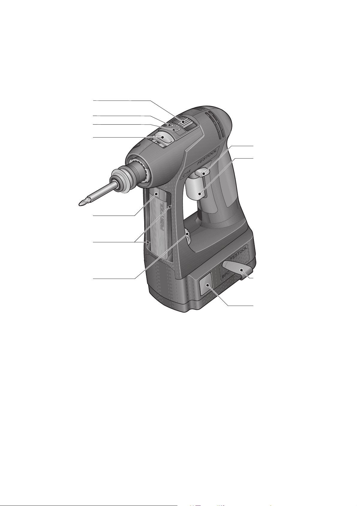
[1-1] Torque thumbwheel
[1-2] Bit store
[1-3] LED lamp
[1-4] Gear switch
Intended use
Cordless drills are suitable for drilling into
metal, wood, plastics and similar materials
as well as inserting and tightening screws.
The charger TRC 3 is design for charging the
battery packs listed.
[1-5] Drilling symbol
[1-6] Screwdriving symbol
[1-7] Drilling/Fastening selector switch
[1-8] Right/left switch
[1-9] On/Off switch
[1-10] Belt clip
[1-11] Buttons for releasing the battery
pack
WARNING
The user bears the responsibility for
damage and accidents caused by improper use; this also includes damage
and wear caused by continuous use in
industry.
9
Page 10
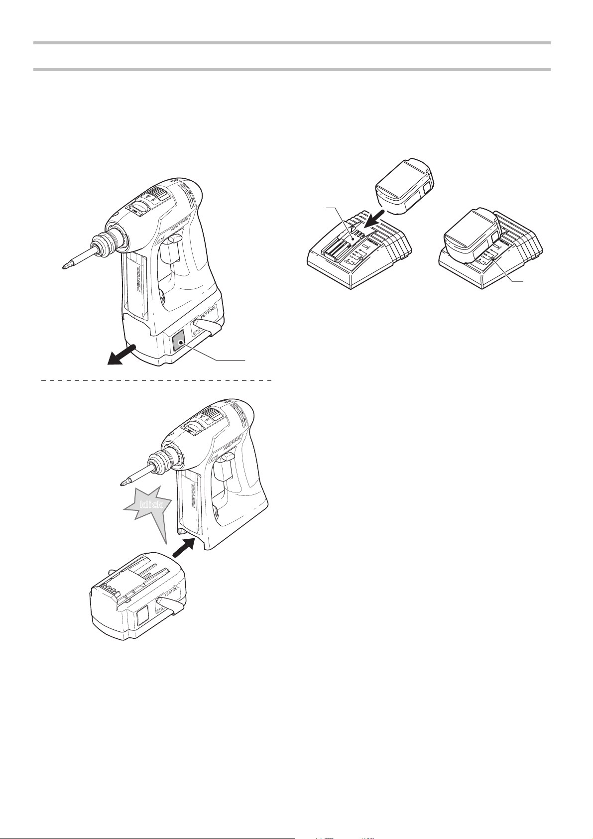
Changing the battery pack [2]
Removing the battery pack
X
Press and hold the two buttons [2-1].
X
Slide the battery pack forwards to remove.
remove
insert
Operation
X
X
3-1
The charger TRC 3 can be used to charge all
Festool battery packs of the BPS and BPC series. The charger automatically detects the
2-1
type of the inserted battery (NiCd, NiMH or
LiIon). A microprocessor controls the charging process in line with the charging state,
temperature and voltage of the battery pack.
The LED [3-2] on the charger indicates the
respective operating status of the charger.
To charge the battery pack, slide all the
way onto the retainer [3-1] on the charger.
To remove, slide off the charged battery
pack in similar fashion.
3-2
klick
2
Inserting the battery pack
X
Slide the battery pack onto the retainer
on the underside of the handle shown in
Fig. until it engages..
Charging the battery pack [3]
LED yellow - lit continuously
Charger is ready to use.
LED green - flashing quickly
Battery pack is charged to maximum capacity.
LED green - flashing slowly
Battery pack is charged with reduced current, LiIon is charged to 80 %.
LED green - lit continuously
Battery pack is fully charged, or charging is
not started again, because the battery is
charged to more than 80 %.
LED red - flashing
Battery temperature is outside the permitted
range.
LED red - lit continuously
General fault display, e.g. incomplete contact, short circuit, battery pack faulty, etc.
L
The battery pack is delivered partially
charged. Charge the battery pack completely before using for the first time.
10
Charger wall mounting TRC 3
There are two elongated holes on the back of
the TRC 3 for mounting the charger to a wall
Page 11
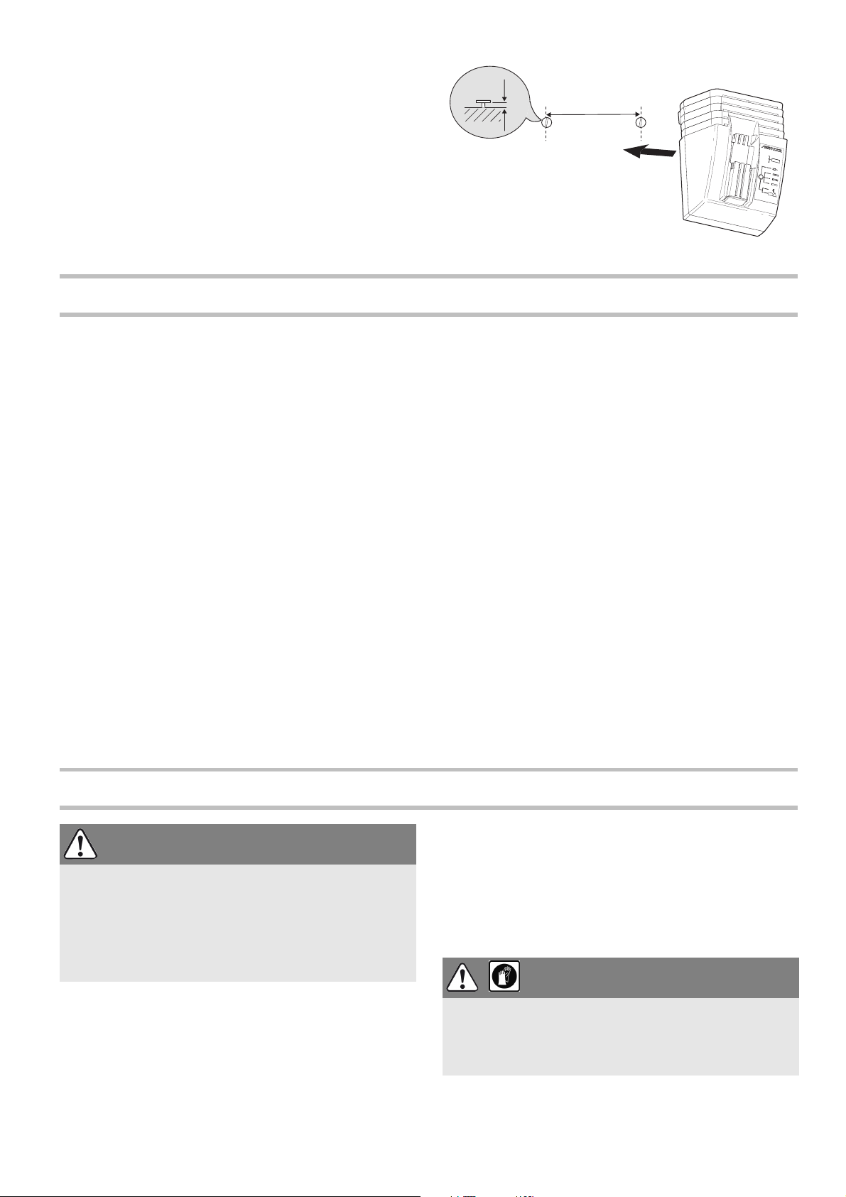
using two screws (e.g. round head or flat
4 mm/
0.16''
96 mm/
3.78 ''
head screw with shank diameter of 5 mm).
X
Insert the two screws into the wall at a
distance of 96 mm from one another and
leave the screw heads protruding approx.
4mm.
Settings
Consider the pictures on the fold-out page.
Changing the direction of rotation
The right/left switch [1-8] changes the direc-
tion of rotation.
• Move switch from right to left = clockwise
rotation
• Move switch from left to right = anticlockwise rotation
Changing gear
L
Always switch off the machine before
changing gear!
You can change gear using the gear switch
[1-4].
• Switch forwards (Number 1 visible) = first
gear
• Switch backwards (Number 2 visible) =
second gear
Fastening
Adjust the switch [1-7] so that its marking
faces the screw symbol [1-6]. The torque
can be adjusted in this position.
L
The switch-over function only works if the
machine is switched off.
X
Adjust the torque accordingly at the
torque wheel [1-1]:
Position 1 = low torque
Position 25 = high torque
The machine switches off when the preset
torque is reached and an acoustic signal
sounds. The machine only continues running
when the on/off switch [1-9] is released and
then pressed again.
Drilling
Adjust the switch [1-7] so that its marking
faces the drilling symbol [1-5]. Maximum
torque is set in this position.
Risk of injury
X
Make sure that the machine is switched off
and the battery pack has been removed
before changing the tool holding fixure,
attachments and tools.
WARNING
Tool holder, attachments
Tool chuck CENTROTEC WH-CE
The tool chuck CENTROTEC WH-CE allows
you to change tools with a CENTROTEC
shank in a matter of seconds.
L
Always use a CENTROTEC tool chuck to
clamp CENTROTEC tools.
Risk of cutting injuries when changing
the tool!
X
Wear protectiv gloves!
CAUTION
11
Page 12
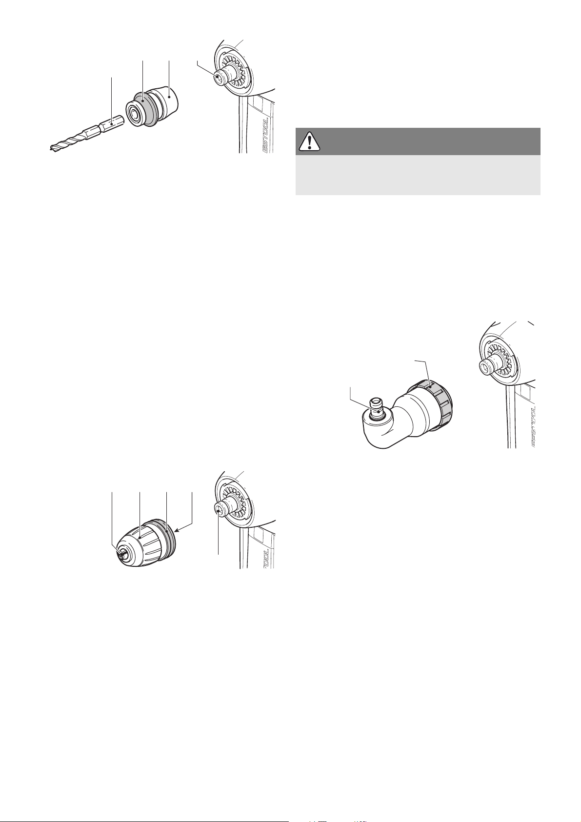
WH-CE
DD-AS
2-7
1-7
CENTROTEC
®
5-1
5-2 5-3 5-4
Changing tools
X
Turn the clamping sleeve [6-2] anticlockwise to open the clamping jaws [6-1].
L
The arrow on the spindle indicates the
opening direction.
X
Insert the tool into the chuck.
CAUTION
Attaching the CENTROTEC
X
Pull the release ring [5-3] forwards.
X
Attach the tool chuck to the drill spindle
[5-4].
X
Release the ring [5-3].
Detaching the CENTROTEC
X
Pull the release ring [5-3] forwards.
X
Remove the tool chuck.
Changing tools
X
Pull back the green release ring [5-2] to
attach or detach tools with a CENTROTEC
shank.
X
When attaching the tool, rotate until the
hexagon shank [5-1] engages in the
hexagon holder on the drill spindle.
X
Release the ring [5-2].
Chuck BF-FX
The chuck BF-FX is used for clamping drill
and screwdriver bits.
BF-FX
Attaching the chuck BF-FX
X
Attach the chuck to the drill spindle [6-5].
X
Pull the release ring [6-3] forwards.
X
Turn until the hexagon pin [6-4] on the
chuck engages in the hexagon socket
holder in the drill spindle.
X
Push the chuck all the way onto the drill
spindle.
X
Release the ring [6-4].
Detaching the chuck BF-FX
X
Pull the release ring [6-4] forwards.
X
Remove the chuck.
6-2
6-3 6-46-1
6-5
Risk of injury
X
Clamp the tool centrally in the chuck!
X
Turn the clamping sleeve [6-2] clockwise
to clamp the tool.
Angle attachment DD-AS
The angle attachment DD-AS (partly accessories) allows you to work (drill, fasten) vertically in relation to the longitudinal axis on
the machine.
Fitting the angle attachment DD-AS
X
Fit the angle attachment to the drill spindle.
X
Turn the attachment until is engages in
the required position.
L
You can engage the angle attachment in
16 different positions.
X
Turn the securing ring [7-2] firmly clockwise to lock the angle attachment.
Removing the angle attachment DD-AS
X
Turn the securing ring [7-2] anticlockwise
all the way.
X
Remove the angle attachment.
Attaching/Detaching the chuck
The chuck is secured to the shaft [7-1] of the
angle attachment and the drill spindle on the
machine in the same way.
Eccentric attachment DD-ES
The eccentric attachment (partly accessories) enables you to fasten close to abutting
12
Page 13
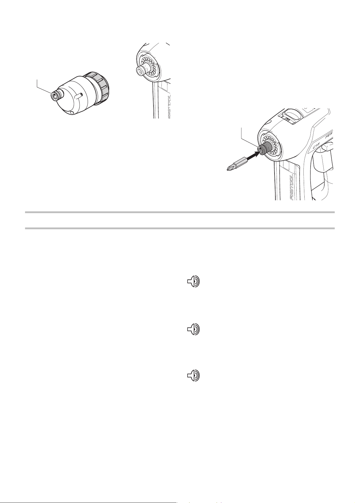
edges. The tool holder was designed for bits
9-1
in accordance with DIN 3126.
DD-ES
Attaching/Detaching the chuck
The chuck is secured to the shaft [8-1] of the
eccentric attachment and the drill spindle on
the machine in the same way.
Tool holder in the drill spindle
1-8
Attaching/Detaching eccentric attachment DD-ES
The eccentric attachment is attached/detached in the same way as the angle attachment (Section "Angle attachment DD-AS").
Working with the machine
Consider the pictures on the fold-out page.
Bits can be inserted directly in the hexagon
socket holder on the drill spindle [9-1] to
shorten and reduce the weight of the machine.
Acoustic warning signal
Switch on/off
The switch [1-9] is an on/off switch (press =
ON, release = OFF).
L
The speed of the machine depends on
how far the ON/OFF switch is pressed in.
L
When the ON/OFF switch is released, the
working spindle (chuck) stops immediately.
The LED lamp [1-3] lights up when the on/off
switch [1-9] is pressed and lights up the
working area.
Bit store
Bits or bit holders are inserted sideways into
the bit store [1-2].
Acoustic warning signals sound and the machine switches off in the following operating
states:
peep ― ―
– Battery flat or machine overloaded.
X
Change the battery.
X
Place the machine under reduced stress.
peep peep ―
– Machine is overheating.
X
You must allow the machine to cool before
using again.
peep peep peep
– LiIon battery pack is faulty or has over-
heated.
X
Once the battery pack has cooled, perform a functional check using the charger.
13
Page 14
Service and maintenance
10-1
10-2
10-3
WARNING
Any maintenance or repair work that
requires opening of the motor or gear
housing should only be carried out by
an authorised Customer Service Centre
(name supplied by your dealer)!
X
Maintenance or repair work carried out by
an unauthorised person can lead to the
wrong connection of the power leads or
other components, which in turn can lead
to accidents with serious consequences.
Observe the following instructions:
– Keep the air slits on the machine and the
charger free and clean to ensure adequate
cooling.
– Keep the contacts on the machine, charger
and battery pack clean.
Information on battery packs
– Where possible, store the battery pack in a
cool, dry place at a temperature between
5°C and 25 °C.
– Battery packs are most efficient at temper-
atures between 20 °C and 30 °C.
– Protect the battery pack from moisture,
water and heat.
– Significantly shorter operating times after
each charge indicate that the battery pack
is worn and should be replaced with a new
one.
– The LiIon battery pack is fully compatible
with the charger! Integrated electronics
prevent overloading and overheating during the charging process.
– Do not leave flat battery packs in a charger
disconnected from the mains power supply
for longer than one month. There is a risk
of total discharge and the maximum power
of the battery pack may decrease.
– Store the battery pack in its packaging to
reduce the risk of short circuits..
– If LiIon battery packs are to be stored for
long periods without use, they should be
charged to 40 % capacity (approx.
15 mins. charging period).
Accessories
Use only original Festool accessories and
Festool consumable material intended for
this machine because these components are
designed specifically for the machine. Using
accessories and consumable material from
other suppliers will most likely affect the
quality of your working results and limit any
warranty claims. Machine wear or your own
personal workload may increase depending
on the application. Protect yourself and your
machine, and preserve your warranty claims
by always using original Festool accessories
and Festool consumable material!
The accessory and tool order number can be
found in yout festool catalog or on the Internet at „www.festool-usa.com“.
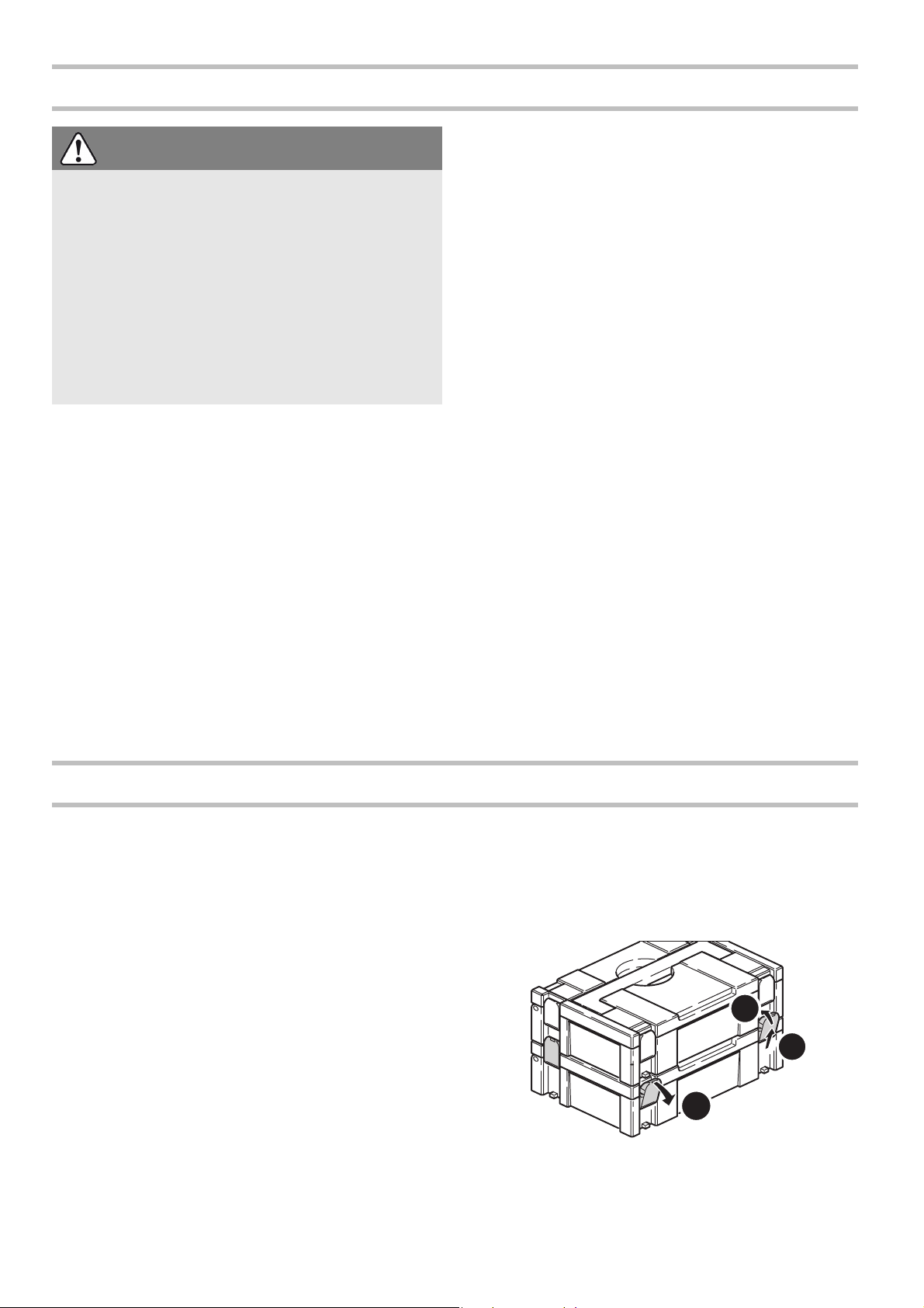
Systainer
Many Festool products are shipped in a
unique system container, called "Systainer".
This provides protection and storage for the
tool and accessories. The Systainers are
stackable and can be interlocked together.
They also can be interlocked atop Festool CT
dust extractors.
X
Place one systainer on top of the other.
X
Release all four latches on the lower systainer by pulling back at their top edges
[10-1].
14
Page 15

X
Slide all four latches upward [10-2].
X
Snap all four latches back to their flat position [10-3] so they engage the stacking
tabs of the upper systainer.
Disposal
Do not throw the power tool in your
household waste!!
Dispose of machines,
accessories and packaging at an environ-
Transport
The equivalent amount of lithium in the LiIon
battery pack is less than the applicable limit
value and certifi ed as per UN manual ST/SG/
AC.10/11/rev. 3 part III, subsection 38.3.
The LiIon battery pack is therefore not subject to national and international dangerous
Warranty
Conditions of 1+2 Warranty
You are entitled to a free extended warranty
(1 year + 2 years = 3 years) for your Festool
power tool. Festool shall be responsible for
all shipping costs during the first year of the
warranty. During the second and third year
of the warranty the customer is responsible
for shipping the tool to Festool. Festool will
pay for return shipping to the customer using
UPS Ground Service. All warranty service is
valid 3 years from the date of purchase on
your receipt or invoice.
Festool Limited Warranty
This warranty is valid on the pre-condition
that the tool is used and operated in compliance with the Festool operating instructions.
Festool warrants, only to the original consumer purchaser, that the specified tool will
be free from defects in materials and workmanship for a term of one year from the date
of procurement. Festool makes no other warranty, express or implied, for Festool portable power tools. No agent, representative,
distributor, dealer or employee of Festool has
the authority to increase or otherwise
change the obligations or limitations of this
warranty. The obligations of Festool in its
sole discretion under this warranty shall be
limited to the repair or replacement of any
mentally responsible recycling centre. Observe the valid national regulations.
goods regulations, neither as an individual
component nor as a fitted machine component. However, dangerous goods regulations
may apply when several battery packs are
transported, in which case you may have to
fulfil special conditions
Festool portable power tool that is found to
be defective as packaged with the User Manual.
Excluded from coverage under this warranty
are: normal wear and tear; damages caused
by misuse, abuse or neglect; damage caused
by anything other than defects in material
and workmanship. This warranty does not
apply to accessory items such as circular saw
blades, drill bits, router bits, jigsaw blades,
sanding belts, and grinding wheels. Also excluded are “wearing parts”, such as carbon
brushes, lamellas of air tools, rubber collars
and seals, sanding discs and pads, and batteries.
Festool portable power tools requiring replacement or repair are to be returned with
the receipt of purchase to Festool (call 800554-8741 for address details).
IN NO EVENT SHALL FESTOOL BE LIABLE FOR ANY CONSEQUENTIAL OR INCIDENTAL DAMAGES FOR BREACH OF
THIS OR ANY OTHER WARRANTY, EXPRESSED OR IMPLIED WHATSOEVER.
ALL WARRANTIES IMPLIED BY STATE
LAW, INCLUDING THE IMPLIED WARRANTIES OF MERCHANTABILITY AND
FITNESS FOR A PARTICULAR PURPOSE,
15
Page 16

ARE HEREBY LIMITED TO THE DURATION OF THREE YEARS.
Some states in the U.S. and some Canadian
provinces do not allow the limitations on how
long an implied warranty lasts, so the above
limitation may not apply to you. With the exception of any warranties implied by state or
province law as hereby limited, the foregoing
express limited warranty is exclusive and in
lieu of all other warranties, guarantees,
agreements and similar obligations of Festool.
This warranty gives you specific legal rights
and you may also have other rights which
vary from state to state in the U.S. and province to province in Canada.
16
Page 17

Sommaire
Symboles ................................ 17
Symboles
Consignes de sécurité ............... 17
Caractéristiques techniques........ 20
Description functionnelle............ 21
Utilisation en conformité avec les ins-
tructions.................................. 21
Mise en service ........................ 22
Réglages ................................. 23
Porte-outil, embouts ................. 23
Travail avec la machine ............. 25
Entretien et maintenance........... 26
Accessoires.............................. 27
Recyclage................................ 27
Transport................................. 27
Garantie.................................. 27
VVolt
AAmpère
Hz Hertz
~Tension alternative
n
tr/
min
Vitesse de rotation à vide
0
Classe II conception
tours ou course par minute
Diamètre
Information, astuce
Avertissement de danger général
Risque d'électrocution
Lire les instructions / les remarques !
Port d'une protection acoustique !
Consignes de sécurité
Consignes de sécurité d'ordre gé-
néral
ATTENTION ! Lire toutes les consignes de sécurité et indications.
non-respect des avertissements et instructions indiqués ci-après peut entraîner un
choc électrique, un incendie et/ou de graves
blessures.
Conserver tous les avertissements et
toutes les instructions pour pouvoir s'y
reporter ultérieurement.
Le terme " outil " dans les avertissements fait
reference à votre outil électrique alimenté
par le secteur (avec cordon d'alimentation)
ou votre outil fonctionnant sur batterie (sans
cordon d'alimentation).
1 PLACE DE TRAVAIL
a)
Maintenez l'endroit de travail propre
et bien éclairé.
sordre ou mal éclairé augmente le risque
d'accidents.
N'utilisez pas l'appareil dans un envi-
b)
ronnement présentant des risques
Un lieu de travail en dé-
Le
Porter des gants de protection !
d'explosion et où se trouvent des liquides, des gaz ou poussières inflammables.
génèrent des étincelles risquant d'enflammer les poussières ou les vapeurs.
Tenez les enfants et autres personnes
c)
éloignés durant l'utilisation de l'outil
électroportatif.
risquez de perdre le contrôle sur l'appareil.
2 SECURITE RELATIVE AU SYSTEME
ELECTRIQUE
a)
La fiche de secteur de l'outil électroportatif doit être appropriée à la prise
de courant. Ne modifiez en aucun cas
la fiche. N'utilisez pas de fiches
d'adaptateur avec des appareils avec
mise à la terre.
et les prises de courant appropriées réduisent le risque de choc électrique.
Evitez le contact physique avec des
b)
surfaces mises à la terre tels que
tuyaux, radiateurs, fours et réfrigérateurs.
Les outils électroportatifs
En cas d'inattention vous
Les fiches non modifiées
Il y a un risque élevé de choc élec-
17
Page 18

trique au cas où votre corps serait relié à la
terre.
N'exposez pas l'outil électroportatif à
c)
la pluie ou à l'humidité.
La pénétration
d'eau dans un outil électroportatif augmente le risque d'un choc électrique.
N'utilisez pas le câble à d'autres fins
d)
que celles prévues, n'utilisez pas le
câble pour porter l'appareil ou pour
l'accrocher ou encore pour le débrancher de la prise de courant. Maintenez
le câble éloigné des sources de chaleur, des parties grasses, des bords
tranchants ou des parties de l'appareil
en rotation.
Un câble endommagé ou torsadé augmente le risque d'un choc électrique.
Au cas où vous utiliseriez l'outil élec-
e)
troportatif à l'extérieur, utilisez une
rallonge autorisée homologuée pour
les applications extérieures.
L'utilisation d'une rallonge électrique homologuée
pour les applications extérieures réduit le
risque d'un choc électrique.
Si l'usage d'un outil dans un emplace-
f)
ment humide est inévitable, utiliser
une alimentation protégée par un dispositif à courant différentiel résiduel
(RCD).
L'usage d'un RCD réduit le risque
de choc électrique.
avant de retirer la fiche de la prise de
courant.
Le fait de porter l'appareil avec le
doigt sur l'interrupteur ou de brancher
l'appareil sur la source de courant lorsque
l'interrupteur est en position de fonctionnement, peut entraîner des accidents.
Enlevez tout outil de réglage ou toute
d)
clé avant de mettre l'appareil en fonctionnement.
Une clé ou un outil se trouvant sur une partie en rotation peut causer
des blessures.
Ne surestimez pas vos capacités.
e)
Veillez à garder toujours une position
stable et équilibrée.
Ceci vous permet de
mieux contrôler l'appareil dans des situations inattendues.
Portez des vêtements appropriés. Ne
f)
portez pas de vêtements amples, ni de
bijoux. Gardez les cheveux et les vêtements à distance des pièces mobiles.
Des vêtements amples, des bijoux ou des
cheveux longs peuvent être happés par les
pièces en mouvement.
Si des dispositifs servant à aspirer ou
g)
à recueillir les poussières doivent être
utilisés, vérifiez que ceux-ci soient effectivement raccordés et qu'ils sont
correctement utilisés.
L'utilisation de
tels dispositifs réduit les dangers dus aux
poussières.
3 SECURITE DES PERSONNES
a)
Restez vigilant, surveillez ce que vous
faites. Faites preuve de bon en utilisant l'outil électroportatif. N'utilisez
pas l'appareil lorsque vous êtes fatigué ou après avoir consommé de l'alcool, des drogues ou avoir pris des
médicaments.
Un moment d'inattention
lors de l'utilisation de l'appareil peut entraîner de graves blessures sur les personnes.
Portez des équipements de protec-
b)
tion. Portez toujours des lunettes de
protection.
Le fait de porter des équipements de protection personnels tels que
masque anti-poussières, chaussures de
sécurité antidérapantes, casque de protection ou protection acoustique suivant le
travail à effectuer, réduit le risque de blessures.
Evitez une mise en service par mégar-
c)
de. Assurez-vous que l'interrupteur
est effectivement en position d'arrêt
4 UTILISATION ET EMPLOI SOIGNEUX
DE L'OUTIL ELECTROPORTATIF
a)
Ne surchargez pas l'appareil. Utilisez
l'outil électroportatif approprié au travail à effectuer.
Avec l'outil électroportatif approprié, vous travaillerez mieux et
avec plus de sécurité à la vitesse pour laquelle il est prévu.
N'utilisez pas un outil électroportatif
b)
dont l'interrupteur est défectueux.
Un
outil électroportatif qui ne peut plus être
mis en ou hors fonctionnement est dangereux et doit être réparé.
Retirer la fiche de la prise de courant
c)
avant d'effectuer des réglages sur
l'appareil, de changer les accessoires,
ou de ranger l'appareil.
Cette mesure de
précaution empêche une mise en fonctionnement par mégarde.
Gardez les outils électroportatifs non
d)
utilisés hors de portée des enfants. Ne
permettez pas l'utilisation de l'appareil à des personnes qui ne se sont pas
18
Page 19

familiarisées avec celui-ci ou qui n'ont
pas lu ces instructions.
troportatifs sont dangereux lorsqu'ils sont
utilisés par des personnes non initiées.
Prenez soin des outils électroporta-
e)
tifs. Vérifiez que les parties en mouvement fonctionnent correctement et
qu'elles ne soient pas coincées, et
contrôlez si des parties sont cassées
ou endommagées de telle sorte que le
bon fonctionnement de l'appareil s'en
trouve entravé. Faites réparer les parties endommagées avant d'utiliser
l'appareil.
dus à des outils électroportatifs mal entretenus.
Maintenez les outils de coupe aiguisés
f)
et propres.
tretenus avec des bords tranchants bien
aiguisés se coincent moins souvent et peuvent être guidés plus facilement.
Utilisez les outils électroportatifs, les
g)
accessoires, les outils à monter etc.
conformément à ces instructions et
aux prescriptions en vigueur pour ce
type d'appareil. Tenez compte également des conditions de travail et du
travail à effectuer.
électroportatifs à d'autres fins que celles
prévues peut entraîner des situations dangereuses.
5 UTILISATION ET EMPLOI SOIGNEUX
DES APPAREILS SANS FIL
a)
Ne chargez les accumulateurs que
dans des chargeurs recommandés par
le fabricant.
type spécifique d'accumulateur peut engendrer un risque d'incendie lorsqu'il est
utilisé avec d'autres accumulateurs.
Dans les outils électroportatifs, n'uti-
b)
lisez que les accumulateurs spécialement prévus pour celui-ci.
de tout autre accumulateur peut entraîner
des blessures et des risques d'incendie.
Tenez l'accumulateur non-utilisé à
c)
l'écart de toutes sortes d'objets métalliques tels qu'agrafes, pièces de
monnaie, clés, clous, vis ou autres,
étant donné qu'un pontage peut provoquer un court-circuit.
De nombreux accidents sont
Des outils soigneusement en-
L'utilisation des outils
Un chargeur approprié à un
Les outils élec-
L'utilisation
Un court-circuit
entre les contacts d'accu peut provoquer
des brûlures ou un incendie.
En cas d'utilisation abusive, du liquide
d)
peut sortir de l'accumulateur. Evitez
tout contact avec ce liquide. En cas de
contact par mégarde, rincez soigneusement avec de l'eau. Au cas où le liquide rentrerait dans les yeux,
consultez en plus un médecin.
de qui sort de l'accumulateur peut entraîner des irritations de la peau ou causer des
brûlures.
6 SERVICE
a)
Ne faites réparer votre outil électroportatif que par un personnel qualifié
et seulement avec des pièces de rechange d'origine.
la sécurité de l'appareil.
Ceci permet d'assurer
Le liqui-
Consignes de sécurité spécifiques
à la machine
–
Portez une protection acoustique lors
de l'utilisation de perceuses à percussion.
pertes auditives.
Utilisez les poignées additionnelles
–
fournies avec l'outil électrique.
du contrôle de l'outil électrique peut entraîner des blessures.
Tenez l'appareil uniquement au ni-
–
veau des surfaces isolées de la poignée lorsque vous effectuez des
travaux au cours desquels la vis risque
de toucher des câbles électriques cachés.
sous tension peut également mettre des
pièces métalliques de l'appareil sous tension et provoquer un choc électrique.
L'effet du bruit peut occasionner des
perte
Le contact de la vis avec un câble
La poussière, un risque
pour la santé
AVERTISSEMENT!
res créées par le ponçage mécanique,
le sciage, le meulage, le perçage et
autres activités reliées à la construction contiennent des substances chimiques connues
(dans l’État de la Californie) comme pouvant
causer le cancer, des anomalies congénitales
ou représenter d’autres dangers pour la reproduction. Voici quelques exemples de telles substances:
Certaines poussiè-
19
Page 20

• plomb provenant de peintures à base de
plomb,
• silice cristallisée utilisée dans les briques,
le ciment et autres matériaux de maçonnerie, et
• arsenic et chrome du bois d’oeuvre traité
avec un produit chimique.
d’exposition à ces substances chimiques :
travaillez dans un endroit adéquatement
ventilé et utilisez un équipement de sécurité
approuvé, tel que masques antipoussières
spécialement conçus pour filtrer les particules microscopiques.
AVERTISSEMENT
Le risque d’exposition à de
tels produits varie selon la
fréquence à laquelle vous
faites ce genre de travail.
Pour réduire les risques
POUR RÉDUIRE LE RISQUE DE DOMMAGES, L'UTILISATEUR DOIT LIRE LE MANUEL D'INSTRUCTION.
Caractéristiques techniques
Perceuses-visseuses sans fil C12 Li C15 Li
Tension du moteur 10,8 - 12 V 14,4 - 15,6 V
Vitesse à vide * 1ère vitesse 0 - 450 tr/mn
2ème vitesse 0 - 1500 tr/min
Couple max. Cas de vissage "doux"
(bois)
Cas de vissage "dur"
(métal)
Couple réglable ** 1ère vitesse 0,5 - 8 Nm
2ème vitesse 0,5 - 6 Nm
Mandrin de perçage, plage de serrage 1,5 - 13 mm
Diamètre de perçage max. Bois 25 mm 35 mm
Métal 14 mm 16 mm
Porte-outil dans la broche de perçage 1/4 ’’ 1/4 ’’
Poids sans batterie, avec mandrin Centrotec 0,9 kg 1,0 kg
Chargeur TRC 3
Tension de réseau (entrée) 120 V ~
Fréquence du réseau 60 Hz
Tension de charge (sortie) 7.2 - 18 V (DC)
Charge rapide max. 3 A
20 Nm 25 Nm
34 Nm 40 Nm
Charge de maintien, pulsée env. 0.06 A
Temps de charge pour LiIon 1.3 Ah/ 2.6 Ah, 80 % env. 22/ 45 minutes
LiIon 1.3 Ah/ 2.6 Ah, 100 % env. 35/ 70 minutes
Plage de température de charge admissible -5 °C a +45 °C
Surveillance de la température au moyen d’une résistance
CTN
20
Page 21

Batterie BPC 12 Li BPC 15 Li
Référence 497019 497020
Tensi on 10,8 V 14,4 V
Capacité 1,3 Ah 2,6 Ah
Poids 0,3 kg 0,6 kg
* Indications de vitesse de rotation avec batterie entièrement chargée.
** La vitesse de rotation maximale est réduite dans les plages de couple inférieures.
Description functionnelle
Des eléments fournis sont disponibles sur le
volet qui se trouve au début de cette notice
d'utilisation. Vous pouvez ainsi déplier cette
page et visualiser en permanence les différentes parties de l'outil lorsque vous lisez la
notice.
[1-1] Molette de réglage du couple
[1-2] Support d’embouts
[1-3] Lampe à LED
[1-4] Commutateur de vitesses
Utilisation en conformité avec les instructions
Les perceuses-visseuses sans fi l sont appropriées pour le perçage dans le métal, le bois,
les matières plastiques et autres matériaux
similaires, ainsi que pour le vissage et le serrage de vis.
Le chargeur TRC 3 est conçu pour la charge
des batteries indiquées.
[1-5] Symbole de perçage
[1-6] Symbole de vissage
[1-7] Commutateur perçage / vissage
[1-8] Commutateur pour rotation à droite
/ rotation à gauche
[1-9] Interrupteur de marche/arrêt
[1-10] Clip-ceinture
[1-11] Touches pour desserrer l’accumula-
teur
AVERTISSEMENT
L'utilisateur est responsable des dommages et accidents provoqués par une
utilisation non conforme; cela concerne
également les endommagements et
usures du fait d’un fonctionnement industriel continu.
21
Page 22

Mise en service
Remplacement de la batterie [2]
Retirer la batterie
X
Pressez les deux touches [2-1].
X
Retirez la batterie par l'avant.
retirer
2-1
insérer
X
Insérez la batterie à charger jusqu'en butée, dans le logement [3-1] du chargeur.
X
Vous pouvez retirer la batterie chargée
dans le sens inverse.
3-1
3-2
Le chargeur TRC 3 permet de charger toutes
les batteries Festool des séries BPS et BPC.
Le chargeur reconnaît automatiquement le
type de batterie inséré (NiCd, NiMH ou Liion). Un microprocesseur pilote le processus
de charge, en fonction de l'état de charge, de
la température et de la tension de la batterie.
La LED [3-2] du chargeur indique l'état de
service respectif du chargeur.
klick
2
Insérer la batterie
X
Insérez la batterie jusqu'à l'enclenchement dans le logement sur la partie inférieure de la poignée, comme indiqué sur
la figure.
Charge de la batterie [3]
LED jaune - allumée en continu
Le chargeur est opérationnel.
LED verte - clignotement rapide
La batterie est chargée avec le courant maximal.
LED verte - clignotement lent
La batterie est chargée avec un courant réduit, la batterie Li-ion est chargée à 80 %.
LED verte - allumée en continu
Le processus de charge est terminé ou n'est
pas redémarré, étant donné que l'état de
charge actuel est supérieur à 80 %.
LED rouge - clignotement
La température de la batterie est en-dehors
des valeurs limites admissibles.
LED rouge - allumée en continu
Affichage de défaut général, p. ex. pas de
contact total, court-circuit, batterie défectueuse, etc.
L
La batterie est livrée partiellement chargée. Avant la première utilisation, chargez
entièrement la batterie.
22
Fixation murale du chargeur TRC 3
Le chargeur TRC 3 est pourvu sur sa face arrière de deux trous oblongs. Il peut être fixé
à un mur au moyen de deux vis (p. ex. vis à
Page 23

tête demi-ronde ou vis à tête plate, avec un
4 mm/
0.16''
96 mm/
3.78 ''
diamètre de tige de 5 mm).
X
Vissez les deux vis dans le mur à une distance de 96 mm, de manière à ce que les
têtes de vis se trouvent encore à env.
4mm du mur.
Réglages
Attention aux illustrations au début de la présente notice d’utilisation.
Commutation du sens de rotation
Le commutateur gauche - droite [1-8] vous
permet de définir le sens de rotation.
• Commutateur de la droite vers la gauche
= rotation à droite
• Commutateur de la gauche vers la droite
= rotation à gauche.
Commutation du réducteur
L
Actionner la commutation du réducteur
uniquement lorsque l'appareil est à l'arrêt.
Le commutateur de vitesses [1-4] vous permet de commuter le réducteur.
• Commutateur vers l'avant (chiffre 1 visible) = 1ère vitesse
• Commutateur vers l'arrière (chiffre 2 visible) = 2ème vitesse
Vissage
Réglez le commutateur inverseur [1-7] de
manière à ce que son repère soit pointé sur
le symbole de vissage [1-6]. Le couple peut
être réglé dans cette position.
L
La commutation fonctionne uniquement
lorsque la machine est arrêtée.
X
Réglez le couple via la molette de réglage
du couple [1-1] :
Position 1 = petit couple,
Position 25 = grand couple
La machine s'arrête en atteignant le couple
réglé et un signal sonore indique l'atteinte de
la valeur de désactivation. La machine redémarre seulement après avoir relâché et pressé à nouveau l'interrupteur de marche/arrêt
[1-9].
Perçage
Réglez le commutateur inverseur [1-7] de
manière à ce que son repère soit pointé sur
le symbole de perçage [1-5]. Le couple maximal est réglé dans cette position.
Risque de blessures
X
A chaque remplacement du porte-outil, du
groupe d’appui et de l’outil, assurez-vous
que la machine est convenablement inactivée et que l’accumulateur est enlevé..
Porte-outil, embouts
AVERTISSEMENT
Mandrin CENTROTEC WH-CE
Le mandrin CENTROTEC WH-CE permet un
remplacement rapide des outils avec tige
CENTROTEC.
L
Montez uniquement les outils CENTROTEC
dans le mandrin CENTROTEC.
23
Page 24

ATTENTION
DD-AS
2-7
1-7
Lors du remplacement d'outil, l'outil
peut occasionner des blessures par
coupure !
X
Portez des gants de protection !
WH-CE
CENTROTEC
®
5-2 5-3 5-4
5-1
Montage du mandrin CENTROTEC
X
Tirez la bague de déverrouillage [5-3]
vers l'avanct.
X
Montez le mandrin jusqu'en butée sur la
broche de la perceuse [5-4].
X
Relâchez la bague de déverrouillage [5-
3].
Démontage du mandrin CENTROTEC
X
Tirez la bague de déverrouillage [5-3]
vers l'avant.
X
Retirez le mandrin.
Remplacement d'outil
X
Pour monter ou démonter un outil avec
tige CENTROTEC, tirez la bague de déverrouillage verte [5-2] en arrière.
X
Lors du montage, tournez l'outil jusqu'à
ce que sa tige à six pans [5-1] s'engage
dans le logement six pans de la broche de
la perceuse.
X
Relâchez la bague de déverrouillage [5-
2].
Mandrin de perçage BF-FX
Le mandrin de perçage BF-FX sert au serrage
de forets et d'embouts.
Montage du mandrin de perçage BF-FX
X
Montez le mandrin de perçage sur la broche de la perceuse [6-5].
X
Tirez la bague de déverrouillage [6-3]
vers l'avant.
X
Tournez-la jusqu'à ce que la broche carrée
[6-4] du mandrin de perçage s'engage
dans le logement six pans creux de la broche de la perceuse.
X
Pressez le mandrin de perçage jusqu'en
butée sur la broche de la perceuse.
X
Relâchez la bague de déverrouillage [6-
4].
Démontage du mandrin de perçage BFFX
X
Tirez la bague de déverrouillage [6-4]
vers l'avant.
X
Retirez le mandrin de perçage.
Remplacement d'outil
X
Tournez la douille de serrage [6-2] dans
le sens inverse des aiguilles d'une montre,
afin d'ouvrir les mâchoires de serrage [6-
1].
L
La flèche se trouvant sur la broche indique
le sens de rotation pour l'ouverture.
X
Montez l'outil dans le mandrin de perçage.
ATTENTION
Risques de blessures
X
Serrez l'outil de façon centrée dans le
mandrin !
X
Tournez la douille de serrage [6-2] dans le
sens des aiguilles d'une montre, afin de
serrer l'outil.
Renvoi d'angle DD-AS
Le renvoi d'angle DD-AS (certaines sont des
accessoires) permet de travailler (percer,
visser) perpendiculairement par rapport à
l'axe longitudinal de la machine.
24
BF-FX
6-2
6-3 6-46-1
6-5
Page 25

Montage du renvoi d'angle DD-AS
9-1
X
Montez le renvoi d'angle sur la broche de
la perceuse.
X
Tournez-le jusqu'à ce qu'il s'engage dans
la position souhaitée.
L
Le renvoi d'angle peut être fixé dans 16
positions angulaires différentes.
X
Tournez la bague de fixation [7-2] dans le
sens des aiguilles d'une montre, afin de
verrouiller le renvoi d'angle.
Démontage du renvoi d'angle DD-AS
X
Tournez la bague de fixation [7-2] dans le
sens inverse des aiguilles d'une montre,
jusqu'en butée.
X
Retirez le renvoi d'angle.
Montage / démontage du mandrin de
perçage
Le mandrin de perçage est fixé sur l'arbre [7-
1] du renvoi d'angle de la même manière que
sur le broche de la perceuse.
Montage / démontage du module excentrique DD-ES
Le montage / démontage du module excentrique s'effectue de manière analogue au
montage / démontage du renvoi d'angle
(chapitre "Renvoi d'angle DD-AS").
Montage / démontage du mandrin de
perçage
Le mandrin de perçage est fixé sur l'arbre [8-
1] du module excentrique de la même ma-
nière que sur le broche de la perceuse.
Porte-outil dans la broche de la
perceuse
Afin d'alléger et de raccourcir la longueur de
la machine, les embouts peuvent être montés directement dans le logement six pans
creux de la broche de la perceuse [9-1].
Module excentrique DD-ES
Le module excentrique DD-ES (certaines
sont des accessoires) permet un vissage au
ras des bords. Le porte-outil est conçu pour
des embouts selon DIN 3126.
DD-ES
1-8
Travail avec la machine
Attention aux illustrations au début de la présente notice d’utilisation.
Marche/Arrêt
L'interrupteur [1-9] fait office d'interrupteur
de marche/arrêt (pression = MARCHE, relâchement = ARRET).
L
La vitesse de rotation est réglable en
fonction de la pression sur l'interrupteur
MARCHE / ARRET.
L
Après avoir relâché l'interrupteur MARCHE / ARRET, la broche (mandrin de perçage) est freinée, ce qui empêche une
marche par inertie de l'outil.
La lampe à LED [1-3] est allumée lorsque
l'interrupteur de marche/arrêt [1-9] est
pressé et éclaire la zone de travail.
Support d'embouts
Des embouts ou des porte-embouts peuvent
être insérés latéralement dans le support
d'embouts [1-2].
25
Page 26

Signaux d'avertissement sonores
Des signaux d'avertissement sonores retentissent lors des états de fonctionnement suivants et la machine s'arrête :
peep ― ―
– Batterie déchargée ou machine surchar-
gée.
X
Remplacez la batterie.
X
Réduisez la charge de la machine.
Entretien et maintenance
AVERTISSEMENT
Tout travail de maintenance ou de réparation, qui nécessite l'ouverture du moteur ou du carter d'engrenages doit
uniquement être effectué par un centre
service-client autorisé (nom fourni par
votre revendeur) !
X
Les travaux de maintenance ou de réparation effectués par un personnel non autorisé peuvent conduire à la mauvaise
connexion de câbles d'alimentation ou
d'autres composants, ce qui peut entraîner à son tour des accidents avec des conséquences graves.
Observez les consignes suivantes :
– Maintenez les ouvertures d'aération sur la
machine électrique et sur le chargeur dans
un état propre, afin de garantir le refroidissement.
– Maintenez les contacts de raccordement
sur la machine électrique, le chargeur et la
batterie dans un état propre.
Remarques concernant les batteries
– Stockez de préférence les batteries dans
un endroit sec et frais, dans une plage de
température comprise entre 5 °C et
25 °C.
– La capacité de rendement optimale des
batteries est obtenue dans une plage de
peep peep ―
– La machine est surchauffée.
X
Après refroidissement, vous pouvez remettre la machine en marche.
peep peep peep
– La batterie Li-ion est surchauffée ou défec-
tueuse.
X
Contrôlez sa capacité de fonctionnement
avec le chargeur, avec la batterie refroidie.
température comprise entre 20 °C et
30 °C.
– Protégez les batteries contre l'humidité et
l'eau, ainsi que contre la chaleur.
– Une durée d'utilisation nettement raccour-
cie après chaque charge indique que la
batterie est usagée et qu'elle doit être
remplacée par une batterie neuve.
– La batterie Li-ion et le chargeur sont par-
faitement adaptés l'un à l'autre ! Une électronique intégrée empêche une surcharge
dommageable ou une surchauffe lors du
processus de charge.
–Du fait de la conservation de la batterie
dans le chargeur opérationnel, la batterie
est maintenue en permanence à l'état
chargé par maintien continu de la charge.
– Ne laissez pas les batteries déchargées
pendant plus d'environ un mois dans le
chargeur, si le chargeur est débranché du
réseau. Il y a risque de décharge profonde
et par conséquent de limitation de la capacité de l'accumulateur.
– L'accumulateur devrait être conservé dans
son emballage d'origine, afin d'exclure tout
risque de court-circuits.
– Si des batteries Li-ion devaient être stoc-
kées sans utilisation pendant une période
prolongée, elles devraient être chargées à
40 % de la capacité (durée de charge env.
15 minutes).
26
Page 27

Accessoires
10-1
10-2
10-3
Utilisez uniquement les accessoires Festool
et consommables Festool d'origine prévus
pour cette machine, car ces composants systèmes sont parfaitement adaptés les uns par
rapport aux autres. Si vous utilisez des accessoires et consommables d'autres marques, la qualité du résultat peut être dégradée et les recours en garantie peuvent être
soumis à des restrictions. L'usure de la machine ou votre charge personnelle peuvent
augmenter selon chaque application. Pour
cette raison, protégez-vous, votre machine
et vos droits à la garantie en utilisant exclusivement des accessoires Festool et des
consommables Festool d'origine !
Les références des accessoires et des outils
figurent dans le catalogue Festool ou sur Internet sous „www.festool-usa.com“.
Systainer
De nombreux produits Festool sont fournis
dans une caisse exclusive, appelée "Systainer". Celle-ci permet de protéger et de ranger des outils et des appareils complémentaires. Les Systainer sont empilables et peu-
vent être solidarisés. En outre, il se fixent sur
les aspirateurs CT Festool.
X
Poser deux Systainer l'un sur l'autre.
X
Défaire les quatre éléments de verrouillage du Systainer inférieur en les tirant en
arrière par leur bord supérieur [10-1].
X
Pousser les quatre éléments de verrouillage vers le haut [10-2].
X
Manoeuvrer les quatre éléments de verrouillage [10-3] de sorte qu'ils s'enclenchent au niveau des éléments récepteurs
du Systainer supérieur..
Recyclage
Ne jetez pas les outils électriques avec
les ordures ménagères!
Eliminez les appa-
reils, les accessoires et les emballages de fa-
Transport
La quantité équivalente de lithium contenue
dans la batterie Li-ion se situe sous les valeurs limites applicables et est contrôlée
d'après le manuel UN ST/SG/AC.10/11/Rev.3
partie III, sous-paragraphe 38.3. Pour cette
raison, la batterie Li-ion n'est soumise, ni en
tant que composant individuel, ni insérée
dans un appareil, aux prescriptions nationa-
Garantie
çon compatible avec l'environnement. Respectez en cela les dispositions nationales en
vigueur .
les et internationales concernant les matières dangereuses. Les prescriptions concernant les matières dangereuses peuvent toutefois être applicables en cas de transport de
plusieurs batteries. Dans ce cas il peut s'avérer nécessaire de respecter des conditions
particulières.
Conditions de la garantie (1+2 ans)
Vous avez droit à une prolongation de garantie gratuite (1 an + 2 ans = 3 ans) sur votre
outil électrique Festool. Festool assumera
tous les coûts d’expédition pendant la première année de la garantie alors que les
deuxième et troisième années, les coûts de-
27
Page 28

vront être assumés par le client. Festool
paiera les frais de retour de l’outil au client
par service de livraison terrestre UPS. La garantie est valable pour une période de 3 ans
à compter de la date d’achat indiquée sur votre reçu ou votre facture.
Garantie limitée de Festool
Cette garantie est valable à condition que
l’outil soit utilisé conformément aux instructions de Festool. Festool garantit, à l’acheteur initial seulement, que l’outil indiqué sera
exempt de tout défaut de matériau et de fabrication pendant un an à compter de la date
d’achat. Festool ne donne aucune garantie
supplémentaire, implicite ou explicite, sur les
instruments portables électriques Festool.
Aucun agent, représentant commercial, distributeur, vendeur ou employé de Festool
n’est autorisé à prolonger ou à modifier les
obligations ou restrictions de la présente garantie. Les obligations de Festool sont, à son
entière discrétion, limitées à la réparation ou
à l’échange des outils portables électriques
Festool trouvés défectueux dans le présent
emballage, tels que fournis avec le présent
Guide d’utilisation.
Cette garantie exclut l’usure normale, les
dommages causés par un usage impropre,
les abus ou la négligence, ou tout dommage
autre que ceux attribuables à des défauts de
matériau et de fabrication. Cette garantie ne
s’applique pas aux accessoires tels que lames de scie circulaire, mèches de perceuse
et vilebrequin, lames de scie sauteuse, bandes abrasives et meules. Sont également ex-
clues les pièces d’usure, telles que balais de
charbon, lamelles pour outils à air comprimé,
joints et manchons de caoutchouc, disques
et patins ponceurs, ainsi que les piles.
Les outils électriques portables Festool à
remplacer ou à réparer doivent être retournés avec le reçu d’achat à Festool (appelez
au 800-554-8741 pour connaître l’adresse
d’expédition).
FESTOOL N’EST EN AUCUN CAS RESPONSABLE DES DOMMAGES DIRECTS OU INDIRECTS, IMPLICITES OU EXPLICITES,
DÉCOULANT DE LA RUPTURE DE CETTE
GARANTIE OU DE TOUTE AUTRE GARANTIE. TOUTES LES GARANTIES IMPLICITES, Y COMPRIS LES GARANTIES IMPLICITES DE QUALITÉ MARCHANDE ET
D’ADÉQUATION À UN USAGE PARTICULIER, SONT LIMITÉES À UNE PÉRIODE
DE TROIS ANS.
Certains états américains et certaines provinces canadiennes ne permettent pas la limitation des garanties implicites; il se pourrait donc que les limites indiquées ci-dessus
ne s’appliquent pas dans votre cas. À l’exception de certaines garanties implicites des
provinces ou des états indiquées ici, la présente garantie est exclusive et remplace toute autre garantie, convention et obligation similaire de Festool.
Cette garantie vous confère des droits légaux
spécifiques, et vous pouvez aussi avoir
d’autres droits pouvant varier d’un état à
l’autre, ou d’une province à l’autre au Canada.
28
Page 29

Índice
Símbolos ................................. 29
Símbolos
Indicaciones de seguridad.......... 29
Datos técnicos.......................... 32
Descripción de las funciónes....... 33
Uso conforme a lo previsto......... 33
Puesta en servicio..................... 33
Ajustes ................................... 35
Alojamiento para herramienta, acceso-
rios de prolongación.................. 35
Trabajo con la máquina ............. 37
Mantenimiento y cuidado........... 38
Accesorios ............................... 38
Reciclaje.................................. 39
Transporte............................... 39
Garantía.................................. 39
V Voltios
AAmperios
Hz Hertzios
~Rensión alterna
n
rpm Revoluciones por minuto
Revoluciones por minuto en vacio
0
Clase II Constucción
Diámetro
Indicación, consejo
Aviso ante un peligro general
Peligro de electrocución
¡Leer las instrucciones e indicaciones!
¡Usar protección para los oídos!
¡Utilizar guantes de protección!
Indicaciones de seguridad
Indicaciones de seguridad gene-
rales
¡ATENCIÓN! Lea íntegramente las
instrucciones e indicaciones de se-
guridad.
trucciones e indicaciones puede dar lugar a
descargas eléctricas, incendios o lesiones
graves.
Guardar todas las advertencias de peligro e instrucciones para futuras consultas.
El término herramienta eléctrica empleado
en las siguientes advertencias de peligro se
refiere a herramientas eléctricas de conexión
a la red (con cable de red) y a herramientas
eléctricas accionadas por acumulador (o sea,
sin cable de red).
1 PUESTO DE TRABAJO
a)
Mantenga limpio y bien iluminado su
puesto de trabajo.
minación deficiente en las áreas de trabajo
pueden provocar accidentes.
b)
No utilice la herramienta eléctrica en
un entorno con peligro de explosión,
El incumplimiento de dichas ins-
El desorden y una ilu-
en el que se encuentren combustibles
líquidos, gases o material en polvo.
herramientas eléctricas producen chispas
que pueden llegar a inflamar los materiales
en polvo o vapores.
c)
Mantenga alejados a los niños y otras
personas de su puesto de trabajo al
emplear la herramienta eléctrica.
distracción le puede hacer perder el control
sobre el aparato.
2 SEGURIDAD ELÉCTRICA
a)
El enchufe del aparato debe corresponder a la toma de corriente utilizada. No es admisible modificar el
enchufe en forma alguna. No emplear
adaptadores en aparatos dotados con
una toma de tierra.
dificar adecuados a las respectivas tomas
de corriente reducen el riesgo de una descarga eléctrica.
b)
Evite que su cuerpo toque partes conectadas a tierra como tuberías, radiadores, cocinas y refrigeradores.
riesgo a quedar expuesto a una sacudida
Los enchufes sin mo-
Las
Una
El
29
Page 30

eléctrica es mayor si su cuerpo tiene contacto con tierra.
No exponga las herramientas eléctri-
c)
cas a la lluvia y evite que penetren líquidos en su interior.
Existe el peligro de
recibir una descarga eléctrica si penetran
ciertos líquidos en la herramienta eléctrica.
d)
No utilice el cable de red para transportar o colgar el aparato, ni tire de él
para sacar el enchufe de la toma de
corriente. Mantenga el cable de red
alejado del calor, aceite, esquinas cortantes o piezas móviles.
Los cables de
red dañados o enredados pueden provocar
una descarga eléctrica.
e)
Al trabajar con la herramienta eléctrica en la intemperie utilice solamente
cables de prolongación homologados
para su uso en exteriores.
La utilización
de un cable de prolongación adecuado para
su uso en exteriores reduce el riesgo de
una descarga eléctrica.
f)
Si fuese imprescindible utilizar la herramienta eléctrica en un entorno húmedo, es necesario conectarla a
través de un fusible diferencial.
La aplicación de un fusible diferencial reduce el
riesgo a exponerse a una descarga eléctrica.
3 SEGURIDAD DE PERSONAS
a)
Esté atento a lo que hace y emplee la
herramienta eléctrica con prudencia.
No utilice la herramienta eléctrica si
estuviese cansado, ni tampoco después de haber consumido alcohol, drogas o medicamentos.
El no estar atento
durante el uso de una herramienta eléctrica puede provocarle serias lesiones.
b)
Utilice un equipo de protección y en
todo caso unas gafas de protección.
riesgo a lesionarse se reduce considerablemente si, dependiendo del tipo y la aplicación de la herramienta eléctrica empleada,
se utiliza un equipo de protección adecuado como una mascarilla antipolvo, zapatos
de seguridad con suela antideslizante, casco, o protectores auditivos.
Evite una puesta en marcha fortuita
c)
del aparato. Cerciorarse de que el aparato esté desconectado antes conectarlo a la toma de corriente.
transporta el aparato sujetándolo por el interruptor de conexión/desconexión, o si in-
troduce el enchufe en la toma de corriente
con el aparato conectado, ello puede dar
lugar a un accidente.
Retire las herramientas de ajuste o
d)
llaves fijas antes de conectar la herramienta eléctrica.
Una herramienta o llave colocada en una pieza rotante puede
producir lesiones al ponerse a funcionar.
e)
Sea precavido. Trabaje sobre una base
firme y mantenga el equilibrio en todo
momento.
Ello le permitirá controlar mejor la herramienta eléctrica en caso de presentarse una situación inesperada.
Utilice ropa adecuada. No utilice ropa
f)
ancha ni objetos de joyería o bisutería. Mantenga el pelo y la ropa alejada
de las piezas en movimiento.
suelta o el pelo largo pueden quedar atrapados por piezas en movimiento.
Siempre que sea posible utilizar unos
g)
equipos de aspiración o captación de
polvo, asegúrese que éstos estén
montados y que sean utilizados correctamente.
El empleo de estos equipos
reduce los riesgos derivados del polvo.
4 TRATO Y USO CUIDADOSO DE HERRAMIENTAS ELÉCTRICAS
a)
No sobrecargue el aparato. Use la herramienta prevista para el trabajo a
realizar.
Con la herramienta adecuada podrá trabajar mejor y más seguro dentro del
margen de potencia indicado.
b)
No utilice herramientas con un interruptor defectuoso.
Las herramientas
que no se puedan conectar o desconectar
son peligrosas y deben hacerse reparar.
c)
Saque el enchufe de la red antes de
realizar un ajuste en el aparato, cambiar de accesorio o al guardar el apa-
El
rato.
Esta medida preventiva reduce el
riesgo a conectar accidentalmente el aparato.
d)
Guarde las herramientas fuera del alcance de los niños y de las personas
que no estén familiarizadas con su
uso.
Las herramientas utilizadas por per-
sonas inexpertas son peligrosas.
Cuide sus aparatos con esmero. Con-
e)
trole si funcionan correctamente, sin
atascarse, las partes móviles del apa-
Si
rato, y si existen partes rotas o deterioradas que pudieran afectar al
funcionamiento de la herramienta. Si
La ropa
30
Page 31

la herramienta eléctrica estuviese defectuosa haga repararla antes de volver a utilizarla.
se deben a aparatos con un mantenimiento
deficiente.
f)
Mantenga los útiles limpios y afilados.
Los útiles mantenidos correctamente se
dejan guiar y controlar mejor.
Utilice herramientas eléctricas, acce-
g)
sorios, útiles, etc. de acuerdo a estas
instrucciones y en la manera indicada
específicamente para este aparato.
Considere en ello las condiciones de
trabajo y la tarea a realizar.
herramientas eléctricas para trabajos diferentes de aquellos para los que han sido
concebidas puede resultar peligroso.
5 TRATO Y USO CUIDADOSO DE APARATOS ACCIONADOS POR ACUMULADOR
a)
Solamente cargar los acumuladores
con los cargadores recomendados por
el fabricante.
intentar cargar acumuladores de un tipo
diferente al previsto para el cargador.
b)
Solamente emplee los acumuladores
previstos para la herramienta eléctri-
El uso de otro tipo de acumuladores
ca.
puede provocar daños e incluso un incendio.
c)
Si no utiliza el acumulador, guárdelo
separado de clips, monedas, llaves,
clavos, tornillos o demás objetos metálicos que pudieran puentear sus
contactos.
tos del acumulador puede causar quemaduras o un incendio.
La utilización inadecuada del acumu-
d)
lador puede provocar fugas de líquido.
Evite el contacto con él. En caso de un
contacto accidental enjuagar el área
afectada con abundante agua. En caso
de un contacto con los ojos recurra
además inmediatamente a un médico.
El líquido del acumulador puede irritar la
piel o producir quemaduras.
6 SERVICIO
a)
Únicamente haga reparar su herramienta eléctrica por un profesional,
empleando exclusivamente piezas de
repuesto originales.
mantiene la seguridad de la herramienta
eléctrica.
Muchos de los accidentes
El uso de
Existe riesgo de incendio al
El cortocircuito de los contac-
Solamente así se
Indicaciones de seguridad especí-
ficas
–
Lleve puesta la protección de oídos al
usar taladros de percusión.
ruido puede causar una pérdida de la capacidad de audición.
Emplee los mangos adicionales sumi-
–
nistrados con la herramienta eléctrica.
La pérdida de control de la herramienta
eléctrica puede causar lesions físicas.
Agarre la máquina solo por las super-
–
ficies de agarre aisladas si quiere realizar trabajos en los que el tornillo
pueda dar con conducciones de corriente ocultas.
con una conducción de corriente puede poner bajo tensión también las piezas metálicas de la máquina y provocar una
descarga eléctrica.
El contacto del tornillo
El efecto del
Riesgos para la salud producidos
por el polvo
ADVERTENCIA!
dos por lijadoras motorizadas, aserra-
deros, trituradores, perforadoras y
otras actividades de construcción contienen
sustancias químicas que se sabe (en el Estado de California) causan cáncer, defectos de
nacimiento u otros daños al sistema reproductivo. Algunos ejemplos de estas sustancias químicas son:
• Plomo de las pinturas con base de plomo
• Sílice cristalino de los ladrillos y cemento y
otros productos de mampostería, y
• Arsénico y cromo de madera tratada con
sustancias químicas
El riesgo de exposición a
estas sustancias varía, dependiendo de cuantas veces se hace este tipo de
trabajo. Para reducir el
contacto con estas sustancias químicas: trabaje en un área con buena
ventilación y trabaje con equipo de seguridad
aprobado, como mascarillas para el polvo diseñadas específicamente para filtrar partículas microscópicas.
Algunos polvos crea-
ADVERTENCIA
PARA REDUCIR EL RIESGO DE LESIÓN,
EL USUARIO DEBE LEER EL MANUAL DE
INSTRUCCIÓN.
31
Page 32

Datos técnicos
Taladro atornillador Akku C12 Li C15 Li
Tensión del motor 10,8-12 V 14,4-15,6 V
Número de revoluciones en vacío * 1.ª velocidad 0 - 450 rpm
2.a velocidad 0 - 1500 rpm
Par de giro máx. Atornillado suave
20 Nm 25 Nm
(madera)
Atornillado duro
34 Nm 40 Nm
(metal)
Par de giro regulable ** 1.ª velocidad 0,5 - 8 Nm
2.a velocidad 0.5 - 6 Nm
Margen de sujeción del portabrocas 1,5 - 13 mm
Diámetro máx. de perforación Madera 25 mm 35 mm
Metal 14 mm 16 mm
Alojamiento para herramienta en el husillo de taladrar 1/4 ’’ 1/4 ’’
Peso sin batería con Centrotec 0,9 kg 1,0 kg
Cargador TRC 3
Tensiójn de la red (entrada) 120 V ~
Frecuencia de la red 60 Hz
Tensión de carga (salida) 7,2 - 18 V (DC)
Carga rápida Max. 3 A
Corriente de conservación por impulsos Aprox. 0.06 A
Tiempos de recarga para LiIon 1.3 Ah/ 2.6 Ah, 80 % Aprox. 22/ 45 min
LiIon 1.3 Ah/ 2.6 Ah, 100 % Aprox. 35/ 70 min
Rango de temperatura de carga permitido -5 °C a +45 °C
Control de temperatura Mediante resistencia NTC
Batería BPC 12 Li BPC 15 Li
Número de pedido 497019 497020
Ten si ón 10,8 V 14,4 V
Capacidad 1,3 Ah 2,6 Ah
Peso 0,3 kg 0,6 kg
* Número de revoluciones con la batería totalmente cargada.
** En los niveles del par de giro inferiores, el
número de revoluciones máximo disminuye.
32
Page 33

Descripción de las funciónes
Las imágenes con la dotación de suministro
se encuentran en una hoja desplegable al comienzo de este manual de instrucciones.
Cuando lea este manual, le recomendamos
que despliegue esta página para disponer fácilmente de una vista general de la máquina.
[1-1] Rueda de ajuste de par de giro
[1-2] Compartimento para puntas de des-
tornillador
[1-3] Lámpara LED
[1-4] Interruptor de velocidades
Uso conforme a lo previsto
Los taladros atornilladores Akku son apropiados para taladrar en metal, madera, plástico
y materiales similares, así como, para atornillar y enroscar tornillos.
El cargador TRC 3 debe utilizarse únicamente
con las baterías mencionadas.
[1-5] Símbolo Taladrar
[1-6] Símbolo Atornillar
[1-7] Conmutador Taladrar/Atornillar
[1-8] Interruptor de giro derecha/
izquierda
[1-9] Interruptor de conexión y desco-
nexión
[1-10] Clip de cinturón
[1-11] Teclas para soltar el acumulador
ADVERTENCIA
El usuario es responsable de los daños
y accidentes producidos por un uso contrario a lo previsto, incluyendo también
daños y perjuicios derivados de un uso
continuo industrial.
Puesta en servicio
Cambiar la batería [2]
Extraer la batería
X
Mantenga presionadas ambas teclas [2-
1].
X
Retire la batería empujando hacia adelante.
Insertar la batería
X
Introduzca la batería hasta que quede encajada en el soporte en la parte inferior de
la empuñadura, como se indica en la imagen.
33
Page 34

extraer
4 mm/
0.16''
96 mm/
3.78 ''
Todas las baterías Festool de las series BPS y
BPC pueden cargarse con el cargador TRC 3.
El cargador reconoce automáticamente el
tipo de batería introducida (NiCd, NiMH o LiIon). Un microprocesador controla el proceso
de carga, dependiendo del estado de carga,
de la temperatura y de la tensión de la batería.
El LED [3-2] del cargador indica su estado de
funcionamiento actual.
LED amarillo: luz permanente
El cargador está listo para el servicio.
2-1
insertar
klick
2
Cargar la batería [3]
L
La batería se suministra a media carga.
Antes de usar la batería por primera vez,
cárguela totalmente.
X
Introduzca la batería hasta el tope en el
soporte [3-1] del cargador.
X
Extraiga la batería ya cargada.
LED verde: parpadeo rápido
La batería se carga con la corriente máxima.
LED verde: parpadeo lento
La batería se carga con corriente reducida,
Li-Ion se ha cargado hasta un 80%.
LED verde: luz permanente
El proceso de carga ha finalizado o no se volverá a iniciar ya que la carga actual supera el
80%.
LED rojo: parpadeo
La temperatura de la batería está fuera del
valor límite permitido.
LED rojo: luz permanente
Indicadores de error generales, p. ej. no
existe contacto, cortocircuito, batería defectuosa, etc.
Fijación mural del cargador TRC 3
En la parte posterior del cargador TRC 3 hay
dos orifi cios alargados. De esta manera, se
puede colgar de la pared con ayuda de dos
tornillos (p. ej., tornillos semiredondos o de
cabeza plana con un diámetro de eje de 5
mm).
X
Atornille ambos tornillos a la pared a una
distancia de 96 mm, de manera que las
cabezas de tornillo permanezcan a aprox.
4 mm de la pared.
3-1
34
3-2
Page 35

Ajustes
5-2 5-3 5-4
WH-CE
CENTROTEC
®
5-1
Tenga en cuenta las imagenes al principio del
manual.
Conmutar dirección de giro
Con el interruptor de giro a derecha e izquierda [1-8] puede determinar la dirección
de giro.
• Interruptor de derecha a izquierda = giro a
la derecha
• Interruptor de izquierda a derecha = giro a
la izquierda
Conmutar engranaje
L
Accionar el cambio de engranaje únicamente con el aparato desconectado.
Con el interruptor de velocidades [1-4] pue-
de conmutar el engranaje.
• Interruptor hacia adelante (Cifra 1
visible) = 1ª velocidad
• Interruptor hacia atrás (Cifra 2
visible) = 2ª velocidad
Atornillar
Ajuste el conmutador [1-7] de modo que la
marca señale el símbolo de atornillado [1-6].
En esta posición puede ajustarse el par de giro.
L
La conmutación funciona únicamente con
la máquina apagada.
X
Ajuste el par de giro correspondiente con
la rueda de ajuste [1-1]:
Posición 1 = par de giro bajo
Posición 25 = par de giro alto
La máquina se desconecta al llegar al par de
giro ajustado y emite una señal acústica que
indica que se ha alcanzado el valor de desconexión. Para ponerla otra vez en marcha, deberá soltar y presionar de nuevo el interruptor de conexión y desconexión [1-9].
Taladrar
Ajuste el conmutador [1-7] de modo que la
marca señale el símbolo de taladrado [1-5].
En esta posición está ajustado el par de giro
máximo.
Peligro de lesiones
X
Asegúrese en cada cambio de toma de herramienta, grupo adicional y herramienta
que la máquina esté apagada y el bloque
de acumulador quitado.
El mandril CENTROTEC WH-CE facilita el
cambio rápido de las herramientas con vástago CENTROTEC.
L
Fije la herramienta CENTROTEC sólo en el
mandril CENTROTEC.
¡La herramienta puede causar cortes
durante el cambio!
X
Utilice guantes de protección.
Alojamiento para herramienta, accesorios de prolongación
ADVERTENCIA
Mandril CENTROTEC WH-CE
ATENCIÓN
Insertar CENTROTEC
X
Tire del anillo de desbloqueo [5-3] hacia
adelante.
X
Coloque el mandril hasta el tope en el husillo de taladrar [5-4].
X
Suelte el anillo de desbloqueo [5-3].
Extraer CENTROTEC
X
Tire del anillo de desbloqueo [5-3] hacia
adelante.
X
Extraiga el mandril.
35
Page 36

Cambiar de herramienta
DD-AS
2-7
1-7
X
Para insertar o extraer la herramienta con
vástago CENTROTEC, retire el anillo de
desbloqueo verde [5-2].
X
Al insertar el vástago, gire la herramienta
hasta que su vástago hexagonal [5-1] encaje en el alojamiento hexagonal del husillo de taladrar.
X
Suelte el anillo de desbloqueo [5-2].
Portabrocas BF-FX
El portabrocas BF-FX sirve para fijar las brocas y las puntas de destornillador.
X
Gire el casquillo de fijación [6-2] en el
sentido de las agujas del reloj para sujetar la herramienta.
Ángulo adicional DD-AS
El ángulo adicional DD-AS (Accesorios parciales) permite trabajar (taladrar, atornillar)
perpendicular al eje longitudinal de la máquina.
BF-FX
6-2
6-3 6-46-1
6-5
Insertar el portabrocas BF-FX
X
Coloque el portabrocas en el husillo de taladrar [6-5].
X
Tire del anillo de desbloqueo [6-3] hacia
adelante.
X
Gire el anillo hasta que la clavija hexagonal [6-4] del portabrocas encaje en el alo-
jamiento hexagonal del husillo de taladrar.
X
Presione el portabrocas hasta el tope del
husillo de taladrar.
X
Suelte el anillo de desbloqueo [6-4].
Extraer el portabrocas BF-FX
X
Tire del anillo de desbloqueo [6-4] hacia
adelante.
X
Extraiga el portabrocas.
Cambiar de herramienta
X
Gire el casquillo de fijación [6-2] en el
sentido contrario a las agujas del reloj
para abrir las mordazas de sujeción [6-1].
L
La flecha sobre el husillo indica la dirección de giro de abertura.
X
Inserte la herramienta en el portabrocas.
Insertar el ángulo adicional DD-AS
X
Inserte el ángulo adicional en el husillo de
taladrar.
X
Gírelo hasta que encaje en la posición deseada.
L
El ángulo adicional puede encajarse en 16
ajustes de ángulo distintos.
X
Gire el anillo de fijación [7-2] en el senti-
do de las agujas del reloj para bloquear el
ángulo adicional.
Extraer el ángulo adicional DD-AS
X
Gire el anillo de fijación [7-2] hasta el
tope en el sentido contrario a las agujas
del reloj.
X
Extraiga el ángulo adicional.
Insertar/extraer el portabrocas
El portabrocas se fija de igual manera en el
árbol [7-1] del ángulo adicional que sobre el
husillo de taladrar de la máquina.
Excéntrica adicional DD-ES
La excéntrica adicional DD-ES (Accesorios
parciales) permite atornillar cerca de los bordes. El alojamiento para la herramienta ha
sido diseñado para puntas de destornillador
según la norma DIN 3126.
Peligro de lesiones
X
Centre la herramienta en el portabrocas!
36
ATENCIÓN
Page 37

DD-ES
9-1
1-8
Insertar/extraer la excéntrica adicional
DD-ES
El montaje/ desmontaje de la excéntrica adicional se realiza igual que el montaje/desmontaje del ángulo adicional (capítulo "Ángulo adicional DD-AS").
Insertar/extraer el portabrocas
El portabrocas se fija de igual manera en el
árbol [8-1] de la excéntrica adicional que sobre el husillo de taladrar de la máquina.
Alojamiento para herramienta en
el husillo de taladrar
Para que la máquina sea más corta y ligera,
se pueden insertar las puntas de destornillador directamente en el alojamiento hexagonal del husillo de taladrar [9-1].
Trabajo con la máquina
Tenga en cuenta las imagenes al principio del
manual.
Conexión y desconexión
El interruptor [1-9] sirve como interruptor de
conexión y desconexión (presionar = CONECTADO, soltar = DESCONECTADO).
L
Según la presión en el interruptor de conexión y desconexión, el número de revoluciones se puede controlar de modo continuo.
L
Al soltar el interruptor de conexión y desconexión, el husillo principal (portabrocas) se frena y ello impide la marcha en
inercia de la herramienta.
La lámpara LED, [1-3] que se enciende al
presionar el interruptor de conexión y desconexión, [1-9] ilumina la zona de trabajo.
Compartimento para puntas de
destornillador
Las puntas de destornillador y los adaptadores se introducen a ambos lados en el compartimento para puntas de destornillador [1-
2].
Señales acústicas de advertencia
Las señales acústicas de advertencia se emiten en los siguientes estados de funcionamiento y, seguidamente, la máquina se desconecta:
peep ― ―
– Batería vacía o máquina sobrecargada.
X
Cambie la batería.
X
Cargue menos la máquina.
peep peep ―
– La máquina se ha sobrecalentado.
X
Una vez se haya enfriado la máquina,
puede ponerla de nuevo en marcha.
peep peep peep
– La batería de Li-Ion se ha sobrecalentado o
es defectuosa.
X
Compruebe el funcionamiento de la batería ya enfriada con el cargador.
37
Page 38

Mantenimiento y cuidado
ADVERTENCIA
Cualquier trabajo de mantenimiento o
reparación que requiera abrir el motor o
la carcasa del engranaje deberá ser
realizado únicamente por un Centro de
Atención al Cliente (nombre proporcionado por su concesionario).
X
Los trabajos de mantenimiento o reparación realizados por una persona no autorizada podrían provocar la conexión
incorrecta de los conductores de alimentación u otros componentes, lo que a su vez
podría provocar accidentes con consecuencias graves.
Tenga en cuenta las siguientes advertencias:
– Mantenga siempre limpios los orificios de
ventilación de la herramienta eléctrica y
del cargador, de manera que pueda garantizarse su refrigeración.
– Mantenga siempre limpios los puntos de
conexión de la herramienta eléctrica, el
cargador y la batería.
Indicaciones de la batería
– Conserve la batería principalmente en un
lugar seco y fresco a una temperatura entre 5 °C y 25 °C.
– La óptima capacidad de rendimiento de las
baterías reside en un rango de temperatura de entre 20 °C y 30 °C.
– Proteja la batería de la humedad, el agua y
el calor.
– Un tiempo de servicio breve por carga indi-
ca que la batería está agotada y que debe
sustituirse por una nueva.
– La batería Li-Ion y el cargador están per-
fectamente adaptados entre sí. Un sistema
electrónico integrado impide la sobrecarga
o el sobrecalentamiento durante el proceso
de carga.
– Al guardar la batería en un cargador listo
para el servicio, la batería se mantiene en
estado de carga gracias a la permanente
corriente de conservación.
– No mantenga las baterías más de un mes
conectadas en el cargador si el cargador
está desconectado a la red. Existe peligro
de descarga total y con ello una limitación
del rendimiento del acumulador.
– El acumulador deberá guardarse en el em-
balaje suministrado para evitar el riesgo de
cortocircuitos.
– Si guarda las baterías durante un periodo
prolongado, recárguelas hasta un 40 % de
su capacidad (cargar durante aprox.
15 min).
Accesorios
Utilice únicamente los accesorios Festool originales y el material de consumo Festool diseñados para esta máquina, puesto que los
componentes de este sistema están óptimamente adaptados entre sí. La utilización de
accesorios y material de consumo de otros
fabricantes puede afectar a la calidad de los
resultados de trabajo y conllevar una limitación de los derechos de la garantía. El desgaste de la máquina o de su carga personal
puede variar en función de la aplicación. Utilice únicamente accesorios originales y material de consumo de Festool para su propia
38
protección y la de la máquina, así como de
los derechos de la garantía.
Los números de pedido para los respectivos
accesorios y herramientas se encuentran en
su catálogo Festool o en Internet en la dirección „www.festool-usa.com“.
Systainer
Muchos de los productos Festool se entregan
en un embalaje exclusivo denominado "Systainer" que sirve de protección a la herramienta y sus complementos, además de facilitar su almacenamiento. Los Systainer
Page 39

pueden apilarse y encajan unos con otros.
Además se adaptan sin problema a cualquier
aparato de aspiración CT de Festool.
10-3
10-2
10-1
Reciclaje
X
Coloque un Systainer sobre otro.
X
Abra los cuatro enganches del Systainers
de abajo tirando de sus extremos superiores [10-1].
X
Deslice los cuatro enganches hacia arriba
[10-2].
X
Presione los cuatro enganches hasta que
queden planos [10-3] y puedan así acoplarse en los soportes del Systainer colocado encima.
¡No desechar las herramientas eléctricas junto con los residuos domésticos!
Recicle los aparatos, accesorios y embalajes
Transporte
La capacidad de litio equivalente en la batería Li-Ion se encuentra por debajo del valor
límite correspondiente y ha sido revisada
conforme el Manual de Pruebas y Criterios de
NU ST/SG/AC.10/11/Rev.3 parte III,
subapartado 38.3. Así, la batería Li-Ion está
sujeta a la normativa nacional e internacio-
Garantía
Condiciones de la Garantía 1 + 2
Usted tiene derecho a una garantía extendida gratuita (1 año + 2 años = 3 años) para
su herramienta mecánica Festool. Festool se
hará responsable por los gastos de envío durante el primer año de garantía. Durante el
segundo y tercer año de garantía el cliente es
responsable por el costo del envío de la herramienta a Festool. Festool pagará el embarque de regreso al cliente usando UPS
Ground Service. Todo el servicio de garantía
es válido por 3 años desde la fecha de la
compra de acuerdo a la fecha de su recibo o
factura de compra.
Garantía limitada de Festool
Esta garantía es válida con la condición previa de que la herra-mienta se usa y opera de
conformidad con las instrucciones de opera-
de forma respetuosa con el medio ambiente.
Tenga en cuenta la normativa vigente del
país.
nal sobre mercancías peligrosas, no como
pieza única ni instalada en un aparato. La
normativa sobre mercancías peligrosas puede ser relevante en el transporte de varias
baterías. En este caso, puede ser necesario
respetar las condiciones especiales..
ción de Festool. Festool garantiza, sólo al
comprador original, que la herramienta especificada estará libre de defectos de fabricación y materiales durante un periodo de un
año a partir de la fecha de compra. Festool
no otorga otras garantías, ni explícitas ni implícitas para ninguna de las herramientas
mecánicas portátiles Festool. Ningún agente,
representante, distribuidor, comerciante o
empleado de Festool está autorizado para
extender o modificar de cualquier manera las
obligaciones o limitaciones de esta garantía.
Las obligaciones de Festool, a su propia entera discreción, están limitadas a la reparación o sustitución de cualquier herramienta
portátil Festool que se encuentre estar defectuosa en el momento de ser embalada junto
con el manual de usuario.
39
Page 40

Quedan excluidos de la cobertura en esta garantía: el desgaste normal; los daños causados por uso indebido, el abuso o negligencia;
los daños causados por cualquier otra causa
que no sean defectos del material o de la fabricación. Esta garantía no aplica a accesorios como cuchillas de sierras circulares, brocas de taladro, barrenas de buriladora, cuchillas de sierra, cuchillas para sierras de
calado, correas de lijadoras y ruedas de
esmeril. También se excluyen las “partes que
se desgastan” como cepillos de carbón, laminillas de herramientas de aire, collarines de
hule y sellos, discos y cojines de lijado, y baterías.
Las herramientas mecánicas portátiles Festool que requieran de reemplazo o reparación deben devolverse con el recibo de compra a Festool (llame al 800-554-8741 para
los detalles de la dirección).
EN NINGÚN CASO FESTOOL SE HARÁ
RESPONSABLE POR LOS DAÑOS SECUNDARIOS O CONSECUENTES OCASIONADOS POR LA VIOLACIÓN DE ESTA O
CUALUQUIER OTRA GARANTÍA, SEA EX-
PLÍCITA O IMPLÍCITA. TODAS LAS GARANTÍAS IMPLICADAS POR LEYES ESTATALES, INCLUYENDO LAS GARANTÍAS IMPLICADAS DE
COMERCIALIZACIÓN Y ADECUACIÓN A
UN PROPÓSITO PARTICULAR, QUEDAN
LIMITADAS A TRES AÑOS DE DURACIÓN.
Algunos estados de EE.UU. y algunas provincias de Canadá no permiten las limitaciones
en cuanto a la duración de las garantías implícitas, de modo que la limitación arriba indicada puede que no le afecte. A excepción
de algunas garantías implicadas por leyes
estatales o provinciales, limitadas por la presente, la anteriormente citada garantía, expresamente limitada, es exclusiva y sustituye a cualquier otra garantía, acuerdo u obligación similar de Festool.
Esta garantía le concede derechos legales
específicos y usted podría tener otros derechos legales que varían de estado a estado
en EE.UU. y de provincia a provincia en Canadá.
40
Page 41

Page 42

Page 43

Page 44

Page 45

Page 46

 Loading...