

Ferguson FL23WX1
Service Manual

Quanta Computer Inc.
Subject:
Effective Date: 2004/04/29 Page
3
of 70
Product Specification of VB1 ( EUROPE )
DOC NO.: Rev: 1.0
1.0 Scope of This Document
This document is meant to be a manufacture's outgoing specification for Dixons which is 23
incheTV. The Quanta’s part number for this assembly is 1VB1ZZZST11 and 1MI1ZZZST23 .
2.0 Introduction
This document describes the function and performance targets for the 23 inches LCD TV which it
can support PAL, SECAM and NTSC systems.
2.1 Features
LCD Panel
Max. resolution: 1280 x 768
12 CCFLs Backlight system
Display area: 23.01 inches ( 584.40 mm ) diagonal
Display color: 16.7 M colors
Input Signal: 1-ch LVDS
Contrast ratio: 500:1 ( Typical )
Brightness: 450 cd/m² ( Typical )
Response Time: 16 ms
Viewing angle: 85°( L ) / 85°( R ), 85°( U ) / 85°( D )
I/O functions:
Connector Type:
( a ): 21 pin Euro-SCART ( RGB ) for Video, S-Video, R.G.B. and Audio
( b ): 21 pin Euro-SCART ( YUV ) for Video, S-Video, YPbPr, YCbCr and Audio
( c ): RCA jack for Video and Audio
( d ): 15 pin D-Sub
( f ): 24 pin DVI / HDCP
TV input: DIN45325 ( IEC169-2 ) Terminal
Audio input: Earphone jack
Audio output: Earphone jack
Video Functions
Support PAL / SECAM / NTSC video format
Support 480i, 480p, 1080i and 720p format
Build in motion adaptive 3D Digital Comb filter
Build in Teletext functions
Build in Dynamic adaptive smoothing filter
Build in Dynamic temporal frame-filtering Noise Reduction
This Information Is Confidential And Proprietary To Quanta And Shall Not Be Reproduced Or Otherwise Disclosed
To Anyone Other Than Quanta Employees Without Written Permission From Quanta Computer Inc.
FORM NO.:QF-00001 REV. 3C

Quanta Computer Inc.
Subject:
Effective Date: 2004/04/29 Page
4
of 70
Product Specification of VB1 ( EUROPE )
Build in Dynamic motion and edge adaptive De-interlacing
Film mode 3:2 & 2:2 pull down
Screen display model 16:9 / 4:3 / panorama / zoom / PIP / POP
Mechanical
Tilt: -5°, +15°
Swivel: 30° ( R:15°, L:15° )
VESA mounting holes
Compatibility
Multi-Sound system
NICAM
FM Stereo ( A2 )
Power Source
DOC NO.: Rev: 1.0
Input voltage: 90 ~ 264 V, 47 ~ 63 Hz
Input current: 1.5 A
Power consumption: 130 Watts
Stand-by: 5 Watts Max.
Remote controllers
Multi-function remote controller.
Speaker
Internal speaker: 5 W * 2 stereo, volume adjustable
Others
On screen display adjustment function
ISP ( In System Programming ) function available for revising driver easily
This Information Is Confidential And Proprietary To Quanta And Shall Not Be Reproduced Or Otherwise Disclosed
To Anyone Other Than Quanta Employees Without Written Permission From Quanta Computer Inc.
FORM NO.:QF-00001 REV. 3C
Quanta Computer Inc.
V
M
A
R
R
A
Subject:
Effective Date: 2004/04/29 Page
5
of 70
Product Specification of VB1 ( EUROPE )
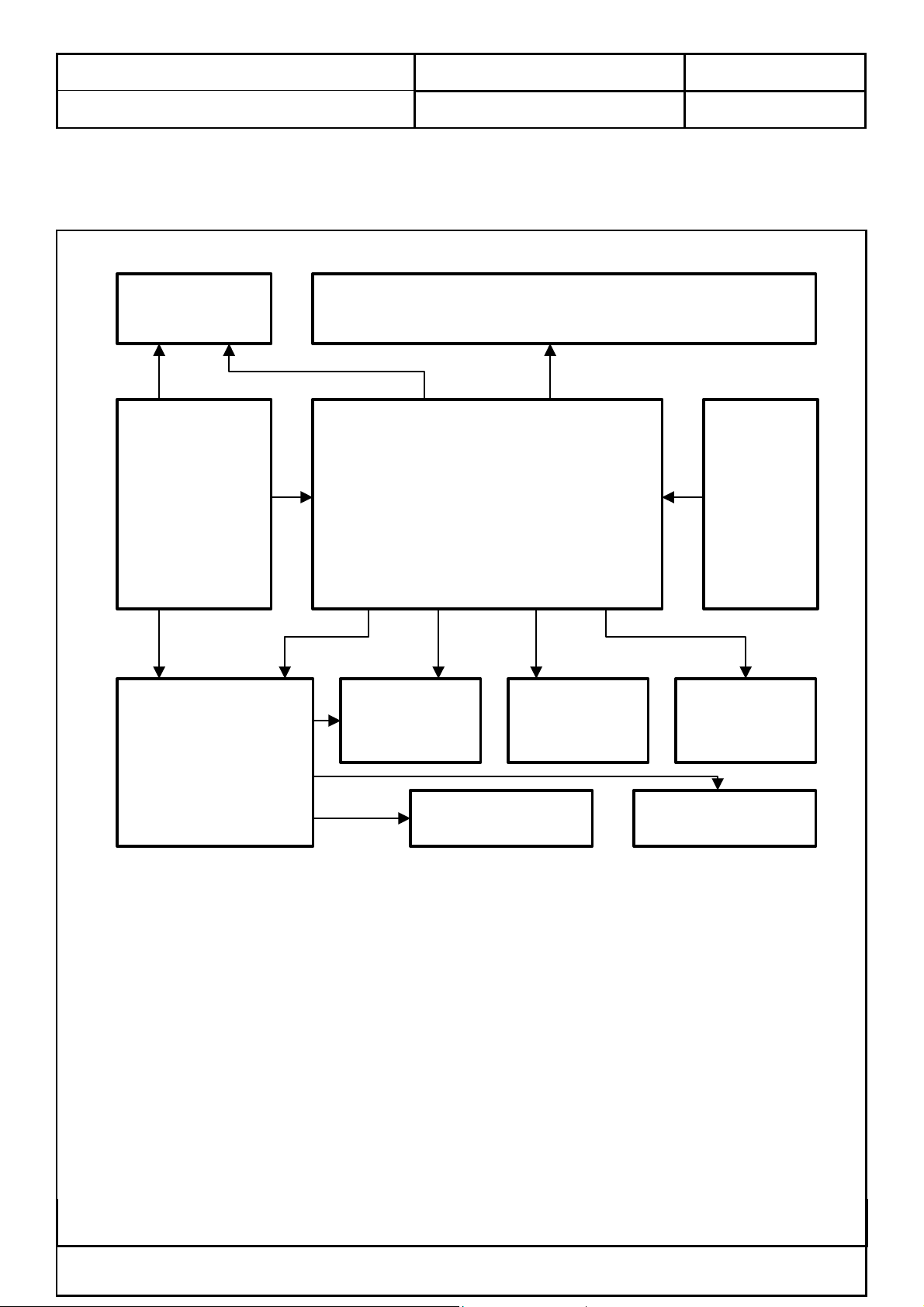
2.2 Block Diagram
2.2.1 System Block & Wiring Diagram
INVERTER
connector 12pin
POWER/B
connector 8pin
connector 4pin
connector 10pin
connector 7pin
DOC NO.: Rev: 1.0
PANEL
panel-20pin
AIN/B
IO/B
Tuner
SCART RGB
SCART YU
connector 62pin
connector 12pin
4pin
V 3
connector
connector 5pin
IR Recever
connector 8pin
KEY/B
UDIO/B
connector 2pin
SPEAKER-L
connector 3pin
SPEAKE
-
This Information Is Confidential And Proprietary To Quanta And Shall Not Be Reproduced Or Otherwise Disclosed
To Anyone Other Than Quanta Employees Without Written Permission From Quanta Computer Inc.
FORM NO.:QF-00001 REV. 3C
Quanta Computer Inc.
Subject:
Effective Date: 2004/04/29 Page
6
of 70
Product Specification of VB1 ( EUROPE )
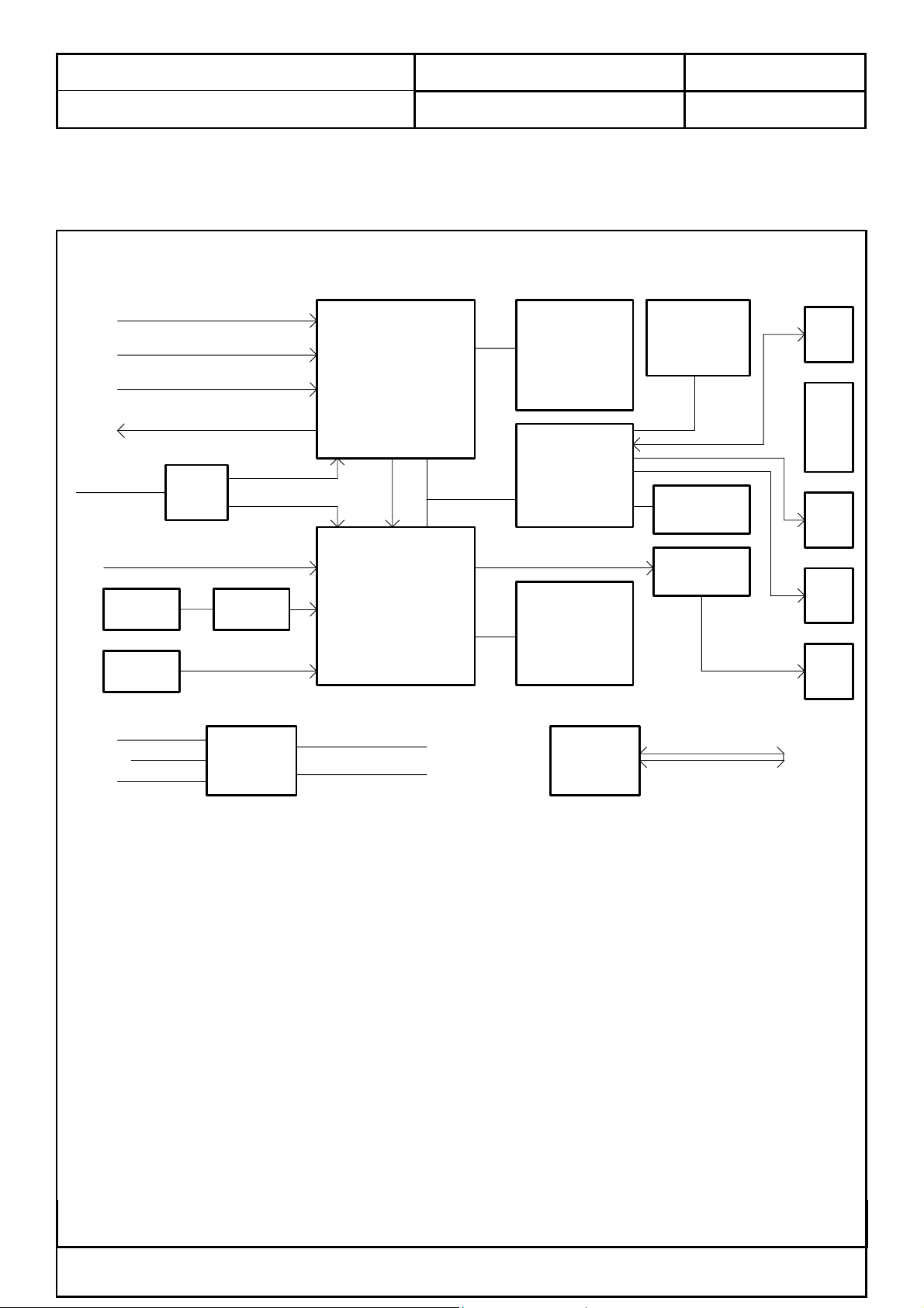
2.2.2 LCD Main Board Block Diagram
TV / AV input
S_Video input
AV3 IN
VIDEO OUT
Component
input
TELX_R.G.B
CON1
DVI_IN
CON3
D_SUB
U10
Y/Cb/Cr
4053
Y/Pb/Pr
U2
SIL169
R.G.B.Hs.Vs
U13
DPTV
IN
Y.U.V
U22
PMM
DOC NO.: Rev: 1.0
U31
W29C040
512K
U33
W24257AJ
U30
TH63L83R
SDA/SCL
1M*16 * 4
4M * 64
SDRAM
W981616BH
U21
MCU
W78C438
2M*32 * 2
4M * 64
SDRAM
W986432DH
CON13
KPD
CON12
12V
5Vs
5V
CON11
LCD
ON/OFF
CON15
LED
IR
CON10
LVDS
OUT
PC AUDIO
AUDIO 3 IN
AUDIO IN
U9
4052
AUDIO SW
AUDIO LOUT TO AMP BOARD
AUDIO ROUT TO AMP BOARD
U11
4053
AV3 IN/OUT
SW
Components are subject to be
changed without prior notice.
CON6
This Information Is Confidential And Proprietary To Quanta And Shall Not Be Reproduced Or Otherwise Disclosed
To Anyone Other Than Quanta Employees Without Written Permission From Quanta Computer Inc.
FORM NO.:QF-00001 REV. 3C
Quanta Computer Inc.
Subject:
Effective Date: 2004/04/29 Page
7
of 70
Product Specification of VB1 ( EUROPE )
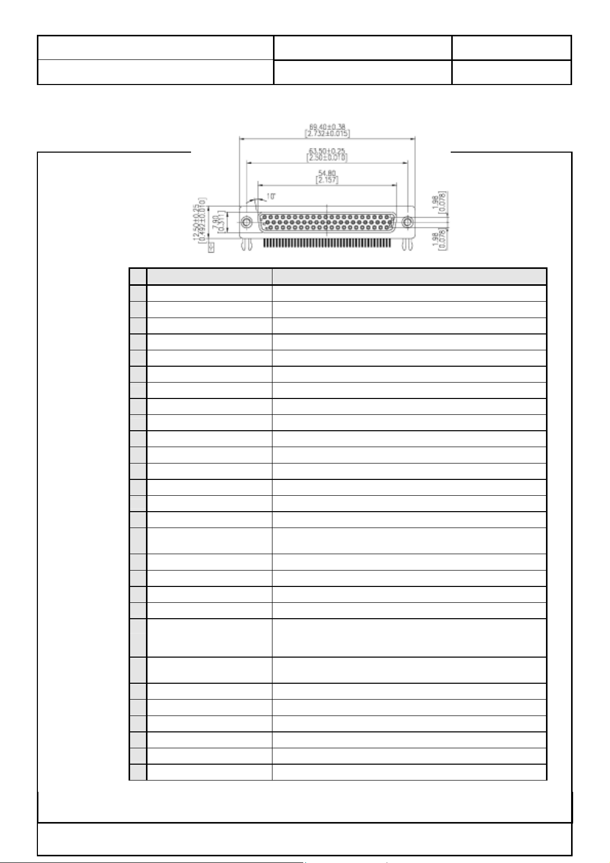
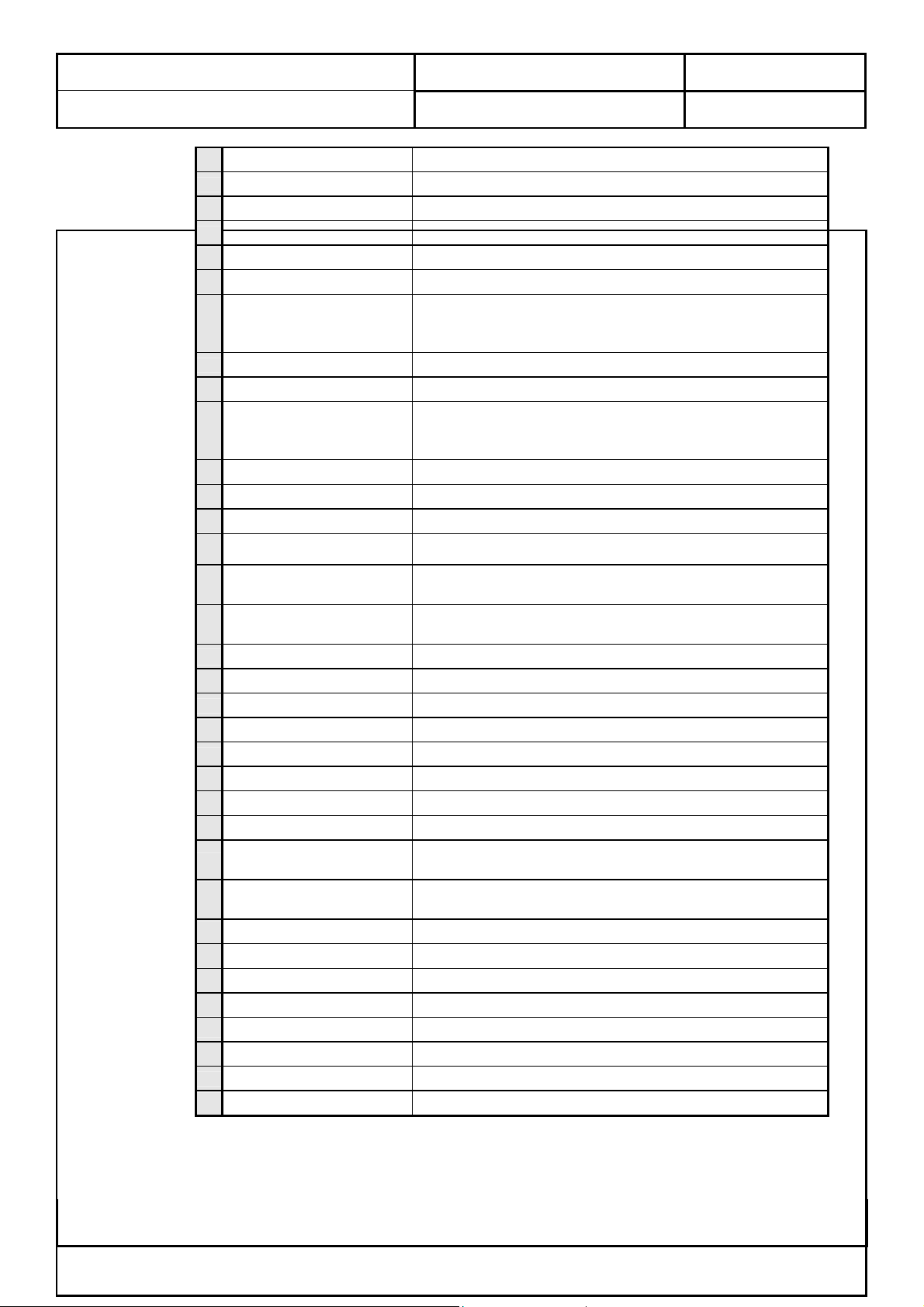
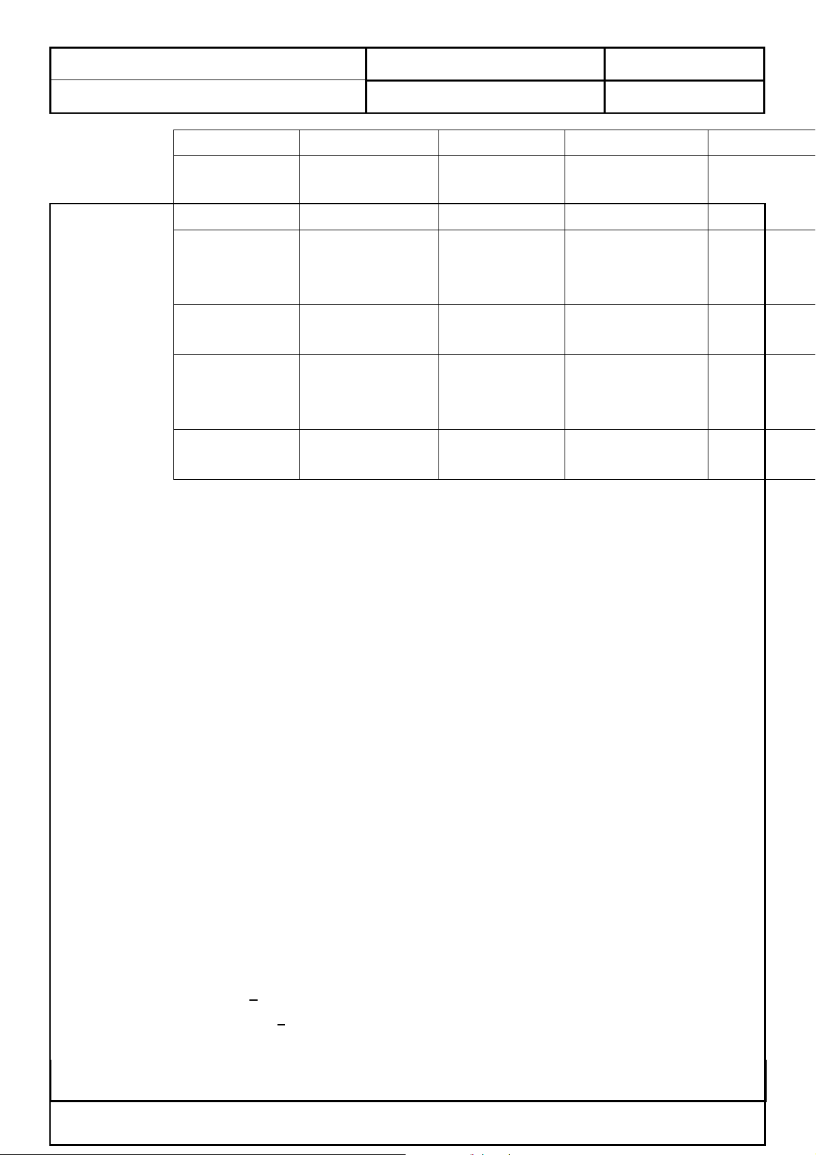
2.2.3 Pin Definition Between Main Board and I/O Board
No. Signal Name Function
1 Teletext_RGB_B ( 6 ) ‘ Blue ’ signal comes from Teletext decoder IC.
2 Teletext_RGB_G ( 6 )
3 Teletext_RGB_R ( 6 )
4 Teletext_fast_blanking
5 Teletext_start
6 SCART_aspect_ratio_1
7 DAC_RST ( 1 )
8 TX_232 ‘ TX ’ signal of UART
9 SVHS_2_C ( 3 ) ‘ Chrominance ’ signal of SVHS-2
10 SVHS_1_Return ( 3 ) Return path paired with Y and C of SVHS-1
11 SVHS_1_Y ( 3 ) ‘ Y ’ of SVHS signal set 1.
12 CVBS_1_Signal ( 2 ) CVBS-1
13 GND_1_of_( 3 ) Power ground
14 Audio_Center_Gnd_gnd ( 2 ) ‘ Ground ’ path paired with audio ‘ Center ’
15 Earphone_for_subpicture_L ( 2 ) Audio ‘ Left ’ channel paired with sub-picture.
16 Audio_Woofer_Gnd_woofer ( 2 )
17 Audio_Rear_L_R_Gnd_of_R ( 3 ) ‘ Right ’ signal of audio rear channels.
18 YUV_1_Pr ( 6 ) ‘ Pr ’ of YUV signal set 1.
19 YUV_1_Pb ( 6 ) ‘ Pb ’ of YUV signal set 1.
20 YUV_1_Y ( 6 ) ‘ Y ’ of YUV signal set 1.
21 Audio_Front_L_R_Gnd_of_R ( 3 )
22 Teletext_Vs ( 3, from main board )
23 Teletext_RGB_B_Return ( 6 )
24 Teletext_RGB_G_Return ( 6 )
25 Teletext_RGB_R_Return ( 6 )
26 GND_2_of_( 3 ) Power ground
27 SCART_mode_det_1 SCART mode detection ( RGB or CVBS )
28 RESET_I_O_Module LCDTV main board uses this pin to reset all components inside the I/O module.
DOC NO.: Rev: 1.0
‘ Green ’ signal comes from Teletext decoder IC.
‘ Red ’ signal comes from Teletext decoder IC.
Fast blanking signal for the use of Teletext decoder IC on I/O module.
Main board issues it for the use of Teletext decoder IC on the I/O module.
Aspect ratio indictor signal comes from pin-16 of ordinary SCART connector.
Main board used this pin to reset I
Audio woofer signal. After decoding Dolby digital or other surround audio, digital
receiver sends this woofer signal to LCDTV main board for further processing.
‘ Right ’ channel of surround audio.
After decoding Dolby digital or other surround audio, digital receiver sends this
signal to LCDTV main board for further processing.
Vertical Sync. Signal issued by LCDTV main board for use of Teletext decoder IC
on the I/O module.
‘ Blue ’ signal return for Teletext decoder IC.
Return path paired with ‘ Green ’ signal comes from Teletext decoder IC.
Return path of ‘ Red ’ signal comes from Teletext decoder IC.
2
C DAC on current I/O module.
This Information Is Confidential And Proprietary To Quanta And Shall Not Be Reproduced Or Otherwise Disclosed
To Anyone Other Than Quanta Employees Without Written Permission From Quanta Computer Inc.
FORM NO.:QF-00001 REV. 3C
Quanta Computer Inc.
t
y
d
d
Subject:
Effective Date: 2004/04/29 Page
8
of 70
Product Specification of VB1 ( EUROPE )
29 RX_232 ‘ RX ’ signal of UART
30 SVHS_2_Return ( 3 ) Return path paired with Y and C of SVHS-2
31 SVHS_2_Y ( 3 ) ‘ Y ’ of SVHS signal set 2.
32 SVHS_1_C ( 3 ) ‘ Chrominance ’ signal of SVHS-1.
33 CVBS_1_Return ( 2 ) Return path for CVBS-1
34 CVBS_2_Signal ( 1 ) CVBS-2
35 Audio_Center_Gnd_signal ( 2 )
36 Earphone_for_subpicture_R ( 2 ) Audio ‘ Right ’ channel paired with sub-picture.
37 Audio_Woofer_Gnd_gnd ( 2 ) Ground signal paired with audio ‘ Woofer ’ channel.
38 Audio_Rear_L_R_Gnd_of_gnd ( 3 )
39 YUV_1_Pr_Return ( 6 )
40 YUV_1_Pb_Return ( 6 )
41 YUV_1_Y_Return ( 6 )
Audio_Front_L_R_Gnd_of_Gnd
42
( 3 )
43 Teletext_Hs ( 3, from main board )
44
Teletext_Hs_Vs_return ( 3 )
45
TV_Out Video output for signal set AV3_OUT
46 TV_R Audio ‘ Right ’ channel of signal set AV3_OUT
47 TV_L Audio ‘ Left ’ channel of signal set AV3_OUT
48 Audio_Mute
49 12V_max_1A_a ( 2 )
50 12V_max_1A_b ( 2 )
51 5V_max_1.5A_a ( 2 )
52 5V_max_1.5A_b ( 2 )
53 USDA
54
USCL
55 ID_1 Identification signal -1
56 ID_2 Identification signal -2
57 GND_3_of_( 3 ) Power ground
58 Audio_Rear_L_R_Gnd_of_L ( 3 ) Audio ‘ Left ’ channel paired with sub-picture.
59 YUV_2_Pr ( 3 ) ‘ Pr ’ signal of YUV-2 signal set.
60 YUV_2_Pb ( 3 ) ‘ Pb ’ signal of YUV-2 signal set.
61 YUV_2_Y ( 3 ) ‘ Y ’ signal of YUV-2 signal set.
62 Audio_Front_L_R_Gnd_of_L ( 3 ) ‘ Left ’ signal of audio rear channels.
DOC NO.: Rev: 1.0
‘ Center ’ signal of surround audio channels.
After decoding Dolby digital or other surround audio, digital receiver sends this
signal to LCDTV main board for further processing.
Ground signal of rear left and right audio channels.
After decoding Dolby digital or other surround audio, digital receiver sends this
signal to LCDTV main board for further processing.
Return path of ‘ Pr ’ signal. It belongs to YUV signal set –1.
Return path of ‘ Pb ’ signal. It belongs to YUV signal set –1.
Return path of ‘ Y ’ signal. It belongs to YUV signal set –1.
‘ Ground ’ path paired with audio front “ Left ” and “ Right ”
Horizontal Sync signal. LCDTV main board issues it for the use of Teletex
decoder IC on the I/O module.
Common return path of horizontal and vertical sync signals which are issued b
LCDTV main board
Disable all the analog audio signals from I/O modules
Power pins which supply +12V to digital receiver.
Power pins which supply +12V to digital receiver.
Power pins which supply +5V to digital receiver.
Power pins which supply +5V to digital receiver.
SDA signal issued by LCDTV main board to access ICs an
modules of analog option
SCL signal issued by LCDTV main board to access ICs an
modules of analog option
This Information Is Confidential And Proprietary To Quanta And Shall Not Be Reproduced Or Otherwise Disclosed
To Anyone Other Than Quanta Employees Without Written Permission From Quanta Computer Inc.
FORM NO.:QF-00001 REV. 3C
Quanta Computer Inc.
Subject:
Effective Date: 2004/04/29 Page
9
of 70
Product Specification of VB1 ( EUROPE )
3.0 LCD Panel Characteristics
3.1 General Description
This LCD TV adopts QDI and LG’s display modules which are color active matrix thin
film transistor ( TFT ) liquid crystal display ( LCD ) that uses amorphous silicon TFT as a
switching device. This model is composed of a TFT LCD panel, a driving circuit and a
backlight system.
This TFT LCD has a 23.01 inch diagonally measured active display area with WXGA
resolution ( 768 vertical by 1280 horizontal pixel array ).
( Please refer to panel specification for detail and updated information )
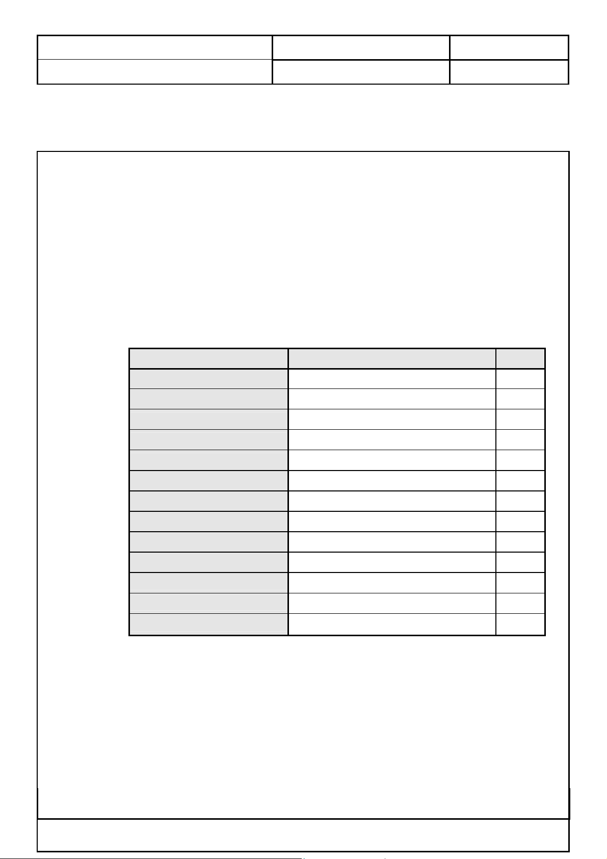
3.2 General Information
Item Specification
DOC NO.: Rev: 1.0
Unit
Outline Dimension
Display area
Number of pixel
Pixel pitch
Pixel arrangement
Display color
Display mode
Surface treatment
Weight
Back-light
Input signal
Power consumption
Optimum viewing direction
528.0 x 326.0 x 38.6 mm
23.01 inches ( 584.40 mm ) Diagonal inch
1280 ( H ) x 768 ( V ) pixels
0.3915 x 0.3915 x RGB mm
RGB Vertical stripe
16.7 M colors
Normally white
Antiglare, Hard-Coating ( 3H )
Max.2700 g
12 CCFLs
1-ch LVDS
70 W
6 o’clock
This Information Is Confidential And Proprietary To Quanta And Shall Not Be Reproduced Or Otherwise Disclosed
To Anyone Other Than Quanta Employees Without Written Permission From Quanta Computer Inc.
FORM NO.:QF-00001 REV. 3C
Quanta Computer Inc.
r eq
Subject:
Effective Date: 2004/04/29 Page
10
of 70
Product Specification of VB1 ( EUROPE )
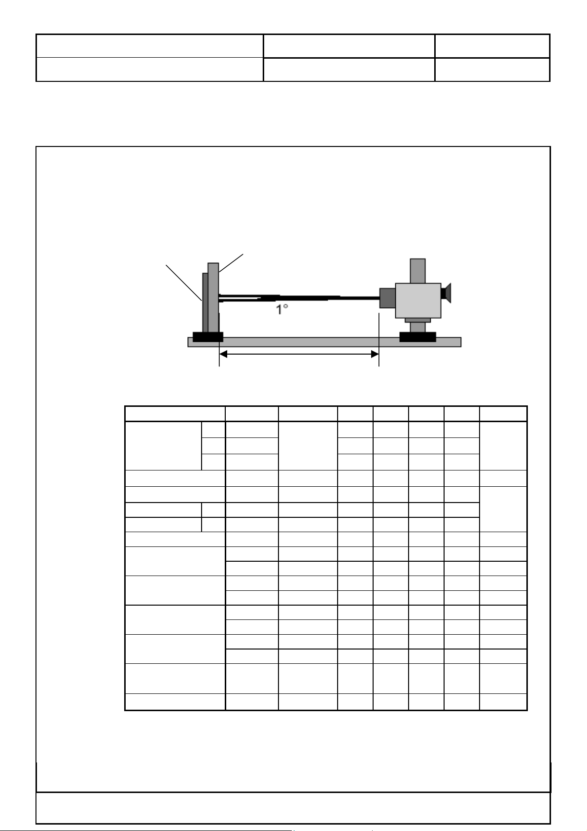
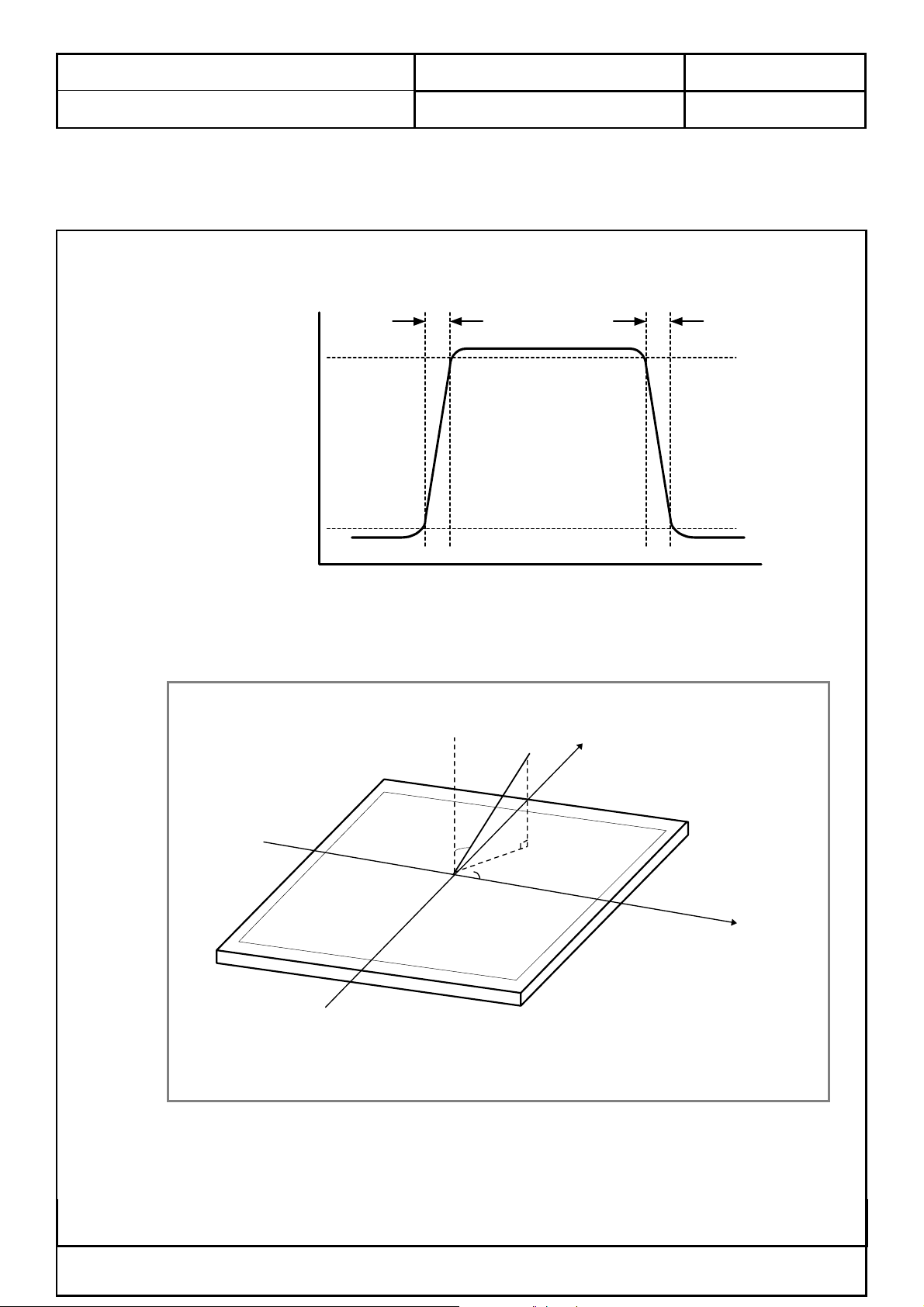
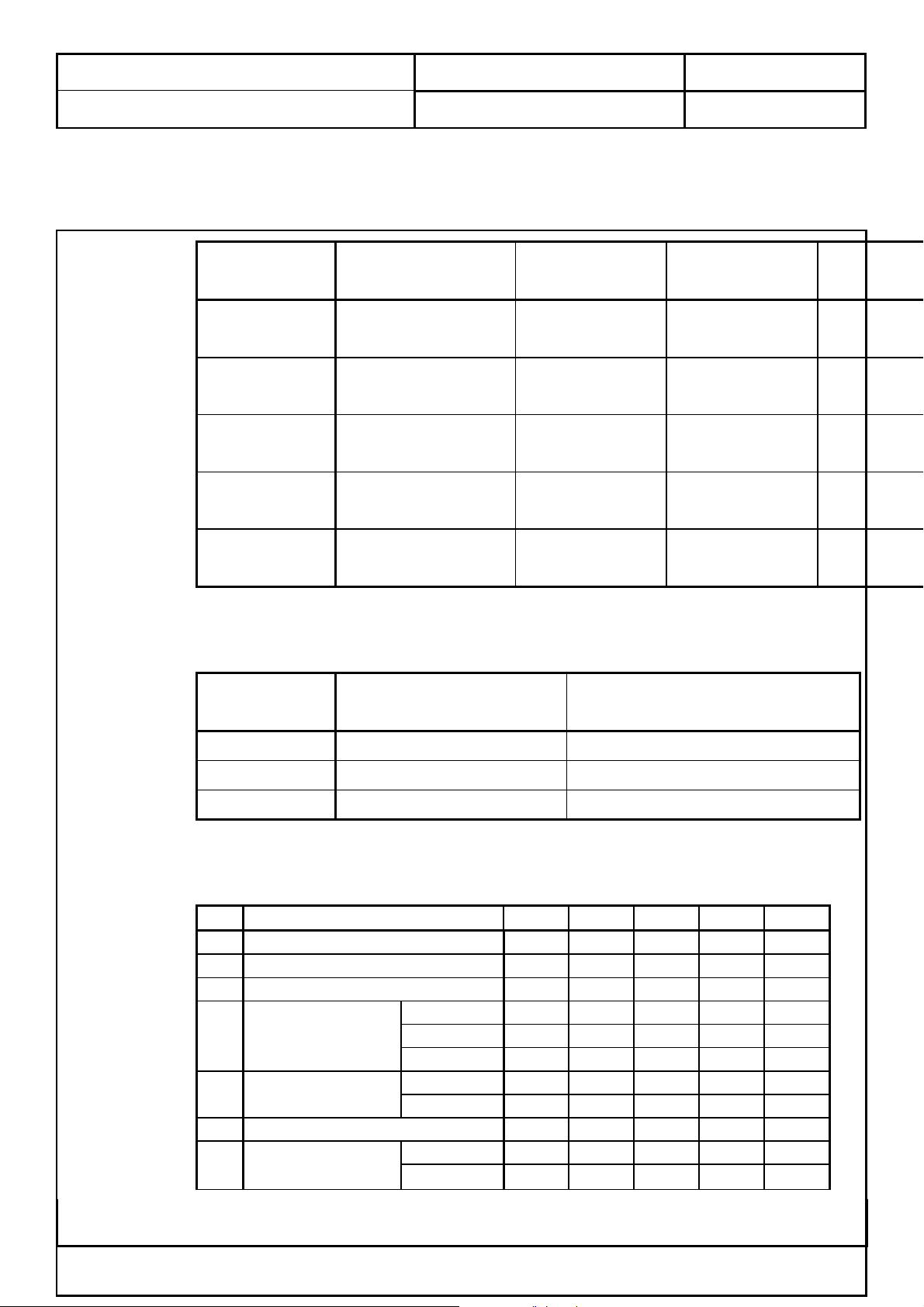
3.3 Optical Characteristics
Optical characteristics are determined after the unit has been ‘ON’ and stable for arround 2
Hrs in a dark environment at 25 °C. The values specified are at an approximate distance 50 cm
from the LCD surface at a viewing angle of F and q equal to 0 °.
FIG. 1 Optical Characteristic Measurement Equipment and Method
Optical Stage ( x , y )
Parameter Symbol Condition Min. Typ. Max. Unit Remark
Viewing angle
range
Contrast ratio
Response time
Rise time
Fall time
Gray to gray
Chromaticity of
White ( CIE 1931 )
Chromaticity of
Red ( CIE 1931 )
Chromaticity of
Green ( CIE 1931 )
Chromaticity of
Blue ( CIE 1931 )
Luminance of
white
【 Note4 】
White Uniformity
LCD Module
L/R
θ
U
D
τr
τd
δ
21,θ22
θ
θ
CR
τ
Wx 0.255 0.285 0.315
Wy 0.264 0.294 0.324
Rx 0.611 0.641 0.671
Ry 0.312 0.342 0.372
Gx 0.245 0.275 0.305
Gy 0.583 0.613 0.643
Bx 0.117 0.147 0.177
By 0.055 0.085 0.115
Y
W
DOC NO.: Rev: 1.0
Pritchard 880
o
uivalent
500m
Ta:25±2 °C, V
Dclk:80MHz, Luminance Ratio:100%
:12.0V, fV:60Hz,
LCD
85 Deg.
Note 5
11
12
n
CR>10
θ=0°
85 Deg.
85 Deg.
400 600
21 ms
−
−
15 ms
【
【
【
Note1
Note 4
】
】
】
6 ms
16 ms
Note 2
L
( 5P )
- 450 Cd/m2
- 1.25
−
【
【
Note 3
】
】
The measurement shall be executed 30 minutes after lighting at rating.
※
This Information Is Confidential And Proprietary To Quanta And Shall Not Be Reproduced Or Otherwise Disclosed
To Anyone Other Than Quanta Employees Without Written Permission From Quanta Computer Inc.
FORM NO.:QF-00001 REV. 3C
Quanta Computer Inc.
g
p
H
V
B
Subject:
Effective Date: 2004/04/29 Page
11
of 70
Product Specification of VB1 ( EUROPE )
DOC NO.: Rev: 1.0
Notes: 1. Contrast Ratio ( CR ) is defined mathematically as:
Surface Luminance with all white pixels
Contrast Ratio =
Surface Luminance with all black pixels
2. Surface luminance is the center point ( 1 ) across the LCD surface 50 cm from the
surface with all pixels displaying white under the condition of IBL = 6 mArms. For more
information see FIG 1.
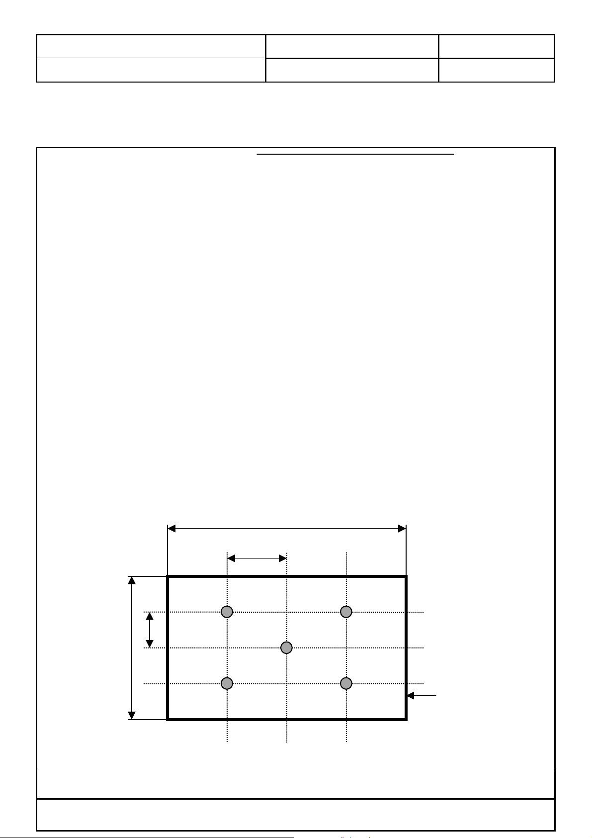
3. The variation in surface luminance , δ WHITE is defined by measuring LON at watch
test position 1 through 5, and then dividing maximum LON of 5 points luminance by
minimum LON of each 5 points luminance. For more information see FIG 2.
δ WHITE = Maximum (LON1, LON2, ..., LON5 ) / Minimum (LON1, LON2, ..., LON5 )
4. Response time is the time required for the display to transition from black to white
( Rise Time, TrR ) and from white to black ( Decay Time, TrD ). For additional information
see FIG 3.
5. Viewing angle is the angle at which the contrast ratio is greater than 10. The angles are
determined for the horizontal or x axis and the vertical or y axis with respect to the z axis
which is normal to the LCD surface. For more information see FIG 4.
FIG. 2 Luminance
A : H/4 mm,
B : V/4 mm,
L3L2
H : 501.12 mm
V : 300.67 mm
L1
@ H,V : Active Area
L5L4
< measuring point for surface luminance & measurin
This Information Is Confidential And Proprietary To Quanta And Shall Not Be Reproduced Or Otherwise Disclosed
To Anyone Other Than Quanta Employees Without Written Permission From Quanta Computer Inc.
FORM NO.:QF-00001 REV. 3C
oint for luminance variation >
Active Area
Quanta Computer Inc.
Subject:
Effective Date: 2004/04/29 Page
12
of 70
Product Specification of VB1 ( EUROPE )
FIG. 3 Response Time
The response time is defined as the following figure and shall be measured by switching the
input signal for “ black ” and “ white ”.
Optical
Response
100
90
10
0
DOC NO.: Rev: 1.0
TrR
TrD
FIG. 4 Viewing angle
φ
= 180°, Left
φ
= 270°, Down
Normal
θ
E
φ
Y
φ
= 90°, Up
φ
= 0°, Right
< Dimension of viewing angle range >
This Information Is Confidential And Proprietary To Quanta And Shall Not Be Reproduced Or Otherwise Disclosed
To Anyone Other Than Quanta Employees Without Written Permission From Quanta Computer Inc.
FORM NO.:QF-00001 REV. 3C

Quanta Computer Inc.
Subject:
Effective Date: 2004/04/29 Page
13
of 70
Product Specification of VB1 ( EUROPE )
DOC NO.: Rev: 1.0
4.0 Display Electrical and Functional Specifications
4.1 Input and Output Signals
This LCD TV shall have the ability to operate under following range with stable green
color of LED indicated. Any signal outside of the limits ( any combination ) shall not cause
any damage to the unit or driving source. The range of operation is:
CVBS and Y/C:
PAL ( 4.43 M , 50 Hz ) B、G、D、K、H、I, PAL ( 4.43 M , 60 Hz )
SECAM D、K
NTSC ( 3.58 M ), NTSC ( 4.43 M ), Japan ( 50 Hz )
TV Systems:
PAL and SECAM system Receivable
Full frequency range From channel E2 ( 48.25 MHz ) to channel E69 ( 855.25 MHz )
YUV Inputs:
YCbCr ( 480i )
YPbPr ( 480p、1080i、720p )
VGA and DVI-D Inputs:
Horizontal input frequency range: 30k Hz to 70k HZ
Vertical input frequency range: 56 Hz to 85 Hz
Max. Resolution: 1280 x 768
Down Scaling support: 1152 x 870 75 Hz
1280 x 960 60 / 85 Hz
1280 x 1024 60 / 75 / 85 Hz
The LED shall indicate amber color and OSD will show “ Out of Range “ message within
5 seconds after signal is out of range or down scaling support from selected input.
This LCD TV shall catch signal sources from TV
、AV1、RGB、AV2、YUV、AV3、
VGA and DVI-D automatically during power up, which it is unnecessary to select inputs from
OSD or hot keys. The priority to catch signal sources shall be 1st) User selected source from
hot key or OSD, 2nd) Last source used, 3rd) TV input ( last power down channel), 4th) AV1
RGB input, 5th) AV1 S input, 6th) AV1 CVBS input, 7th) AV2 YUV input, 8th) AV2 S input, 9th)
AV2 CVBS input, 10th) AV3 input ( Set to be input from OSD ), 11th) VGA input, 12th) DVI-D
input. The LCD TV shall complete selection and show media on screen within 5seconds
( including Auto Adjust ).
The LED shall indicate amber color and OSD will show “ No Signal “ within 3 seconds
while there is missing signal from selected input.
This Information Is Confidential And Proprietary To Quanta And Shall Not Be Reproduced Or Otherwise Disclosed
To Anyone Other Than Quanta Employees Without Written Permission From Quanta Computer Inc.
FORM NO.:QF-00001 REV. 3C

Quanta Computer Inc.
Subject:
Effective Date: 2004/04/29 Page
14
of 70
Product Specification of VB1 ( EUROPE )
The LED shall indicate amber color and OSD will show “ No VGA Connection “ within 5
seconds while VGA input is selected but has no connection on VGA port.
The LED shall indicate amber color and OSD will show “ Go Into Power Save “ within 5
seconds after meet condition of power saving mode.
This LCD TV shall go into power saving state in 5 seconds later of showing “ Go Into
Power Save “. The LED shall indicate amber color with blinking once per three seconds
during power saving mode.
This LCD TV shall proceed Auto Adjust while VGA or DVI-D input is selected and 1)
Power up, 2) Auto Adjust pressed from OSD, 3) Factory preset acted, 4) New mode is detected.
OSD shall show “ Auto Adjustment Proceeding ….. Please Wait “ and LED shall indicate
amber color during auto adjust. Auto adjust shall be completed within 3 seconds.
The AV1 input supports both of S-video and CVBS video inputs. If both of the S-video and
DOC NO.: Rev: 1.0
CVBS video inputs are connected with cables, the S-video input takes priority.
The AV2 input support both of S-video and CVBS video inputs. If both of the S-video and
CVBS video inputs are connected with cables, the S-video input takes priority.
The AV3 could be set either input or output from OSD. While it is set to be output, AV3
would carry CVBS signal and stereo audio out from TV tuner.
This Information Is Confidential And Proprietary To Quanta And Shall Not Be Reproduced Or Otherwise Disclosed
To Anyone Other Than Quanta Employees Without Written Permission From Quanta Computer Inc.
FORM NO.:QF-00001 REV. 3C

Quanta Computer Inc.
Subject:
Effective Date: 2004/04/29 Page
15
of 70
Product Specification of VB1 ( EUROPE )
4.1.1 Video input
4.1.1.1 CVBS Input Signal
Type: Analog
Polarity: Positive
Level: 1 Vp-p ( with Sync.)
Impedance: 75Ω± 5 %
Interface: Euro-SCART
4.1.1.2 S Video Input Signal
Type: Analog
Polarity: Positive
Level: Y: 1 Vp-p ( with Sync.) C: 0.286 Vp-p
Impedance: 75Ω± 5 %
Interface: Euro-SCART
DOC NO.: Rev: 1.0
4.1.1.3 RGB Input Signal
Type: Analog
Polarity: Positive
Level: 0.7 Vp-p
Impedance: 75Ω± 5 %
Interface: Euro-SCART
4.1.1.4 YUV ( YCbCr or YPbPr ) Input Signal
Type: Analog
Polarity: Positive
Level: Y: 1 Vp-p ( with Sync.) U/V: 0.7 Vp-p
Impedance: 75Ω± 5 %
Interface: Euro-SCART
This Information Is Confidential And Proprietary To Quanta And Shall Not Be Reproduced Or Otherwise Disclosed
To Anyone Other Than Quanta Employees Without Written Permission From Quanta Computer Inc.
FORM NO.:QF-00001 REV. 3C

Quanta Computer Inc.
Subject:
Effective Date: 2004/04/29 Page
16
of 70
Product Specification of VB1 ( EUROPE )
4.1.2 Audio input, output and Speaker
4.1.2.1 Audio input
Level: 500 mVrms
Type: Stereo R/L Channels
Impedance: More than 22 kΩ
Interface: Euro-SCART
4.1.2.2 PC Stereo Input
Level: 500 mVrms
Type: Stereo R/L Channels
Impedance: More than 22 kΩ
Interface: 3.5 mm∮Stereo jack, Pantone 577C, Lime color
4.1.2.3 Headphone output:
DOC NO.: Rev: 1.0
Level: 0.5 W rms/per Channel ( typ. ) for 16 ohm earphone
Type: Stereo R/L Channels
Interface: 3.5 mm∮Stereo jack, Pantone 157C, Orange color
4.1.2.4 Built-in Speaker
Max. Audio output ( at 10 % THD max. ) at 1.0 Vp-p / 1k Hz input: 5 W + 5 W
Sound Distortion at 250 mW / 1 kHz: 1 % THD max
Speaker: 10 W ( 5 W + 5 W )
Speaker impedance: 4 ohms at 1 kHz
Residual Hum at Min. Volume: 500 uW Max
Max. Hum at Max. Volume: 1000 uW Max
4.1.2.5 Audio Line out
Output level: 400 Vrms
Type: stereo R / L channels
Jack: 3.5 mm∮stereo jack
4.1.2.6 Woofer out
2 channels input are mixed to a single
Max. output: 2.5 Vrms ( at f = 100 Hz THD 1 % )
Cross-over frequency: 100 Hz
This Information Is Confidential And Proprietary To Quanta And Shall Not Be Reproduced Or Otherwise Disclosed
To Anyone Other Than Quanta Employees Without Written Permission From Quanta Computer Inc.
FORM NO.:QF-00001 REV. 3C
Quanta Computer Inc.
Subject:
Effective Date: 2004/04/29 Page
17
of 70
Product Specification of VB1 ( EUROPE )
4.1.3 RF Input ( Philips FQ1216ME MK3 )
4.1.3.1 Intermediate Frequencies
No
.
1
2 Colour
3 Sound 1
4 Sound 2 - -
5 NICAM
DOC NO.: Rev: 1.0
M
Carrier
SYSTE
Picture
0
7
0
5
L L’
38.9
5 0
34.4
8 7
32.4
0 0
33.0
0 5
33.9
38.3
40.4
6
39.8
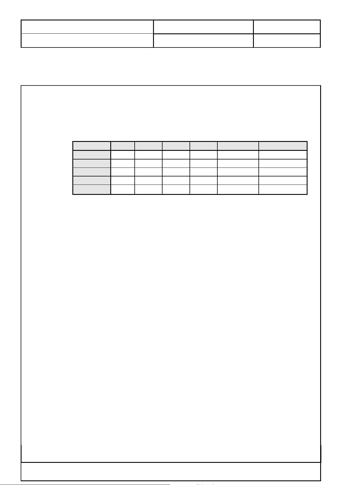
4.1.3.2 Channel Coverage
No
.
1 Low band 48.25 to 160.00 MHz
2 Mid band 160.00 to 442.00 MHz
3 High band 442.00 to 863.25 MHz
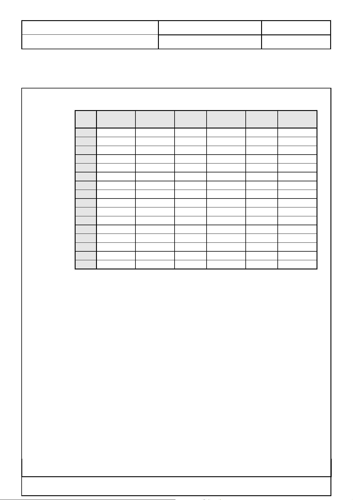
4.1.3.3 Video and Audio Characteristics
PARAMETER
No.
Video output level
1
Video S/N
2
Noise limiting
3
Video amplitude at
4
discrete frequencies
2 MHz - 0.0 -1.5 dB
3 MHz - -0.5 -2.5 dB
4.43 MHz - -1.0 -4.0 dB
Sound carriers
5
rejection
Audio output level
5
Audio S/N
6
5.5/6.0 MHz 42 - - dB
6.5 MHz 40 - - dB
B/G, D/K, I 50 63 - dB
L/L’
BAND FREQUENCY ( MHz )
MIN. TYP. MAX. UNIT NOTE
0.6 0.9 1.2 Vp-p
40 - - dB
- 38 45 dBuV
350 500 650 mVrms
45 55 - dB
This Information Is Confidential And Proprietary To Quanta And Shall Not Be Reproduced Or Otherwise Disclosed
To Anyone Other Than Quanta Employees Without Written Permission From Quanta Computer Inc.
FORM NO.:QF-00001 REV. 3C
Quanta Computer Inc.
Subject:
Effective Date: 2004/04/29 Page
18
of 70
Product Specification of VB1 ( EUROPE )
Audio sensitivity
7
DOC NO.: Rev: 1.0
B/G, D/K, I
L/L’
- - 40 dBuV
- - 45 dBuV
This Information Is Confidential And Proprietary To Quanta And Shall Not Be Reproduced Or Otherwise Disclosed
To Anyone Other Than Quanta Employees Without Written Permission From Quanta Computer Inc.
FORM NO.:QF-00001 REV. 3C
Quanta Computer Inc.
P
P
Subject:
Effective Date: 2004/04/29 Page
19
of 70
Product Specification of VB1 ( EUROPE )
4.1.4 AV ( Euro – SCART ) Input
4.1.4.1 SCART ( RGB ) Pin Out
21-pin Euro-SCART ( RGB )
PI
N
1
2
3
DOC NO.: Rev: 1.0
Signa
l
Audio
Right output 8
Audio
Right input 9
Audio
Left output
N
PI
10
-Video
Control
for Green
used
Signal
Audio
Earth
Not
N
1
1
1
4
5
6
7
4.1.4.2 SCART ( YUV ) Pin Out
21-pin Euro-SCART ( YUV )
PI
+ Mono
Earth
for Audio 11
Earth
for Blue
Audio
Left input +
Mono
Blue
input
Signa
12
13
14
PI
input
used
for Red
used
Green
Not
Earth
Not
Signal
1
1
2
2
N
1 Audio
2 Audio
This Information Is Confidential And Proprietary To Quanta And Shall Not Be Reproduced Or Otherwise Disclosed
To Anyone Other Than Quanta Employees Without Written Permission From Quanta Computer Inc.
FORM NO.:QF-00001 REV. 3C
l
Right output
Right input
N
8 Audio
-Video
Control
9 Earth
for Y
N
1
1
Quanta Computer Inc.
Subject:
Effective Date: 2004/04/29 Page
20
of 70
Product Specification of VB1 ( EUROPE )
3 Audio
4 Earth
5 Earth
6 Audio
7 U
DOC NO.: Rev: 1.0
10 Not
Left output
+ Mono
11 Y
for Audio
12 Not
for U
13 Earth
Left input +
Mono
14 Not
input
used
input
used
for V
used
1
1
1
2
2
4.1.5 VGA Input
4.1.5.1 Separate and Composite Sync
Level: Low = 0 to 0.8 V, High = 2.0 to 5 V
Polarity: Positive or Negative
Impedance: 1 kΩ or higher
4.1.5.2 Input Signal: ( comply with VESA VSIS, Ver.1, Rev.1)
Level: 0 to 700 mV Positive
Rise/Fall time: <
Overshoot: <
Impedance: 75Ω ± 5 % from DC up to 100 MHz
This Information Is Confidential And Proprietary To Quanta And Shall Not Be Reproduced Or Otherwise Disclosed
To Anyone Other Than Quanta Employees Without Written Permission From Quanta Computer Inc.
FORM NO.:QF-00001 REV. 3C
5 ns
10 % of maximum transition.

Quanta Computer Inc.
Subject:
Effective Date: 2004/04/29 Page
21
of 70
Product Specification of VB1 ( EUROPE )
4.1.5.3 Current Sink and Source
When low level is asserted, the maximum current sink from any single monitor sync input node to the
driver is 2.0 mA. When high level is asserted, the maximum current source from the driver to any single
monitor sync input node is 500 uA.
4.1.5.4 Sync. On Green ( SOG )
Level: 300 mV
Polarity: Negative
Impedance: 1 kΩ or higher
DOC NO.: Rev: 1.0
This Information Is Confidential And Proprietary To Quanta And Shall Not Be Reproduced Or Otherwise Disclosed
To Anyone Other Than Quanta Employees Without Written Permission From Quanta Computer Inc.
FORM NO.:QF-00001 REV. 3C
Quanta Computer Inc.
Subject:
Effective Date: 2004/04/29 Page
22
of 70
Product Specification of VB1 ( EUROPE )
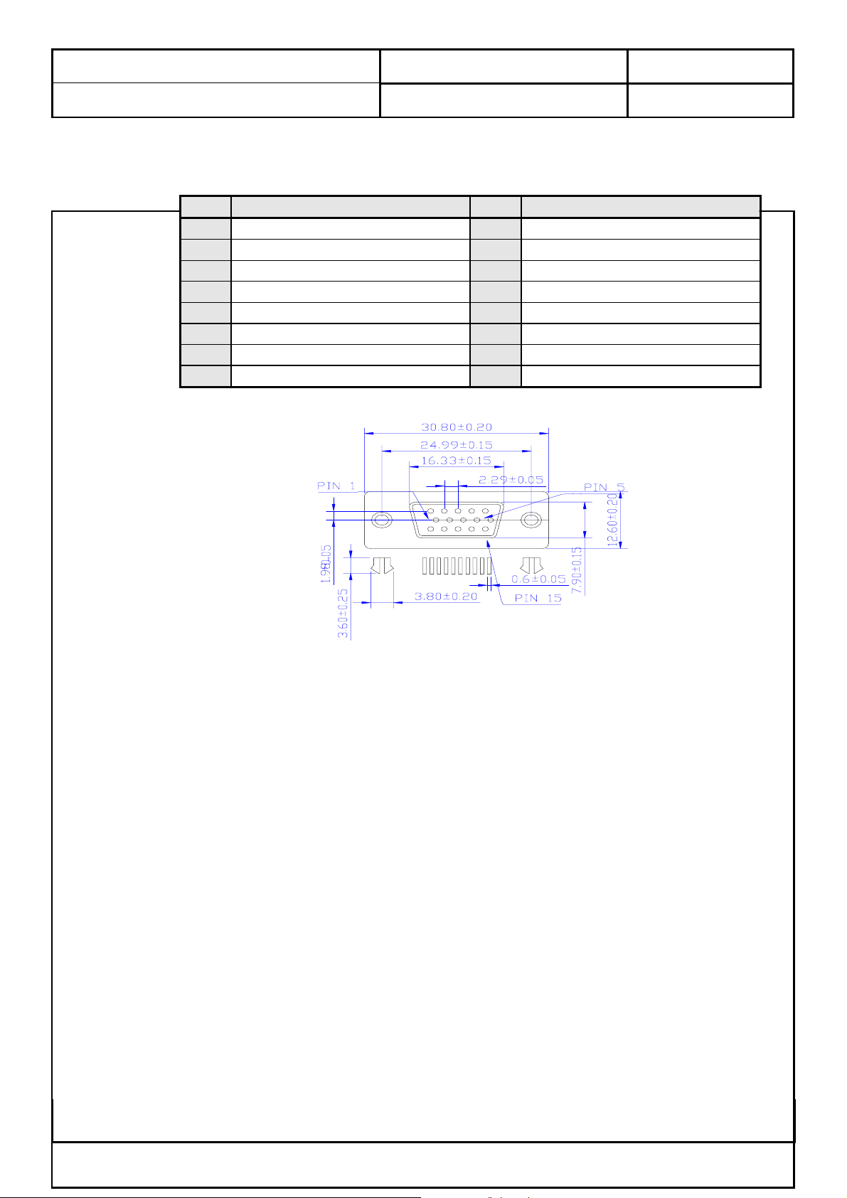
4.1.5.5 D-Sub Pin Out ( Pantone 661C, Blue color )
PIN Signal PIN Signal
1 Red Video 9 +5 V ( PC 97 )
2 Green Video 10 VGA-CONN ( Sync GND )
3 Blue Video 11 Ground
4 Ground 12 SDA ( DDC Data )
5 Ground 13 Horizontal Sync
6 Red Ground 14 Vertical Sync
7 Green Ground 15 SCL ( DDC Clock )
8 Blue Ground
DOC NO.: Rev: 1.0
This Information Is Confidential And Proprietary To Quanta And Shall Not Be Reproduced Or Otherwise Disclosed
To Anyone Other Than Quanta Employees Without Written Permission From Quanta Computer Inc.
FORM NO.:QF-00001 REV. 3C
Quanta Computer Inc.
Subject:
Effective Date: 2004/04/29 Page
23
of 70
Product Specification of VB1 ( EUROPE )
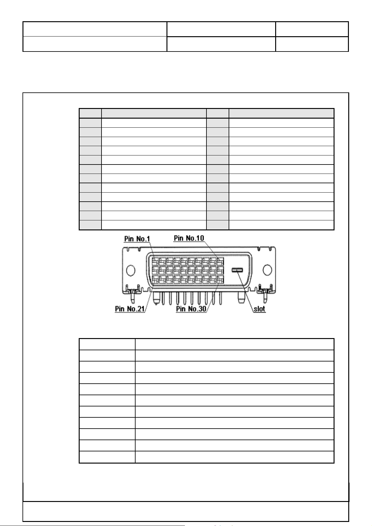
4.1.6 DVI-D Input
Type: Digital
Polarity: Polarity or Negative
PIN Signal PIN Signal
1 TMDS Data 2- 13 TMDS Data 3+
2 TMDS Data 2+ 14 +5 V POWER
3 TMDS Data 2/4 shield 15 Ground ( For +5 V )
4 TMDS Data 4- 16 Hot Plug Detect
5 TMDS Data 4+ 17 TMDS Data 06 DDC Clock 18 TMDS Data 0+
7 DDC Data 19 TMDS Data 0/5 shield
8
9 TMDS Data 1- 21 TMDS Data 5+
10 TMDS Data 1+ 22 TMDS Clock shield
11 TMDS Data 1/3 shield 23 TMDS Clock+
12
No Connect
TMDS Data 3-
DOC NO.: Rev: 1.0
20
24
TMDS Data 5-
TMDS Clock-
4.1.7 Terminals Configuration
RF
AV 1
AV 2
AV 3
PC Analog Port
PC Stereo input
Audio Line Out
Headphone
PC Digital Port
Woofer out
Service Port
75Ω DIN45325 ( IEC169-2 ) Type
Euro-SCART ( RGB ) for Video, S-Video, RGB and Audio
Euro-SCART ( YUV ) for Video, S-Video, YUV and Audio
RCA for Video and Audio R/L
D-Sub 15 pin VGA
3.5 mm∮Earphone Jack
3.5 mm∮Earphone Jack
3.5 mm∮Earphone Jack
DVI-D/HDCP
3.5 mm∮Earphone Jack
ISP through D-Sub
This Information Is Confidential And Proprietary To Quanta And Shall Not Be Reproduced Or Otherwise Disclosed
To Anyone Other Than Quanta Employees Without Written Permission From Quanta Computer Inc.
FORM NO.:QF-00001 REV. 3C
Quanta Computer Inc.
Subject:
Effective Date: 2004/04/29 Page
24
of 70
Product Specification of VB1 ( EUROPE )
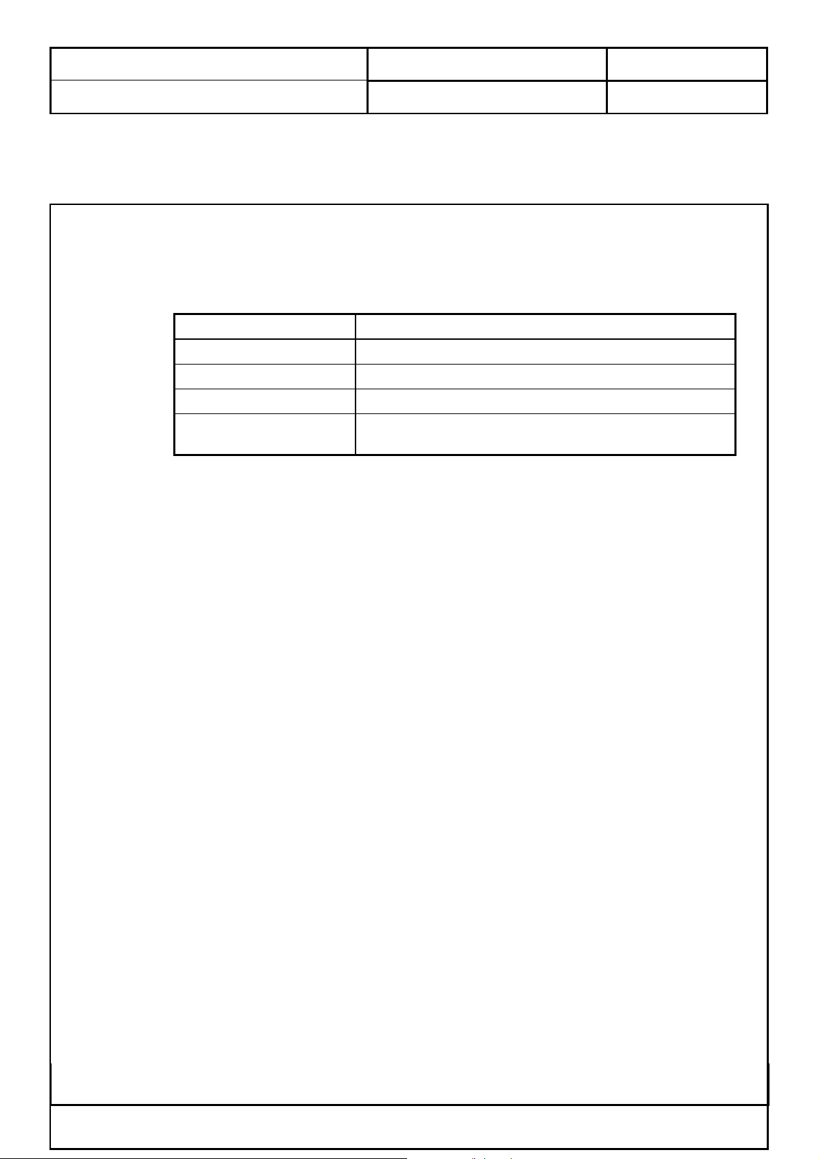
4.2 TV System
This LCD TV could support PAL/SECAM ( CCIR B/G, D/K, I and L/L’) system.
The system allocation as following:
4.2.1 TV System Configurations
Destination PAL/SECAM
Color System
Sound System Sound 1 and Sound 2
Stereo/Bilingual System NICAM and FM Stereo ( A2 )
Channel System
DOC NO.: Rev: 1.0
CCIR B/G, D/K, I and L/L’
Full frequency range from channel E2 ( 48.25 MHz )
to channel E69 ( 855.25 MHz )
4.2.2 De-interlace and Filter
The De-interlace Processor of this LCD TV shall be pixel-based motion and edge adaptive de-
interlacing which converts multiple ( interlaced ) video fields into a single ( progressive scan ) video frame
with twice the number of active scan lines as each of the source fields.
This LCD TV also can detect the input video source sequence automatically. Two types of progressive
scan source sequencing can be detected, i.e. 2:2 pull down and 3:2 pull down.
This LCD TV shall have Motion adaptive 3D digital Y/C separation improves the luma-chroma
separation process such that the luma and chroma are perfectly separated for a stationary image.
This LCD TV shall adopt a motion adaptive filter based noise reduction to successfully determine the
change among frames resulting from noise or moving object.
This Information Is Confidential And Proprietary To Quanta And Shall Not Be Reproduced Or Otherwise Disclosed
To Anyone Other Than Quanta Employees Without Written Permission From Quanta Computer Inc.
FORM NO.:QF-00001 REV. 3C
Quanta Computer Inc.
Subject:
Effective Date: 2004/04/29 Page
25
of 70
Product Specification of VB1 ( EUROPE )
4.3 Firmware Specifications
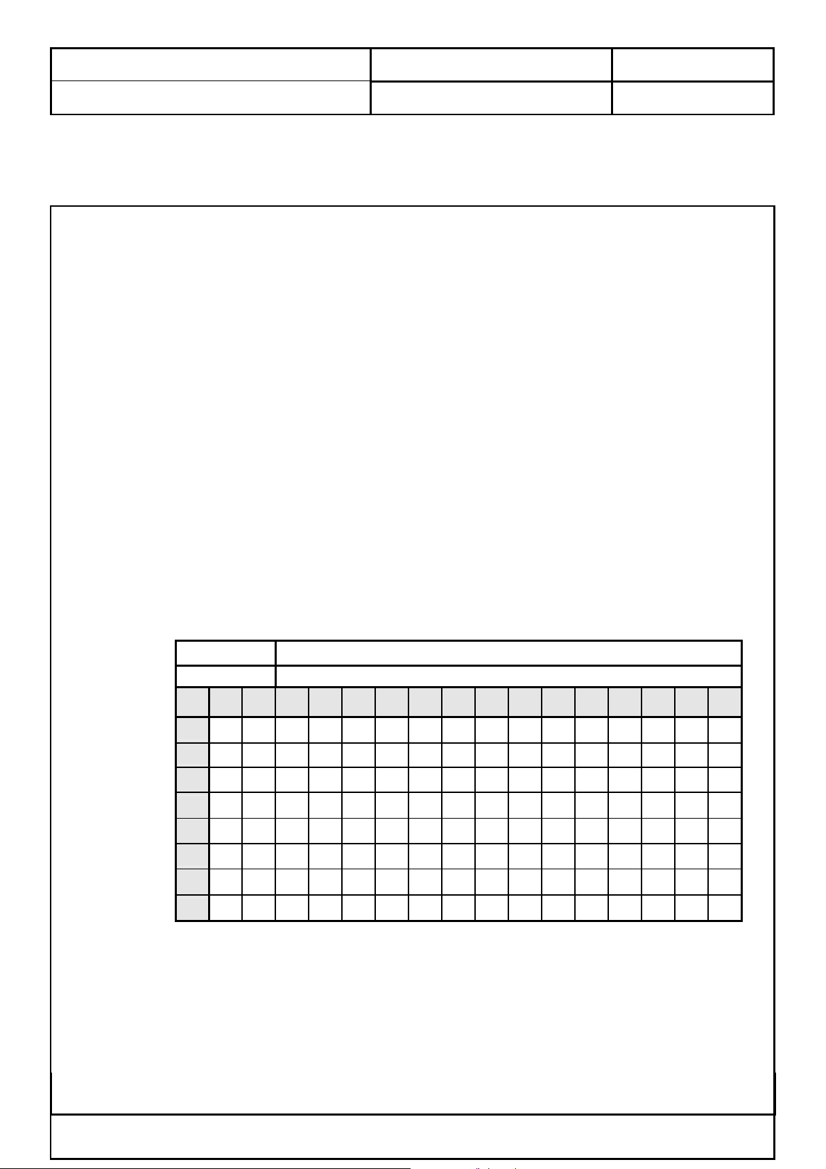
4.3.1 Preset Mode for VGA and DVI-D Inputs
16 factory pre-set modes for VGA and DVI-D inputs are saved during the manufacturing process.
Preset
mode
1 720*400 31.47 - 70 + VGA
2 640*480 31.47 - 60 - VGA
3 640*480 37.861 - 72 - VESA
4 640*480 37.50 - 75 - VESA
5 640*480 43.4 - 85 - VESA
6 800*600 35.156 - 56 + VESA
7 800*600 37.879 + 60 + VESA
8 800*600 48.077 + 72 + VESA
9 800*600 46.875 + 75 + VESA
10 800*600 53.7 + 85 + VESA
11 1024*768 48.363 - 60 - VESA
12 1024*768 56.476 - 70 - VESA
13 1024*768 60.023 + 75 + VESA
14 1024*768 68.7 + 85 + VESA
15 832*624 49.7 - 75 - MAC
16 1024*768 60.2 - 75 - MAC
Pixel
Format
Hor. Freq.
(kHz)
DOC NO.: Rev: 1.0
Hor.
Polarity
Vert. Freq.
(Hz)
Vertical
Polarity
Standard
This LCD TV shall have 10 or more user modes for user to creat own timing.
This LCD TV would detect the used mode automatically.
This Information Is Confidential And Proprietary To Quanta And Shall Not Be Reproduced Or Otherwise Disclosed
To Anyone Other Than Quanta Employees Without Written Permission From Quanta Computer Inc.
FORM NO.:QF-00001 REV. 3C
Quanta Computer Inc.
Subject:
Effective Date: 2004/04/29 Page
26
of 70
Product Specification of VB1 ( EUROPE )
4.3.2 Power Saving
While VGA or DVI-D is selected to be input, this LCD TV is equipped with a power-management
according to VESA DPMS. There is a delay of 5 seconds before the transition from On-state to power saving
state to avoid unintentionally entering of a power saving state during display resolution and timing mode
changes. During the period of delay, the LED shall indicate green color and OSD will show “ GO INTO
POWER SAVE “. Transition from any power saving state to another can be instantaneous. The recovery
from Off-state requires no manual power on.
Mode Hsync Vsync Video Power Indication Recovery time
Power-On On On Active < 130W Green -
Stand-by Off On Off < 5W Amber < 3s
Suspend On Off Off < 5W Amber < 3s
Off-state Off Off Off < 5W Amber < 3s
Power off
× × ×
DOC NO.: Rev: 1.0
< 5W Dark Turn on < 5s
Sync on means: normal operation
Sync off means: Hsync: f<1kHz, duty cycle>25%, Vsync: f<10Hz,duty cycle>25%
The power-consumption is valid over the specified voltage and frequency range.
Power comsuption is measured from AC source.
There are no power saving modes for TV, AV1, AV2, or AV3 inputs.
This Information Is Confidential And Proprietary To Quanta And Shall Not Be Reproduced Or Otherwise Disclosed
To Anyone Other Than Quanta Employees Without Written Permission From Quanta Computer Inc.
FORM NO.:QF-00001 REV. 3C
Quanta Computer Inc.
Subject:
Effective Date: 2004/04/29 Page
27
of 70
Product Specification of VB1 ( EUROPE )
4.3.3 VESA DDC
The VGA and DVI-D inputs shall be capable of continuously transmitting its Extended Display
Identification ( EDID ) information using Display Data Channel. It shall automatically switch to DDC2 mode
if a DDC2 capable host is detected in accordance with the VESA DDC standard.
In addition, the display can respond to a request for EDID, to be transmitted using DDC2, level B
commands. If a DDC2 capable host is detected by the display, the display shall switch to DDC2
communication.
The EDID shall contain the manufacture name code QCI, product code, date of manufacture, and
serial number.
For complete EDID data structure, please refer to VESA Extended Display Identification Data
Standard.
Hardware implementation may be either integrate into micro-controller or be a separate electrical
component. EDID memory must be protected against writing or other corruption through customer-
accessible electrical connection and required communication channels. Password protection, use of an
DOC NO.: Rev: 1.0
unpublished enable register, or use of direct electrical connection is acceptable levels of protection provided
that the power-on Default State is that disabling writing. The serial number fields in the EDID must contain
a unique identifying numbers among units of the same model. EDID Table is defined as below:
For VGA input:
Product Quanta ( internal )
Revision
0 1 2 3 4 5 6 7 8 9 A B C D E F
0 00 FF FF FF FF FF FF 00 1E F9 FC 08 00 00 00 00
1 21 0D 01 03 68 32 1E 78 E8 28 C1 A4 57 46 9D 25
2 12 47 4B AF EE 00 31 59 45 59 61 59 00 00 00 00
3 00 00 00 00 00 00 40 1F 00 70 51 00 2A 30 30 10
4 26 00 08 2C 21 00 00 1E 00 00 00 FD 00 32 55 1E
5 50 08 00 0A 20 20 20 20 20 20 00 00 00 FF 00 31
6 32 33 34 0A 20 20 20 20 20 20 20 20 00 00 00 FC
7 00 47 54 57 2D 4C 32 33 4D 31 30 33 0A 20 00 D1
This Information Is Confidential And Proprietary To Quanta And Shall Not Be Reproduced Or Otherwise Disclosed
To Anyone Other Than Quanta Employees Without Written Permission From Quanta Computer Inc.
FORM NO.:QF-00001 REV. 3C
Quanta Computer Inc.
Subject:
Effective Date: 2004/04/29 Page
28
of 70
Product Specification of VB1 ( EUROPE )
For DVI-D input:
Product Quanta ( internal )
Revision
0 1 2 3 4 5 6 7 8 9 A B C D E F
0 00 FF FF FF FF FF FF 00 1E F9 FC 08 00 00 00 00
1 21 0D 01 03 E8 32 1E 78 E8 28 C1 A4 57 46 9D 25
2 12 47 4B AF EE 00 31 59 45 59 61 59 00 00 00 00
3 00 00 00 00 00 00 40 1F 00 70 51 00 2A 30 30 10
4 26 00 08 2C 21 00 00 1E 00 00 00 FD 00 32 55 1E
5 50 08 00 0A 20 20 20 20 20 20 00 00 00 FF 00 31
6 32 33 34 0A 20 20 20 20 20 20 20 20 00 00 00 FC
7 00 47 54 57 2D 4C 32 33 4D 31 30 33 0A 20 00 51
DOC NO.: Rev: 1.0
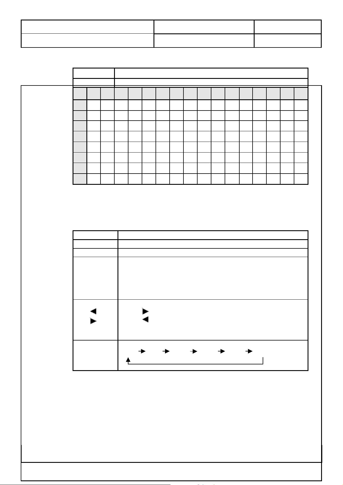
4.3.4 Control Button
Key Function
POWER Software On/Off
MENU/EXIT Press this button to open the OSD or Enter function
When OSD is on:
CH ▲ or
CH ▼
VOL or
VOL
INPUT
Press
Press ▼ key to move icon to down position
When OSD is off:
Press these buttons to select the TV channel in sequence.
When OSD is on:
Press key to increase value or move icon to right position
Press key to decrease value or move icon to left position
When OSD is off:
Press these buttons to select the volume level.
Press this button to select the input :
TV AV1 AV2 AV3 VGA DVI
▲ key to move icon to up position
This Information Is Confidential And Proprietary To Quanta And Shall Not Be Reproduced Or Otherwise Disclosed
To Anyone Other Than Quanta Employees Without Written Permission From Quanta Computer Inc.
FORM NO.:QF-00001 REV. 3C
Quanta Computer Inc.
Subject:
Effective Date: 2004/04/29 Page
29
of 70
Product Specification of VB1 ( EUROPE )
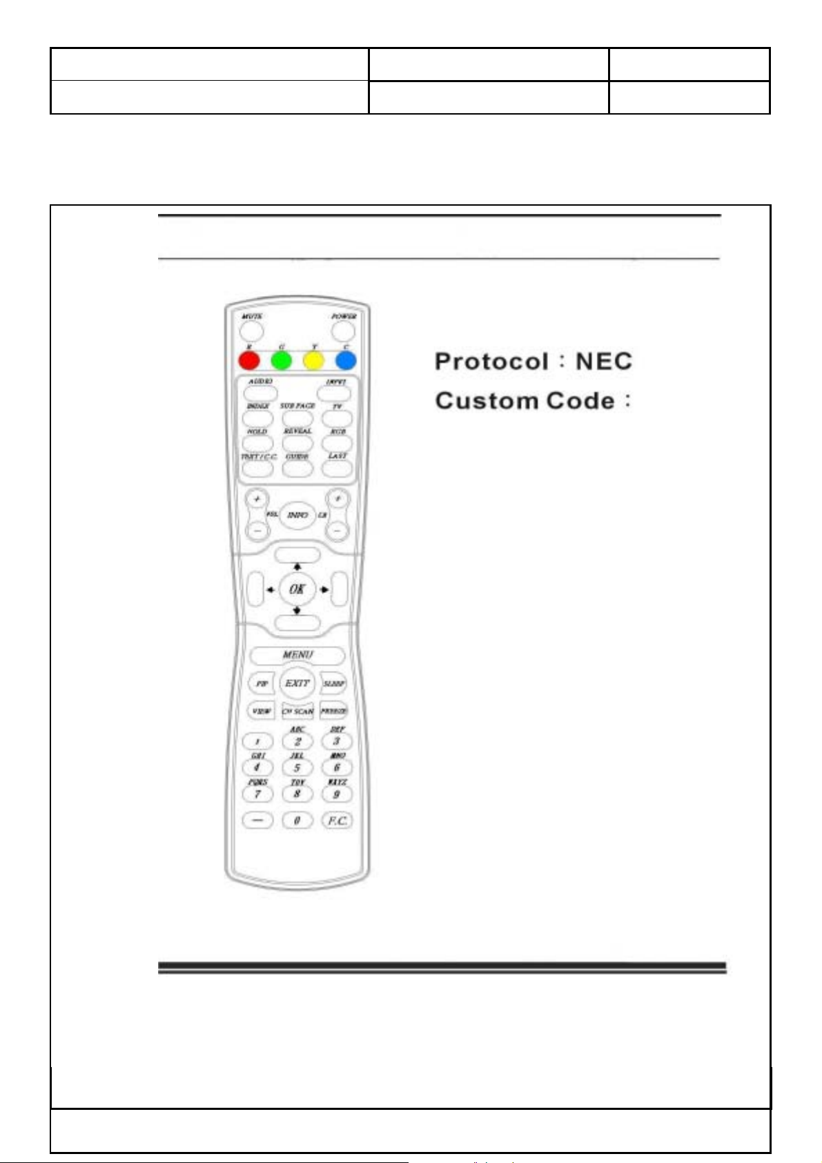
4.3.5 Remote Controller
4.3.5.1 Key Definition
DOC NO.: Rev: 1.0
This Information Is Confidential And Proprietary To Quanta And Shall Not Be Reproduced Or Otherwise Disclosed
To Anyone Other Than Quanta Employees Without Written Permission From Quanta Computer Inc.
FORM NO.:QF-00001 REV. 3C
Quanta Computer Inc.
N
N
r
Subject:
Effective Date: 2004/04/29 Page
30
of 70
Product Specification of VB1 ( EUROPE )
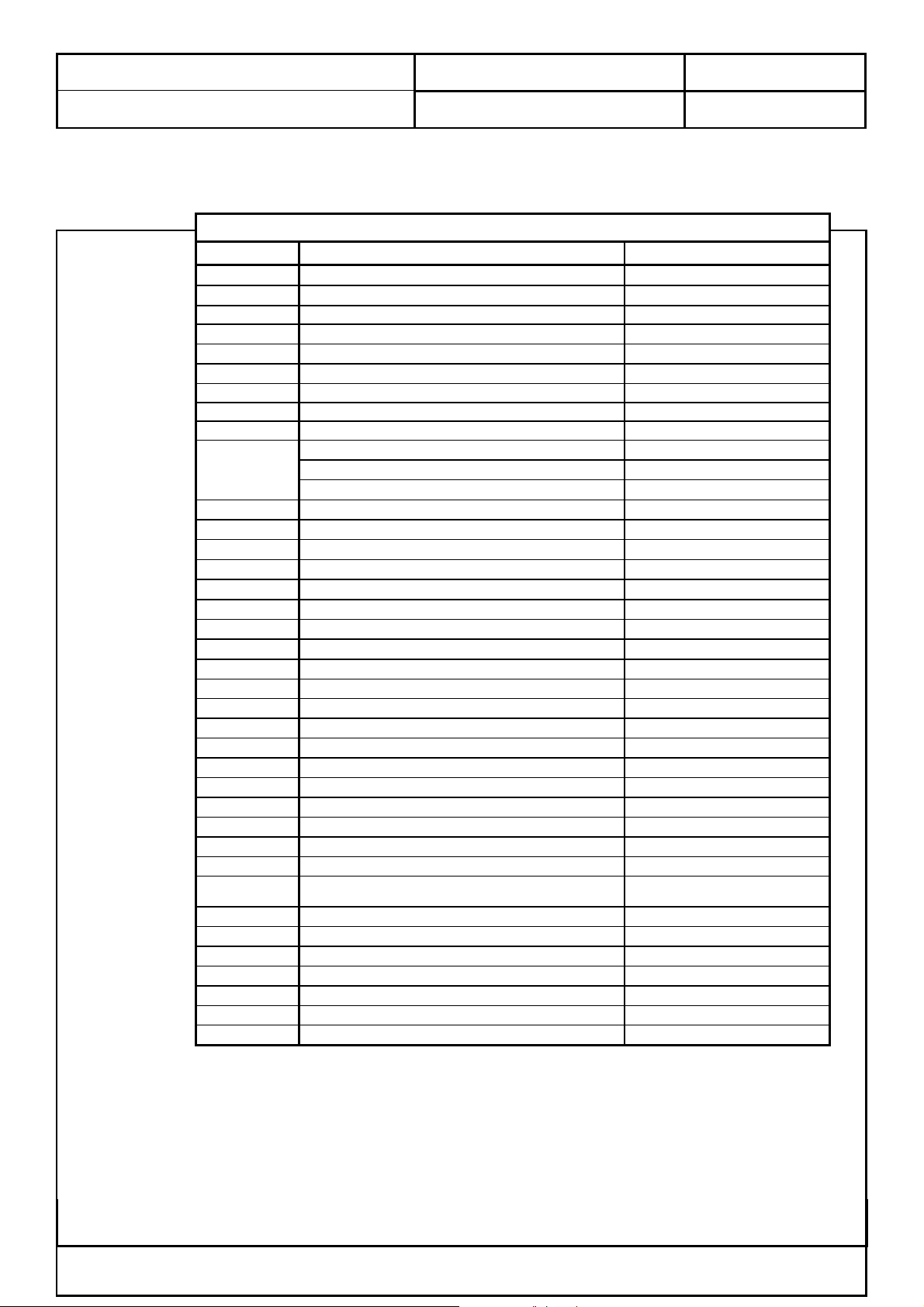
4.3.5.2 Key Functions
Key Name Key Functions PIP / Duel Picture Selected
POWER Power On / Off
INPUT TV / AV1 ( RGB ) / AV2 ( YUV ) / AV3 / VGA / DVI-D VGA / DVI-D
INFO Display channel and source
CH + Channel up
CH - Channel down
VOL + Volume up
VOL - Volume down
MUTE Mute On / Off
TV Direct Access of TV Input
STEREO Broadcast: Stereo / Mono
AUDIO
LAST Return to Previous Channel
0 - 9
SLEEP Sleep Timer Off / 30 / 60 / 90 / 120
MENU Open Menu or Enter
VIEW Scaling Mode ( Panorama / Letterbox / 4:3 / 16:9 )
PIP Duel Picture / Picture in Picture / Off
CH SCAN TV Channel Scan On / Off
FREEZE Freeze On / Off
UP ARROW
DOWN ARROW Navigate down in the OSD
LEFT ARROW Navigate left in the OSD
RIGHT ARROW Navigate right in the OSD
OK Accept the selected item in the OSD
EXIT Disable Display
F.C. Favorite channel setting
RGB Direct Access of VGA input
-- Reserved for digital receiver
RED color key Coloured button to operate the Teletext; Picture Menu
GREEN color key Coloured button to operate the Teletext; Sound Menu
YELLOW colo
key
CYAN color key Coloured button to operate the Teletext; Status Display
TEXT / C.C. Teletext mode On / Off ( Closed caption mode On / Off )
INDEX Index directly ( Teletext mode )
SUB PAGE Subpage directly ( Teletext mode )
HOLD Temporarily holds the current Teletext page ( Teletext mode )
REVEAL Displays hidden information ( Teletext mode )
GUIDE Reserved for digital receiver
BILINGUAL Broadcast: Sound 1 / Sound 2 / Sound 1+2 / Mono
MONAURAL Broadcast: Nicam / Mono
umber keys
avigate up in the OSD
Coloured button to operate the Teletext; Timer Function Menu
DOC NO.: Rev: 1.0
Remote Function for TV
This Information Is Confidential And Proprietary To Quanta And Shall Not Be Reproduced Or Otherwise Disclosed
To Anyone Other Than Quanta Employees Without Written Permission From Quanta Computer Inc.
FORM NO.:QF-00001 REV. 3C
Quanta Computer Inc.
N
N
r
Subject:
Effective Date: 2004/04/29 Page
31
of 70
Product Specification of VB1 ( EUROPE )
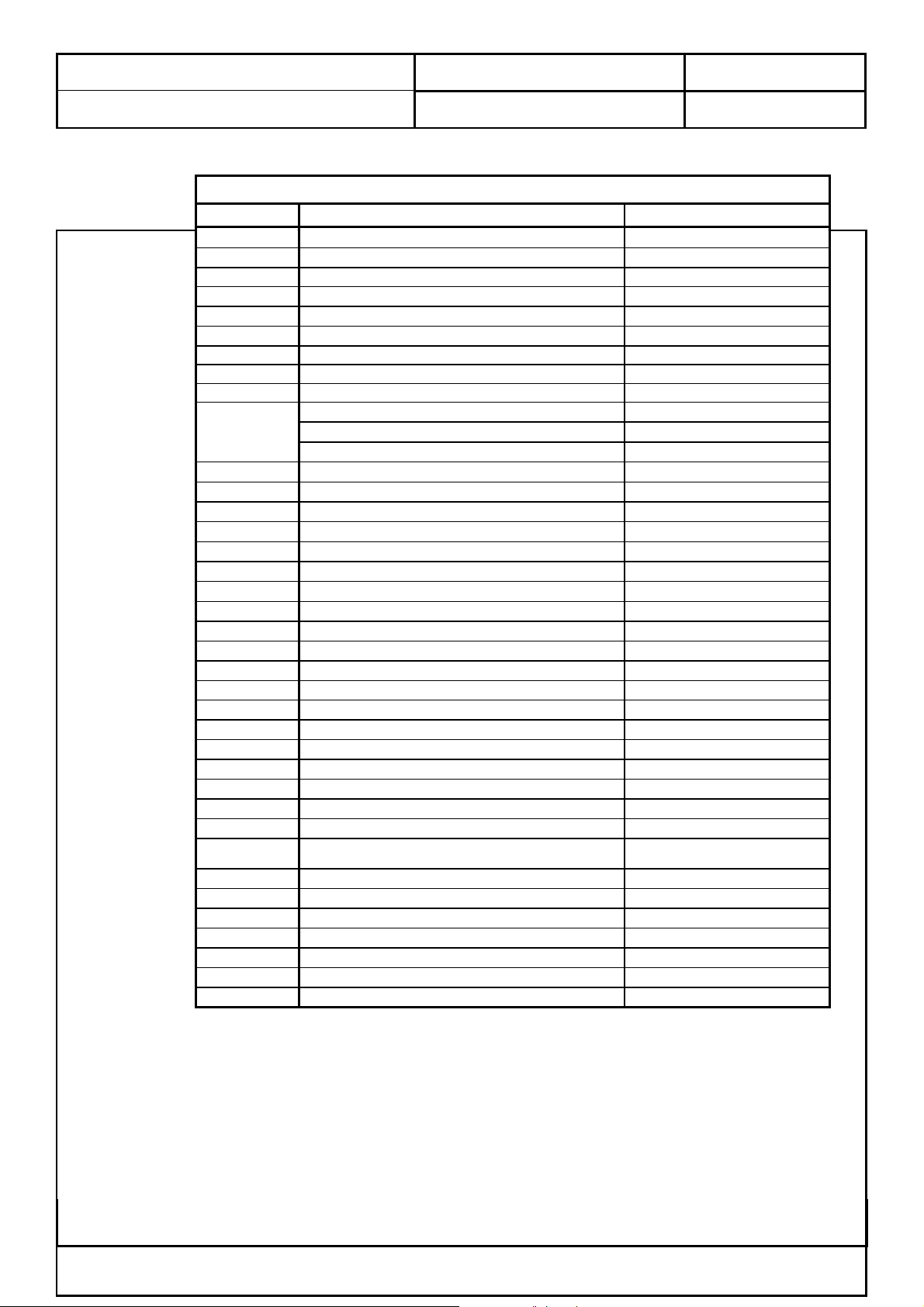
Remote Function for AV1, AV2 and AV3
Key Name Key Functions PIP / Duel Picture Selected
POWER Power On / Off
INPUT TV / AV1 ( RGB ) / AV2 ( YUV ) / AV3 / VGA / DVI-D TV / AV1 / AV2 / AV3 / VGA / DVI-D
INFO Display channel and source
CH + Channel up 2 nd Channel up key
CH - Channel down 2 nd Channel down key
VOL + Volume up
VOL - Volume down
MUTE Mute On / Off
TV Direct Access of TV Input
STEREO Broadcast: Stereo / Mono
AUDIO
LAST Return to Previous Channel
0 - 9
SLEEP Sleep Timer Off / 30 / 60 / 90 / 120
MENU Open Menu or Enter
VIEW Scaling Mode ( Panorama / Letterbox / 4:3 / 16:9 )
PIP Duel Picture / Picture in Picture / Off
CH SCAN TV Channel Scan On / Off
FREEZE Freeze On / Off
UP ARROW
DOWN ARROW Navigate down in the OSD
LEFT ARROW Navigate left in the OSD
RIGHT ARROW Navigate right in the OSD
OK Accept the selected item in the OSD
EXIT Disable Display
CC Closed caption mode On / Off
RGB Direct Access of VGA input
-- Reserved for digital receiver
RED color key Coloured button to operate the Teletext; Picture Menu
GREEN color key Coloured button to operate the Teletext; Sound Menu
YELLOW colo
key
CYAN color key Coloured button to operate the Teletext; Status Display
TEXT Teletext mode On / Off
SUB TITLE Subtitle directly ( Teletext mode )
SUB PAGE Subpage directly ( Teletext mode )
HOLD Temporarily holds the current Teletext page ( Teletext mode )
REVEAL Displays hidden information ( Teletext mode )
GUIDE Reserved for digital receiver
BILINGUAL Broadcast: Sound 1 / Sound 2 / Sound 1+2 / Mono
MONAURAL Broadcast: Nicam / Mono
umber keys To input 2 nd channel
avigate up in the OSD
Coloured button to operate the Teletext; Timer Function Menu
DOC NO.: Rev: 1.0
This Information Is Confidential And Proprietary To Quanta And Shall Not Be Reproduced Or Otherwise Disclosed
To Anyone Other Than Quanta Employees Without Written Permission From Quanta Computer Inc.
FORM NO.:QF-00001 REV. 3C

Quanta Computer Inc.
N
N
r
Subject:
Effective Date: 2004/04/29 Page
32
of 70
Product Specification of VB1 ( EUROPE )
Remote Function for VGA and DVI-D
Key Name Key Functions PIP / Duel Picture Selected
POWER Power On / Off
INPUT TV / AV1 ( RGB ) / AV2 ( YUV ) / AV3 / VGA / DVI-D TV / AV1 / AV2 / AV3 / VGA / DVI-D
INFO Display channel and source
CH + Channel up 2 nd Channel up key
CH - Channel down 2 nd Channel down key
VOL + Volume up
VOL - Volume down
MUTE Mute On / Off
TV Direct Access of TV Input
STEREO Broadcast: Stereo / Mono
AUDIO
LAST Return to Previous Channel
0 - 9
SLEEP Sleep Timer Off / 30 / 60 / 90 / 120
MENU Open Menu or Enter
VIEW Scaling Mode ( Panorama / Letterbox / 4:3 / 16:9 )
PIP Duel Picture / Picture in Picture / Off
CH SCAN TV Channel Scan On / Off
FREEZE Freeze On / Off
UP ARROW
DOWN ARROW Navigate down in the OSD
LEFT ARROW Navigate left in the OSD
RIGHT ARROW Navigate right in the OSD
OK Accept the selected item in the OSD
EXIT Disable Display
CC Closed caption mode On / Off
RGB Direct Access of VGA input
-- Reserved for digital receiver
RED color key Coloured button to operate the Teletext; Picture Menu
GREEN color key Coloured button to operate the Teletext; Sound Menu
YELLOW colo
key
CYAN color key Coloured button to operate the Teletext; Status Display
TEXT Teletext mode On / Off
SUB TITLE Subtitle directly ( Teletext mode )
SUB PAGE Subpage directly ( Teletext mode )
HOLD Temporarily holds the current Teletext page ( Teletext mode )
REVEAL Displays hidden information ( Teletext mode )
GUIDE Reserved for digital receiver
BILINGUAL Broadcast: Sound 1 / Sound 2 / Sound 1+2 / Mono
MONAURAL Broadcast: Nicam / Mono
umber keys To input 2 nd channel
avigate up in the OSD
Coloured button to operate the Teletext; Timer Function Menu
DOC NO.: Rev: 1.0
This Information Is Confidential And Proprietary To Quanta And Shall Not Be Reproduced Or Otherwise Disclosed
To Anyone Other Than Quanta Employees Without Written Permission From Quanta Computer Inc.
FORM NO.:QF-00001 REV. 3C

Quanta Computer Inc.
Subject:
Effective Date: 2004/04/29 Page
33
of 70
Product Specification of VB1 ( EUROPE )
4.3.5.3 Sound Systems
The images display examples when receiving NICAM and IGR are as follows:
Input Sound Mode Audio Key Pressed
NICA
M
Stereo ( A2 )
DOC NO.: Rev: 1.0
Monaura
l
Stereo Stereo Mono
Bilingual Sound 1 Sound 2
Sound 1+2 Mono
Stereo Stereo Mono FM
Bilingual Sound 1 Sound 2
Sound 1+2 Mono
Nicam Mono
This Information Is Confidential And Proprietary To Quanta And Shall Not Be Reproduced Or Otherwise Disclosed
To Anyone Other Than Quanta Employees Without Written Permission From Quanta Computer Inc.
FORM NO.:QF-00001 REV. 3C

Quanta Computer Inc.
Subject:
Effective Date: 2004/04/29 Page
34
of 70
Product Specification of VB1 ( EUROPE )
4.3.5.4 TeleText
TV / Teletext mode
TEXT By pressing TEXT , screen will change from TV mode to TEXT
mode and vice versa. This also applies if the mode is AV where screen will
change from AV to AV-TEXT and vice versa.
Page Selection
Pages can be selected in two ways:
a. Press or to increase or decrease the page number by one.
b. By entering the page number, using 0-9 on the remote control.
DOC NO.: Rev: 1.0
Full / Top / Bottom
Press to display special functions, followed by the Green button.
Menu Press the Green button again to expand the BOTTOM half.
Press again to return to normal ( FULL ) size.
Reveal
Press to display special functions, followed by the Red button to
Menu reveal hidden words e.g. quiz page answers. Press again to hide.
Red / Green / Yellow / Blue buttons
In fastext mode these correspond to the differently coloured subjects, In list
mode they correspond to the differently coloured page numbers
List Store
In LIST mode, after setting the list pages, press the LIST STORE
LIST STORE to save the list page. Four List pages on each program position is stored in the
NVRAM.
Hold
To hold the Teletext page when viewing multi-page information. Press
This Information Is Confidential And Proprietary To Quanta And Shall Not Be Reproduced Or Otherwise Disclosed
To Anyone Other Than Quanta Employees Without Written Permission From Quanta Computer Inc.
FORM NO.:QF-00001 REV. 3C

Quanta Computer Inc.
Subject:
Effective Date: 2004/04/29 Page
35
of 70
Product Specification of VB1 ( EUROPE )
Hold again to return to automatic page update.
Favorite Page ( F.P. )
Favorite Page (F.P.) gives direct access to the page stored in the cyan
F.P. key by the user for that program. When this key is pressed, the page number
stored in the CYAN key is requested.
Index
Index Request for PAGE 100 or INDEX PAGE
Sub Coded Page Access
When Teletext information exceeds more than one page, it may take some
time for the automatic changing of the sub pages to reach the sub page you
require. It is possible to enter your required sub page and continue watching
the normal program until the correct sub page is found.
DOC NO.: Rev: 1.0
Select the required page number using buttons 0-9.
If the top of the page indicates that sub pages are being transmitted yet the
page does not change, then the number at the top of the page is there to
indicate that he broadcaster has updated the page’s contents, there are not sub
pages.
Press Menu followed by the Blue button; T**** will be displayed at the
top right of the screen.
Enter desired sub page number before the T**** disappears. To select page 6
enter 0, 0, 0, and 6. ( If in LIST mode, a ‘T’ will appear in the current box at
the bottom ).
(Press Menu , Yellow in LIST mode ).
When the page is available, press the Yellow button to view the page.
To clear the page perform one of the following:
* Press Menu .
* Select a new page number.
* Press TEXT to return to normal TV operation.
LIST / F. TEXT
Press Menu to display special functions, followed by the Yellow button to
Setting the list page that needed.
This Information Is Confidential And Proprietary To Quanta And Shall Not Be Reproduced Or Otherwise Disclosed
To Anyone Other Than Quanta Employees Without Written Permission From Quanta Computer Inc.
FORM NO.:QF-00001 REV. 3C

Quanta Computer Inc.
Subject:
Effective Date: 2004/04/29 Page
36
of 70
Product Specification of VB1 ( EUROPE )
Menu The current list is initialized to page 100, 101, 102 and 899
DOC NO.: Rev: 1.0
This Information Is Confidential And Proprietary To Quanta And Shall Not Be Reproduced Or Otherwise Disclosed
To Anyone Other Than Quanta Employees Without Written Permission From Quanta Computer Inc.
FORM NO.:QF-00001 REV. 3C

Quanta Computer Inc.
Subject:
Effective Date: 2004/04/29 Page
37
of 70
Product Specification of VB1 ( EUROPE )
4.3.5.5 View Mode
Panorama : This mode is useful for 1.78:1 DVDs.
When viewing 1.85:1 DVDs, stretch mode will still show very thin
black bands at the top and bottom of the screen.
16 : 9 : Will display the picture at its maximum size but with slight stretching.
4 : 3 : Will display a 4 : 3 picture at its standard 4 : 3 size without any
stretching. Black stripes will be visible down the left and right sides
of the picture.
DOC NO.: Rev: 1.0
LetterBox: This is useful for simulated 16:9 formate from DVD player. Select
this view mode to have over screen.
There shall have view mode information shown on top-right corner for around 10 seconds while
change view mode from remote controller.
This Information Is Confidential And Proprietary To Quanta And Shall Not Be Reproduced Or Otherwise Disclosed
To Anyone Other Than Quanta Employees Without Written Permission From Quanta Computer Inc.
FORM NO.:QF-00001 REV. 3C

Quanta Computer Inc.
Subject:
Effective Date: 2004/04/29 Page
38
of 70
Product Specification of VB1 ( EUROPE )
4.3.5.6 Multi Picture
Press Source key to Select
Input
Duel Picture
Step 1: Press PIP key once to display duel picture
as left side.
Step 2: Press Source key to or input channel number
The screen would be as right side.
for 2
nd
media.
Picture in Picture
Step 1: Press PIP key twice to display picture in picture
as left side.
Step 2: Press Source key or input channel number
for 2
nd
media. Please refer to right figure.
Channel Scan
Press Scan key once in TV or CATV mode to active
channel scan. This TV would start to scan channels from
original channel.
Press Scan key once again to stop channel scan
and return to main source.
DOC NO.: Rev: 1.0
Freeze
Press Freeze key to freeze screen.
Press Freeze key again to release it.
As left figure, froze screen would be on left side
and remain lived screen on right side.
There are two source groups, group 1 including TV, AV1, AV2, AV3 and YCbCr, group 2
including YPbPr, VGA and DVI-D. Multi picture function is available for different group source
only.
Ex. TV could have picture and picture to YPbPr, VGA or DVI-D.
TV could not have PIP function to AV1, AV2, AV3 and YCbCr
This Information Is Confidential And Proprietary To Quanta And Shall Not Be Reproduced Or Otherwise Disclosed
To Anyone Other Than Quanta Employees Without Written Permission From Quanta Computer Inc.
FORM NO.:QF-00001 REV. 3C

Quanta Computer Inc.
Subject:
Effective Date: 2004/04/29 Page
39
of 70
Product Specification of VB1 ( EUROPE )
DOC NO.: Rev: 1.0
4.3.6 OSD Menu Abstract Structure
4.3.6.1 OSD Menu for EUROPE
TV OSD Menu
1st Sub Menu 2nd Sub Menu 3rd Sub Menu
Picture Menu Contrast
Brightness
Colour
Tint
Sharpness
Phase
Color Temp Cold / Standard / Warm
Audio Menu Surround Bypass / TruBass / 3D-STEREO / WOW
Treble
Bass
Balance
Auto Search Country
Colour System PAL / SECAM
Setup Menu
Start Search
Maunal Search
Colour System PAL / SECAM
Sound System B/G / D/K / I / L
Status Active / Inactive
Sort
Auto Picture 4:3 / Panorama
Options Menu
For This Program No/ Yes
Factory Preset
Sound System B/G / D/K / I / L
Store Progr. From
Channel 〔 XX 〕
Frequency〔 XXX.XXMHz 〕
Name 〔 〕
Sleep [ Off ]
Auto Power Off 〔 Off 〕
Child Lock
Language [ English ]
Serial Number [ xxxxxxx ]
Erase No / Yes
Off / 30 / 60 / 90 / 120
Off / On
Please Input Password 〔 ???? 〕
English / German / French / Spanish /
Italian / Swedish / Dutch
Are you sure [ No ]
Australia / France / Germany / Italy / Netherlands / Spain / Swiss /
UK / Others
For All Programmes No/ Yes
Change Password 〔 ???? 〕
No / Yes
TV Systems Used in Various Countries
Country
Colour
System
Sound System Country
Austria PAL B/G Italy PAL B/G
Belgium PAL B/G Netherlands PAL B/G
Czech Republic PAL D/K Poland PAL D/K
France SECAM L Slovenia PAL D/K
UK PAL I Spain PAL B/G
Germany PAL B/G Switzerland PAL B/G
Hungary SECAM D/K
This Information Is Confidential And Proprietary To Quanta And Shall Not Be Reproduced Or Otherwise Disclosed
To Anyone Other Than Quanta Employees Without Written Permission From Quanta Computer Inc.
Colour
System
Sound System
FORM NO.:QF-00001 REV. 3C

Quanta Computer Inc.
Subject:
Effective Date: 2004/04/29 Page
40
of 70
Product Specification of VB1 ( EUROPE )
DOC NO.: Rev: 1.0
AV 1, AV 2 and AV 3 OSD Menu
1st Sub Menu 2nd Sub Menu 3rd Sub Menu
Picture Menu Contrast
Brightness
Colour
Tint
Sharpness
Phase
Audio Menu Surround Bypass / TruBass / 3D-STEREO / WOW
Treble
Bass
Balance
AV 1 CVBS / Y/C / RGB
AV Connections AV 2 CVBS / Y/C / YUV
AV 3
Auto Picture 4:3 / Panorama
Options Menu
For This Program No/ Yes
Factory Preset
Color Temp 〔 Standard 〕
Sleep [ Off ]
Auto Power Off 〔 Off 〕
Child Lock
Language [ English ]
Serial Number [ xxxxxxx ]
Cold / Standard / Warm
AV 3 In-Out [ In ]
Off / 30 / 60 / 90 / 120
Off / On
Please Input Password 〔 ???? 〕
English / German / French / Spanish /
Italian / Swedish / Dutch
Are you sure [ No ]
In / Out
For All Programmes No/ Yes
Change Password 〔 ???? 〕
No / Yes
This Information Is Confidential And Proprietary To Quanta And Shall Not Be Reproduced Or Otherwise Disclosed
To Anyone Other Than Quanta Employees Without Written Permission From Quanta Computer Inc.
FORM NO.:QF-00001 REV. 3C

Quanta Computer Inc.
/
/
N
Subject:
Effective Date: 2004/04/29 Page
41
of 70
Product Specification of VB1 ( EUROPE )
VGA OSD Menu
1st Sub Menu 2nd Sub Menu 3rd Sub Menu 4th Sub Menu
Picture Menu Contrast
Brightness
H-Position
V-Position
Clock
Phase
Auto Adjust
Audio Menu
Treble
Bass
Balance
Colour Menu
Options Menu
Factory Preset
Surround 〔 Off 〕
Colour Temp. [ Standard ]
Language [ English ]
Serial Number [ xxxxxxx ]
DOC NO.: Rev: 1.0
Off / Simulated / Stereo / Mono
Cold / Standard / Warm
English / German / French / Spanish
Italian / Swedish / Dutch
Are you sure [ No ]
No / Yes
DVI-D OSD Menu
1st Sub Menu 2nd Sub Menu 3rd Sub Menu 4th Sub Menu
Picture Menu Contrast
Brightness
Audio Menu
Treble
Bass
Balance
Colour Menu
Options Menu
Factory Preset
Surround 〔 Off 〕
Colour Temp. [ Standard ]
Language [ English ]
Serial Number [ xxxxxxx ]
Off / Simulated / Stereo / Mono
Cold / Standard / Warm
English / German / French / Spanish
Italian / Swedish / Dutch
Are you sure [ No ]
o / Yes
This Information Is Confidential And Proprietary To Quanta And Shall Not Be Reproduced Or Otherwise Disclosed
To Anyone Other Than Quanta Employees Without Written Permission From Quanta Computer Inc.
FORM NO.:QF-00001 REV. 3C

Quanta Computer Inc.
Subject:
Effective Date: 2004/04/29 Page
42
of 70
Product Specification of VB1 ( EUROPE )
4.3.7 OSD format
The five icons shall be put on
the left of relative text on
OSD
OSD Format for TV
Main Menu
DOC NO.: Rev: 1.0
Picture Menu Setup Menu Color Menu
Audio Menu Options Menu
Step 1: Press the Menu key to display the OSD. Press Exit key to close OSD.
Step 2: Moving cursor to Picture Menu by pressing ▲ or ▼ keys.
Step 3: Press the OK key to enter Picture menu.
Picture Menu…..Contrast
Step 1: Moving cursor to Contrast icon by pressing▲ or ▼ keys.
Step 2: Press the or to set Contrast value.
( Press the Exit key again to return to Main Menu. )
Picture Menu…..Brightness
Step 1: Moving cursor to Brightness icon by pressing ▲ or ▼ keys.
Step 2: Press the or to set Brightness value.
( Press the Exit key again to return to Main Menu. )
Picture Menu…..Color
Step 1: Moving cursor to Color icon by pressing ▲ or ▼ keys.
Step 2: Press the or to set Color value.
( Press the Exit key again to return to Main Menu. )
Picture Menu…..Tint
Step 1: Moving cursor to Tint icon by pressing ▲ or ▼ keys.
Step 2: Press the or to set Tint value.
( Press the Exit key again to return to Main Menu. )
Tint adjustment is only available while input signal is NTSC.
This Information Is Confidential And Proprietary To Quanta And Shall Not Be Reproduced Or Otherwise Disclosed
To Anyone Other Than Quanta Employees Without Written Permission From Quanta Computer Inc.
FORM NO.:QF-00001 REV. 3C

Quanta Computer Inc.
Subject:
Effective Date: 2004/04/29 Page
43
of 70
Product Specification of VB1 ( EUROPE )
Picture Menu…..Sharpness
Picture Menu…..Color Temperature
DOC NO.: Rev: 1.0
Step 1: Moving cursor to Sharpness icon by pressing ▲ or ▼ keys.
Step 2: Press the or to set Sharpness value.
( Press the Exit key again to return to Main Menu. )
Step 1: Moving cursor to Color Temp icon by pressing ▲ or ▼ keys.
Step 2: Press the or to select color temperature.
( Press the Exit key again to return to Main Menu. )
There are three different color temperature which are Standard, Warm and
Cold for selecting.
Main Menu
Step 1: Press the Menu key to display the OSD. Press Exit key to close OSD.
Step 2: Moving cursor to Audio Menu by pressing ▲ or ▼ keys.
Step 3: Press the or to enter Audio menu.
Audio Menu.....Treble
Step 1: Moving cursor to Treble icon by pressing ▲ or ▼ keys.
Step 2: Press the or to set Treble value.
( Press the Exit key to return to Main Menu. )
This Information Is Confidential And Proprietary To Quanta And Shall Not Be Reproduced Or Otherwise Disclosed
To Anyone Other Than Quanta Employees Without Written Permission From Quanta Computer Inc.
FORM NO.:QF-00001 REV. 3C

Quanta Computer Inc.
Subject:
Effective Date: 2004/04/29 Page
44
of 70
Product Specification of VB1 ( EUROPE )
Audio Menu…..Bass
Audio Menu.....Balance
DOC NO.: Rev: 1.0
Step 1: Moving cursor to Bass icon by pressing ▲ or ▼ keys.
Step 2: Press the or to set Bass value.
( Press the Exit key to return to Main Menu. )
Step 1: Moving cursor to Balance icon by pressing ▲ or ▼ keys.
Step 2: Press the or to set Balance value.
( Press the Exit key to return to Main Menu. )
Main Menu
Step 1: Press the Menu key to display the OSD. Press Exit key to close OSD.
Step 2: Moving cursor to Setup Menu by pressing ▲ or ▼ keys.
Step 3: Press the OK to enter Setup menu.
Setup Menu…..Auto Search
Step 1: Moving cursor to Auto Search icon by pressing ▲ or ▼ keys.
Step 2: Press the OK to enter Auto Search menu.
( Press the Exit key to return to Main Menu. )
Auto Search Menu…..Country
Step 1: Moving cursor to Country icon by pressing ▲ or ▼ keys.
Step 2: Press the or to select Country settings.
There are 14 different Countries which are Denmark, Finland, France,
Germany, Iceland, Ireland, Italy, Netherlands, Norway, Spain, Sweden,
Swiss, UK, and Others.
Color System and Sound System will be available for selection when
Country is set to Others.
( Press the Exit key again to return to Setup Menu. )
Auto Search Menu…..Store Progr. From
Step 1: Moving cursor to Store Progr. From icon by pressing ▲ or ▼ keys.
Step 2: Press the or to store program from the selected channel
number.
( Press the Exit key again to return to Setup Menu. )
This Information Is Confidential And Proprietary To Quanta And Shall Not Be Reproduced Or Otherwise Disclosed
To Anyone Other Than Quanta Employees Without Written Permission From Quanta Computer Inc.
FORM NO.:QF-00001 REV. 3C

Quanta Computer Inc.
Subject:
Effective Date: 2004/04/29 Page
45
of 70
Product Specification of VB1 ( EUROPE )
DOC NO.: Rev: 1.0
Auto Search Menu…..Start Search
Step 1: Moving cursor to Start Search icon by pressing ▲ or ▼ keys.
Step 2: Press the or to start auto search.
( Press the Exit key again to return to Setup Menu. )
Setup Menu…..Manual Search
Step 1: Moving cursor to Manual Search icon by pressing ▲ or ▼ keys.
Step 2: Press the OK to enter Manual search menu.
( Press the Exit key to return to Main Menu. )
Manual Search Menu…..Channel
Step 1: Moving cursor to Channel icon by pressing ▲ or ▼ keys.
Step 2: Press the or to select the channel number to do manual
search.
( Press the Exit key to return to Setup Menu. )
Manual Search Menu…..Frequency
Step 1: Moving cursor to Frequency icon by pressing ▲ or ▼ keys.
Step 2: Press the OK button to start entering channel frequency.
Step 3: Press the OK button again after frequency has been entered.
( Press the Exit key to return to Setup Menu. )
Manual Search Menu…..Name
Step 1: Moving cursor to Name icon by pressing ▲ or ▼ keys.
Step 2: Press the OK button to start entering channel name.
Step 3: Press the ▲ or ▼ keys to select different character.
Step 4: Press the or to select previous or next letter to modify.
Step 5: Press the OK button again after channel name has been entered.
( Press the Exit key to return to Setup Menu. )
Manual Search Menu…..Colour System
Step 1: Moving cursor to Colour System icon by pressing ▲ or ▼ keys.
Step 2: Press the or to select Colour System
There are two different Colour Systems which are PAL and SECAM.
( Press the Exit key to return to Setup Menu. )
This Information Is Confidential And Proprietary To Quanta And Shall Not Be Reproduced Or Otherwise Disclosed
To Anyone Other Than Quanta Employees Without Written Permission From Quanta Computer Inc.
FORM NO.:QF-00001 REV. 3C

Quanta Computer Inc.
Subject:
Effective Date: 2004/04/29 Page
46
of 70
Product Specification of VB1 ( EUROPE )
DOC NO.: Rev: 1.0
Manual Search Menu…..Sound System
Step 1: Moving cursor to Sound System icon by pressing ▲ or ▼ keys.
Step 2: Press the or to select Sound System
There are four different Sound Systems which are B/G, D/K, I and L.
( Press the Exit key to return to Setup Menu. )
Manual Search Menu…..Status
Step 1: Moving cursor to Status icon by pressing ▲ or ▼ keys.
Step 2: Press the or to select Channel Status between Active and
Inactive.
If the Status is set to Inactive, the channel will be skipped when user press
the channel up/down key.
( Press the Exit key to return to Setup Menu. )
Manual Search Menu…..Erase
Step 1: Moving cursor to Erase icon by pressing ▲ or ▼ keys.
Step 2: Press the or to erase the current settings of this channel.
( Press the Exit key to return to Setup Menu. )
Setup Menu…..Sort
Step 1: Moving cursor to Sort icon by pressing ▲ or ▼ keys.
Step 2: Press the OK to enter Sort menu.
( Press the Exit key to return to Main Menu. )
Sort
Step 1: Moving cursor to the channel number to be relocated and press OK
to select.
Step 2: Moving cursor to move the channel arround.
Step 3: Press OK again to re-position the channel.
( Press the Exit key to return to Setup Menu. )
Main Menu
Step 1: Press the Menu key to display the OSD. Press Exit key again to
close OSD.
Step 2: Moving cursor to Options Menu by pressing ▲ or ▼ keys.
Step 3: Press the OK to enter Options menu.
This Information Is Confidential And Proprietary To Quanta And Shall Not Be Reproduced Or Otherwise Disclosed
To Anyone Other Than Quanta Employees Without Written Permission From Quanta Computer Inc.
FORM NO.:QF-00001 REV. 3C

Quanta Computer Inc.
Subject:
Effective Date: 2004/04/29 Page
47
of 70
Product Specification of VB1 ( EUROPE )
DOC NO.: Rev: 1.0
Options Menu…..Auto Picture
Step 1: Moving cursor to Auto Picture icon by pressing ▲ or ▼ keys.
Step 2: Press the or to select the Auto Picture setting.
There are two different view modes for selection which are Panorama and
4:3.
When input signal is 4:3 format, the view mode will be set according to Auto
Picture setting.
( Press the Exit key to return to Main Menu. )
Options Menu…..Sleep
Step 1: Moving cursor to Sleep icon by pressing ▲ or ▼ keys.
Step 2: Press the or to set time to turn TV off.
( Press the Exit key to return to Main Menu. )
There are 5 different status for selection which are OFF, 30, 60, 90 and
120 minutes.
Options Menu…..Auto Power Off
Step 1: Moving cursor to Auto Power Off icon by pressing ▲ or ▼ keys.
Step 2: Press the or to set Auto Power Off setting.
( Press the Exit key to return to Main Menu. )
When Auto Power Off is ON, TV will be turned off automatically after there
is no signal for 5 minutes.
Options Menu…..Child Lock
Step 1: Moving cursor to Child Lock icon by pressing ▲ or ▼ keys.
Step 2: Press the OK to enter Child Lock menu.
( Press the Exit key to return to Main Menu. )
Child Lock….. Enter Password
Step 1: Enter 4 digits by pressing number keys before entering Child Lock
Menu. ( the initial number is 0000 )
( Press the Exit key to return to Options Menu. )
Input Password would be request again if select a channel that has been
blocked.
Child Lock Menu…..For All Programs
Step 1: Moving cursor to For All Programs icon by pressing ▲ or ▼ keys.
Step 2: Press the or to lock all channels.
( Press the Exit key to return to Options Menu. )
This Information Is Confidential And Proprietary To Quanta And Shall Not Be Reproduced Or Otherwise Disclosed
To Anyone Other Than Quanta Employees Without Written Permission From Quanta Computer Inc.
FORM NO.:QF-00001 REV. 3C

Quanta Computer Inc.
Subject:
Effective Date: 2004/04/29 Page
48
of 70
Product Specification of VB1 ( EUROPE )
DOC NO.: Rev: 1.0
Child Lock Menu…..For This Program
Step 1: Moving cursor to For This Program icon by pressing ▲ or ▼ keys.
Step 2: Press the or to lock this channels.
( Press the Exit key to return to Options Menu. )
Child Lock Menu…..Change Password
Step 1: Moving cursor to Change Password icon by pressing ▲ or ▼ keys.
Step 2: Press the OK to proceed changing Password.
Step 3: Enter 4 numbers to be new Password by pressing number keys.
Step 4: Enter 4 numbers again to confirm new Password.
( Press the Exit key to return to Parental Controls Menu. )
Options Menu.....Language
Step 1: Moving cursor to Language icon by pressing ▲ or ▼ keys.
Step 2: Press the or to set OSD language.
( Press the Exit key to return to Main Menu. )
Options Menu…..Serial Number
Step 1: Moving cursor to Serial Number icon by pressing ▲ or ▼ keys to
show serial number of TV set.
The or would be no function available for Serial Number.
( Press the Exit key to return to Main Menu. )
Options Menu…..Factory Preset
Step 1: Moving cursor to Factory Preset icon by pressing ▲ or ▼ keys.
Step 2: Press the OK to reset all setting back to factory presetting.
( Press the Exit key to return to Main Menu. )
Options Menu…..Factory Preset
Step 1: Moving cursor to select Yes by pressing ▲ or ▼ keys.
Step 2: Press the OK to reset all setting back to factory presetting.
( Press the Exit key to return to previous Menu. )
This Information Is Confidential And Proprietary To Quanta And Shall Not Be Reproduced Or Otherwise Disclosed
To Anyone Other Than Quanta Employees Without Written Permission From Quanta Computer Inc.
FORM NO.:QF-00001 REV. 3C

Quanta Computer Inc.
Subject:
Effective Date: 2004/04/29 Page
49
of 70
Product Specification of VB1 ( EUROPE )
OSD Format for AV1, AV2 and AV3
The Picture, Audio, and Options Menu of AV1, AV2 and AV3 are the same as TV.
DOC NO.: Rev: 1.0
Main Menu….AV Connections
Step 1: Press the Menu key to display the OSD. Press Exit key again to
close OSD.
Step 2: Moving cursor to AV Connections menu by pressing ▲ or ▼ keys.
Step 3: Press the OK to enter AV Connections menu.
AV Connections Menu….AV1
Step 1: Moving cursor to AV1 icon by pressing ▲ or ▼ keys.
Step 2: Press the or to set AV1 input signal type.
There are 3 different types for selection which are CVBS, Y/C and
RGB.
( Press the Exit key to return to Main Menu. )
AV Connections Menu….AV2
Step 1: Moving cursor to AV2 icon by pressing ▲ or ▼ keys.
Step 2: Press the or to set AV2 input signal type.
There are 3 different types for selection which are CVBS, Y/C and
YUV.
( Press the Exit key to return to Main Menu. )
AV Connections Menu…..AV3
Step 1: Moving cursor to AV3 icon by pressing ▲ or ▼ keys.
Step 2: Press the or to set AV3 to be input or output.
( Press the Exit key to return to Main Menu. )
This Information Is Confidential And Proprietary To Quanta And Shall Not Be Reproduced Or Otherwise Disclosed
To Anyone Other Than Quanta Employees Without Written Permission From Quanta Computer Inc.
FORM NO.:QF-00001 REV. 3C

Quanta Computer Inc.
Subject:
Effective Date: 2004/04/29 Page
50
of 70
Product Specification of VB1 ( EUROPE )
DOC NO.: Rev: 1.0
Clear Password
Please press and hold both of CH and Vol + on TV set
simultaneously until the message " Enter New Password " appears if forget
current Password.
Then input new Password.
Blocked channels…….Enter Password
While selected media is blocked channel, the OSD shall show message as
left side.
Input Password to cancel Child Lock temporarily.
The channel block would be activated again while power off.
This Information Is Confidential And Proprietary To Quanta And Shall Not Be Reproduced Or Otherwise Disclosed
To Anyone Other Than Quanta Employees Without Written Permission From Quanta Computer Inc.
FORM NO.:QF-00001 REV. 3C

Quanta Computer Inc.
Subject:
Effective Date: 2004/04/29 Page
51
of 70
Product Specification of VB1 ( EUROPE )
OSD Format for VGA
DOC NO.: Rev: 1.0
Main Menu
Step 1: Press the Menu key to display the OSD. Press Exit key to close OSD.
Step 2: Moving cursor to Picture Menu by pressing ▲ or ▼ keys.
Step 3: Press the OK to enter Picture menu.
Picture Menu…….Contrast
Step 1: Moving cursor to Contrast icon by pressing ▲ or ▼ keys.
Step 2: Press the or to set Contrast value.
( Press the Exit key to return to Main Menu. )
Picture Menu…….Brightness
Step 1: Moving cursor to Brightness icon by pressing ▲ or ▼ keys.
Step 2: Press the or to set Brightness value.
( Press the Exit key to return to Main Menu. )
Picture Menu…..H-Position Picture Menu…..V-Position Picture Menu…..Clock
Picture Menu…..Phase Picture Menu…..Auto Adjust
This Information Is Confidential And Proprietary To Quanta And Shall Not Be Reproduced Or Otherwise Disclosed
To Anyone Other Than Quanta Employees Without Written Permission From Quanta Computer Inc.
FORM NO.:QF-00001 REV. 3C

Quanta Computer Inc.
Subject:
Effective Date: 2004/04/29 Page
52
of 70
Product Specification of VB1 ( EUROPE )
DOC NO.: Rev: 1.0
Main Menu
Step 1: Press the Menu key to display the OSD. Press Exit key to close OSD.
Step 2: Moving cursor to Audio Menu by pressing ▲ or ▼ keys.
Step 3: Press the OK to enter Audio menu.
Audio Menu would be same as TV.
Main Menu
Step 1: Press the Menu key to display the OSD. Press Exit key to close OSD.
Step 2: Moving cursor to Color Menu by pressing ▲ or ▼ keys.
Step 3: Press the OK to enter Color menu.
Color Menu
Step 1: Moving cursor to select color temperature by pressing or
keys.
Step 2: Press the Exit key to active selected color temperature and return to
Main Menu.
This Information Is Confidential And Proprietary To Quanta And Shall Not Be Reproduced Or Otherwise Disclosed
To Anyone Other Than Quanta Employees Without Written Permission From Quanta Computer Inc.
FORM NO.:QF-00001 REV. 3C

Quanta Computer Inc.
Subject:
Effective Date: 2004/04/29 Page
53
of 70
Product Specification of VB1 ( EUROPE )
DOC NO.: Rev: 1.0
Main Menu
Step 1: Press the Menu key to display the OSD. Press Exit key to
close OSD.
Step 2: Moving cursor to Option Menu by pressing ▲ or ▼ keys.
Step 3: Press the OK to enter Options menu.
Options Menu…….Factory Preset
Step 1: Moving cursor to select icon by pressing ▲ or ▼ keys.
Step 2: Press the or to set status for each function.
( Press the Exit key to return to Main Menu. )
The functions of Options Menu would be same as TV. Pls. refer to TV.
This Information Is Confidential And Proprietary To Quanta And Shall Not Be Reproduced Or Otherwise Disclosed
To Anyone Other Than Quanta Employees Without Written Permission From Quanta Computer Inc.
FORM NO.:QF-00001 REV. 3C

Quanta Computer Inc.
Subject:
Effective Date: 2004/04/29 Page
54
of 70
Product Specification of VB1 ( EUROPE )
4.3.8 On Screen Message
This section illustrates about the system on screen message.
Volume
Volume
||||||||||||||||……… 50
Channel
26 BBC1
DOC NO.: Rev: 1.0
Pressing Vol - or Vol + keys directly, there will be a volume control
message shown at bottom side, then press Vol + key to increase the
volume or press Vol - key to decrease the volume.
Keep pressing the control keys, the value will be updated.
The display would be turned off after 10 seconds later if there is no volume
key pressed.
Pressing CH or CH keys directly while there is no OSD Menu on the
screen, there will be a Channel status shown at the right up corner of the
screen, then press CH key to increase the Channel or press CH key to
decrease the Channel.
Keep pressing the control keys, the Channel will be increased or decreased
cyclically.
The display would be turned off after 10 seconds later if there is no channel
key pressed.
Input
TV AV1 AV2
DVI VGA AV3
Last
26 BBC1
Pressing Input key directly to select different signal source, the message will
be shown at the right up corner of the screen.
Keep pressing the input key, the signal source will be switch cyclically.
While source is TV, channel shall be displayed as follows
26 BBC1
The display would be turned off after 10 seconds later if Source key is not
pressed.
While Last key is pressed, this TV shall switch back to previously channel
and show channel message on screen.
26 BBC1
The channel message shall disappear automatically 10 seconds later.
This Information Is Confidential And Proprietary To Quanta And Shall Not Be Reproduced Or Otherwise Disclosed
To Anyone Other Than Quanta Employees Without Written Permission From Quanta Computer Inc.
FORM NO.:QF-00001 REV. 3C

Quanta Computer Inc.
Subject:
Effective Date: 2004/04/29 Page
55
of 70
Product Specification of VB1 ( EUROPE )
Info
Video Source and
Channel
26 BBC1
Mute
Mute
DOC NO.: Rev: 1.0
While Info key is pressed, the status of system shall be shown on the right up
corner of the screen. The system status include:
Video Source: TV, AV1, S1, RGB, AV2, S2, YCbCr,
YPbPr, AV3, VGA or DVI-D
Channel: Channel Number Name
For example:
26 BBC1
AV2
The display would be turned off once Info key is pressed again.
While Mute key is pressed to active mute function, the Mute message shall
be shown on right down corner.
Mute would be automatically turned off when any of following buttons are
pressed: Power, Vol - , Vol + , Sound or Mute again.
Sound
Sound 1
Sleep
Sleep OFF
While press Sound key to select sound system, the sound system shall be
shown on right down corner.
The display would be turned off after 10 seconds later if Sound key is not
pressed again.
While Sleep key is pressed, the message shall be shown on left up corner.
Keep pressing the Sleep key, the status will be switch cyclically as follows.
Sleep OFF Sleep 30 Sleep 60
NO Display Sleep 120 Sleep 90
The message would be turned off after 10 seconds later if Sleep key is not
pressed and status is maintaining on Sleep OFF.
The sleep function would be activated 10 seconds later if Sleep key is not
pressed again and status is maintaining on Sleep 30, 60, 90 or 120.
Once sleep function is activated, time left would be shown as follow.
Sleep 29 Minute No Display
Once sleep function is activated, user could press Sleep key again to stop
sleep function.
This Information Is Confidential And Proprietary To Quanta And Shall Not Be Reproduced Or Otherwise Disclosed
To Anyone Other Than Quanta Employees Without Written Permission From Quanta Computer Inc.
FORM NO.:QF-00001 REV. 3C

Quanta Computer Inc.
Subject:
Effective Date: 2004/04/29 Page
56
of 70
Product Specification of VB1 ( EUROPE )
DOC NO.: Rev: 1.0
4.3.9 OSD Translations:
English
English English English English
Français Français Français Français
Español Español Español Español
中文繁體 中文繁體 中文繁體 中文繁體
Main Menu
Picture Menu
Audio Menu
Setup Menu
Options Menu
Return
Move
Setting
Closed Caption
Parental Controls
Treble
Bass
Balance
Password
Channel Block has been activated
Manual Search
Select Channel
Add Channel
Erase Channel
Blue Screen
Sleep
AV2/S2 AV2/S2 AV2/S2 AV2/S2
AV2 AV2 AV2 AV2
S2 S2 S2 S2
AV3 in-out AV3 in-out AV3 En-Dehors AV3 En-Fuera
Language
Power Save
Serial Number
Factory Preset
IN
OUT
Standard
OFF
ON
Status
MPAA MPAA MPAA MPAA
TV Guidelines TV Guidelines TV Guidelines TV Guidelines
Can. English TV Can. English TV Can. English TV Can. English TV
Can. French TV Can. French TV Can. French TV Can. French TV
Change Password
Contrast
Color
Tint
Sharpness
Color Temp
This Information Is Confidential And Proprietary To Quanta And Shall Not Be Reproduced Or Otherwise Disclosed
To Anyone Other Than Quanta Employees Without Written Permission From Quanta Computer Inc.
繁體中文
主選單
畫面選單
音效選單
設定選單
操作選單
返回
移動
設定
閉路字幕
鎖定頻道
高音
低音
平衡
密碼
頻道鎖定
手動搜尋
選擇頻道
增加頻道
刪除頻道
藍色螢幕
睡眠
30 30 30 30
60 60 60 60
90 90 90 90
120 120 120 120
語言
省電
出廠序號
出廠設定
輸入
輸出
標準色溫
關
開
狀態
更改密碼
對比
色彩
色調
銳利
色溫
French Spanish
Menu Principal Principal Menú
Menu Image Imagen Menú
Menu Audio Audio Menú
Menu Setup Arreglo Menú
Menu Options Opción Menú
Retour Retorno
Monter Jugada
Réglage Control
Closed Caption Closed Caption
Parental Réglage Paternal Controls
Triple De triple
Basse
Balance Balance
Mot de passe La contraseña
Diriger le Bloc a été activé El Bloque del canal se ha activado
Recherche manuelle
Choisir la Chaîne
Ajouter la Chaîne Agregue el Canal
Effacer la Chaîne Borre el Canal
Ecran bleu el Fondo Azul
Sommeil El sueño
Langue El idioma
Sauf énergie Salvar Poder
No. Série N" de Serie
Rappeler Restaurar
En En
Dehors Fuera
Standard Estándar
Arrêt Desactivado
Marche Activado
Statut Estatus
Changer le Mot de passe Cambie la Contraseña
Contraste Contraste
Couleur Color
Teinte Tono
Netteté Nitidez
Couleur Temp Color Temp
Bajo
La Búsqueda manual
El Canal selecto
FORM NO.:QF-00001 REV. 3C

Quanta Computer Inc.
N
N
N
N
Subject:
Effective Date: 2004/04/29 Page
57
of 70
Product Specification of VB1 ( EUROPE )
DOC NO.: Rev: 1.0
Brightness
C1 C1 C1 C1
C2 C2 C2 C2
C3 C3 C3 C3
C4 C4 C4 C4
T1 T1 T1 T1
T2 T2 T2 T2
T3 T3 T3 T3
T4 T4 T4 T4
Auto Search
R R R R
G G G G
B B B B
H-Position
V-Position
Clock Horloge Ciclo
Phase Fase Fasi
G G G G
PG PG PG PG
PG-13 PG-13 PG-13 PG-13
R R R R
C-17
X X X X
Unblock
Block
TV-Y TV-Y TV-Y TV-Y
TV-Y7 TV-Y7 TV-Y7 TV-Y7
TV-G TV-G TV-G TV-G
TV--PG TV--PG TV--PG TV--PG
TV-14 TV-14 TV-14 TV-14
TV-MA TV-MA TV-MA TV-MA
FV FV FV FV
V V V V
S S S S
L L L L
D D D D
TV Parental Guidelines TV Parental Guidelines TV Parental Guidelines TV Parental Guidelines
E E E E
C C C C
C8- C8- C8- C8G G G G
PG PG PG PG
14+ 14+ 14+ 14+
18+ 18+ 18+ 18+
Canadian English Ratings
G G G G
8 ans + 8 ans + 8 ans + 8 ans +
13 ans + 13 ans + 13 ans + 13 ans +
16 ans + 16 ans + 16 ans + 16 ans +
18 ans + 18 ans + 18 ans + 18 ans +
Canadian French Ratings
Stereo
Mono
Main
SAP
Dual
亮度
自動搜尋
水平相位
垂直相位
C-17
不限制
限制
Canadian English
Ratings Canadian English Ratings Canadian English Ratings
Canadian French
Ratings Canadian French Ratings Canadian French Ratings
立體聲
單音
主聲道
雙語
雙聲道
Luminosité Brillo
Recherche d'auto La Búsqueda del auto
Position H Posición H
Position V Posición V
C-17
Dégager Desatasque
Bloc El bloque
Stereo Stereo
Mono Mono
Main Main
SAP SAP
Dual Dual
C-17
This Information Is Confidential And Proprietary To Quanta And Shall Not Be Reproduced Or Otherwise Disclosed
To Anyone Other Than Quanta Employees Without Written Permission From Quanta Computer Inc.
FORM NO.:QF-00001 REV. 3C

Quanta Computer Inc.
N
N
N
No N
N
p
Subject:
Effective Date: 2004/04/29 Page
58
of 70
Product Specification of VB1 ( EUROPE )
DOC NO.: Rev: 1.0
O SIGNAL
GO INTO POWER SAVE
MISSING VGA CONNECTION
OUT OF RANGE
ERASE
ADDED
AIR
CATV
Enter New Password
Please Input Password
Reconfirm New Password
CH CH CH CH
Incorrect Password
Password Does Not Match
PIP PIP PIP PIP
FREEZE Gèle La congelación
Mute
Sleep OFF
Min
VOLUME
Are you sure?
Yes
o
DVI DVI DVI DVI
VGA VGA VGA VGA
AV AV AV AV
YCbCr YCbCr YCbCr YCbCr
YPbPr YPbPr YPbPr YPbPr
Warm
Cold
PiP Functions are disabled Les Fonctions de PiP sont rendues infirme Las Funciones de la PiP se incapacitan
while Parental Controls are ON
Press Menu to Bypass Appuie sur Menu pour Sauter Menú de Prensa para Evitar
V-Chip Has Been Activated V-Chip a été activé V-Chip se ha activado
Block content le contenu de Bloc el contenido del Bloque
Auto Adjust l'Auto Ajuste el Auto Ajusta
ZOOM ZOOM ZOOM
PANORAMA PANORAMA PANORAMA
LetterBox LetterBox LetterBox
無訊號來源
省電模式啟動
無 VGA 訊號線
超出範圍
刪除
增加
無線電視
有線電視
輸入新密碼
輸入密碼
驗證新密碼
密碼錯誤
密碼不符合
靜音
關閉睡眠
分
音量
載入初始設定 ?
是
否
暖色溫
寒色溫
AUCUN SIGNAL
ENTRER DANS LE POUVOIR EPARGNE ENTRE el PODER SALVA
MADEMOISELLE VGA CONNEXION La CONEXION PERDIDA de VGA
DE GAMME FUERA DE GAMA
Effacer Borrar
Additionner Adicionar
AIR AIR
CATV CATV
Entrer le nouveau mot de passe Entre la contraseña nueva
S'il vous plaît le Mot de passe de Données La Contraseña por favor de entrada
Reconfirmer le Nouveau Mot de passe Reconfirm la Contraseña Nueva
Mot de passe inexact La Contraseña inexacta
Le mot de passe Pas Allumette La contraseña no Empareja
Muet Mudo
Dormir DE Duerma LEJOS
Min Min
Volume Volumen
Etes-vous sûr? Usted está seguro?
Oui Sí
o chauffer Entibiar
Le rhume El resfriado
endant que les Contrôles Parentals sont SUR mientras los Controles Paternales están EN
inguna SEÑAL
o
This Information Is Confidential And Proprietary To Quanta And Shall Not Be Reproduced Or Otherwise Disclosed
To Anyone Other Than Quanta Employees Without Written Permission From Quanta Computer Inc.
FORM NO.:QF-00001 REV. 3C

Quanta Computer Inc.
Subject:
Effective Date: 2004/04/29 Page
59
of 70
Product Specification of VB1 ( EUROPE )
4.4 Performance Specifications
The performance shall be check at 25oC environment.
4.4.1 White Balance and Uniformity:
Set contrast and brightness at maximun.
Standard: 10000 degree K, +/- 0.03 on x and y value.
Warm: 6500 degree K, +/- 0.03 on x and y value.
Cold: 14000 degree K, +/- 0.03 on x and y value.
4.4.2 Display Area, Phase , Center and Tilt
Display Area: 23.01 inches diagonal
H-Phase: A-B Less than 1.5 mm
V-Center: C-D Less than 1.5 mm
Tilt: E-F Less than 1 mm
DOC NO.: Rev: 1.0
E
F
C
A
B
D
4.4.3 Max. Brightness:
The brightness should exceed 350 Cd/m2 while set both of contrast and brightness to max. and color
temperature of Standard is selected. ( Typical value would be 450 Cd/m
2
).
4.4.4 Acoustical Noise
With the display operation, the sound measured is following ISO-7779 and shall be less than 35 dB/A
in standard distance of 1m. Also, the display should not emit easily perceptible abnormal sounds.
This Information Is Confidential And Proprietary To Quanta And Shall Not Be Reproduced Or Otherwise Disclosed
To Anyone Other Than Quanta Employees Without Written Permission From Quanta Computer Inc.
FORM NO.:QF-00001 REV. 3C

Quanta Computer Inc.
Subject:
Effective Date: 2004/04/29 Page
60
of 70
Product Specification of VB1 ( EUROPE )
DOC NO.: Rev: 1.0
4.5 Power Supply Electrical Specifications
The power supply for this product is an internal converter, with a non-replaceable fuse
internally. This converter shall be well designed to meet CE mark requirement.
4.5.1 Input Voltage and Frequency Range
The operating range of line voltage shall be :
AC 90 Volts to 264 Volts, 47 Hz to 63 Hz
Power comsuption shall be under 130 Watts
Variation of the line voltage throughout the applicable operating range shall not result in any visible
image anomalies such as image movement, changes in light output, nor changes in image stability or quality.
4.5.2 Line Fuse
The AC input shall be fused and become electrically open as a result of an unsafe current condition.
This fuse is inside the power supply converter and is not user replaceable, and must be returned for
replacement.
This fuse shall be well selected to handle inrush current for all combinations of line voltage and
frequency.
4.5.3 Hot plug and power on / off sequence
Once hot plug occurs, at the very first time, the initial current should be limited at 1.5 amps or lower
when power off. Current will stay below 100 m amps while power on, then ramp up to full power ( about 1.1
amps at AC 120 volts ) within 5 seconds when power-up signal is triggered. For the shut down sequence, the
current will stay at full power for about 150 m seconds or less, then ramp down to 100 m amps within 1
second.
4.5.4 Power on LED Location and Type
Power on indicator shall be easily visible from the front of the display.
4.5.5 Inverter
The inverter which is used to light up back-light of LCD panel shall be well designed to meet
requirement of panel’s specification.
This Information Is Confidential And Proprietary To Quanta And Shall Not Be Reproduced Or Otherwise Disclosed
To Anyone Other Than Quanta Employees Without Written Permission From Quanta Computer Inc.
FORM NO.:QF-00001 REV. 3C

Quanta Computer Inc.
Subject:
Effective Date: 2004/04/29 Page
61
of 70
Product Specification of VB1 ( EUROPE )
5.0 Accessories
Following accessories would be contained to shipout with LCD TV.
5.1 Cables
5.1.1 Power Cord
Length: 1.8 meters +15 mm / -0 mm
Cable Color: Black color
Quantity: One
5.1.2 AV ( Euro - SCART ) Cable
Length: 1.8 meters +15 mm / -0 mm
Cable Color: Black color
Quantity: One
DOC NO.: Rev: 1.0
5.1.3 TV Antenna Cable
Length: 2.5 meters +15 mm / -0 mm
Cable Color: Transparent color
Quantity: One
5.2 Remote Controller
Multi-function remote controller
With two AAA battery inside.
Quantity: One
5.3 I/O Board ( Reserved )
5.4 Others
5.4.1 TV Users Guide
Quantity: One
5.4.2 Remote Control Users Guide
Quantity: One
5.4.3 Warranty Card
Quantity: One
This Information Is Confidential And Proprietary To Quanta And Shall Not Be Reproduced Or Otherwise Disclosed
To Anyone Other Than Quanta Employees Without Written Permission From Quanta Computer Inc.
FORM NO.:QF-00001 REV. 3C

Quanta Computer Inc.
Subject:
Effective Date: 2004/04/29 Page
62
of 70
Product Specification of VB1 ( EUROPE )
DOC NO.: Rev: 1.0
6.0 Mechanism Specifications
6.1 Cosmetic and quality standards for injection molded plastic parts
This specification defines the criteria to be used for inspection resulting in the acceptance or
rejection of parts due to visual, cosmetic and functional requirements for customer visible
surfaces.
6.1.1 Surface quality
Surface color, gloss, texture, blemishes, and all other irregularities in the plastic shall comply with
Quanta’s approval sheet.
6.1.2 Fade and color change
All external surfaces shall be sufficiently rugged to withstand normal operator usage without extreme
visible deterioration in color. The delta E must not exceed the value of 0.5 after 400 hours of UV testing.
6.1.3 Appearance Gap Specifications
Refer to cosmetic specification.
This Information Is Confidential And Proprietary To Quanta And Shall Not Be Reproduced Or Otherwise Disclosed
To Anyone Other Than Quanta Employees Without Written Permission From Quanta Computer Inc.
FORM NO.:QF-00001 REV. 3C

Quanta Computer Inc.
Subject:
Effective Date: 2004/04/29 Page
63
of 70
Product Specification of VB1 ( EUROPE )
6.2 Torque Specifications
Tilts Torque : Refer to engineering specification.
Swivel Torque: Refer to engineering specification.
A . Common criterion
Item Screw Type
1
2
3
4
5
6
7
8
M2 x L 2~3 kg 2~3 kg
T2 x L
M2.5 x L 5~7 kg 3~5 kg
T2.5/2.6 x L 3~5 kg 3~5 kg 2~3 kg
M3 x L 4~6 kg 3~5 kg
T3 x L 4~6 kg 6~8 kg 4~6kg
M4 x L 8~10 kg
T4 x L 7~9
Torque(Kg-cm)
W/Plastics W/Plastics W/Plastics
2~4 kg 4~6 kg 2~4 kg
DOC NO.: Rev: 1.0
Remark
M:Machine thread
T:Tapping thread
6.3 Physical Specifications
6.3.1 Overall Dimensions:
Height : 563.00 mm
Width : 628.50 mm
Depth : 262.00 mm
This Information Is Confidential And Proprietary To Quanta And Shall Not Be Reproduced Or Otherwise Disclosed
To Anyone Other Than Quanta Employees Without Written Permission From Quanta Computer Inc.
FORM NO.:QF-00001 REV. 3C

Quanta Computer Inc.
Subject:
Effective Date: 2004/04/29 Page
64
of 70
Product Specification of VB1 ( EUROPE )
DOC NO.: Rev: 1.0
6.3.2 Base
Tilt: -5°,+15°
Swivel: 30°(R:15°,L:15° )
6.3.3 Mass
Mass of display with cable approx.: 14.6 Kg
6.3.4 VESA Mounting Holes
According to Vesa FPMPMI standard.
4 holes 100 mm x 100 mm (4mm, 0.7 pitch threaded) in the rear center for ARM.
This Information Is Confidential And Proprietary To Quanta And Shall Not Be Reproduced Or Otherwise Disclosed
To Anyone Other Than Quanta Employees Without Written Permission From Quanta Computer Inc.
FORM NO.:QF-00001 REV. 3C

Quanta Computer Inc.
Subject:
Effective Date: 2004/04/29 Page
65
of 70
Product Specification of VB1 ( EUROPE )
6.4 Packing Specifications
6.4.1 Carton Label
Model name on carton label will be different from model.
705mm(L)*305mm(W)*655mm(H)
6.4.2 Pallet Dimension
1050*830*2300mm
6.4.3 Shipping Container Stowing Method
DOC NO.: Rev: 1.0
0
0
3
2
2
1
0
0
This Information Is Confidential And Proprietary To Quanta And Shall Not Be Reproduced Or Otherwise Disclosed
To Anyone Other Than Quanta Employees Without Written Permission From Quanta Computer Inc.
FORM NO.:QF-00001 REV. 3C

Quanta Computer Inc.
Subject:
Effective Date: 2004/04/29 Page
66
of 70
Product Specification of VB1 ( EUROPE )
DOC NO.: Rev: 1.0
7.0 Regulatory and Reliability Requirements
7.1 Regulatory Requirements
7.1.1 Product Safety Agency Approvals
This display unit complies with following safety standards.
UL compliance: UL6500 for Audio, Video and similar electronic apparatus.
CSA compliance ( or cUL ): CAN/CSA E60065-00 for Audio, Video and similar
electronic apparatus.
7.1.2 Emissions/Susceptibility
This display unit complies with the following EMC regulations.
FCC compliance: Subpart 15 B of DoC
ICES03 compliance
7.1.3 Power Management ( Reserved )
This Information Is Confidential And Proprietary To Quanta And Shall Not Be Reproduced Or Otherwise Disclosed
To Anyone Other Than Quanta Employees Without Written Permission From Quanta Computer Inc.
FORM NO.:QF-00001 REV. 3C

Quanta Computer Inc.
Subject:
Effective Date: 2004/04/29 Page
67
of 70
Product Specification of VB1 ( EUROPE )
7.2 Environmental Requirements
This display shall meet the following environmental requirements under normal operating
conditions.
7.2.1 Operating
25° ± 5° for Purity, White Point, Mis-convergence, Luminance measurements and
White uniformity measurement
Operating temperature 0°C to 35°C
Operating humidity 10% to 90% (non-condensing)
7.2.2 Storage and Shipping
Storage temperature -20°C to 60°C
Shipping temperature -20°C to 60°C
Storage humidity 10% to 90% (non-condensing)
DOC NO.: Rev: 1.0
Shipping humidity 10% to 90% (non-condensing)
7.2.3 Altitude
Operating altitude 0 to 12,000 feet
Units tested at an altitude up to 12,000 feet must operate at normal conditions without
exhibiting abnormal behavior such as arcing or shutdown.
Shipping altitude 0 to 40,000 feet
Storage altitude 0 to 40,000 feet
This Information Is Confidential And Proprietary To Quanta And Shall Not Be Reproduced Or Otherwise Disclosed
To Anyone Other Than Quanta Employees Without Written Permission From Quanta Computer Inc.
FORM NO.:QF-00001 REV. 3C

Quanta Computer Inc.
Subject:
Effective Date: 2004/04/29 Page
68
of 70
Product Specification of VB1 ( EUROPE )
7.3 Transportation
7.3.1 Sinusoidal Vibration Test
The packaged display shall be capable of passing sinusoidal vibration test as specified in follows.
Acceleration 0.3G at frequency range: 2-200-2 Hz
Duration: 30minutes/per axis ( X, Y and Z axis )
Acceleration 0.5G at resonant frequency
Duration: 15minutes/per axis ( X, Y and Z axis )
Acceleration 1.0G at frequency range: 2 to 200 Hz
Duration: in each axis, sweep one time
The unit shall suffer no visible cosmetic damage and should operate no degradation indisplay quality
after test.
Additionally, prior to production and prior to implementation of any design or manufacturing change
that might affect vibration performance, a minimum of 2 units shall be demonstrated to meet the
DOC NO.: Rev: 1.0
requirements of specification.
7.3.2 Random Vibration Test
The packaged display shall be capable of passing random vibration test as specified in follows.
Acceleration 1.47Grms at frequency range: 5-200Hz
Duration: 15minutes/per axis ( X, Y and Z axis )
Frequency Slop G2/Hz ( PSD level )
5-100 0 0.015
100-200 -6 -200 -- 0.0038
The unit shall suffer no visible cosmetic damage and should operate no degradation indisplay quality
after test.
Additionally, prior to production and prior to implementation of any design or manufacturing change
that might affect vibration performance, a minimum of 2 units shall be demonstrated to meet the
requirements of specification.
This Information Is Confidential And Proprietary To Quanta And Shall Not Be Reproduced Or Otherwise Disclosed
To Anyone Other Than Quanta Employees Without Written Permission From Quanta Computer Inc.
FORM NO.:QF-00001 REV. 3C

Quanta Computer Inc.
Subject:
Effective Date: 2004/04/29 Page
69
of 70
Product Specification of VB1 ( EUROPE )
7.3.3 Drop Test
The packaged display shall be capable of passing drop test as specified in following specification
without any measurable degradation in performance or detectable mechanical or cosmetic damage.
Filter: 330Hz
Dropping Height: 76cm
Dropping way: 1 corner, 3 edges, 6 flats
Additionally, prior to production and prior to implementation of any design or manufacturing change
that might affect vibration performance, a minimum of 2 units shall be demonstrated to meet the
requirements of specification.
7.3.4 Half sine Shock
The unpacked display shall be capable of passing half sine shock test as indicated in following
specification without any measurable degradation in performance or detectable mechanical or cosmetic
damage.
DOC NO.: Rev: 1.0
Acceleration: 60G
Velocity ∆V: 180cm/sec
Duration: 11ms, for each axis ( X, Y and Z axis )
Face: 6 flats
7.3.5 Square wave shock
The unpacked display shall be capable of passing sinusoidal shock test as indicated in following
specification without any measurable degradation in performance or detectable mechanical or cosmetic
damage.
Acceleration: 70G for each axis ( X, Y and Z axis )
Velocity ∆V: 600cm/sec
Face: 6 flats
This Information Is Confidential And Proprietary To Quanta And Shall Not Be Reproduced Or Otherwise Disclosed
To Anyone Other Than Quanta Employees Without Written Permission From Quanta Computer Inc.
FORM NO.:QF-00001 REV. 3C

Quanta Computer Inc.
Subject:
Effective Date: 2004/04/29 Page
70
of 70
Product Specification of VB1 ( EUROPE )
7.4 Reliability Performance
7.4.1 Electrostatic Discharge Requirements
This display shall withstand 8kV for contact discharge and 15kV for air discharge of Electrostatic
Discharge to meet the acceptance criteria as specified in IEC 1000-4-2.
7.4.2 Hinge Life
The hinge of display shall withstand more than 5,000 cycles with 6 times/minute cycle times and result
gap less than 0.6°.
7.4.3 Mean time between failure (MTBF)
For the purposes of demonstrating the MTBF of this product, a failure is defined as the inability of the
product to function in accordance with this specification. A failure event interrupts the expected operation of
the product and requires service or repair to restore the product to full functionality.
The MTBF of this product shall be demonstrated to meet or exceed 50,000 hours @ 25 °C at a 90%
DOC NO.: Rev: 1.0
lower confidence limit under all operating conditions as specified in previous section. ( Lamp life is not
included )
All components including power and inverter shall be derate to 80% for active devices, 80% for
capacitors and 50% for resistive components, except for polarized capacitors which may be operated at 90%
of voltage - which are all calculated under worst case conditions.
7.4.4 Mean Time Between Replace ( MTTR )
This display shall be well designed to take less than 5 minutes for replacing control board or inverter
board.
Note: If there is anything not clarified or specified on this specification, PVT sample
shall be a standard reference.
This Information Is Confidential And Proprietary To Quanta And Shall Not Be Reproduced Or Otherwise Disclosed
To Anyone Other Than Quanta Employees Without Written Permission From Quanta Computer Inc.
FORM NO.:QF-00001 REV. 3C


Factory Mode User’s Guide for VB1D and VB2D ( DIXONS )
1. Keep press both key of Vo l . ◄ and CH. ▼ then press POWER key to entry factory mode.
2. The factory mode shall catch signal sources from AV ( AV1 ), RGB, YPbPr, and VGA
automatically.
3. The priority to catch signal sources in factory mode shall be
1st) AV ( AV1 ), 2nd) VGA, 3rd) YPbPr ( 720p, 1080i, 480p and 480i ), 4th) RGB
4. Adjusting procedure explain:
Factory Mode Video V xx.xx
Model Select ( QDI 26 ) QDI 26 / QDI 23 / LG 23 Select panel
Initial EEPROM ( No ) No / Waiting Initial F/W
Color Temp. ( Standard ) Cord / Standard / Warm Select color temp.
Contrast xxx Setting for user mode max. value
Brightness xxx Setting for user mode max. value
Saturation xxx Setting for user mode max. value
R Gain ( P6-70 ) xxx
G Gain ( P6-71 ) xxx
B Gain ( P6-72 ) xxx
R Bias ( P6-73 ) xxx
G Bias ( P6-74 ) xxx
B Bias ( P6-75 ) xxx
Factory Mode VGA V xx.xx
Auto Adjust ( OFF ) OFF / Waiting Auto adjust phase and clock
Auto W. B. ( OFF ) OFF / Waiting Auto adjust white balance
Color Temp. ( Standard ) Cord / Standard / Warm Select color temp.
R Gain ( P7-E1 ) xxx
G Gain ( P7-E2 ) xxx
B Gain ( P7-E3 ) xxx
R Bias ( P6-1A ) xxx
G Bias ( P6-16 ) 40 Default
Adjust for white balance
Adjust for dark balance
Adjust for white balance
Adjust for dark balance
B Bias ( P6-18 ) xxx

Factory Mode YPbPr ( 720p, 1080i and 480p ) V xx.xx
Mode ( 720p ) Select change by input solution
Auto Adjust ( No ) No function
Phase xxx Adjusting for phase
Color Temp. ( Standard ) Cord / Standard / Warm Select color temp.
Contrast xxx Setting for user mode max. value
Saturation xxx Setting for user mode max. value
R Gain ( P7-E1 ) xxx
G Gain ( P7-E2 ) xxx
B Gain ( P7-E3 ) xxx
R Bias ( P6-1A ) xxx
G Bias ( P6-16 ) 40 Default
B Bias ( P6-18 ) xxx
Factory mode YCbCr ( 480i ) V xx.xx
Color Temp. ( Standard ) Cord / Standard / Warm Select color temp.
Contrast xxx Setting for user mode max. value
Brightness xxx Setting for user mode max. value
Saturation xxx Setting for user mode max. value
R Bias ( P2-4D ) xxx
G Bias ( P2-4C ) xxx
B Bias ( P2-4B ) xxx
Factory Mode RGB V xx.xx
Adjust for white balance
Adjust for dark balance
Adjust for dark balance
Color Temp. ( Standard ) Cord / Standard / Warm Select color temp.
R Gain ( 9883-08 ) xxx
G Gain ( 9883-09 ) xxx
B Gain ( 9883-0A ) xxx
R Bias ( 9883-0B ) xxx
G Bias ( 9883-0C ) xxx
B Bias ( 9883-0D ) xxx
5. Press CH. ▼ or ▲ to select item.
6. Press Vo l . ◄ or ► to entry item.
7. Press MENU/EXIT for appear OSD or exit item.
8. Keep press both key of Vo l . ◄ and CH. ▼ then press POWER key to exit factory mode.
Adjust for white balance
Adjust for dark balance

Note:
1. Must follow the adjust procedure:
AV1 ( Composite ) → VGA → YPbPr → YCbCr → RGB
2. Run VGA Auto White Balance to have VGA RGB Gain setting automatically.
3. The YPbPr RGB Gain will use the VGA RGB Gain setting automatically.
4. In VGA and YPbPr, the G Bias should be fixed at 40.
5. Please measure on the full level to get correct RGB Gain value; measure on the level 60/255
to get correct RGB Bias value.
6. Please double check RGB Gain values after adjust RGB Bias values; and vice versa, to get
the final setting. This is because adjust on either side will affect on the other side.
7. In YCbCr setting, we have fixed white balance setting. Only contrast, brightness and
saturation are adjustable.
8. Please fix the light censor on the same position.
Gary Hsieh, 2004/05/28

5
4
3
2
1
CON11
D D
DB15
U37 U36
2MX322MX32
CON9 LVDS OUT
CON2
P1
RJ45
R/G/B
CON3
12V
5VS
CON8
DVI
(Reserved)
C C
U33
SiI169
(Reserved)
U11 PMM
R,G,B
24bit
U13
DS90C385
Y/Pb/Pr
Component
U25
4053
CCIR601
IIC/8bit CPU bus
5V
CON1
IR
CON6
LCD
ON/OFF
Y/Cb/Cr
AV3_IN
B B
Y/C
U3 MCU
W78C438
CON5
Keyboard
U17 DPTV
TELX_CVBS
U24
1881
H/V
A A
U29
TELX_R,G,B
5
MS9883C
CCIR656
4
U31 U30
2MX32 2MX32
U5 U35
W24257
3
29C040
AV3 IN/OUT
PC AUDIO
AUDIO_3 IN
AUDIO IN
2
U21
4053
U26
4052
CON10
AUDIO_R to AMP
AUDIO_l to AMP
1

5
DVI_VCC
5V
U7
C404
0.1U
25V K
DVI_VCC
23
LD1117_33
1
DGND
VOUTVIN
GND
C56
0.1U
D D
25V K
DGND DGND
21
4
4
C74
+
100U
16V
DGND
169 ONLY
DVI_OVCC
U10
1
A0
2
A1A2WP
3
4
GND
NC
1
2
3
4
5
6
7
8
HDCP KEY
EEPROM
VCC
SCLK
SDA
AGNDa
1
2
3
4
5
6
7
8
8
7
6
5
RX2-
RX2+
DGND DGND
RxSCL
RxSDA
D12
5.6V
2 3
AGNDa AGNDa
R49 100
R21
R40
NC
USE:
A0=HI
A1=HI
C C
A2=LO
R31
NC
B B
DAN202U
A A
R27
NC
5V
D1
3
1 2
R52
4.7K
DVI_5V
DGND
5
NC
R24
NC
RX1RX0RX1+
RX0+
RXC+
RXC-
DGNDDGNDDGND
DVI_IN
CON8
9
17
10
18
11
19
12
20
13
21
14
22
15
23
16
24
R22
NC
Rx_KA0
Rx_KA1
Rx_KA2
9
17
10
18
11
19
12
20
13
21
14
22
15
23
16
24
DGND
DGND
C66
NC
3334
AGNDa
GG
Rx_KSCL
Rx_KSDA
D11
5.6V
R36
10K
R53 100
R50 100
2 3
4
FB17
1 2
BEAD_120
FB57BEAD_120
1 2
1 2
FB16 BEAD_120
R35
10K
R51
10K
4
DGND
SII169
RX_SCL
RX_SDA
DVI_PVCC
DVI_AVCC
SII161/NC
2
R54
10K
C68
22U
C58
22U
R39
4.7K
3
Q5
1
BSN20
RX_SCL
RX_SDA
C73 0.1u
U32
8
5
6
4
AT24C02A
DGND
DGND
C61
DVI_RESET11
VCC
SDA
SCL
GND
C389
0.1u
2
0.1u
C391
R33
4.7K
VCLK
0.1u
NC2
NC1
NC0
C383
100P
C64
SII161/0
1
3
0.1u
Q4
BSN20
SII161/0
R257 0
7
3
2
1
21
+
DGND
SII161/0
3
C50
100U
16V
SCDT11
DVI_ON11
R37
NC
DGND DGND
SII169
R25 0
R32 0
R29 NC
DGND
3
C370
0.1u
DGND
R30
NC
R258
NC
AGNDa
DGND
C360
C60
0.1u
0.1u
R34 NC
R19 0
R18 0
R20 10K
R38 0
R26 0
R23
NC
DGND DGND
SII161/0
C368
0.1u
R28
NC
DGND
R236
RX2RX2+
RX1RX1+
RX0RX0+
RXCRXC+
0
96
84
99
100
81
80
86
85
91
90
94
93
40
41
42
SIL169
R250
390
828895
AVCC
AVCC
AVCC
EXT_RES
HDCP_EN#
8
SCDT
9
PDO#
2
PD#
RSVD
7
STAG_OUT
4
PIXS
SCLS
3
SDAS
SIL169
Sil161BTC
RX2RX2+
RX1RX1+
RX0RX0+
RXCRXC+
HS_DJTR
OCK_INV
CTL3
1
RESET#
AGND
AGND
AGND
AGND
7983878992
DGND DGND
2
97638671829435778
VCC
VCC
VCC
PVCC
AGND
PGND
98
OVCC
U33
GND
GND
GND
OGND
5396819284558
2
OVCC
OGND
1
DVI_OVCC
C78
22P
C72
0.1u
P0B0
P0B1
P0B2
P0B3
P0B4
P0B5
P0B6
P0B7
P0G0
P0G1
P0G2
P0G3
P0G4
P0G5
P0G6
P0G7
P0R0
P0R1
P0R2
P0R3
P0R4
P0R5
P0R6
P0R7
P1B0
P1B1
P1B2
P1B3
P1B4
P1B5
P1B6
P1B7
P1G0
P1G1
P1G2
P1G3
P1G4
P1G5
P1G7
P1G6
P1R0
P1R1
P1R3
P1R2
P1R4
P1R5
P1R6
P1R7
21
+
DGND
C76
22P
C65
C59
C62
0.1u
SBB0
SBB1
SBB2
SBB3
SBB4
SBB5
SBB6
SBB7
SGB0
SGB1
SGB2
SGB3
SGB4
SGB5
SGB7
SGB6
SRB0
SRB1
SRB3
SRB2
SRB4
SRB5
SRB6
SRB7
7
5
3
1
7
5
3
1
7
5
3
1
7
5
3
1
7
5
3
1
7
5
3
1
7
5
3
1
7
5
3
1
7
5
3
1
7
5
3
1
7
5
3
1
7
5
3
1
C345
0.1u
RN69
22
RN68
22
RN67
22
RN66
22
RN13
22
RN62
22
RN23
22
RN20
22
RN21
22
RN22
22
RN18
22
RN58
22
PD_CLKSCLK
PD_DE
PD_HS
PD_VS
C70
0.1u
0.1u
QE0
QE1
OVCC
OVCC
OVCC
QE2
QE3
QE4
QE5
QE6
QE7
QE8
QE9
QE10
QE11
QE12
QE13
QE14
QE15
QE16
QE17
QE18
QE19
QE20
QE21
QE22
QE23
QO0
QO1
QO2
QO3
QO4
QO5
QO6
QO7
QO8
QO9
QO10
QO11
QO12
QO13
QO14
QO15
QO16
QO17
QO18
QO19
QO20
QO21
QO22
QO23
ODCK
DE
HSYNC
VSYNC
OGND
OGND
OGND
76
0.1u
SBA0
10
SBA1
11
SBA2
12
SBA3
13
SBA4
14
SBA5
15
SBA6
16
SBA7
17
SGA0
20
SGA1
21
SGA2
22
SGA3
23
SGA4
24
SGA5
25
SGA6
26
SGA7
27
SRA0
30
SRA1
31
SRA2
32
SRA3
33
SRA4
34
SRA5
35
SRA6
36
SRA7
37
SBB0
49
SBB1
50
SBB2
51
SBB3
52
SBB4
53
SBB5
54
SBB6
55
SBB7
56
SGB0
59
SGB1
60
SGB2
61
SGB3
62
SGB4
63
SGB5
64
SGB6
65
SGB7
66
SRB0
69
SRB1
70
SRB2
71
SRB3
72
SRB4
73
SRB5
74
SRB6
75
SRB7
77
R238 22
44
SDE
R237 22
46
SHS
R42 22
48
SVS
R41 22
47
C369
22P
C69
0.1u
DGND
C349
0.1u
8
6
4
2
8
6
4
2
8
6
4
2
8
6
4
2
8
6
4
2
8
6
4
2
8
6
4
2
8
6
4
2
8
6
4
2
8
6
4
2
8
6
4
2
8
6
4
2
C363
22P
VA1 DVT
Quanta Computer Inc.
Title
DVI_IN
Size Document Number Rev
B
Date: Sheet
113Wednesday, March 03, 2004
1
FB58
1 2
BEAD_120
C49
100U
16V
of
P0B[0..7] 6
P0G[0..7] 6
P0R[0..7] 6
P1B[0..7] 6
P1G[0..7] 6
P1R[0..7] 6
PD_CLK 6
PD_DE 6
PD_HS 6
PD_VS 6
A

5
4
3
2
1
5VCC
1
1
D6
BAV99
3
1
D7
BAV99
3
D5
BAV99
3
21
2
2
5VCC
8
7
6
5
C142
47P
4
2
VCC
WP
SCL
SDA
AT24C02A
FB29 BEAD_30
1 2
FB27 BEAD_30
1 2
FB26 BEAD_30
1 2
U15
1
A0
2
A1
3
A2
4
VSS
RXD_A 13
TXD_A 13
22P
22P
C338
C317
22P
C329
D2
1N4148
R217 NC
U19
1
A1
2 5
GND VCC
3 4
A2 Y2
NC7WZ14P6
U20
1
A1
2 5
GND VCC
3 4
A2 Y2
NC7WZ14P6
SC70-6
R199 NC
C108
0.1U
R85
RED_IN 6
ADCGND
GREEN_IN 6
ADCGND
BLUE_IN 6
100
ADCGND
VGA_DET 11
6
Y1
RGB_VS 6,11
6
Y1
12
C274
0.1U
12
C282
0.1U
21
+
DVI_VCC
1 2
FB18 BEAD_120
C157
100U
16V
C278
100P
RGB_HS 6,11
C269
100P
VA1 DVT
Quanta Computer Inc.
Title
RGB_INPUT
Size Document Number Rev
B
213Wednesday, March 03, 2004
3
2
Date: Sheet
1
of
A
D D
AGNDa
R1
R204
C127
75
22P
1617
CON11
GSDA
12
13
14
11
C C
GSCL
AGNDa
15
VGA_IN
1
6
2
7
3
8
4
9
5
10
B1
AGNDa
C154
47P
PC_5V
AGNDa
VGA_VS
R73 100
AGNDa
G1
R207
C120
75
22P
AGNDa
R215
C110
75
22P
AGNDa
VGA_HS
2 3
R80 100
C132
47P
DAN202U
D8
D3
B B
22P
AGNDa AGNDa
C152
C138
22P
5.6V
2 3
AGNDa AGNDa
D4
5.6V
1 2
3
R220
R219
10K
10K
R59 100
GSCL
R64 100
GSDA
A A
C100
D10
22P
5.6V
2 3
D9
AGNDa AGNDa
5
5.6V
2 3
R221 100
R222 100
22P
AGNDaAGNDa
C105

5
5VCC
FB43
12
BEAD_120
120P
C283
120P
C286
FB48 BEAD_220
FB47 BEAD_220
FB45 BEAD_220
FB44 BEAD_220
120P
47P
C290
C294
1 2
1 2
1 2
1 2
R60 75
BSN20
Q6
C271
C103 470U
+
C273 10U
C272
10U
10U
3
1
WOOFER_OUT
2
AV3
D D
IN/OUT
CON10
1
AV3_V
2
GND
3
AV3_L
4
GND
5
AV3_R
6
GND
7
WOOFER
AV3_7-PIN
C C
EARPHONE
C205
120P
R147
47K
C202
10U
C211
10U
R146
47K
MMBT3904L
R126 560
R132 560
R162
R164
47K
47K
Q18
R174
47K
R163
47K
OUT
CON14
B B
AUDIO IN(L)
AV3_L
PC_L
AUDIO IN(R)
A A
AV3_R
PC_R
LINE_OUT
1
3
4
5
2
C212
120P
C161 10U
C162 10U
C163 10U
C236 1000P J
C210 10U
C207 10U
C209 10U
C224 1000P J
R148
47K
5
R149
47K
R68 1K
1 3
R127
1K
C206
10U
12
14
15
11
1
5
2
4
16
VCC
14
1Z
15
2Z
4
3Z
6
E#
7
VEE
8
GND
R128
47K
2
R129
47K
R171
10K
A0
A1
A2
A3
B0
B1
B2
B3ES0
74HCT4052
U26
C153
0.1U
1Y1
2Y1
3Y1
1Y0
2Y0
3Y0
74VHC4053
U21
C227
LINE OUT(R)
10U
R165
6.8K
16
VDD
An
Bn
VEE
GND
S1
S1
S2
S3
13
3
7
6
8
9
10
21
+
MMBT3904L
C180
100U
16V
13
1
3
12
2
5
11
10
9
AV5VCC
R172 100
R173 100
4
AV5VCC
R82
R83
R78
100K
100K
100K
R79 100K
R81 100K
R75 100K
AV3_L
AV3_R
R77 0 R100 NC/0
R86 560
R193 560
R74
100
"1" AV3_IN
"0" AV_OUT
AV3_IN_OUT_SW 13
CVBS_2 4
Q11
NC
1 3
R198
0
R200
NC/1K
R185
NC/47K
2
TV_OUT TV_L TV_R
MMBT3904L
R184
NC/47K
REV_C
SUB WOOFER
R130
47K
C225
LINE OUT(L)
C237
0.1U
Q15
C196
10U
C208
10U
1 3
1K
5VCC
R133
R177
22
470U
C184
4
10U
2
R131
47K
LINE OUT(R)
R134 560
R135 560
LINE OUT(L)
LINE OUT(R)
S1 11
S0 11
C215
10U
3
1
R136
47K
2
R139
47K
C217
2200P
BSN20
Q16
MMBT3904L
1 3
R295
560
R187
560
C218
2200P
2
R140
100
Q14
Q9
1 3
R89
1K
OUT
AV5VCC
LINE OUT(L)
USDA11,13
USCL11,13
MUTE11
STBY13
3
1
3
R97
47K
2
R181
47K
C216
10U
MMBT3904L
BSN20
Q17
2
3
C261
10U
MMBT3904L
R138
47K
Q13
2
1 3
R296
560
R137
R142
47K
560
FB33 BEAD_120
1 2
1 2
FB34 BEAD_120
FB35 BEAD_120
1 2
1 2
FB36
BEAD_120
C222
22P
R141
100
MUTE 11
C213
Q10
22P
C221
+
100U/16V
2
1 3
R192
1K
5VCC
C223 0.15U
C214
22P
22P
C219
C220
47K
47K
10U
R183
R182
8
7
6
C262
10U
R143
1 /0805
U28 PT2351
Vss
C2
Vref
CON15
1
L
2
GND
3
R
4
3D
5
GND
6
SDA
7
SCL
8
WOW
9
MUTE
10
STBY
11
GND
INPUT
STATES
L
L
HL
H
C226
10n
Vdd
C1
Sout
RinLin
TO
Audio
Board
AUDIO_11-PIN
S0S1
H
H
R99 NC/0
R98 NC/0
R186 NC/0
C182
330U/16V
1
C229
2
0.068U
3
45
2
+
WOOFER_OUT
C201
10U
"ON"
CHANNELS
A0,B0L
A1,B1
A2,B2
A3,B3
2
TELX_START11
RST_IO_MODULE13
Y
CB
CR
1
43
44
45
46
47
48
49
50
51
52
53
54
55
56
57
58
59
60
61
62
63
R117 1K
R123 1K
C200
47P
C164
47P
12V 5VCC
AUDIO IN(L)
CON13 I/O_IN
PC_AUDIO_IN
22
1
23
2
24
3
25
4
26
5
27
6
28
7
29
8
30
9
31
10
32
11
33
12
34
13
35
14
36
15
37
16
38
17
39
18
40
19
41
20
42
21
64
1
3
4
5
2
TELX_VS12
TELX_B12
TELX_G12
TELX_R12
TELX_FB4
PMM_RST6,11,13
QNS_TX13
QNS_RX13
S_C4
S_Y4
CVBS_14,12
CR
CB
Y
AUDIO IN(R)
CON12
PC AUDIO
IN
21
C235
+
C193
100U
16V
R150 10
13
1Y1
R152 10
1
2Y1
R151 10
3
3Y1
R108 0
12
1Y0
R107 0
2
2Y0
R106 0
5
3Y0
11
S1
10
S2
9
S3
U25
C204
10U
C178
10U
C185
10U
R161
100K
R160
100K
R110
100K
R176
100K
0.1U
R175
330K
16
VCC
14
1Z
15
2Z
4
3Z
6
E#
7
VEE
8
GND
74VHC4053
R109
330K
YCbCr/YPbPr
SW
VA1 DVT
Title
CONNECTOR
Size Document Number Rev
Custom
Date: Sheet
Quanta Computer Inc.
1
TV_OUT
TV_R
TV_L
R119
47K
FB37
BEAD_120
313Wednesday, March 03, 2004
TELX_HS 12
MUTE 11
USDA 11,13
USCL 11,13
ID_1 11
ID_2 11
PC_R
PC_L
R121
47K
12
5VCC
SD_Y 4
SD_CB 4
SD_CR 4
M_Y 6
M_CB 6
M_CR 6
HDTV_SW 11
of
A

5
NOTE:
These FBs should be
using high frequency ferrite
beads.( 200 ohm at 100MHz)
D D
AVCC25
FB41 BEAD_120
1 2
MCLK
FB40 BEAD_120
1 2
VCLK
C165
0.1U
VADC3
C C
B B
A A
VADC3
5VCC
ADC CLK
RAMDAC
TP11
1-PIN
C253
0.1U
25V K
C115
0.1U
1
FB42
1 2
FB46 BEAD_120
1 2
U23
LD1117_33
AVDD2
BEAD_120
VOUTVIN
GND
1
C175
0.1U
AVDD1
C167
C247
0.1U
22U
R180
NC
C252
C246
NC
22U
VADC3
21
C173
+
C195
0.1U
100U
16V
C288
C284
0.1U
22U
R105 1M
Y3
14.318MHz
C199
22P
23
21
4
4
C258
+
C242
0.1U
C268
0.1U
10U
5
UP_AD[0..7]6,11
FB39
1 2
C423
100U
16V
MLF
C168
4700P K
VLF
C166
4700P K
AVDDA3
AVDDA1
AVDDA2
AVDDA4
AVDD
R205
560
XTLI
XTLO
C198
22P
BEAD_120
C155
100U
16V
C257
10U
TVDQM[0..7]5
TVMA[0..9]5
TVMD[0..63]5
TVMD0
TVMD4
TVMD1
TVMD3
TVMD2
12
34
33
8 7
6 5
PD4
PD1
PD2
PD3
PD0
RN30
PD0
PD4
PD1
PD3
PD2
8988878685848382797877767574737271706968656463626160595857565554119
MD0
MD1
MD2
MD3
157
AVDD1
158
MLF
159
AVSS1
162
AVDD2
161
VLF
160
AVSS2
205
AVDDA
181
AVDDA
190
AVDDA
194
AVDDA
199
AVDDA
206
AVSSA
182
AVSSA
191
AVSSA
195
AVSSA
200
AVSSA
32
AVDDB
IRSET
31
IRSET
25
AVSSB
30
AVSSB
33
AVSSB
163
XTLI/MCLKIN
164
XTLO
AD0
AD1
AD2
AD3
AD4
AD5
172
171
170
169
168
167
UA3
UA2
UA1
UA0
UA4
UA6
UA5
UA0
UA1
UA2
UA3
UA4
UA7
UA6
12
34
12
34
RN38
33
8 7
6 5
UP_AD3
UP_AD6
UP_AD4
UP_AD1
UP_AD0
UP_AD7
UP_AD2
DPTV_RST11
DPTV_RD11
21
+
R96 0
V_PS11
R115 0
UP_ALE6,11
R114 0
UP_WR6,11
R179 0
UP_RD6,11
R169 0
SDA6,11,12
R170 0
SCL6,11,12
R202 0
V_INT11
R300 NC/22
5VCC DVCC3
VADC3
C249
0.1U
5VCC
C176
C172
0.1U
0.1U
8 7
166
6 5
C301
0.1U
C276
0.1U
MD4
AD6
TVMD5
PD5
UA7
UA5
UP_AD5
6 5
RN29
PD5
165
RN42
33
8 7
R87
NC
MD5
AD7
TVMD6
PD6
PD6
34
MD6
TVMD9
TVMD7
TVMD8
12
33
8 7
6 5
PD7
PD9
PD8
RN28
PD9
PD8
PD7
MD7
MD8
RESET
1756176
5
C250
68P J
U16
LD1117_33
U18
APL1086
4
TVMD10
TVMD13
TVMD14
TVMD12
TVMD11
TVMD15
TVMD16
12
34
12
34
33
33
8 7
8 7
6 5
PD11
PD14
PD15
PD16
PD10
PD12
PD13
RN52
PD10
PD16
PD15
PD12
PD14
PD13
PD11
MD9
MD10
MD11
MD12
MD13
MD14
MD15
MD16
ALEPSWR#
RD#SDSC
INT
ADDRSEL
177
178
179
180
4
ADDRSEL
DVCC3 DVCC25
C251
C280
R201
68P J
NC
10K
DVCC3
23
VOUTVIN
4
4
GND
1
23
VOUTVIN
GND
1
4
TVMD17
PD17
PD17
6 5
RN27
MD17
R112
3.9K
C141
220U
16V
3
TVMD33
TVMD37
TVMD36
TVMD35
TVMD41
TVMD40
TVMD18
TVMD23
TVMD27
TVMD20
TVMD21
TVMD19
12
34
33
8 7
6 5
PD19
PD18
PD20
PD21
RN26
PD18
PD21
PD20
PD19
MD18
MD19
MD20
MD21
TVMD30
TVMD32
TVMD25
TVMD22
34
PD22
PD22
MD22
TVMD29
TVMD26
TVMD31
TVMD28
TVMD34
TVMD38
12
12
12
34
33
33
8 7
6 5
PD27
PD23
PD25
PD26
PD31
PD24 TVMD24
RN51
RN25
PD28
PD27
PD26
PD25
PD24
PD23
MD23
MD24
MD25
MD26
MD27
MD28
TVMD39
34
12
34
12
34
33
33
8 7
6 5
PD30
PD29
PD28
PD30
PD29
PD31
MD29
MD30
6 5
8 7
6 5
PD37
PD32
PD35
PD39
PD38
PD33
PD34
RN49
RN50
PD35
PD32
PD38
PD34
PD37
PD36
PD33
120
121
122
123
124
127
MD31
MD32
MD33
MD34
MD35
MD36
MD37
MD38
TVMD45
TVMD46
TVMD43
TVMD47
TVMD44
TVMD42
12
34
12
34
33
33
8 7
8 7
6 5
8 7
6 5
PD40
PD36
PD39
PD40
128
MD39
129
RN43
MD40
PD44
PD43
PD47
PD42
PD45
PD41
PD46
RN48
PD44
PD47
PD46
PD41
PD43
PD45
PD42
130
131
132
133
134
135
136
MD41
MD42
MD43
MD44
MD45
MD46
MD47
TVMD51
12
33
PD51
RN39
PD48
137
TVMD52
TVMD54
TVMD55
TVMD49
TVMD48
TVMD50
12
34
34
33
8 7
6 5
PD55
PD49
PD48
PD50
PD54
RN46
PD50
PD53
PD49
PD52
PD51
138
139
142
143
144
MD48
MD49
MD50
MD51
MD52
MD53
TVMD62
TVMD59
TVMD56
TVMD63
TVMD57
TVMD53
TVMD58
12
34
12
34
33
33
8 7
6 5
8 7
6 5
PD56
PD57
PD62
PD63
PD58
PD59
PD52
PD53
RN44
RN40
PD59
PD55
PD58
PD56
PD57
PD54
PD60
PD61
145
146
147
148
149
150
151
152
MD54
MD55
MD56
MD57
MD58
MD59
MD60
MD61
TVMA4
TVMD61
TVMA1
TVMA3
TVMA2
TVMA5
TVMA0
TVMD60
8 7
6 5
PD61
PD60
PD62
PD63
153
154
MD62
MD63
TVMA6
TVMA7
12
34
12
34
33
33
33
8 7
6 5
6 5
PA4
PA6
PA7
PA3
PA1
PA5
PA2
PA0
RN31
RN54
PA7
PA4
PA0
PA3
PA5
PA1
PA6
PA2
102
103
104
105
106
107
108
MA0
MA1
MA2
MA3
MA4
MA5
MA6
DPTV-SVP
R101
NC
21
V5SF
VDD
VDDC
VDD
VDDC
VDD
VDD
2352668094
DVCC3
C291
0.1U
DVCC25
C124
0.1U
VDDC
110
125
CVBS_13,12
CVBS_23
SD_Y3
SD_CR3
SD_CB3
1
5V
FB32
BEAD_120
1 2
C159
0.1U
25V K
+
C106
100U
16V
21
+
140
S_C3
S_Y3
VDD
VDDC
156
174
VADC3
C233
68P
VDDC
VSS
VSS
VSS
VSS
VDD_ADC
53
24
192
R157
NC
R154
NC
R156
C232
68P
NC
VSS
VSS
VSS
VSS
VSS
VSS
VSS
126
111958167155
141
C188 10U
C190 10U
R197
NC
R113 NC C243 1U Z
R196 0
R153
NC
R155
C234
68P
NC
5VCC
C277
0.1U
193
173
C192 10U
C191 10U
R158
NC
U22
LM1117_25
3
C
CVBS3
CVBS_OUT1
196
185
188
C189 10U
C187 10U
C186 10U
C248
470P
VOUTVIN
GND
1
CVBS_OUT2
CR
CB
CVBS1
CVBS2
CVBS4
CCLP1
CCLP2
189
197
183
184
186
23
4
4
CCLP3
207
187
198
208
CLP3
CLP2
CLP1
C171
100P
C174
100P
C240
100P
AVCC25
C267
0.1U
RT1
202
C170
0.1U
50V
C239
0.1U
50V
C241
0.1U
50V
21
+
C156
100U
16V
TVMA8
TVDQM2
TVMA9
TVDQM0
TVDQM1
12
34
R212
R218
33
33
8 7
PQ0
PQ1
PQ2
PA8
PA9
RN53
PQ0
PQ2
PQ1
PA9
PA8
109
112
113
90919293115
MA9
MA7
MA8
DQM0
DQM1
RB1
RT2
RB2
TEST
INT2
201
203
20423383940414243
TEST
RB2
RT2
RB1
C194
220U
+
C260
16V
2 1
100P
RT1
6 5
DQM2
CLKPIP
2
TVDQM4
TVDQM3
8 7
PQ3
PQ4
PQ3
PQ4
DQM3
HSPIP
2
TVDQM6
TVDQM5
TVDQM7
12
34
33
6 5
PQ7
PQ6
PQ5
RN55
PQ5
PQ7
PQ6
116
117
DQM4
DQM5
DQM6
VSPIP
CLKMP/CLKRGB
HSMP/HSRGB
C256 1U Z
C244 22U
R188 47k
C255 22U
33
8 7
118
DQM7
VSMP/VSRGB
PIPCLK
R16847k
C275
0.1U
25V K
C266
0.1U
25V K
11499100
BA
RAS#
1
1019897
WE#
CS1#
CAS#
HSYNC
VSYNC
VPROT
CAPD23/R7
CAPD22/R6
CAPD21/R5
CAPD20/R4
CAPD19/R3
CAPD18/G7
CAPD17/G6
CAPD16/G5
CAPD15/G4
CAPD14/G3
CAPD13/G2
CAPD12/B7
CAPD11/B6
CAPD10/B5
CAPD9/B4
CAPD8/B3
CAPD7/R2
CAPD6/R1
CAPD5/R0
CAPD4/G1
CAPD3/G0
CAPD2/B2
CAPD1/B1
CAPD0/B0
R216 22
C281
1000P J
50V
C259
1000P J
50V
96
U17
CS0#
MCLK
R
G
B
VM
HFLB
R194 10K
R884.7K
C295
0.1U
25V K
C285
0.1U
25V K
34
35
27
28
29
26
36
37
7
8
9
10
11
12
13
14
15
16
17
18
19
20
21
22
44
45
46
47
48
49
50
51
6720
R84 NC
VM
CAPD23
CAPD22
CAPD21
CAPD20
CAPD19
CAPD18
CAPD17
CAPD16
CAPD15
CAPD14
CAPD13
CAPD12
CAPD11
CAPD10
CAPD9
CAPD8
CAPD7
CAPD6
CAPD5
CAPD4
CAPD3
CAPD2
CAPD1
CAPD0
C298
1000P J
50V
C116
1000P J
50V
R70 22
R62 22
R63 22
R55 22
R211 22
R61 22
R214 0
R208 0
R206 0
R210 0
R69 0
C88
NC
R111 100
R103 100
R203 75
R213 22
CAPD23
CAPD22
CAPD21
CAPD20
CAPD19
CAPD18
CAPD16
CAPD17
RN37
47
6 5
8 7
RN36
47
6 5
8 7
RN33
3 4
1 2
RN32
3 4
1 2
R195 22
DVCC3
C292
0.1U
25V K
C297
0.1U
25V K
47
47
C279
1000P J
50V
C117
1000P J
50V
12
34
12
34
87
65
87
65
V_BA 5
V_RAS 5
V_CAS 5
V_WE 5
V_CS0 5
RN41
47
6 5
8 7
RN45
47
6 5
8 7
VIN_CCIR7
VIN_CCIR6
VIN_CCIR5
VIN_CCIR4
VIN_CCIR3
VIN_CCIR2
VIN_CCIR1
VIN_CCIR0
VOUT_Y7
VOUT_Y6
VOUT_Y5
VOUT_Y4
VOUT_Y3
VOUT_Y2
VOUT_Y1
VOUT_Y0
C289
C293
NC
NC
C299
0.1U
25V K
C302
0.1U
25V K
V_MCLK 5
C169
47P
TV_DE 6
VOUT_C7
12
VOUT_C6
34
VOUT_C5
VOUT_C4
VOUT_C3
12
VOUT_C2
34
VOUT_C0
VOUT_C1
C287
NC
C119
1000P J
50V
C143
1000P J
50V
C300
NC
Quanta Computer Inc.
Title
DPTV 3D-PRO
Size Document Number Rev
Custom
Date: Sheet
1
TV_HS 6,12
TV_VS 6,12
C179
NC/47P
R209 22
VOUT_C
VIN_9883
VIN_CCIR[0..7] 12
VOUT_Y
VOUT_Y[0..7] 6
C270
C112
C303
22P
NC
NC
DVCC3
C145
C296
1000P J
0.1U
50V
25V K
DVCC25
C177
C131
0.1U
1000P J
25V K
50V
VA1 DVT
413Wednesday, March 03, 2004
1
TP7
1
TP6
1
TP5
TV_VPORT 6
TELX_FB 3
VOUT_C[0..7] 6
TV_VSMP 1 2
TV_HSMP 12
TV_CLKMP 12
TV_VSPIP 6
TV_HSPIP 6
TV_CLKPIP 6
TV_INT2 6
of
A

5
4
3
2
1
D D
V_BA4
V_WE4
V_CAS4
V_RAS4
V_MCLK4
VDDM1
VDDM1 C304
TVMA[0..9]4
WE
23
BA0
BA1
A10/AP
VDD
VDD
VDD
VDD
VDDQ
VDDQ
VDDQ
VDDQ
VDDQ
VDDQ
VDDQ
VDDQ
VSSQ
VSSQ
VSSQ
VSSQ
VSSQ
VSSQ
VSSQ
VSSQ
VSS
VSS
VSS
VSS
U31
TVMA0
25
A0
TVMA1
26
A1
TVMA2
27
A2
TVMA3
60
A3
TVMA4
61
A4
TVMA5
62
A5
TVMA6
63
A6
TVMA7
64
A7
65
A8
TVMA9
66
A9
TVMA8
24
1
15
29
43
3
9
35
41
49
55
75
81
6
12
32
38
46
52
78
84
44
58
72
86
TVDQM4
TVDQM5
TVDQM6
TVDQM7
VDDM2 VDDM2
TVMD32
TVMD33
TVMD34
TVMD35
TVMD36
TVMD37
TVMD38
TVMD39
TVMD40
TVMD41
TVMD42
TVMD43
TVMD44
TVMD45
TVMD46
TVMD47
TVMD48
TVMD49
TVMD50
TVMD51
TVMD52
TVMD53
TVMD54
TVMD55
TVMD56
TVMD57
TVMD58
TVMD59
TVMD60
TVMD61
TVMD62
TVMD63
16
DQM0
71
DQM1
28
DQM2
59
DQM3
2
DQ0
4
DQ1
5
DQ2
7
DQ3
8
DQ4
10
DQ5
11
DQ6
13
DQ7
74
DQ8
76
DQ9
77
DQ10
79
DQ11
80
DQ12
82
DQ13
83
DQ14
85
DQ15
31
DQ16
33
DQ17
34
DQ18
36
DQ19
37
DQ20
39
DQ21
40
DQ22
42
DQ23
45
DQ24
47
DQ25
48
DQ26
50
DQ27
51
DQ28
53
DQ29
54
DQ30
56
DQ31
67
CLK
CKE
1918172268
RAS
CAS
CS
20
2MX32_SDRAM
1918172268
TVDQM0
TVDQM1
TVDQM2
TVDQM3
C C
B B
TVMD0
TVMD1
TVMD2
TVMD3
TVMD4
TVMD5
TVMD6
TVMD7
TVMD8
TVMD9
TVMD10
TVMD11
TVMD12
TVMD13
TVMD14
TVMD15
TVMD16
TVMD17
TVMD18
TVMD19
TVMD20
TVMD21
TVMD22
TVMD23
TVMD24
TVMD25
TVMD26
TVMD27
TVMD28
TVMD29
TVMD30
TVMD31
16
71
28
59
2
4
5
7
8
10
11
13
74
76
77
79
80
82
83
85
31
33
34
36
37
39
40
42
45
47
48
50
51
53
54
56
DQM0
DQM1
DQM2
DQM3
DQ0
DQ1
DQ2
DQ3
DQ4
DQ5
DQ6
DQ7
DQ8
DQ9
DQ10
DQ11
DQ12
DQ13
DQ14
DQ15
DQ16
DQ17
DQ18
DQ19
DQ20
DQ21
DQ22
DQ23
DQ24
DQ25
DQ26
DQ27
DQ28
DQ29
DQ30
DQ31
67
CLK
CKE
RAS
CAS
CS
20
2MX32_SDRAM
WE
23
BA0
BA1
A10/AP
VDD
VDD
VDD
VDD
VDDQ
VDDQ
VDDQ
VDDQ
VDDQ
VDDQ
VDDQ
VDDQ
VSSQ
VSSQ
VSSQ
VSSQ
VSSQ
VSSQ
VSSQ
VSSQ
VSS
VSS
VSS
VSS
U30
TVMA0
25
A0
TVMA1
26
A1
TVMA2
27
A2
TVMA3
60
A3
TVMA4
61
A4
TVMA5
62
A5
TVMA6
63
A6
TVMA7
64
A7
65
A8
TVMA9
66
A9
TVMA8
24
1
15
29
43
3
9
35
41
49
55
75
81
6
12
32
38
46
52
78
84
44
58
72
86
DVCC3
FB24 BEAD0
1 2
FB25 BEAD0
1 2
C97
100U
16V
VDDM1
21
+
VDDM2
21
+
C98
100U
16V
C84
0.1U
C101
0.1U
C87
0.01U
C104
0.01U
0.01U
C109
0.01U
C107
0.01U
C123
0.01U
C111
0.01U
C128
0.01U
C99
0.01U
C305
0.01U
C85
0.01U
C114
0.01U
C83
0.01U
C86
0.01U
V_CS04
TVMD[0..63] 4
TVDQM[0..7] 4
A A
VA1 DVT
Quanta Computer Inc.
Title
DPTV_SDRAM
Size Document Number Rev
Custom
5
4
3
2
Date: Sheet
513Wednesday, March 03, 2004
of
1
A

5
PMCLK8
C377
NC
PMD[0..63]8
PWE8
PCAS8
PRAS8
R248 22
R244 22
R251 22
R249 22
PMA[0..12]8
TP10
D D
1
ADC3V
PR_I
PB_I
PY_I
U11A
RI
Y3
BI
AA1
GI
AD2
AA3
AB1
AD1
AA2
AB2
AE2
AD4
AE4
AF5
AD5
AE5
AE6
AD7
AE7
AF7
AE1
AF1
AF2
A19
B19
A18
B18
AC14
AC15
AD15
AE15
AF15
AC16
C20
A20
B20
C19
AD21
AC22
AD22
AE22
AF22
AC23
AD23
AE23
B6
C6
A5
B5
C5
D5
C4
D4
NC
A4
1
F23
1
E23
1
G1
1
G2
AD14
W1
R230
NC/510K
R227
330K
ADCGND
R254 100
R246 100
UP_RD4,11
UP_WR4,11
M_INT11
SCL4,11,12
SDA4,11,12
RN56 33
UP_AD2
UP_AD4
1 2
3 4
RN47 33
C347 1U Z
C324 1U Z
C312 1U Z
C90 1U Z
C91 1U Z
C311 1U Z
C314 10U
C313 10U
C374
C375
22P
22P
ADCGND ADCGND
1 2
3 4
65
87
RN11 33
1 2
3 4
RN12 33
1 2
3 4
C334 1U Z
C93 1U Z
C92 1U Z
C89 1U Z
C309 1U Z
C310 1U Z
C94 10U
R245 0
R253 0
R252 0
65
87
65
87
65
87
R260
TP3
TP1
TP2
TP16
R234 0
R242 0
RED_IN2
BLUE_IN2
GREEN_IN2
UP_ALE4,11
M_PS11
R232 NC
PMM_RST3,11,13
C307 1U Z
C308 1U Z
C315 0.68U
RGB_VS2,11
RGB_HS2,11
R226
10M
ADCGND
UP_AD0
UP_AD3
UP_AD4
UP_AD2
UP_AD1
UP_AD7
UP_AD6
UP_AD5
PDQM0
PDQM1
PDQM2
PDQM3
PDQM4
PDQM5
PDQM6
PDQM7
R224
10M
R233 22
M_CR3
M_CB3
M_Y3
R223
C81
R56
68P
C C
R58
NC
NC
NC
ADCGND
B B
UP_AD[0..7]4,11
PDQM[0..7]8
PMM
R239 0
A A
DGNDADCGND
R241 0
R259 1M
Y2
10MHZ
C386
22P
5
RED
BLUE
GREEN
Cr
Cb
Cy
Pr
Pb
Py
RTOP
RMID
RBOT
GTOP
GMID
GBOT
BTOP
BMID
BBOT
VTOP
VBOT
VREF
AVGA_VS
AVGA_HS
YCbCr_VS
YCbCr_HS
UP_CKO
ALE
PSEN
RD
WR
INT
I2C_SEL
SCL
SDA
RST
PORT0
PORT1
PORT2
PORT3
PORT4
PORT5
PORT6
PORT7
GPIO0
GPIO1
GPIO2
GPIO3
GPIO4
GPIO5
GPIO6
GPIO7
VCLK1
VCLK2
VCLK3
PFCLK0
PFCLK1
SMODE
BIST_TEN
C399
22P
RN2
PMA7AR7
12
33
AR0
D21
4
PMA11
PMA8
PMA0
34
RN71
33
8 7
6 5
AR6
AR8
AR0
AR11
AR2
AR1
AR3
C24
C23
C22
MA0
MA1
MA2
MA3
P_SW
P_BL
M24
M23A1B2H1H2
R261 NC
C403
NC
4
3
TP14
P1B7
P1B6
P1B5
P1B4
P1B3
P1B2
P1B1
P1B0
P0B7
P0B6
P0B5
P0B4
P0B3
P0B2
P0B1
P0B0
P1G7
P1G6
P1G5
P1G4
P1G3
P1G2
P1G1
P1G0
P0G7
P0G6
P0G5
P0G4
P0G3
P0G2
P0G1
P0G0
P1R7
P1R6
P1R5
P1R4
P1R3
P1R2
P1R1
P1R0
P0R7
P0R6
P0R5
P0R4
P0R3
P0R2
P0R1
P0R0
1
TP13
TV_INT24
VOUT_Y[0..7]4
VOUT_C[0..7]4
1
TP15
TV_VS4,12
TV_HS4,12
TV_DE4
TV_VPORT4
V4
V3
V2
V1
U4
U3
U2
U1
K2
K1
H4
H3
AE10
AD10
AC10
AF9
AE9
AD9
AE8
AD8
P4
P3
P2
P1
N4
N3
N2
N1
AF12
AE12
AD12
AF11
AE11
AD11
AC11
AF10
T4
T3
T2
T1
R4
R3
R2
R1
B4
AD13
AE13
AF13
AF14
B12
1
1
TP4
PMA6
12
34
AR5
AR5
AR4
C21
B24
MA4
PMA12
PMA1
PMA2
12
34
R262
RN1
33
33
8 7
6 5
8 7
6 5
AR4
AR9
AR2
AR1
AR3
AR10
AR11
AR9
AR8
AR6
AR7
AR10
B23
B22
B21
A24
A23
A22
A21
F26
G26
E25
F24
E24
MA5
MA6
MA7
MA8
MA9
MA10
MA11
MA12
MLF
VLF
XTLI
XTLO
MWE
MRAS
MCAS
MCLKI
MCLKO
MD10
MD11
MD12
MD13
MD14
MD15
MD16
MD17
MD18
MD19
MD20
MD21
MD22
MD23
MD24
MD25
MD26
MD27
MD28
MD29
MD30
MD31
MD32
MD33
MD34
MD35
MD36
MD37
MD38
MD39
MD40
MD41
MD42
MD43
MD44
MD45
MD46
MD47
MD48
MD49
MD50
MD51
MD52
MD53
MD54
MD55
MD56
MD57
MD58
MD59
MD60
MD61
MD62
MD63
MD0
MD1
MD2
MD3
MD4
MD5
MD6
MD7
MD8
MD9
Y26
Y25
Y24
Y23
W26
W25
W24
W23
V26
V25
V24
V23
U26
U25
U24
U23
L26
L25
L24
K26
K25
K24
J26
J25
J24
J23
H26
H25
H24
H23
G24
G23
C17
D17
A16
B16
C16
D16
A15
B15
C15
D15
B14
C14
D14
B13
C13
D13
C12
D12
A11
B11
C11
D11
A10
B10
C10
A9
B9
C9
A8
B8
C8
D8
RD0
RD1
RD2
RD3
RD4
RD5
RD6
RD7
RD8
RD9
RD10
RD11
RD12
RD13
RD14
RD15
RD16
RD17
RD18
RD19
RD20
RD21
RD22
RD23
RD24
RD25
RD26
RD27
RD28
RD29
RD30
RD31
RD32
RD33
RD34
RD35
RD36
RD37
RD38
RD39
RD40
RD41
RD42
RD43
RD44
RD45
RD46
RD47
RD48
RD49
RD50
RD51
RD52
RD53
RD54
RD55
RD56
RD57
RD58
RD59
RD60
RD61
RD62
RD63
RD6
RD2
RD7
RD3
RD4
RD5
RD0
RD1
RD10
RD12
RD8
RD9
RD15
RD14
RD11
RD13
RD21
RD18
RD17
RD16
RD22
RD19
RD23
RD20
RD28
RD24
RD27
RD26
RD25
RD31
RD29
RD30
RD34
RD35
RD36
RD38
RD39
RD32
RD37
RD33
RD40
RD41
RD42
RD43
RD44
RD45
RD46
RD47
RD48
RD49
RD50
RD51
RD52
RD53
RD54
RD55
RD56
RD57
RD58
RD59
RD60
RD61
RD62
RD63
RN57 33
6 5
8 7
RN59 33
6 5
8 7
RN60 33
6 5
8 7
RN61 33
6 5
8 7
RN63 33
6 5
8 7
RN64 33
6 5
8 7
RN65 33
6 5
8 7
RN70 33
6 5
8 7
RN3 33
6 5
8 7
RN4 33
6 5
8 7
RN5 33
6 5
8 7
RN6 33
6 5
8 7
RN7 33
6 5
8 7
RN8 33
6 5
8 7
RN9 33
6 5
8 7
RN10 33
6 5
8 7
PMD6
12
PMD2
34
PMD7
PMD3
PMD4
12
PMD5
34
PMD0
PMD1
PMD10
12
PMD12
34
PMD8
PMD9
PMD15
12
PMD14
34
PMD11
PMD13
PMD21
12
PMD18
34
PMD17
PMD16
PMD22
12
PMD19
34
PMD23
PMD20
PMD28
12
PMD24
34
PMD27
PMD26
PMD25
12
PMD31
34
PMD29
PMD30
PMD34
12
PMD35
34
PMD36
PMD38
PMD39
12
PMD32
34
PMD37
PMD33
PMD40
12
PMD41
34
PMD42
PMD43
PMD44
12
PMD45
34
PMD46
PMD47
PMD48
12
PMD49
34
PMD50
PMD51
PMD52
12
PMD53
34
PMD54
PMD55
PMD56
12
PMD57
34
PMD58
PMD59
PMD60
12
PMD61
34
PMD62
PMD63
P1B[0..7]1
P0B[0..7]1
P1G[0..7]1
P0G[0..7]1
P1R[0..7]1
P0R[0..7]1
PD_CLK1
PD_HS1
PD_VS1 MHS 9
PD_DE1
R225 NC
R247 0
TELX_FAST
PMA10
PMA3
PMA5
PMA9
PMA4
W2
MVS
MHS
DFCLK
C402
560P J
C398
560P J
TV_VPORT4
PLL2GND
3
R256 0
From DPTV-3D
U11B
BIN17
BIN16
BIN15
BIN14
BIN13
BIN12
BIN11
BIN10
BIN07
BIN06
J4
BIN05
J3
BIN04
J2
BIN03
J1
BIN02
BIN01
BIN00
GIN17
GIN16
GIN15
GIN14
GIN13
GIN12
GIN11
GIN10
GIN07
GIN06
GIN05
GIN04
GIN03
GIN02
GIN01
GIN00
RIN17
RIN16
RIN15
RIN14
RIN13
RIN12
RIN11
RIN10
RIN07
RIN06
RIN05
RIN04
RIN03
RIN02
RIN01
RIN00
VCLK0
HS_S
VS_S
DE_S
CS_S
FASTBLANK
PMM
2
R255 NC
VOUT_Y[0..7]
VOUT_C[0..7]
R228 0
R231 0
R229 22
2
1
TV_HS
TV_VS
TP8
VOUT_Y7
VOUT_C6
VOUT_C7
VOUT_C5
VOUT_C4
VIDEO13
VIDEO14
VIDEO15
VOUT_Y6
VOUT_C1
VOUT_C2
VOUT_C3
VOUT_C0
D24
D25
C25
D26A7B7C7A6
M4
VIDEO08
VIDEO09
VIDEO10
VIDEO11
VIDEO12
VIDEO06
VIDEO07
TV_DE
TP9
TP12
1
1
VOUT_Y5
VIDEO05
1
VOUT_Y4
VOUT_Y3
VOUT_Y1
VOUT_Y2
VOUT_Y0
K3L1L2L3M1M2M3
A14
C18
D18
A17
B17
VIDEO00
VIDEO01
VIDEO02
VIDEO03
VIDEO04
CCIR_DE
CCIR_FLD
CCIR_VS
CCIR_HS
CCIR_CLK
BOUT17
BOUT16
BOUT15
BOUT14
BOUT13
BOUT12
BOUT11
BOUT10
BOUT07
BOUT06
BOUT05
BOUT04
BOUT03
BOUT02
BOUT01
BOUT00
GOUT17
GOUT16
GOUT15
GOUT14
GOUT13
GOUT12
GOUT11
GOUT10
GOUT07
GOUT06
GOUT05
GOUT04
GOUT03
GOUT02
GOUT01
GOUT00
ROUT17
ROUT16
ROUT15
ROUT14
ROUT13
ROUT12
ROUT11
ROUT10
ROUT07
ROUT06
ROUT05
ROUT04
ROUT03
ROUT02
ROUT01
ROUT00
DFCLK
DCLK
HS_P
VS_P
DE_P
M25
M26
N23
N24
N25
N26
P23
P24
AC25
AC24
AD25
AD24
AE26
AE25
AF26
AF25
AD17
AC17
AF16
AE16
AD16
A25
A26
B25
AA26
AA25
AA24
AA23
AB26
AB25
AB24
AB23
AF19
AE19
AD19
AC19
AF18
AE18
AD18
AC18
P25
P26
R23
R24
R25
R26
T23
T24
AF20
AD20
AF24
AF23
AE24
M0B7
M0B6
M0B5
M0B4
M0B3
M0B2
M0B1
M0B0
M0G7
M0G6
M0G5
M0G4
M0G3
M0G2
M0G1
M0G0
M0R7
M0R6
M0R5
M0R4
M0R3
M0R2
M0R1
M0R0
DFCLK
MCLK 9
MVS 9
MDE 9
M0B[0..7] 9
M0G[0..7] 9
M0R[0..7] 9
TV_VSPIP 4
TV_HSPIP 4
TV_CLKPIP 4
C323
NC/22P
Title
PMM_1
Size Document Number Rev
Custom
Date: Sheet
VA1 DVT
Quanta Computer Inc.
613Wednesday, March 03, 2004
1
of
A

5
VDD3V
A12
B26D9E26
G25
U11C
C357
AC4
AC6
AC9
AC1
AE14
AF4
AB4
AF6
AF8
AA4
AF3
Y1
C1
E1
F3
C2
E2
G3
A3
B3
F4
G4
ADC_VCCR
ADC_VCCR
ADC_VCCG
ADC_VCCG
ADC_VCCB
ADC_VCCB
ADC_VCC33
AVDD0
AVDD1
AVDD2
AVDD3
PLL0_AVDDB
PLL0_AVDDC
PLL0_VDD33
PLL1_AVDDB
PLL1_AVDDC
PLL1_VDD33
PLL2_AVDD1
PLL2_AVDD2
DLL_AVDD
DLL_VDD33
V_5VSF
ADC3V
D D
ADCDV
PGA3V
PLLB
PLL_VDD
PLLC
PLL_2V5
DLL_AV
5VCC
FB51 BEAD_120
1 2
C C
T26W4AC12
VDD33
VDD33
VDD33
VDD33
VDD33
VDDC2V5
AF17
AD26
AF21
D6
D19
VDD33
VDD33
VDDC
VDD33
VDD33
VDD33
VDD33
D23K4L23
VDDC
VDDC
VDDC
VDDC
AC21
VDDC
D7
A13
VSS
VSS
0.1U
ADC_GNDR
ADC_GNDR
ADC_GNDG
ADC_GNDG
ADC_GNDB
ADC_GNDB
ADC_GND33
AGND0
AGND1
AGND2
AGND3
AB3
AC3
AD3
AC5
AD6
AC7
AC8Y4Y2
AC2
AE3
4
C26
D10
D20
D22
F25
K23L4T25
VSS
VSS
VSS
VSS
VSS
VSS
VSS
VSS
PLL0_AVSSB
PLL0_AVSSC
PLL1_AVSSB
PLL2_AVSS1
PLL1_AVSSC
PLL1_VSS33
PLL0_VSS33
C3D1D3A2D2B1F2E4E3
F1
W3
AC13
AC20
AC26
VSS
VSS
VSS
VSS
PLL2_AVSS2
DLL_AVSS
DLL_VSS33
AE17
VSS
AE20
VSS
VSS
VSS
VSS
VSS
VSS
VSS
VSS
VSS
VSS
VSS
VSS
VSS
VSS
VSS
VSS
VSS
VSS
VSS
VSS
VSS
VSS
VSS
VSS
VSS
VSS
VSS
VSS
VSS
VSS
VSS
VSS
VSS
VSS
VSS
VSS
VSS
AE21
VSS
PMM
L11
L12
L13
L14
L15
L16
M11
M12
M13
M14
M15
M16
N11
N12
N13
N14
N15
N16
P11
P12
P13
P14
P15
P16
R11
R12
R13
R14
R15
R16
T11
T12
T13
T14
T15
T16
5VCC
C359
0.1U
3
U9
LD1117_33
GND
1
VOUTVIN
4
PLL2GND
ADCGND
ADCDGND
2
FB56 BEAD_120
23
21
4
+
C53
C392
0.1U
100U
16V
1 2
FB54 BEAD_120
1 2
FB55 BEAD_120
1 2
FB53 BEAD_120
1 2
FB52 BEAD_120
1 2
PGAGND
PLLB
C394
C395
0.1U
0.1U
PLLBGND
PLLBGND PLLBGND
C385
0.1U
PLLCGND
PLLCGND
PLLCGND
C379
0.1U
DLLAGND
DLLAGNDDLLAGND
C380
0.1U
PLLDGND
PLLDGND
PLLDGND
C328
C358
0.1U
22U
PGAGND
PGAGND
C384
0.1U
C378
0.1U
C373
0.1U
PLLC
DLL_AV
PLL_VDD
PGA3V
C354
C351
0.1U
0.1U
PGAGND
PGAGNDPGAGNDPGAGND
C350
0.1U
1
C362
0.1U
PGAGND
PLL2GND
PLLDGND
5VCC
C32
0.1U
U14
LD1117_33
FB22 BEAD_120
ADC3V
23
VOUTVIN
4
GND
1
4
C79
100U
16V
21
+
C316
0.1U
1 2
22U
C322
C321
C320
C341
C335
C319
C337
0.1U
ADCGNDADCGND
0.1U
0.1U
ADCGND
ADCGNDADCGNDADCGNDADCGNDADCGND
0.1U
0.1U
C318
0.1U
0.1U
PLLBGND
ADCGND
ADCDGND
PLLCGND DLLAGND
ADCGND
B B
ADCDV
FB21 BEAD_120
1 2
5VCC
U12
23
VOUTVIN
4
4
LM1117_25
1
U6
LM1117_25
5
GND
23
VOUTVIN
4
4
GND
1
C361
0.1U
A A
5VCC
C71
0.1U
21
+
C75
100U
16V
FB14 BEAD_120
1 2
C52
100U
16V
VDDC2V5
C376
0.1U
25V K
21
+
PLL2GND
PLL_2V5
C401
0.1U
C371
0.1U
C387
0.1U
C355
0.1U
C396
0.1U
PLL2GND
4
C381
0.1U
C406
0.1U
PLL2GND
C388
0.1U
C340
0.1U
5VCC
C393
0.1U
U4
LD1117_33
1
GND
VDD3V
23
VOUTVIN
3
21
4
4
C397
+
C51
0.1U
100U
16V
C343
0.1U
C330
0.1U
22U
C327
C390
0.1U
C344
0.1U
C339
0.1U
C382
0.1U
C342
0.1U
ADCDGND
C333
0.1U
C346
0.1U
C405
0.1U
C367
0.1U
C356
0.1U
C372
0.1U
ADCDGNDADCDGND
VA1 DVT
Quanta Computer Inc.
Title
PMM_2
Size Document Number Rev
Custom
2
Date: Sheet
713Wednesday, March 03, 2004
of
1
A

5
4
3
2
1
VDDM
PWE6
PCAS6
PRAS6
PMCLK6
PMA[0..12]6
D D
PDQM[0..7]6
PMA11
PMA12
PMA11
PMA12
22
WE
23
BA0
BA1
A10/AP
VDD
VDD
VDD
VDD
VDDQ
VDDQ
VDDQ
VDDQ
VDDQ
VDDQ
VDDQ
VDDQ
VSSQ
VSSQ
VSSQ
VSSQ
VSSQ
VSSQ
VSSQ
VSSQ
VSS
VSS
VSS
VSS
U37
PMA0
25
A0
A1
A2
A3
A4
A5
A6
A7
A8
A9
PMA1
26
PMA2
27
PMA3
60
PMA4
61
PMA5
62
PMA6
63
PMA7
64
PMA8
65
PMA9
66
PMA10
24
1
15
29
43
3
9
35
41
49
55
75
81
6
12
32
38
46
52
78
84
44
58
72
86
WE
22
23
BA0
A10/AP
VDDQ
VDDQ
VDDQ
VDDQ
VDDQ
VDDQ
VDDQ
VDDQ
VSSQ
VSSQ
VSSQ
VSSQ
VSSQ
VSSQ
VSSQ
VSSQ
BA1
VDD
VDD
VDD
VDD
VSS
VSS
VSS
VSS
U36
A0
A1
A2
A3
A4
A5
A6
A7
A8
A9
PMA1
26
PMA2
27
PMA3
60
PMA4
61
PMA5
62
PMA6
63
PMA7
64
PMA8
65
PMA9
66
PMA10
24
1
15
29
43
3
9
35
41
49
55
75
81
6
12
32
38
46
52
78
84
44
58
72
86
VDDM0 VDDM0
VDDM VDDM
PMA0
25
PDQM4
PDQM5
PDQM6
PDQM7
PMD32
PMD33
PMD34
PMD35
PMD36
PMD37
PMD38
PMD39
PMD40
PMD41
PMD42
PMD43
PMD44
PMD45
PMD46
PMD47
PMD48
PMD49
PMD50
PMD51
PMD52
PMD53
PMD54
PMD55
PMD56
PMD57
PMD58
PMD59
PMD60
PMD61
PMD62
PMD63
16
DQM0
71
DQM1
28
DQM2
59
DQM3
2
DQ0
4
DQ1
5
DQ2
7
DQ3
8
DQ4
10
DQ5
11
DQ6
13
DQ7
74
DQ8
76
DQ9
77
DQ10
79
DQ11
80
DQ12
82
DQ13
83
DQ14
85
DQ15
31
DQ16
33
DQ17
34
DQ18
36
DQ19
37
DQ20
39
DQ21
40
DQ22
42
DQ23
45
DQ24
47
DQ25
48
DQ26
50
DQ27
51
DQ28
53
DQ29
54
DQ30
56
DQ31
191817
68
PDQM0
16
PDQM1
71
PDQM2
28
PDQM3
59
PMD0
PMD1
PMD2
PMD3
PMD4
PMD5
PMD6
PMD7
PMD8
PMD9
PMD10
VDD3V
C C
FB59 BEAD_120
1 2
B B
VDD3V
FB60 BEAD_120
1 2
C34
100U
16V
C27
100U
16V
VDDM
21
VDDM0
21
C33
+
0.1U
C35
0.01U
C17
0.01U
C38
0.01U
C30
0.01U
C48
0.01U
C19
0.01U
C47
0.01U
C37
0.01U
PMD[0..63]6
C20
0.01U
C40
0.01U
C42
+
0.1U
C29
0.01U
C25
0.01U
C28
0.01U
C26
0.01U
C31
0.01U
C24
0.01U
PMD11
PMD12
PMD13
PMD14
PMD15
PMD16
PMD17
PMD18
PMD19
PMD20
PMD21
PMD22
PMD23
PMD24
PMD25
PMD26
PMD27
PMD28
PMD29
PMD30
PMD31
2
4
5
7
8
10
11
13
74
76
77
79
80
82
83
85
31
33
34
36
37
39
40
42
45
47
48
50
51
53
54
56
DQM0
DQM1
DQM2
DQM3
DQ0
DQ1
DQ2
DQ3
DQ4
DQ5
DQ6
DQ7
DQ8
DQ9
DQ10
DQ11
DQ12
DQ13
DQ14
DQ15
DQ16
DQ17
DQ18
DQ19
DQ20
DQ21
DQ22
DQ23
DQ24
DQ25
DQ26
DQ27
DQ28
DQ29
DQ30
DQ31
67
CLK
CKE
20
RAS
CAS
CS
2MX32_SDRAM
191817
68
67
CLK
CKE
20
RAS
CAS
CS
2MX32_SDRAM
C46
0.01U
C39
0.01U
C44
0.01U
A A
C43
0.01U
C45
0.01U
C21
0.01U
C36
0.01U
C41
0.01U
VA1 DVT
Quanta Computer Inc.
Title
SDRAM_PPMM
Size Document Number Rev
B
813Wednesday, March 03, 2004
5
4
3
2
Date: Sheet
1
of
A

5
4
3
2
1
TR0
TR1
TR2
TR3
TR4
TR5
TR6
TR7
CN10
22P/
TG0
TG1
TG2
TG3
TG4
TG5
TG6
TG7
CN7
22P/
TB0
TB1
TB2
TB3
TB4
TB5
TB6
TB7
51
52
54
55
56
50
11
12
14
10
15
19
20
22
23
24
16
18
25
27
28
30
31
3
2
4
6
7
8
TxIN0
TxIN1
TxIN2
TxIN3
TxIN4
TxIN6
TxIN27
TxIN5
TxIN7
TxIN8
TxIN9
TxIN12
TxIN13
TxIN14
TxIN10
TxIN11
TxIN15
TxIN18
TxIN19
TxIN20
TxIN21
TxIN22
TxIN16
TxIN17
TxIN23
TxIN24
TxIN25
TxIN26
TxCLK IN
U13
DS90C385
LVDS GND
LVDS GND
364349
LVDS-GND
LVDS_PGND
LVDS-GND
PLL GND
LVDS GND
33
LVDS_PGND
PPWR11
PLL GND
35
TxOUT0-
TxOUT0+
TxOUT1-
TxOUT1+
TxOUT2-
TxOUT2+
TxOUT3-
TxOUT3+
TxCLKOUT-
TxCLKOUT+
PWR DWN
R_FB
LVDS Vcc
PLL Vcc
GND
GND
GND
GND
513212953
R67 4.7K
Vcc
Vcc
Vcc
GND
48
47
46
45
42
41
38
37
40
39
32
R235 10K
17
44
34
1
9
26
5VCC 12V
1 2
R66 NC
2
TX1OUT0TX1OUT0+
TX1OUT1TX1OUT1+
TX1OUT2TX1OUT2+
TX1OUT3TX1OUT3+
TX1CLKOUTTX1CLKOUT+
#LVDS_ON
R243 NC
R240
0
C336
0.1U
FB50
NC
3
Q7
MMBT3904L
1
3
C67 220P
C348 220P
C366 220P
FB20 BEAD_120
1 2
21
C96
+
100U
16V
FB49
BEAD_120
1 2
C306
1U Z
C364
220P
LVDS-GND LVDS-GND LVDS-GND
C352
220P
LVDS_PGND LVDS_PGND
OPTION
R57 NC
R65
47K
Q8
2
3
4 5
SI9435
VDD3V
81
7
6
C365
C353
0.1U
0.1U
C82
0.1U
21
C63
+
100U
16V
21
C77
+
100U
16V
LVDS_PGND
BEAD_500
FB23
12
FB15
1 2
BEAD_120
FB19
1 2
BEAD_120
1 2
21
C95
+
100U
16V
2
VDD3V
VDD3V
CON9
1
12
LVDS_3800-20
C80
0.1U
2
3
4
5
6
7
8
9
10
11
12
13
14
15
16
17
18
19
20
TX1OUT0TX1OUT0+
TX1OUT1TX1OUT1+
TX1OUT2TX1OUT2+
TX1CLKOUTTX1CLKOUT+
TX1OUT3TX1OUT3+
C102
470U
VA1 DVT
Quanta Computer Inc.
Title
LVDS
Size Document Number Rev
B
913Wednesday, March 03, 2004
Date: Sheet
of
1
A
TR0
TR1
TR2
TR3
D D
MHS6
MVS6
MDE6
MCLK6
LVDS_ON13
C C
M0R[0..7]6
B B
M0G[0..7]6
A A
M0B[0..7]6
R44 NC
R48 33
R46 33
R47 33
R45 33
R43 0
M0R0
M0R1
M0R2
M0R3
M0R4
M0R6
M0R7
M0R5
M0G0
M0G1
M0G2
M0G6
M0G7
M0G3
M0G4
M0G5
M0B0
M0B6
M0B7
M0B1
M0B2
M0B3
M0B4
M0B5
5
C326
C332
7
5
3
1
1
3
5
7
RN16
RN17
33
33
RN14
RN15
33
33
22P
C325
22P
2
4
6
8
2
4
6
8
2
4
6
8
2
4
6
8
22P
1
3
5
7
1
3
5
7
RN19
1
3
5
RN24
7
1
3
33
5
7
33
8
6
4
2
2
4
6
8
CN9
22P/
CN8
22P/
C331
22P
2
1
2
1
2
1
4
3
PARITY1
TMHS
TMVS
TMDE
TMCLK
#LVDS_ON
6
4
3
5
6
4
3
5
8
6
7
5
8
7
8
7
2
CN6
22P/
1
TR4
TR5
TR6
TR7
TG0
TG1
TG2
TG3
TG4
TG5
TG6
TG7
TB0
TB1
TB2
TB3
TB4
TB5
TB6
TB7
PARITY1
TMHS
TMVS
TMDE
TMCLK
2
1
2
1
8
6
4
7
3
5
8
6
4
7
3
5
8
6
4
CN5
22P/
7
3
5
4

5
4
3
2
1
12V5VCC 5VS
D D
BKLIGHT13
R277
10K
R11
4.7K
R9 100
R7 100
C16
0.1U
CON6
1
2
3
4
C23
0.1U
BKLIGH_4P
12
R274
4.7K
12
12
C18
0.1U
R1
4.7K
C11
470U
BEAD_120
FB3
C13
470U
FB4
BEAD_120
1 2
1 2
C14
470U
FB2
BEAD_120
1 2
3
C C
BKLT_OFF11
2
BSN20
R269
Q3
1
10K
R10 100
POWER_ON11
R270
10K
+5V
FB1 BEAD_120
1 2
+12V
CON3
1
2
3
4
5
6
7
8
9
10
POWER_CON10P
12
B B
C7
0.1U
C3
0.1U
12
12
C2
0.1U
C1
0.1U
12
H4
H-C315D177P2
A A
1
H3
H-C315D177P2
1
H2
H-S394D177P2
1
H1
H-S394D177P2
1
VA1 DVT
Quanta Computer Inc.
Title
POWER
Size Document Number Rev
B
10 13Wednesday, March 03, 2004
5
4
3
2
Date: Sheet
1
of
A

5
Reset
Circuit
R16
NC/10K
1
2
CPU_RST
3
RST
5
VDD
D D
C C
B B
WDI
2
GND
RST#
TPS3824
U34
VGA_DET2
DVI_RESET1
DPTV_RST4
PMM_RST3,6,13
TELX_START3
HDTV_SW3
RXD_5113
5V
TXD_5113
ID_1
ID_2
WDOG
4
1
POWER_ON10
BKLT_OFF10
ID_13
MUTE3
ID_23
S03
S13
R276 100
R281 100
V_INT4
M_INT6
SCDT1
DVI_ON1
5V 5V
R15
4.7K
HDK632A
SW1
RST# 3
RGB_HS2,6
RGB_VS2,6
PPWR9
W_DOG
R266
4.7K
UP_WR4,6
UP_RD4,6
UP_ALE4,6
3
4
R282
10K
MUTE
IRR
R17
NC
5V
5V
5V
C54
NC/10U
OSC
R285 6.8K
C414
3.3P
R278
4.7K
R273 330
R275
1.2K
2
WDOG
12
13
14
15
16
17
18
19
20
21
22
23
24
25
26
27
28
29
30
31
32
Y1
32MHZ
W_DOG
R265
4.7K
3
Q19
BSN20
1
UP_AD4
UP_AD3
UP_AD6
UP_AD7
UP_AD5
U3
NC
P4.4
P4.5
P4.6
P4.7
P1.2
P1.3
P1.4
P1.0/T2
P1.5
P1.6
P1.7
RESET
P8.0
P8.1
P8.2
P8.3
P8.4
P8.5
P8.6
P8.7
#INT3
#INT2
P3.0/RxD
VDD
P3.1/TxD
P3.2/#INT0
P3.3/#INT1
P3.4/T0
P3.5/T1
P1.1/T2EX
W78C438CP
84-pin
PLCC
P3.6/#WR
P3.7/#RD
XTAL2
XTAL1
VSSNCAP7.3
AP7.2
AP7.1
AP7.0
333435363738394041424344454647484950515253
A15
C416
3.3P
0000 to 7FFF : SRAM
8000 to AFFF : MSP/PPMM
BFFF to FFFF : DPTV-3D
3
Q25
2
MMBT3904L
1
12
UP_AD2
UP_AD1
P4.2
P4.3
AP6.7
AP6.6
A13
A14
R280
1K
C15
+
470U
UP_AD0
P4.0
P4.1
AP6.5
AP6.4
A12
4
5V
5V
8
2
6
4
RN72
4.7k
1
7
3
5
USDA
USCL
757677787980818283841234567891011
NC
P0.4
P0.3
P0.2
P0.1
P0.0
VDD
P0.5
P0.6
P0.7
AP5.0
AP5.1
AP5.2
AP5.3
AP5.4
AP5.5
AP5.6
AP5.7
VDD
VSS
#PSEN
P2.7
P2.6
P2.5
P2.4
P2.3
AP6.3
AP6.2
AP6.1
AP6.0
P2.0
P2.1
P2.2
W78C438CP-24
KPD_1
KPD_2
KPD_0
A10
A11
A8
A9
UP_ALE
D14
CH420D
5V
D13
1N4148
#EA
ALE
MUTE
74
73
72
71
70
69
68
67
66
65
64
63
62
61
60
59
58
57
56
55
54
2
1
6
4
3
5
UP_ALE
UP_PSEN
LED1
KPD_6
KPD_5
KPD_4
KPD_3
A[0..15]
8
RN73
4.7k
7
USCL
USDA
LED2
DPTV_RDEN
EN_ISP
C424
0.1U
P0#
P1#
P2#
5V
USCL 3,13
USDA 3,13
A0
A1
A2
A3
A4
A5
A6
A7
5V
3
A2Y2Y1
5
VCC
2
GND
NC7WZ14P6
U39
A7
A6
A5
A4
A3
A2
A1
A0
#SRAM_OE
#SRAM_WR
R263
0
R298 22
A1
10
11
12
13
UP_AD0
A0
A1
A2
A3
A4
A5
A6
A7
A8
A9
A10
A11
A12
A13
A14
6
OSC
1
4
R297 22
NC/22P
R264 0
A12
5
A7
6
A6
7
A5
8
A4
9
A3
A2
A1
A0
D0
U35
17
A0
16
A1
15
A2
14
A3
13
A4
12
A5
11
A6
10
A7
4
A8
3
A9
28
A10
2
A11
9
A12
5
A13
8
A14
27
CS
1
OE
6
WE
W24257AQ-15
C425
3
A15
P0#
P2#
4
3
2
1
A18
A12
A15
A16
U5
AT49F040
GND
D1D2D3D4D5
1415171819
16
UP_AD2
UP_AD1
UP_AD3
UP_AD4
EN_ISP
UP_PSEN
UP_WR
A14
A15
DPTV_RDEN
5V
#FL_WR
32
31
VCC
UP_AD5
VDD
VSS
P1#
30
A17
/WE
D6
20
UP_AD6
D0
D1
D2
D3
D4
D5
D6
D7
C55
0.1U
A14
A13
A8
A9
A11
/OE
A10
/CE
D7
11
20
29
28
27
26
25
24
23
22
21
UP_AD7
18
19
20
22
23
24
25
26
5V
7
21
U8
2
I
3
I
4
I
5
I
6
I
7
I
8
I
9
I
1
I/CLK
I/OE
VCC
GAL16LV8C/LCC
A14
A13
A8
A9
A11
#FL_OE
A10
I/O/Q
I/O/Q
I/O/Q
I/O/Q
I/O/Q
I/O/Q
I/O/Q
I/O/Q
R267
0
UP_AD0
UP_AD1
UP_AD2
UP_AD3
UP_AD4
UP_AD5
UP_AD6
UP_AD7
12
13
14
15
16
17
18
19
#FL_OE
#FL_WR
#SRAM_OEUP_RD
#SRAM_WR
UP_AD[0..7]
4,6
SCL4,6,12
SDA4,6,12
V_PS 4
M_PS 6
10
9
8
7
6
5
4
3
2
1
CON5
KEYPAD_LED_10P
R272
R271
3.3K
3.3K
1
5V
R299
4.7k
DPTV_RD 4,6,12
2
10
9
8
7
6
5
4
3
2
1
C8
0.1U
VDD3V 5V
2
Q22
1
2
Q23
BSN20
3
BSN20
CN2
0.01UF
C9
0.1U
3
BSN20
1
CH+
5V
IR_3P
3
1
8
7
6
KPD_0
KPD_1
KPD_2
KPD_3
KPD_4
KPD_5
KPD_6
Q1
BSN20
R291
2
100
VCC
WP
SCL
AT24C16 16K
U2
GNDSDA
I2C_3P
NC
NC
NC
CON7
3
2
1
CH-
SOURCE
POWER
MENU
VOL+
VOL-
1
2
3
45
FB68 BEAD_120
1 2
FB67 BEAD_120
1 2
FB66 BEAD_120
1 2
FB65 BEAD_120
1 2
FB64 BEAD_120
1 2
FB63 BEAD_120
1 2
FB62 BEAD_120
1 2
8
2
6
4
8
2
6
4
CN1
1
7
3
5
R294150R268 100
R293150
Q20
3
3
BSN20
7
Q2
3
BSN20
1
5V
C5
0.1U
R13
2
3.3K
1
2
Q21
1
0.01UF
1
3
5
GREEN AMBER
R292
LED1 LED2
2
100
C6
NC
C22
0.1U
USCL
CON1
1
2
3
5V
IRR
R12
3.3K
USDA
DEBUG
HEADER
5VS
A A
FB61
1 2
BEAD
21
C410
C57
+
0.1U
100U
25V K
16V
5
C408
0.1U
25V K
C409
0.1U
25V K
C415
0.1U
25V K
C400
0.1U
25V K
C411
0.1U
25V K
C412
0.1U
25V K
C413
0.1U
25V K
5V5V5V5V
C407
C4
0.1U
0.1U
25V K
25V K
4
3
2
Title
MCU
Size Document Number Rev
Custom
Date: Sheet
VA1 DVT
Quanta Computer Inc.
11 13Wednesday, March 03, 2004
1
of
A

5
3V_9883
FB28
1 2
150_Ohm_600mA
D D
5V9883
22U
C126
CVBS_1 3,4
C183
Q12
MMBT3904L
1 3
R302
0
CSYNC
R125
1K
C426
NC/510P
0.1uF
5V
12
FB38
5V9883
150_Ohm_600mA
C254
U24
8
VCC
2
IN
6
RSET
4
GND
LM1881
NC/75
PVD_9883
22U
VSYNC
CSYNC
BURST
O/E
CSYNC
C133
R301
0
C197
0.1uF
NC/75
R90
R178
680K
R92 100
R191 100
R189 100
R93
R190
NC/75
C245
0.1uF
TELX_R3
TELX_G3
TELX_B3
R144
47K
NC/0
R124
C203
10U
2
R145
47K
R122
0
C C
B B
0.082uF
SDA4,6,11
SCL4,6,11
A A
5
R94 0
R95 0
4
C122
C134
0.1uF
0.1uF
C160
0.1uF
3
1
5
7
C149 0.047uF
C158 0.047uF
C263 0.047uF
R91
NC/100
R72 2.7K
4
VDD_9883
C113
0.1uF
1881_VS
R116
0
C264 0.001uF
C129
0.0082uF
C118
0.1uF
1881_HS
R120
0
NC7WZ14P6
6
Y1
1
A1
4
Y2
6
Y1
1
A1
4
Y2
NC7WZ14P6
PVD_9883
U40
A2
VCC
GND
A2
VCC
GND
U41
VD_9883
1K
3V_9883
3
5
2
C427
0.1U
3
5
2
C428
0.1U
VDD_9883
11
VDD
22
VDD
23
VDD
69
VDD
78
VDD
79
VDD
26
VD
27
VD
39
VD
42
VD
45
VD
46
VD
51
VD
52
VD
59
VD
62
VD
34
PVD
35
PVD
30
HSYNC
31
VSYNC
54
RAIN
48
GAIN
43
BAIN
49
SOGIN
29
COAST
38
CLAMP
33
FILT
57
SDA
56
SCL
55
A0
1
GND
10
GND
20
GND
21
GND
24
GND
25
GND
28
GND
32
GND
36
GND
40 41
GND GND
R761KR71
3
U29
REF BYPASS
MStart 9883
3
DATACK
SOGOUT
HSOUT
VSOUT
MIDSCV
GND
GND
GND
GND
GND
GND
GND
GND
GND
2
5V
U27
23
C228
0.1U
25V K
LD1117_33
1
VOUTVIN
GND
21
4
4
+
3V_9883
FB31
1 2
150_Ohm_600mA
77
R0
76
R1
75
R2
74
R3
73
R4
72
R5
71
R6
70
R7
19
B0
18
B1
17
B2
16
B3
15
B4
14
B5
13
B6
12
B7
9
G0
8
G1
7
G2
6
G3
5
G4
4
G5
3
G6
2
G7
67
65
66
64
RN34 22
7
5
3
1
7
5
3
1
RN35 22
9883_CLK
VIN_CCIR0
8
VIN_CCIR1
6
VIN_CCIR2
4
VIN_CCIR3
2
VIN_CCIR4
8
VIN_CCIR5
6
VIN_CCIR6
4
VIN_CCIR7
2
58
C148
C136
0.1uF
22U
VIN_CCIR[0..7] 4
R305 NC/0
NC7WZ14P6
1
A1
6
Y1
3
A2
37
80
68
63
61
60
53
50
47
44
C140
0.1uF
C150
0.1uF
C265
NC/22U
R306 NC/0
1
A1
6
Y1
3
A2
NC7WZ14P6
3V_9883 PVD_9883
FB30
1 2
C181
100U
16V
C230
0.1U
25V K
150_Ohm_600mA
22U
C125
VD_9883
C151
0.1uF
C139
0.1uF
C144
0.1uF
C147
0.1uF
C146
0.1uF
9883_CLK
U42
1881_HS
1881_VS
R159 0
R166 NC/0
R102 0
R167 NC/0
U43
VCC
GND
VCC
GND
4
Y2
5
3V_9883
2
0.1uF
C429
4
Y2
5
3V_9883
2
0.1uF
C430
C130
0.1uF
C121
0.1uF
R303 0
1
C137
C135
0.1uF
0.1uF
TV_CLKMP 4
C431
NC
TV_HSMP 4
TELX_HS 3
C231
NC
TV_VSMP 4
TELX_VS 3
C238
22P
VA1 DVT
Quanta Computer Inc.
Title
9883
Size Document Number Rev
B
12 13Wednesday, March 03, 2004
2
Date: Sheet
1
of
A

5
5V
C10
C419
0.1U
R279
R290
47K
47K
D D
A0
A1
A2
A3
1
B0
5
B1
2
B2
4
B3ES0
74HCT4052
U38
16
VEE
GND
VDD
An
Bn
S1
TXD_A2
RXD_A2
RXD_A2
TXD_A2
C C
12
14
15
11
470U
13
3
7
6
8
UART_S1
9
UART_S0
10
4
TXD_51 11
RXD_51 11
1
1
R3 100
2
Q28BSN20
3
3
2
R4 100
Q27BSN20
UART_SW
UART_SW
Acer_RX
Acer_TX
QNS_RX 3
R5
3K3
MMBT3906
3
5V
R6
3K3
RST_IO_MODULE3
LVDS_ON9
13
2
Q26
Q24
13
MMBT3906
R8
2
QNS_TX 3
3K3
2
5V
8
2
6
4
RN75
NC/4.7k
R304 0
RST#3,6,11
USCL3,11
USDA3,11
5V
C418
NC
UART_S0
UART_S1
1
7
3
5
C417
0.1U
R289
R287
NC
10K
1
R#
2
SCL
3
SDA
4
AO5
5
AO6
6
AO7
7
AO8
8
VrefL
9
VrefU1
U1
M62393
20
CS0
19
CS1
18
CS2
17
VDD
16
VCC
15
AO4
14
AO3
13
AO2
12
AO1
1110
VrefU2GND
R288
0
R284
10K
R286
NC/0
1
R283
NC/0
2
6
4
1
3
5
8
RN74
NC/4.7k
7
BKLIGHT 10
AV3_IN_OUT_SW 3
STBY 3
UART_SW
INPUT
STATES
S1 S0
L
L
HHL
H
B B
RX RX
TX TX
Status
A
L
/A
H
OFF
NONE
(A-status)
(/A-status)
TXTX
CON4
ACER_PWR
RX RX
A A
5
4
1
1
2
2
3
3
4
4
5
5
6
6
7
7
8
8
9
9
5VS 5VCC
FB8
BEAD_120
1 2
C422
0.1U
C421
C420
22P
22P
FB7
BEAD_120
1 2
C12
470U
FB6
BEAD_120
1 2
1 2
BEAD_120
FB5
Acer_TX
Acer_RX
FB69
BEAD_120
FB70
BEAD_120
FB71
BEAD_120
FB13 BEAD_120
FB12 BEAD_120
FB11 BEAD_120
FB10 BEAD_120
1
1
2
2
3
3
4
4
5
5
6
6
CON2
ACER_RJ45
2
4
1
3
12
12
1 2
1 2
1 2
1 2
2
CN4
8
6
CN3
22P/
7
5
22P/
4
1
3
1
1
2
2
3
3
4
4
5
5
6
8
6
5
6
7
7
8
8
7
P1
RJ45
RJ45_GND
9
9
10
10
VA1 DVT
12
Title
UART
Size Document Number Rev
B
3
2
Date: Sheet
Quanta Computer Inc.
13 13Wednesday, March 03, 2004
1
of
A


IO board Trouble Shooting
1. No TV Image
No TV Image
NO
Change U5 NO
Check RF cableConnect RF cable
Check U5
PIN 36
Check U5
PIN 31
YES
YES
YES
NO
Check TU 1
PIN 12 & 5Vcc
YES
TU 1 OK
No
Change TU 1
IO/B OK
1

2. No AV1 S-Video Image
NO S-Video Image
( AV 1 )
Connect S-Video
Change U5 NO
3. No AV2 S-Video Image
cable
NO
Check S-Video
cable
YES
Check U5
PIN 6 & 4
YES
Check U5
PIN 27 & 29
YES
IO/B OK
NO
Change CON3
Connect S-Video
cable
Change U5 NO
NO
NO S-Video Image
( AV 2 )
Check S-Video
cable
YES
Check U5
PIN 9 & 11
YES
Check U5
PIN 27 & 29
YES
IO/B OK
NO
Change CON3
2

4. No AV1 CVBS Image
No CVBS Video
Image ( AV 1 )
Change U5 NO
5. No AV2 CVBS Image
NO
Check RCA cableConnect RCA cable
YES
Check U5
PIN 2
YES
Check U5
PIN 31
YES
IO/B OK
NO
Change CON 1
NO
Change U5 NO
No CVBS Video
Image ( AV 2 )
Check RCA cableConnect RCA cable
YES
Check U5
PIN 7
YES
Check U5
PIN 31
YES
IO/B OK
NO
Change CON 1
3

6. No Y/Cb/Cr Image
No Y/Cb/Cr
Video Image
Connect Yr/Cb/Cr
cable
NO
Check Y/Cb/Cr
cable
YES
Check CON 4
PIN 3,4,16
YES
IO/B OK
NO
Change CON 4
4

1. No Power
Change
U3 or U5
6. TROUBLE SHOOTING HINTS
NO POWER
Check CON3
pin5 5V
correct?
Yes
No
Check CON3 pin10
5V correct ?
Yes
Check U3 pin15
0V correct ?
Yes
Check
Xtal Y1
No
No
Change
Power Module
Change
U34

No Image and Dark Screen
Check AV cable
Change U43
No
No
No Image
Dark Screen
Check AV and
VGA cable?
Yes
Check AV3
Input?
Yes
Check CON16
LCD connectors?
Yes
Check LVDS
CABLE
No
Change I/O
Module

3 Always show NO SIGNAL
Check AV cable
No
Show
“NO SIGNAL”
Check AV
cable?
Yes
Check AV3
Input?
Yes
Check VGA
INPUT
No
Change I/O
Module

Quanta Computer Inc.
Shipping Document ‘2004/05/04
To PE : Tinra Liu
FQA : Thorpe Shen
PMC : Vencent Wcc
PM : Joseph Huang
From
REF No
DSBU Sales Olivia Kuo
20040504-01
RD : Gary Hsieh, Johnson Yang,
Micro Huang
Subject
Content : VB1D/VB2D P/N:
1VB1ZZZST29
VB1D/VB2D Shipping Memo
Customer: OmniSource (DXN)
QCI PN QCI Description OS description OS Product code. OS EAN no. (Bar code)
LCD Monitor, VB1D (23”)
VB1D MEDIA BOX
23W MONITOR 604524 5017416187015
Approval
23W TUNER 388360 5017416187022
1MI1ZZZST23
1VB2ZZZST21
1MI1ZZZST31
Content: VB1 & VB2 Shipping Memo :
(EU-TELTEXT,10 IN 1)
LCD Monitor, VB2D (26”)
VB2D MEDIA BOX
(EU-TELTEXT,10 IN 1)
FL23WX1
223351 5017416186872
26W MONITOR 905361 5017416187039
26W TUNER 122524 5017416187046
FL26WX1 556851
5017416186889
1. Serial No.:
4 15 000001
4:Year, 4 represent 2004
15:Week, 15 represent 15th week in 2004
000001:6 digital serial number, THE SERIAL NUMBER CAN'T BE REPEAT IN ANY CASE.
So if your production for the 1st order of 1000p c s LCD TV starts in 1st July 04, the serial number will be
426000001 - 428001000.
For the 2nd order of 1000pcs LCD TV which production starts in 1st Aug 04, the serial number will be 431001001 -
431002000.
2. Rating Label as appendix A.
3. Carton label: As appendix B
4. Shipping Label: As appendix C, For Monitors , every 9 units has 1 label
For Tuner Box, 10-in-1 packing paste one label
5. Tuner Box: packing method as appendix D
6. VB1D & VB2D Pallet 1000x 700 mm, 1 layer 3 units, stack 3 layers, each pallet load 9 units.
7. Container load: No pallet, loose loaded, 40ft Container load 345 units
8. Accessory list as appendix E
 Loading...