

WB 3161
STAFFA DI FISSAGGIO PER VIDEOCITOFONI EX3160 e EX3160C
WALL BRACKET FOR EX3160 AND EX3160C VIDEOINTERCOMS
SUPPORT DE FIXATION POUR VIDEOPHONES EX3160 ET 3160C
SOPORTE DE FIJACION PARA MONITORES EX3160 Y EX3160C
SUPORTE DE FIXAÇÃO PARA VIDEO-PORTEIROS EX3160 e EX3160C
BEFESTIGUNGSBÜGEL FÜR VIDEOSPRECHGERÄTE EX3160 UND EX3160C
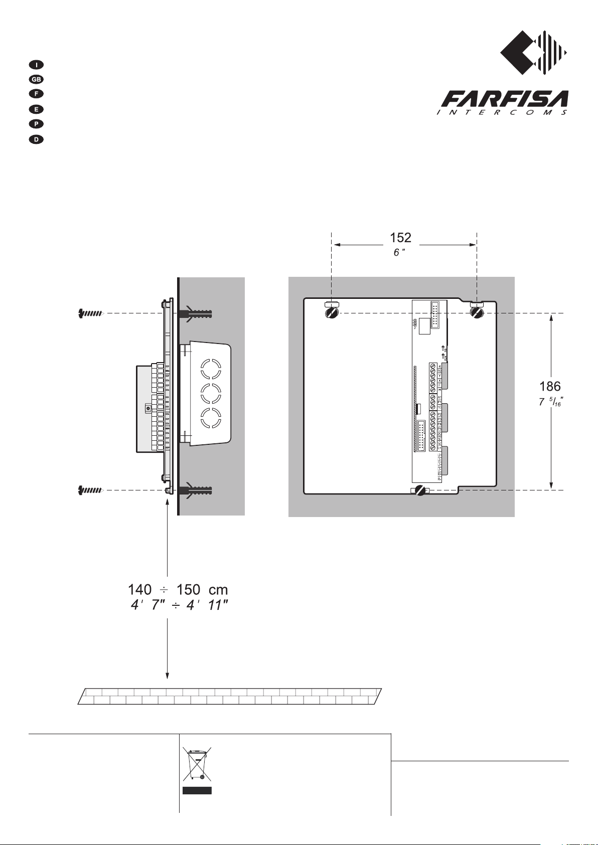
Fissaggio a parete della staffa per il montaggio dei videocitofoni EX3160
Fixing to wall of the bracket for the assemblage of the videointercoms EX3160
Fixation murale de le support pour le montage des vidéophones EX3160
Fijación a pared del soporte por el montaje des monitors EX3160
Fixação a parede do suporte para a montagem dos video-porteiros EX3160
Befestigung zu Wand vom Bügel für die Montage des Monitors EX3160
Mi 2387
La ACI Farfisa Intercoms si riserva il diritto di modificare in
qualsiasi momento i prodotti qui illustrati.
ACI Farfisa Intercoms reserves the right to modify the
products illustrated at any time.
La ACI Farfisa Intercoms se réserve le droit de modifier à
tous moments les produits illustrés.
ACI Farfisa Intercoms se reserva el derecho de modificar
todos los productos aqui ilustrados.
Änderungen vorbehalten.
Smaltire il dispositivo secondo quanto prescritto dalle norme per la
tutela dell'ambiente.
Dispose of the device in accordance with environmental regulations.
Écouler le dispositif selon tout ce qu'a été prescrit par les règles pour
la tutelle du milieu.
Eliminar el aparato según cuánto prescrito por las normas por la tutela
del entorno.
Disponha do dispositivo conforme regulamentos ambientais.
Werden Sie das Gerät in Übereinstimmung mit Umweltregulierungen
los.
ACI srl Farfisa Intercoms
Via E. Vanoni, 3 • 60027 Osimo (AN) • Italy
Tel: +39 071 7202038 (r.a.) • Fax: +39 071 7202037
e-mail: info@acifarfisa.it • www.acifarfisa.it
Morsettiera e dati elettrici
Terminal board and electrical data
Bornier et données électriques
Terminales y datos eléctricos
Terminais e dados elétricos
Klemmenbrett und elektrische Daten
Morsetti
Bornes
Terminals
Terminales
Terminais
Klemmen
4
10
Y
X
F
H
Caratteristiche
Description
Caractéristiques
Accensione di controllo (pulsante
Control switch-ON (button )
Allumage de contrôle (bouton-poussoir )
Chiamata, fonia ricezione/trasmissione, apriporta
Call, audio reception/transmission, door releasing
Appel, ligne de réception/transmission, ouvre-porte
Ingresso segnale video positivo bilanciato
Balanced positive video signal input
Entrée signal vidéo positif balancé
Ingresso segnale video negativo bilanciato
Balanced negative video signal input
Entrée signal vidéo négatif balancé
Massa generale /
Ingresso tensione positiva (18÷24Vcc)
Positive voltage input (18-24Vdc)
Entrée tension positive (18÷24Vcc)
Ground /
Masse générale
)
Descriptión
Descrição
Beschereibung
Autoencendido de control (pulsador
Acensão de controle (botão )
Taste Kontrolleinschaltung
Llamada, fonía recepción/transmisión,
Chamada, foníca recepção/transmissão, abre-porta
Anruf, Sprechweg Ein-/Ausgang, Türöffnung
Entrada señal vídeo positiva balanceada
Entrada de sinal vídeo positivo balanceado
Eingang für ausgeglichenes positive Videosignal
Entrada señal vídeo negativa balanceada
Entrada de sinal vídeo negativo balanceado
Eingang für ausgeglichenes negative Videosignal
Masa general
Entrada tensión positiva (18÷24Vcc)
Entrada tensão positiva (18÷24Vcc)
Eingang Gleichstromversorgung (18÷24Vdc)
/ Massa geral /
)
apriporta
allgemeine Masse
Ingresso chiamata elettronica di piano
A1
1C
P1 ÷ P5
2C
L1+
L1-
L+
Electronic floor call input
Entrée appel électronique d’étage
Comune dei pulsanti 1-2-3
Common for 1-2-3 push-buttons
Borne commune des poussoirs 1-2-3
Pulsanti di servizio (max 0,3A)
Service buttons (max 0.3A)
Boutons-poussoirs de service (0,3A max)
Comune dei pulsanti 4-5
Common for 4-5 push-buttons
Borne commune des poussoirs 4-5
Ingresso alimentazione positiva per Led (12Vcc)
Positive power supply input for Led (12Vdc)
Entrée tension positive pour Led (12Vcc)
Ingresso alimentazione negativa per Led
Negative power supply input for Led
Entrée tension négative pour Led
Non collegato /
Not connected
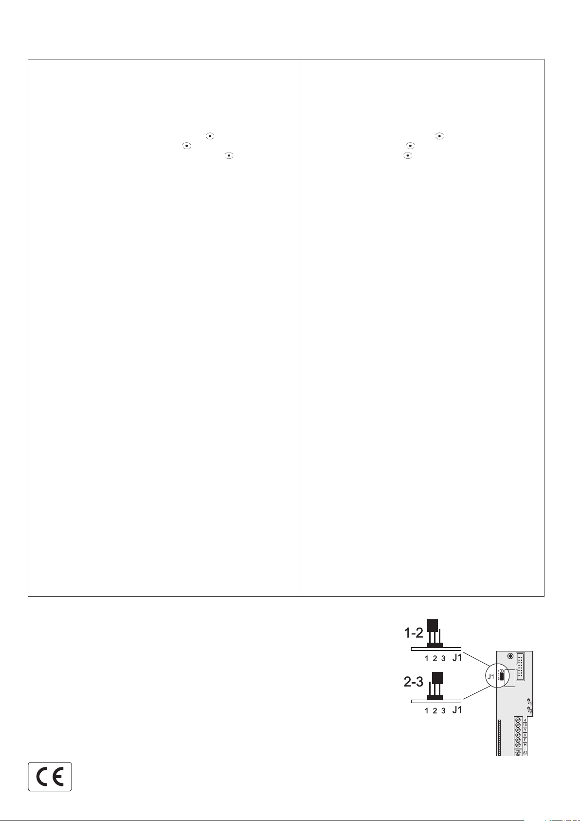
- Selezione del segreto fonico
- Selection of audio privacy
- Sélection du secret phonique
- Selección del secreto fónico
- Selecção do segredo fónico
- Selektion von Sprechgeheimnisses
Entrada llamada electrónica desde piso
Entrada chamada eletrônica de patamar
Eingang Etagen-Elektronikruf
Común pulsadores 1-2-3
Comum botões 1-2-3
Gemeinsamer Tasten 1-2-3
Pulsadores de servicio (máx 0,3A)
Botões de serviço (máx 0.3A)
Funktionstasten (max. 0,3A)
Común pulsadores 4-5
Comum botões 4-5
Gemeinsamer Tasten 4-5
Entrada tensión positiva
Entrada tensão positiva para Led (12Vcc)
Eingang positive Spannung
Entrada tensión negativa
Entrada tensão negativa para Led
Eingang negative Spannung
/ Ne réuni pas
1-2 = Videocitofono senza segreto fonico
Videointercom without private conversation
Vidéophone sans secret de conversation
Monitor sin secreto fónico
Video-porteiro sem segredo fónico
Monitor ohne Mithörsperre
2-3 = Videocitofono con segreto fonico
Videointercom with private conversation
Vidéophone avec secret de conversation
Monitor con secreto fónico
Video-porteiro com segredo fónico
Monitor mit Mithörsperre
No conectado /
para Led (12Vcc)
für Led (12Vdc)
para Led
für Led
Não conectado
/ Nicht verbunden
cod. 52704160
1+1 I
NTERCOM
*
4+1 V
IDEOINTERCOM
INSTALLATION INSTRUCTIONS
- The cable runs of intercom and video intercom installations must be kept separate
from the mains or any other electrical installation as required by the International
Safety Standards and the entire installation must be realized in compliance with the
safety rules in force in any specific Country.
- It is necessary to provide a disconnecting and safety switch before the power supply.
Use a single general switch in case of several power supplies (also in multiple entrance).
- Before connecting the power supply make sure that its rating data corresponds to this
of the mains.
- For electromagnetic reasons, all service modules must be installed near their power
supply.
Wires
1) For the correct operation of the intercom and videointercom system you must choose
the correct type of cable.
2) Wires must be dimensioned according to the distance of the different devices and their
current consumption.
3) Do not connect wires in parallel to reach the required cross-section (for example multi-
pair telephone cables). Only use a single wire with suitable cross-section. When using
multi-core cables you must select them with low parasite parameters (low capacitance
per meter, low inductance over Ohm).
4) If the installation includes additional power supplies you must place them near the
device to be powered.
Background noise
To avoid possible background noise over the speech line, it is advisable:
5) not to lay intercom or telephone cables in the same runaway as the wires used to power
alternate current loads;
6) to avoid using the same multi-core cable to transmit audio signals and alternate current
power supplies (lamps, amplified external door stations, electrical door locks). Always
use separate wires for alternate current power supplies;
7) for name-plate lamps, to use an additional 12Vac transformer (PRS210 type) with
suitable power (consumption is 75mA for each lamp) with 2 power supply wires
separate from audio wires;
8) in case of long distances between the external door station and the last intercom, to
place the power supply near by the external door station.
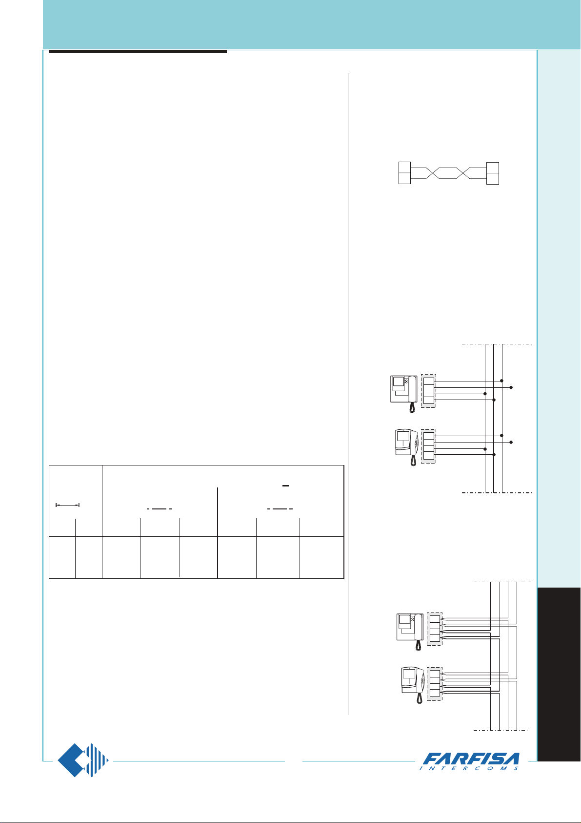
VIDEO SIGNAL DISTRIBUTION WITH
TWISTED PAIR
If the distance between the camera and the last video
intercom in the system is lower than 200 m, the connection can be made with 2x0.35mm² wires (Ø=0,6mm;
AWG22) instead of the coaxial cable. For distances
from 100m to 200m a twisted pair must be used.
For the connection of the video signal you can choose
from:
- connection with junction box
- serial connection (input and output)
- connection with floor distributors
CONNECTION WITH JUNCTION BOX
All wires are distributed in the floor junction box.
Due to the signal loss introduced by each connection,
the maximum number of video intercoms that can be
connected in serial mode is 20. Two 75Ω resistances
must be inserted between X and F and between Y and
F in the last video intercom. The maximum distance
between the video intercoms and the connector block
is 2.5 metres.
X
X
Y
Y
SERIAL CONNECTION
Connections are made on the video intercom brackets, and not in the junction box. Due to the signal loss
introduced by each connection, the maximum number
of video intercoms that can be connected in serial
mode is 20. Two 75Ω resistances must be inserted
between X and F and between Y and F in the last video
intercom.
X
Y
H
F
X
Y
H
F
PT5111
KM8111
X
Y
H
F
X
Y
H
F
PT5111
KM8111
WIRE CROSS SECTION
m.
50
100
200
mm²
S
0.5
0.75
1
mm
Ø
0.8
1
1.2
Article terminals
Distance
mm²
S
0.75
1
2
mm
Ø
1
1.2
1.4
1 . 3 (intercom)
10 . 4 . 1 . C- (videointercom)
F . H . A . S.
(wires in bold face type)
AWG
20
18
16
AWG
18
16
14
feet
165
330
660
243
(MT11 - Gb2006)

1+1 I
NTERCOM
*
4+1 V
IDEOINTERCOM
Check that the connections of the system are carried out correctly.
Put the system in use by connecting the power supply to the mains.
By pushing a call button from the external push-button panel, it activates the bell of the corresponding video intercom and it activates the
system for a time of about 100 seconds. The images appear on the
video intercom a few seconds after the call.
If in the meantime another call occurs, the video intercom shuts itself
OFF and connects the last call. The system switches OFF automatically after 100 sec.
In case more calls occur simultaneously, a protection circuit against
overloading and short circuiting is provided to disable the timer and
therefore to shut OFF the system.
In the absence of calls from the door station, from any video intercom
(if provided in the system) it is possible to control the entrance by
pressing the
button (control switch ON).
To work the electric door lock release press the
button from video
intercoms.
In the two or more entrance systems all the audio and video communications and door lock release, from one entrance to the other, are
automatically switched with the call or the control switch ON.
In these systems the control switch ON from the video intercoms can
interrupt a running communication, for this reason it is advisable to
interrupt, by means of a relay. This function when the video system is
active, giving the priority of the communication to the door stations for
some examples see pages 251 and 252.
Adjustments
All the regulations are carried out in the factory. For possible corrections the intervention of a specialized technician is advisable. The
Contrast and Brightness adjustments, being subject to the environmental lighting conditions, are accessible from the under-neath by
means of a screw driver.
WORKING INSTRUCTIONS
CONNECTION WITH FLOOR DISTRIBUTORS
The video wires of each video intercom are insulated from the riser.
Connections are made on the DV2D or DV4D floor video signal
distributor box.
Technical data
Power supply 15÷21Vdc
Operating current 60mA
Max. input video signal 2Vpp
Insertion loss 0.8dB
Bandwidth >5MHz
Connection of the video signal with distribution on several risers
In video systems with different risers you must use 1 or more video
distributors art. DV2D or DV4D.
Terminals X and Y of the last distributor must be terminated with the 75Ω
resistances supplied with the article. It is not necessary to terminate the
unused outputs.
Example of connection on 8 risers
DV2D-DV4D. FLOOR VIDEO SIGNAL DISTRIBUTORS.
They allow for the distribution of the video signal taken from the riser on
2 or 4 outputs. They can be installed on the wall on a wall box, with
expansion plugs or it can be placed in the junction box.
DV2D
DV4D
DV2D
DV4D
“ A ” “ B ” “ C ” “ D ” “ E ” “ F ” “ G ” “ H ”
X
Y
H
F
X
Y
H
F
X
Y
H
F
X
Y
H
F
X
Y
H
F
X1 X1
X1
Y1 Y1
Y1
X2 X2Y2 Y2X3 X4 X3Y3 Y4 Y3 X4 Y4
2x
75!
MD41D
Connection of the video signal on a single riser
Terminals X and Y of the last distributor must be terminated with the 75Ω
resistances supplied with the article. It is not necessary to terminate the
unused outputs.
INSTALLATION INSTRUCTIONS
X
Y
H
F
X
Y
H
F
X
Y
H
F
X
Y
H
F
X1
Y1
H
F
X1
Y1
H
F
X2
Y2
H
F
X2
Y2
H
F
DV2D
DV4D
DV2D
DV4D
X Y H F
X Y H F
X Y H F
X Y H F
2 x
75
W
PT5111
KM8111
KM8111
PT5111
25
4
"
16
/
13
122
1
2
"
16
/
11
68
"
X Y H F
3 3
X Y H F
4 4
F H Y X
F H Y X
F H Y X
2 2
F H Y X
1 1
3
"
4
/
1
83
244
(MT11 - Gb2006)

PT5111E+
WB5111E
PA
SE
MD41D
MD72
MD11ED
230V
127V
0
1181E
A
H
F
C
4
1
A
S
X
Y
H
F
10
4
X
Y
H
F
P
C
E
MA71
MA43ED
Mody
Matrix
KM8111+
WB8111
1+1 I
NTERCOM *
4+1 V
IDEOINTERCOM
Application of 3 videointercoms and 1 parallel intercom
Application of 2 videointercoms and 1 parallel
intercom
Note
In all the 4+1 video intercom systems it is possible to add further monitors and/or intercoms. To do this, insert the 2 application examples in this
page instead of the monitor which has been represented in the various installation diagrams of pages 249, 250, 251, 252 and 253.
ONE-WAY VIDEOINTERCOM SYSTEM
Application of 1 videointercom and 3 parallel intercoms
Application of 1 videointercom and 2 parallel
intercoms
230V
127V
0
1281
X
Y
H
F
10
4
A
I
A
IV
X
Y
H
F
10
4
3
1
1P
1M
H
RL37D
X
Y
H
F
10
4
VC1 VC2 VC3
CT
PT5111E+
WB5111E
KM8111+
WB8111
PT511E
KM811
230V
127V
0
PRS210
A
3
1
3
1
3
1
1P
1M
RL37D
X
Y
H
F
10
4
VC
CT3CT2CT1
PT5111E+
WB5111E
KM8111+
WB8111
PT511EPT511E
KM811KM811
3
1
3
1
VC
CT2CT1
X
Y
H
F
10
4
PT5111E+
WB5111E
KM8111+
WB8111
PT511E PT511E
KM811 KM811
Si 411R/1
Read the note on the bottom of this page Read the note on the bottom of this page
For the installation read the notes on page 243.
PA =Door release push-button (optional)
SE =Electric door lock (12VAC-1A max.)
3
1
VC1 VC2
CT
X
Y
H
F
10
4
X
Y
H
F
10
4
PT5111E+
WB5111E
PT5111E+
WB5111E
KM8111+
WB8111
KM8111+
WB8111
PT511E
KM811
249
(MT11 - Gb2006)

MULTI-WAY MIXED INTERCOM AND VIDEO INTERCOM SYSTEM CONNECTED TO 1 EXTERNAL DOOR STATION
X
Y
H
F
10
4
DV2D
DV4D
DV2D
DV4D
XXFFH
H
Y
Y
2x
75W
X F HY
X1
Y1
H
F
X1
Y1
H
F
PA
SE
H
F
X
Y
230V
127V
0
1181E
X3 Xn
MD1.ED
MD41D
P
P
P
C
C
E
P
1
A
S
E
F
H
A
C
X F HY
4
X
Y
H
F
10
4
Xn
1
3
1
6
2
3
1
6
3
7
W1
SM50
B
C
R1
Mody
MD2..
241D
MA2..
241DMA
Matrix
MA43ED
PT5111E+
WB5111E
KM8111+
WB8111
PT511E
KM811
PT511E
KM811
PT5111E+
WB5111E
KM8111+
WB8111
Conversation privacy
In case of conversation privacy function,jumper W1 of the intercom and
resistance R1 of module SM50
must be cut.
Si 41MR/2
For the installation read the notes on
pages 243 and 244.
1+1 I
NTERCOM *
4+1 V
IDEOINTERCOM
PA =Door release push-button (optional)
SE =Electric door lock (12VAC-1A max.)
Intercom without private conversation
Intercom with private conversation
250
(MT11 - Gb2006)

1+1 I
NTERCOM *
4+1 V
IDEOINTERCOM
MULTI-WAY VIDEO INTERCOM SYSTEM CONNECTED TO 2 EXTERNAL DOOR STATIONS, ONE OF WHICH ONLY AUDIO
DV2D
DV4D
DV2D
DV4D
XXFFH
H
Y
Y
2x
75!
X F HY
X1
Y1
H
F
X1
Y1
H
F
PA
PA
SE
SE
230V
127V
0
1181E
PRS210
X2X2 X3X3 XnXn
PP
PP
P
CC
C
EE
PP
1
A
S
E
F
H
A
C
X F HY
4
X
Y
H
F
10
4
Xn
1473
87
9a
8a
7a
F
H
X
Y
9b
8b
7b
4
10b
C
X
1
A
S
1
2
9
3
5
6
10
10a
X
Y
H
F
10
4
230V
127V
0
P
MD1.ED
MD41D
Mody
MD2..
241D
MD2..
MA2..
241DMA
MA2..
Matrix
MA43ED
PT5111E+
WB5111E
PT5111E+
WB5111E
KM8111+
WB8111
KM8111+
WB8111
Mody
Matrix
MD1.ED
M 1. EDA P
Si 42MR/1
Control switching ON deactivation
To activate the control switching ON from the
videointercoms only when the system is in
standby, it is necessary to install a relay (type
1471or1472) and connect it as shown on the
diagram.
PT5111E
KM8111
1181E
1473
2 2
2
5
1471
1472
2
3
2
7
4
F
H
6
For the installation read the notes on pages 243
and 244.
PA =Door release push-button (optional)
SE =Electric door lock (12VAC-1A max.)
251
(MT11 - Gb2006)

MULTI-WAY VIDEO INTERCOM SYSTEM CONNECTED TO 2 EXTERNAL DOOR STATIONS
X
Y
H
F
10
4
DV2D
DV4D
DV2D
DV4D
XXFFH
H
Y
Y
2x
75!
X F HY
X1
Y1
H
F
X1
Y1
H
F
PA
PA
SE
SE
230V
230V
127V
127V
0
0
1181E
PRS210
X2X2 X3X3 XnXn
MD41D
F
H
A
C
X F HY
4
X
Y
H
F
10
4
Xn
1473
87
9a
8a
7a
F
H
X
Y
9b
8b
7b
4
10b
X
1
2
9
3
5
6
10
10a
P
P
P
C
C
E
P
1
A
S
E
F
H
X
Y
MD1.ED
MD41D
Mody
Mody
MD2..
241D
MA2..
241DMA
Matrix
Matrix
MA43ED
PT5111E+
WB5111E
PT5111E+
WB5111E
KM8111+
WB8111
KM8111+
WB8111
P
P
C
E
P
C
1
A
S
P
MD2..
MA2..
MD1.ED
M EDA43
Si 42MR/2
Control switching ON deactivation
To activate the control switching ON from the
videointercoms only when the system is in
standby, it is necessary to install a relay (type
1471or1472) and connect it as shown on the
diagram.
PT5111E
KM8111
1181E
1473
2 2
2
5
1471
1472
2
3
2
7
4
F
H
6
For the installation read the notes on pages 243
and 244.
1+1 I
NTERCOM *
4+1 V
IDEOINTERCOM
PA =Door release push-button (optional)
SE =Electric door lock (12VAC-1A max.)
252
(MT11 - Gb2006)

1+1 I
NTERCOM *
4+1 V
IDEOINTERCOM
Si 46MR/1
- For the installation read the notes on pages 243 and 244.
- The services towards the auxiliary entrances are independent among themselves
and therefore they can function at the same time.
DV2D
DV4D
“ A ” “ B ”
“ C - D - .. ”
230V
127V
0
4 4
10 109 9
8 8
xn(C)
x1(C)
xn(B)
xn(A)
xn(A) xn(B)
1473 1473
“ C - D - .. ”
6 (C)
X
Y
F
H
10
4
X
Y
F
H
10
4
X
Y
F
H
10
4
X
Y
F
H
10
4
X
Y
X
Y
DV2D
DV4D
DV2D
DV4D
DV2D
DV4D
DV2D
DV4D
X X
X X
Y Y
Y Y
F F
F F
H H
H H
2x
75W
2x
75W
X XY YF FH H
X XY YF FH H
X1
Y1
F
H
X1
Y1
F
H
X1
Y1
F
H
X1
Y1
F
H
Y1
X1
X2
Y2
PA
SE
H
F
X
Y
1181E
PA PA
SE SE
F
H
X
Y
F
H
X
Y
xn(A) xn(B)
MA2..
241DMA
MA2..
241DMA
P P
P P
C C
C C
E E
P P
1 1
A
S
A
S
E E
230V
230V
127V
127V
0
0
1181E 1181E
F F
H H
4 4
C C
7b
2
1
7b
2
1
3
7
3
7
A A
8b
9b
10b
8b
9b
10b
5 5
6 67a 7a8a 8a9a 9a10a 10a
AF 3+ 4
H
C
X
F
H
x3(A) x3(B)
x2(A) x2(B)
P P
1
A
S
MD41D
Mody Mody
Matrix Matrix
MD2..
MA2..
MD1.ED
M EDA43
MD2..
241D
MD2..
241D
MD41D MD41D
MD1.ED MD1.ED
M EDA43 M EDA43
PT5111E+
WB5111E
PT5111E+
WB5111E
PT5111E+
WB5111E
PT5111E+
WB5111E
KM8111+
WB8111
KM8111+
WB8111
KM8111+
WB8111
KM8111+
WB8111
PA =Door release push-button (optional)
SE = Electric door lock (12VAC-1A max.)
MULTI-WAY VIDEO INTERCOM SYSTEM WITH SECONDARY VIDEO STATIONS AND 1 MAIN COMMON VIDEO STATION (multiple
entrance)
common of buttons 1 and
2
to separate the common of
buttons cut here
common of buttons 3 and
4
The main entrance push-button panel must
have separate common terminals. One common
terminal for each secondary door station. Buttons of
the Mody series can be divided into 2-button groups.
Common terminals of Matrix push buttons cannot
be separated.
Mody series button module
253
(MT11 - Gb2006)

Si 46MR/2
- For the installation read the notes on pages 243 and 244.
- The services towards the auxiliary entrances are independent among themselves
and therefore they can function at the same time.
DV2D
DV4D
“ A ” “ B ”
“ C - D - .. ”
230V
127V
0
4 4
10 109 9
8 8
xn(C)
x1(C)
xn(B)
xn(A)
xn(A) xn(B)
1473 1473
“ C - D - .. ”
6 (C)
X
Y
F
H
10
4
X
Y
F
H
10
4
X
Y
F
H
10
4
X
Y
F
H
10
4
X
Y
X
Y
DV2D
DV4D
DV2D
DV4D
DV2D
DV4D
DV2D
DV4D
X X
X X
Y Y
Y Y
F F
F F
H H
H H
2x
75W
2x
75W
X XY YF FH H
X XY YF FH H
X1
Y1
F
H
X1
Y1
F
H
X1
Y1
F
H
X1
Y1
F
H
Y1
X1
X2
Y2
PA
SE
H
F
X
Y
1181E
PA PA
SE SE
xn(A) xn(B)
MA2..
241DMA
MA2..
241DMA
P P
P P
C C
C C
E E
P P
1 1
A
S
A
S
E E
230V
230V
127V
127V
0
0
1181E 1181E
F F
H H
4 4
C C
7b
2
1
7b
2
1
3
7
3
7
A A
8b
9b
10b
8b
9b
10b
5 5
6 67a 7a8a 8a9a 9a10a 10a
AF 3+ 4
H
C
X
F
H
x3(A) x3(B)
x2(A) x2(B)
P P
1
A
S
MD41D
Mody Mody
Matrix Matrix
MD2..
MA2..
MD1.ED
M EDA43
MD2..
241D
MD2..
241D
MD1.ED MD1.ED
M EDA1.P M EDA1.P
PT5111E+
WB5111E
PT5111E+
WB5111E
PT5111E+
WB5111E
PT5111E+
WB5111E
KM8111+
WB8111
KM8111+
WB8111
KM8111+
WB8111
KM8111+
WB8111
PA =Door release push-button (optional)
SE =Electric door lock (12VAC-1A max.)
MULTI-WAY VIDEO INTERCOM SYSTEM WITH SECONDARY DOOR STATIONS ONLY AUDIO AND 1 MAIN COMMON VIDEO
STATION (multiple entrance)
1+1 I
NTERCOM *
4+1 V
IDEOINTERCOM
common of buttons 1 and
2
to separate the common of
buttons cut here
common of buttons 3 and
4
The main entrance push-button panel must
have separate common terminals. One common
terminal for each secondary door station. Buttons of
the Mody series can be divided into 2-button groups.
Common terminals of Matrix push buttons cannot
be separated.
Mody series button module
254
(MT11 - Gb2006)
 Loading...