

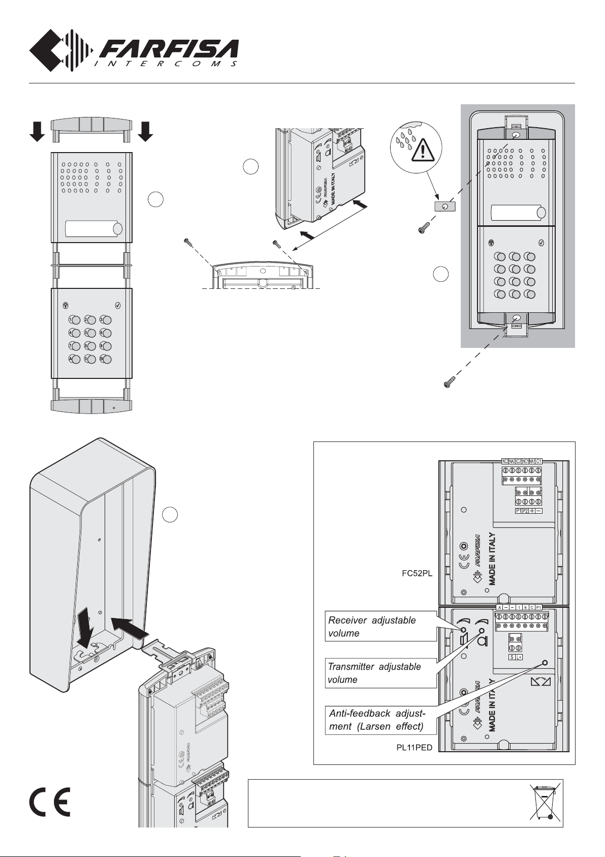
Installation of the push-button panel
1
Mi 2451
(English)
3
Fix lower part of the frame to the
rain shelter and make the electrical connections.
ONE-W A Y AUDIO KIT
1PEXFD
123
4
456
789
0BA
Mounting modules.
Fixing of frame to rain shelter. Align the frame before
tightening the screws.
ADJUSTMENTS
2
Fixing of the module frames on the
upper side by the 2 small screws
included in the rain shelter.
ACI srl Farfisa Intercoms
Via E. Vanoni, 3 • 60027 Osimo (AN) • Italy
Tel: +39 071 7202038 (r.a.) • Fax: +39 071 7202037
e-mail: info@acifarfisa.it • www.acifarfisa.it
ACI Farfisa Intercoms reserves the right to modify the products illustrated at any time.
Dispose of the device in accordance
with environmental regulations.
- 1 -
cod. 52704910
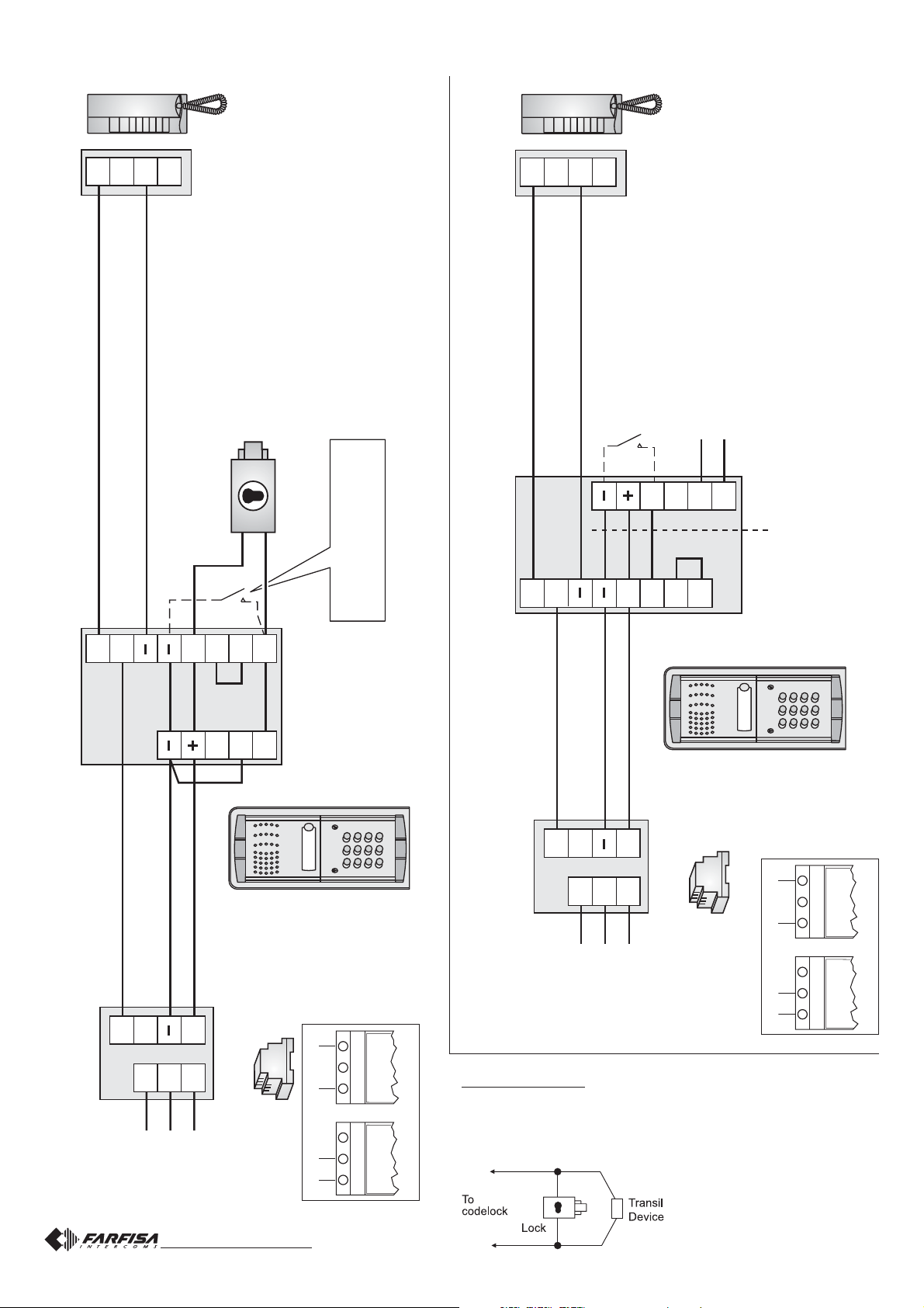
INSTALLATION DIAGRAMS
1
6
3
7
INTERCOM
EX321
Do not forget to connect
terminals 1 and E
*
1
6
INTERCOM
3
7
EX321
EXIT PUSHBUTTON
(optional)
TO AUTOMATIC GATE
PUSHBUTTON PANEL
P1
P1
NC1
C1
NA1
FC52PLPL11PED
ELECTRIC DOOR LOCK (12Vac - 1A)
*
Do not forget to connect
terminals 1 and E
*
1
C
EXIT PUSHBUTTON
(optional)
1
C
A
E
S
-The cables, which are heavily outlined, have a minimum section of 0.75mm² (AWG18).
P1
PUSHBUTTON PANEL
A
S
*
C1
NC1
NA1
FC52PL PL11PED
1 2 3
PL92
7 8 9
4 5 6
PL11PED
FC52PL
0 BA
C-
A
POWER SUPPLY
E
PRS210ED
1 2 3
PL92
7 8 9
4 5 6
PL11PED
FC52PL
0 BA
127V0 230V
-The cables, which are heavily outlined, have a minimum section of 0.75mm² (AWG18).
0
PRS210ED
127V
220-230V
127V
A
0
PRS210ED
110-127Vac 220-230Vac
127V0 230V
127V0 230V
PRS210ED
VERY IMPORTANT
T o comply with the European Standards on Electromagnetic Compatibility and to increase the reliability of the product, it is necessary to
connect a suppression device when switching inductive loads i.e.
electric releases and electric locks.
The enclosed suppression devices
(transil) must be connected as close
C-
POWER SUPPLY
220-230V
127V0 230V
110-127Vac 220-230Vac
as possible to the loads (ideally
- 2 -
across the terminals. See figure).
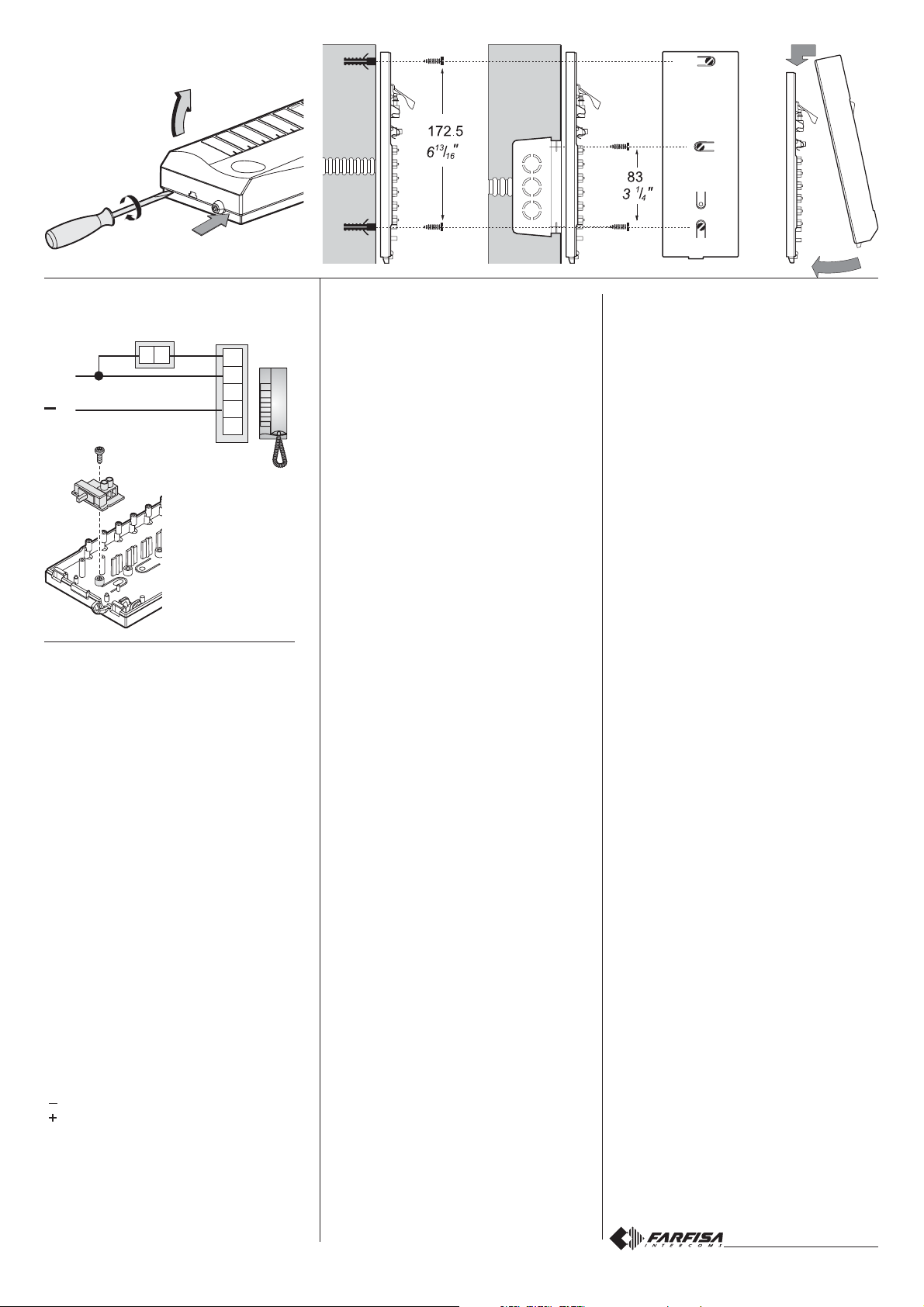
Installation of the intercom
Ringer volume adjusting (optional)
P1
ST703 (*)
C
9
ST703 (*)
INTERCOM
A1
6
1
3
7
EX321
(*) not included
in the kit
ACCESS CONTROL KEYP AD
The keypad allows for the activation of 2
relays with programmable codes.
Technical data
Power supply 12Vac/dc ±10%
Stand-by current 0.06A
Maximum current consumption 0.15A
Contact ratings 12Vac - 2A
Number of codes for relay 1 12 (+ direct
activation)
Number of codes for relay 2 12 (+ direct
activation)
Activation time for each relay from 1 to 99 sec.
(or bistable)
Operating temperature 0° ÷ +40°C
Maximum allowable humidity 85% RH
Terminals
NC2 normally closed contact of relay 2
NA2 normally open contact of relay 2
C2 common contact of relay 2
NC1 normally closed contact of relay 1
NA1 normally open contact of relay 1
C1 common contact of relay 1
ground or alternate voltage input
positive or alternate voltage input
P2 activation of the relay 2; if momentarily
connected to ground it allows the activation for the programmed time
P1 activation of the relay 1; if momentarily
connected to ground it allows the activation for the programmed time
PROGRAMMING
Default programming
The article is supplied from the factory with
the following codes:
Programming code: 11
Activation code 1 of relay 1: 12345678
Other activation codes of relay 1
(from 2 to 12): none
Activation time code of relay 1: 01 (1 sec.)
Operating mode of relay 1: 00 (monostable)
Activation code 1 of relay 2: 90
Other activation codes of relay 2
(from 2 to 12): none
Activation time code of relay 2: 01 (1 sec.)
Operating mode of relay 2: 00 (monostable)
All codes are user-modifiable.
Operating modes and programming codes
Monostable 00
Bistable 01
Monostable and direct activat. by key A02
Bistable and direct activation by key A03
Changing the programming code
T o change the programming code:
- enter the actual programming code
- press key A (red LED flashes)
- enter 00
- press key A (red LED on)
- enter the new programming code with 1 to 8
digits (from 0 to 99999999)
- press key A (red LED flashes)
- enter 55
- press key A (red LED off).
Changing the activation codes of relay 1
T o change the activation codes of relay 1:
- enter the programming code
- press key A (red LED flashes)
- enter 01 (identification code of relay 1)
- press key A (red LED on)
- enter a number with 1 to 8 digits to programme code 1 (from 0 to 99999999)
- press key A
- enter a number with 1 to 8 digits to programme code 2 (from 0 to 99999999)
- press key A
- enter a number with 1 to 8 digits to programme code 3 (from 0 to 99999999)
- press key A
- repeat the operation to programme all codes
as necessary (max.12). When program-
ming is completed press key A repeatedly
until the red LED starts flashing
- enter 55
- press A (red LED off).
Changing the activation codes of relay 2
To change the activation codes of relay 2
follow the procedure described above, changing the relay identification code (02 instead of
01).
Changing one relay activation code
T o change one relay activation code, without
modifying the others:
- enter the programming code
- press key A (red LED flashes)
- enter 01 or 02 (for relay 1 or 2, respectively)
- press key A (red LED on)
- press key A repeatedly to reach the code to
be changed
- enter a number with 1 to 8 digits (from 0 to
99999999)
- press key A repeatedly until the red LED
starts flashing
- enter 55
- press key A (red LED off).
Example
T o change activation code 7 of relay 2:
- enter the programming code
- press key A (red LED flashes)
- enter 02
- press key A (red LED on)
- press key A six times
- enter a number with 1 to 8 digits
- press key A six times (red LED flashes)
- enter 55
- press key A (red LED off).
Deleting one relay activation code
T o delete one relay activation code, without
modifying the others:
- enter the programming code
- press key A (red LED flashes)
- enter 90
- press key A (red LED on)
- enter a 3-digit number “nxx”; n indicates the
relay associated with the code to be deleted
(1 or 2); xx indicates the code to be deleted
(from 01 to 12)
- press key A (red LED flashes)
- enter 55
- press key A (red LED off).
- 3 -
 Loading...