

Page 1

CNC
8055 ·T·
Programming manual
Ref. 1310
Soft: V01.4x
Page 2

It is possible that CNC can execute more functions than those described in its
associated documentation; however, Fagor Automation does not guarantee the
validity of those applications. Therefore, except under the express permission
from Fagor Automation, any CNC application that is not described in the
documentation must be considered as "impossible". In any case, Fagor
Automation shall not be held responsible for any personal injuries or physical
All rights reserved. No part of this documentation may be transmitted,
transcribed, stored in a backup device or translated into another language
without Fagor Automation’s consent. Unauthorized copying or distributing of this
software is prohibited.
The information described in this manual may be subject to changes due to
technical modifications. Fagor Automation reserves the right to change the
contents of this manual without prior notice.
All the trade marks appearing in the manual belong to the corresponding owners.
The use of these marks by third parties for their own purpose could violate the
rights of the owners.
This product uses the following source code, subject to the terms of the GPL license. The applications busybox V0.60.2;
dosfstools V2.9; linux-ftpd V0.17; ppp V2.4.0; utelnet V0.1.1. The librarygrx V2.4.4. The linux kernel V2.4.4. The linux boot
ppcboot V1.1.3. If you would like to have a CD copy of this source code sent to you, send 10 Euros to Fagor Automation
for shipping and handling.
damage caused or suffered by the CNC if it is used in any way other than as
explained in the related documentation.
The content of this manual and its validity for the product described here has been
verified. Even so, involuntary errors are possible, hence no absolute match is
guaranteed. However, the contents of this document are regularly checked and
updated implementing the necessary corrections in a later edition. We appreciate
your suggestions for improvement.
The examples described in this manual are for learning purposes. Before using
them in industrial applications, they must be properly adapted making sure that
the safety regulations are fully met.
Page 3

Programming manual
INDEX
About the product ......................................................................................................................... 7
Declaration of conformity.............................................................................................................. 9
Version history............................................................................................................................ 11
Safety conditions ........................................................................................................................ 13
Warranty terms ........................................................................................................................... 17
Material returning terms.............................................................................................................. 19
Additional remarks ...................................................................................................................... 21
Fagor documentation.................................................................................................................. 23
CHAPTER 1 GENERAL CONCEPTS
1.1 Part programs ................................................................................................................26
1.1.1 Considerations regarding the Ethernet connection .................................................... 28
1.2 DNC connection............................................................................................................. 29
1.3 Communication protocol via DNC or peripheral device ................................................. 30
CHAPTER 2 CREATING A PROGRAM
2.1 Program structure at the CNC ....................................................................................... 32
2.1.1 Block header .............................................................................................................. 32
2.1.2 Program block............................................................................................................ 33
2.1.3 End of block ...............................................................................................................34
CHAPTER 3 AXES AND COORDINATE SYSTEMS
3.1 Axis nomenclature ......................................................................................................... 36
3.1.1 Axis selection .............................................................................................................37
3.2 Plane selection (G16, G17, G18, G19) .......................................................................... 38
3.3 Part dimensioning. Millimeters (G71) or inches (G70) ................................................... 39
3.4 Absolute/incremental programming (G90, G91) ............................................................ 40
3.5 Programming in radius or in diameters (G152, G151) ................................................... 41
3.6 Coordinate programming ............................................................................................... 42
3.6.1 Cartesian coordinates ................................................................................................ 43
3.6.2 Polar coordinates ....................................................................................................... 44
3.6.3 Angle and Cartesian coordinate................................................................................. 46
3.7 Rotary axes.................................................................................................................... 47
3.8 Work zones.................................................................................................................... 48
3.8.1 Definition of the work zones ....................................................................................... 48
3.8.2 Using the work zones................................................................................................. 49
CHAPTER 4 REFERENCE SYSTEMS
4.1 Reference points............................................................................................................ 51
4.2 Machine reference (Home) search (G74) ...................................................................... 52
4.3 Programming with respect to machine zero (G53) ........................................................ 53
4.4 Coordinate preset and zero offsets................................................................................ 54
4.4.1 Coordinate preset and S value limitation (G92) ......................................................... 55
4.4.2 Zero offsets (G54..G59 and G159) ............................................................................ 56
4.5 Polar origin preset (G93)................................................................................................ 58
CHAPTER 5 ISO CODE PROGRAMMING
5.1 Preparatory functions..................................................................................................... 60
5.2 Feedrate F ..................................................................................................................... 62
5.2.1 Feedrate in mm/min or inches/min (G94)................................................................... 63
5.2.2 Feedrate in mm/rev.or inches/rev (G95) .................................................................... 64
5.3 Spindle speed (S) .......................................................................................................... 65
5.3.1 Constant surface speed (G96) ................................................................................... 66
5.3.2 Spindle speed in rpm (G97) ....................................................................................... 67
5.4 Spindle selection (G28, G29)......................................................................................... 68
5.5 Synchronized spindles (G30, G77S, G78S) .................................................................. 69
5.6 Tool number (T) and tool offset (D)................................................................................ 70
CNC 8055
CNC 8055i
SOFT: V01.4X
·3·
Page 4

5.7 Auxiliary function (M) ..................................................................................................... 72
5.7.1 M00. Program stop .................................................................................................... 73
5.7.2 M01. Conditional program stop.................................................................................. 73
5.7.3 M02. End of program ................................................................................................. 73
5.7.4 M30. End of program with return to the first block ..................................................... 73
5.7.5 M03, M4, M5. Spindle start and stop ......................................................................... 73
5.7.6 M06. Tool change code ............................................................................................. 75
5.7.7 M19. Spindle orientation ............................................................................................ 75
5.7.8 M41, M42, M43, M44. Spindle gear change .............................................................. 76
5.7.9 M45. Auxiliary spindle / Live tool................................................................................ 77
CHAPTER 6 PATH CONTROL
6.1 Rapid traverse (G00) ..................................................................................................... 80
6.2 Linear interpolation (G01) .............................................................................................. 81
6.3 Circular interpolation (G02, G03)................................................................................... 82
6.4 Circular interpolation with absolute arc center coordinates (G06) ................................. 86
6.5 Arc tangent to previous path (G08)................................................................................ 87
6.6 Arc defined by three points (G09).................................................................................. 88
6.7 Helical interpolation ....................................................................................................... 89
6.8 Tangential entry at the beginning of a machining operation (G37) ................................ 90
6.9 Tangential exit at the end of a machining operator (G38) ............................................. 91
6.10 Automatic radius blend (G36) ........................................................................................ 92
6.11 Chamfer (G39)...............................................................................................................93
6.12 Threading (G33) ............................................................................................................ 94
6.13 Withdrawal of axes when interrupting a threading operation (G233)............................. 97
6.14 Variable pitch threads (G34).......................................................................................... 99
6.15 Activates the C axis (G15). .......................................................................................... 100
6.15.1 Machining on the side of the part............................................................................. 101
6.15.2 Machining on the face of the part............................................................................. 102
6.16 Move to hardstop (G52)............................................................................................... 103
6.17 Feedrate "F" as an inverted function of time (G32)...................................................... 104
6.18 Tangential control (G45) .............................................................................................. 105
6.18.1 Considerations about the G45 function.................................................................... 107
6.19 G145. Temporary cancellation of tangential control .................................................... 108
Programming manual
CNC 8055
CNC 8055i
SOFT: V01.4X
CHAPTER 7 ADDITIONAL PREPARATORY FUNCTIONS
7.1 Interruption of block preparation (G04)........................................................................ 109
7.1.1 G04 K0: Block preparation interruption and coordinate update ............................... 111
7.2 Dwell (G04 K) .............................................................................................................. 112
7.3 Working with square (G07) and round (G05,G50) corners.......................................... 113
7.3.1 G07 (square corner)................................................................................................. 113
7.3.2 G05 (round corner) .................................................................................................. 114
7.3.3 Controlled round corner (G50) ................................................................................. 115
7.4 Look-ahead (G51)........................................................................................................ 116
7.4.1 Advanced look-ahead algorithm (integrating Fagor filters) ...................................... 118
7.4.2 Look-ahead operation with Fagor filters active ........................................................ 119
7.5 Mirror image (G10, G11. G12, G13, G14) ................................................................... 120
7.6 Scaling factor (G72)..................................................................................................... 121
7.6.1 Scaling factor applied to all axes. ............................................................................ 122
7.6.2 Scaling factor applied to one or more axes.............................................................. 123
7.7 Electronic axis coupling/uncoupling............................................................................. 125
7.7.1 Electronic axis coupling, slaving, (G77) ................................................................... 126
7.7.2 Cancellation of the electronic axis coupling, slaving, (G78)..................................... 127
7.8 Axes toggle G28-G29 .................................................................................................. 128
CHAPTER 8 TOOL COMPENSATION
8.1 Tool length compensation............................................................................................ 129
8.2 Tool radius compensation............................................................................................ 130
8.2.1 The location code of the tool (tool type)................................................................... 131
8.2.2 Working without tool radius compensation .............................................................. 134
8.2.3 Working with tool radius compensation ................................................................... 135
8.2.4 Beginning of tool radius compensation (G41, G42) ................................................. 136
8.2.5 Sections of tool radius compensation ...................................................................... 139
8.2.6 Cancellation of tool radius compensation (G40) ...................................................... 140
8.2.7 Temporary cancellation of tool compensation with G00 .......................................... 144
8.2.8 Change of type of tool radius compensation while machining ................................. 146
8.2.9 Tool compensation in any plane .............................................................................. 147
8.3 Collision detection (G41 N, G42 N) ............................................................................. 148
·4·
Page 5

Programming manual
CHAPTER 9 CANNED CYCLES
9.1 G66. Pattern repeat cycle canned cycle ...................................................................... 150
9.1.1 Basic operation ........................................................................................................ 153
9.1.2 Profile programming syntax ..................................................................................... 155
9.2 G68. X axis roughing canned cycle ............................................................................. 156
9.2.1 Basic operation ........................................................................................................ 159
9.2.2 Profile programming syntax ..................................................................................... 162
9.3 G69. Z axis roughing canned cycle.............................................................................. 163
9.3.1 Basic operation ........................................................................................................ 166
9.3.2 Profile programming syntax ..................................................................................... 169
9.4 G81. Turning canned cycle for straight sections.......................................................... 170
9.4.1 Basic operation ........................................................................................................ 172
9.5 G82. Facing canned cycle for straight sections ........................................................... 174
9.5.1 Basic operation ........................................................................................................ 176
9.6 G83. Axial drilling and tapping canned cycle ............................................................... 178
9.6.1 Basic operation ........................................................................................................ 180
9.7 G84. Turning canned cycle for curved sections........................................................... 181
9.7.1 Basic operation ........................................................................................................ 183
9.8 G85. Facing canned cycle for curved sections ............................................................ 185
9.8.1 Basic operation ........................................................................................................ 187
9.9 G86. Longitudinal threading canned cycle................................................................... 189
9.9.1 Basic operation ........................................................................................................ 194
9.10 G87. Face threading canned cycle .............................................................................. 195
9.10.1 Basic operation ........................................................................................................ 201
9.11 G88. X axis grooving canned cycle.............................................................................. 202
9.11.1 Basic operation ........................................................................................................ 203
9.12 G89. Z axis grooving canned cycle.............................................................................. 204
9.12.1 Basic operation ........................................................................................................ 205
9.13 G60. Axial drilling / tapping (on the face) ..................................................................... 206
9.13.1 Basic operation ........................................................................................................ 208
9.14 G61. Radial drilling/ tapping (on the side of the part)................................................... 210
9.14.1 Basic operation ........................................................................................................ 212
9.15 G62. Slot milling canned cycle on the side of the part ................................................. 214
9.15.1 Basic operation ........................................................................................................ 216
9.16 G63. Slot milling canned cycle on the face of the part................................................. 217
9.17 Basic operation ............................................................................................................ 219
CHAPTER 10 PROBING
10.1 Probing (G75, G76)...................................................................................................... 222
10.2 Probing canned cycles................................................................................................. 223
10.3 PROBE 1. Tool calibration canned cycle ..................................................................... 224
10.3.1 Basic operation ........................................................................................................ 227
10.4 PROBE 2. Probe calibration canned cycle. ................................................................. 230
10.4.1 Basic operation ........................................................................................................ 231
10.5 PROBE 3. Canned cycle for part measuring and tool correction on the X axis ........... 233
10.5.1 Basic operation ........................................................................................................ 234
10.6 PROBE 4. Canned cycle for part measuring and tool correction on the Z axis ........... 235
10.6.1 Basic operation ........................................................................................................ 236
CHAPTER 11 HIGH-LEVEL LANGUAGE PROGRAMMING
11.1 Lexical description ....................................................................................................... 237
11.2 Variables ...................................................................................................................... 239
11.2.1 General purpose parameters or variables................................................................ 240
11.2.2 Variables associated with tools. ............................................................................... 242
11.2.3 Variables associated with zero offsets. .................................................................... 245
11.2.4 Variables associated with machine parameters....................................................... 246
11.2.5 Variables associated with work zones ..................................................................... 247
11.2.6 Variables associated with feedrates......................................................................... 249
11.2.7 Variables associated with coordinates ..................................................................... 251
11.2.8 Variables associated with electronic handwheels .................................................... 253
11.2.9 Variables associated with feedback ......................................................................... 255
11.2.10 Variables associated with the main spindle ............................................................. 256
11.2.11 Variables associated with the second spindle.......................................................... 259
11.2.12 Variables associated with the live tool ..................................................................... 262
11.2.13 PLC related variables............................................................................................... 263
11.2.14 Variables associated with local parameters ............................................................. 265
11.2.15 Sercos variables....................................................................................................... 266
11.2.16 Software & hardware configuration variables........................................................... 267
11.2.17 Variables associated with telediagnosis................................................................... 270
11.2.18 Operating-mode related variables............................................................................ 273
11.2.19 Other variables......................................................................................................... 276
11.3 Constants..................................................................................................................... 281
CNC 8055
CNC 8055i
SOFT: V01.4X
·5·
Page 6

11.4 Operators..................................................................................................................... 282
11.5 Expressions ................................................................................................................. 284
11.5.1 Arithmetic expressions............................................................................................. 284
11.5.2 Relational expressions............................................................................................. 285
CHAPTER 12 PROGRAM CONTROL INSTRUCTIONS
12.1 Assignment instructions............................................................................................... 288
12.2 Display instructions...................................................................................................... 289
12.3 Enable-disable instructions.......................................................................................... 290
12.4 Flow control instructions .............................................................................................. 291
12.5 Subroutine instructions ................................................................................................ 293
12.6 Probe related instructions ............................................................................................ 297
12.7 Interruption-subroutine instructions ............................................................................. 298
12.8 Program instructions.................................................................................................... 299
12.9 Screen customizing instructions .................................................................................. 302
CHAPTER 13 ANGULAR TRANSFORMATION OF AN INCLINE AXIS
13.1 Turning angular transformation on and off................................................................... 309
13.2 Freezing the angular transformation............................................................................ 310
APPENDIX
A ISO code programming................................................................................................ 313
B Program control instructions ........................................................................................ 315
C Summary of internal CNC variables. ........................................................................... 319
D Key code...................................................................................................................... 327
E Programming assistance screens of the system. ........................................................ 337
F Maintenance ................................................................................................................ 341
Programming manual
CNC 8055
CNC 8055i
SOFT: V01.4X
·6·
Page 7
ABOUT THE PRODUCT
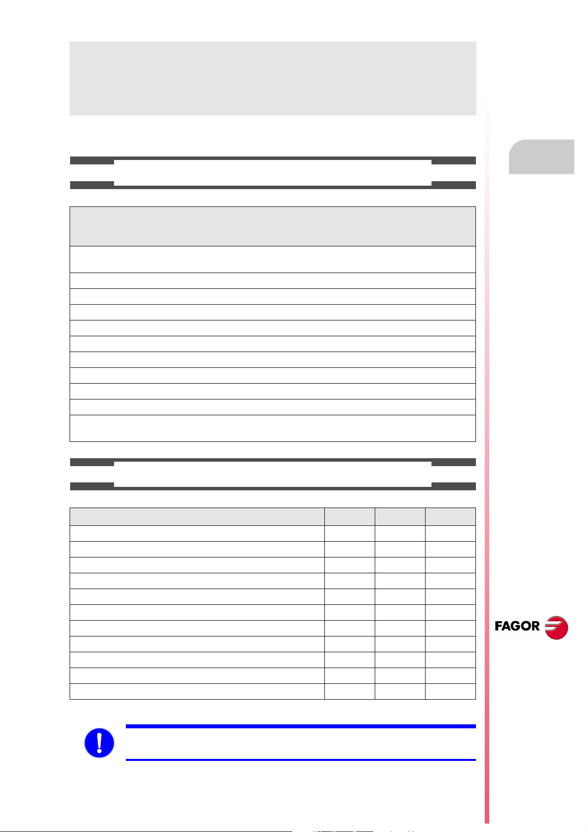
BASIC CHARACTERISTICS OF THE DIFFERENT MODELS.
8055 FL
8055i FL
8055i FL EN
Built-in 8055i FL
8055i FL EN
Enclosure 8055 FL 8055 Power
USB Standard Standard
Block processing time 3.5 ms 0.9 ms
RAM memory 1Mb 1 Mb
Software for 7 axes ----- Option
TCP transformation ----- Option
C axis (Lathe) ----- Option
Y axis (Lathe) ----- Option
Look-ahead 100 blocks 200 blocks
Flash Memory 512Mb / 2Gb Option
512Mb on the EN model
8055 Power
8055i Power
8055i Power
Option
HARDWARE OPTIONS OF THE 8055I CNC
Analog Digital Engraving
Ethernet Option Option Option
RS-232 serial line Standard Standard Standard
16 digital inputs and 8 outputs (I1 to I16 and O1 to O8) Standard Standard Standard
Another 40 digital inputs and 24 outputs (I65 to I104 and O33 to O56) Option Option Option
Probe inputs Standard Standard Standard
Spindle (feedback input and analog output) Standard Standard Standard
Electronic handwheels Standard Standard Standard
4 axes (feedback and velocity command) Option Option - - -
Remote CAN modules, for digital I/O expansion (RIO). Option Option - - -
Sercos servo drive system for Fagor servo drive connection. - - - Option - - -
CAN servo drive system for Fagor servo drive connection. - - - Option - - -
Before start-up, verify that the machine that integrates this CNC meets the 89/392/CEE Directive.
CNC 8055
CNC 8055i
·7·
Page 8
About the product
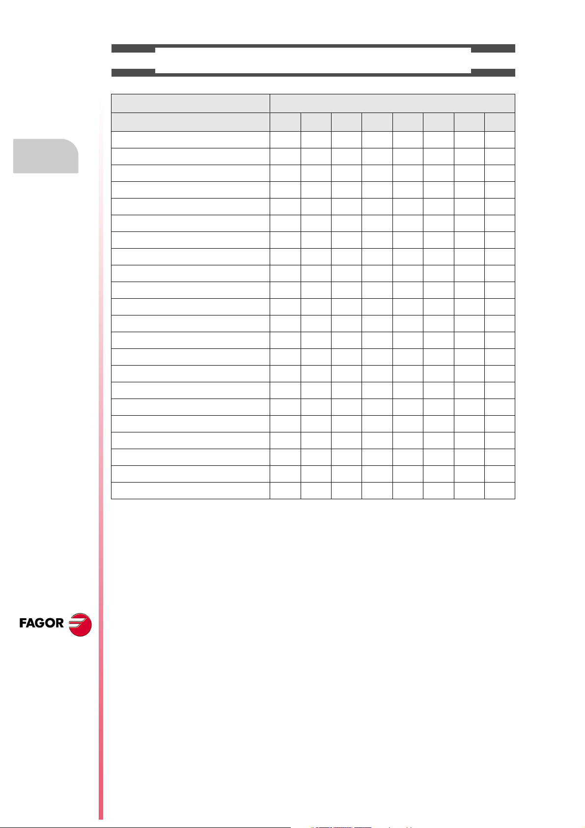
SOFTWARE OPTIONS OF THE 8055 AND 8055I CNCS.
Model
GP M MC MCO EN T TC TCO
Number of axes with standard software 4 4 4 4 3 2 2 2
Number of axes with optional software 7 7 7 7 ----- 4 or 7 4 or 7 4 or 7
Electronic threading ----- Stand. Stand. Stand. Stand. Stand. Stand. Stand.
Tool magazine management: ----- Stand. Stand. Stand. ----- Stand. Stand. Stand.
Machining canned cycles ----- Stand. Stand. ----- Stand. Stand. Stand. -----
Multiple machining ----- Stand. Stand. ----- Stand. ----- ----- -----
Solid graphics ----- Stand. Stand. Stand. ----- Stand. Stand. Stand.
Rigid tapping ----- Stand. Stand. Stand. Stand. Stand. Stand. Stand.
Tool live monitoring ----- Opt. Opt. Opt. Stand. Opt. Opt. Opt.
Probing canned cycles ----- Opt. Opt. Opt. Stand. Opt. Opt. Opt.
DNC Stand. Stand. Stand. Stand. Stand. Stand. Stand. Stand.
COCOM version Opt. Opt. Opt. Opt. ----- Opt. Opt. Opt.
Profile editor Stand. Stand. Stand. Stand. ----- Stand. Stand. Stand.
Tool radius compensation Stand. Stand. Stand. Stand. Stand. Stand. Stand. Stand.
CNC 8055
CNC 8055i
Tangential control Opt. Opt. Opt. Opt. ----- Opt. Opt. Opt.
Retracing ----- Opt. Opt. Opt. Stand. Opt. Opt. Opt.
Setup assistance Stand. Stand. Stand. Stand. Stand. Stand. Stand. Stand.
Irregular pockets with islands ----- Stand. Stand. Stand. ----- ----- ----- -----
TCP transformation ----- Opt. Opt. Opt. ----- ----- ----- -----
C axis (on Lathe) ----- ----- ----- ----- ----- Opt. Opt. Opt.
Y axis (on Lathe) ----- ----- ----- ----- ----- Opt. Opt. Opt.
Telediagnosis Opt. Opt. Opt. Opt. Stand. Opt. Opt. Opt.
·8·
Page 9
DECLARATION OF CONFORMITY
The manufacturer:
Fagor Automation S. Coop.
Barrio de San Andrés Nº 19, C.P. 20500, Mondragón -Guipúzcoa- (SPAIN).
Declares:
Under their responsibility that the product:
8055 / 8055i CNC
Consisting of the following modules and accessories:
MONITOR-8055, MONITOR-55-11-USB
OP-8055
KS 50/55, KB-40/55-ALFA, DVD AMPLI 8055
PSB-8055
CPU-KEY CF 8055 FL LARGE, CPU-KEY CF 8055 Power LARGE
AXES 8055 VPP
I/O 8055, COVER 8055, SERCOS 8055
Remote modules RIO
CNC 8055i FL, CNC 8055i Power
ANALOG 8055i-B, 40I/24O-8055i-B, ANALOG+40I/24O-B, COVER ANA+I/O-8055i-B
ETHERNET-CAN-SERCOS, ETHERNET-CAN-CAN AXES, ETHERNET-CAN AXES
Note.
Some additional characters may follow the references mentioned above. They all comply with the directives
listed. However, check that that's the case by checking the label of the unit itself.
Referred to by this declaration with following directives:
Low voltage regulations.
EN 60204-1: 2006 Electrical equipment on machines — Part 1. General requirements.
Regulation on electromagnetic compatibility.
EN 61131-2: 2007 PLC — Part 2. Requirements and equipment tests.
As instructed by the European Community Directives 2006/95/EEC on Low Voltage and
2004/108/EC on Electromagnetic Compatibility and its updates.
In Mondragón, July 27th, 2010.
CNC 8055
CNC 8055i
·9·
Page 10

Page 11
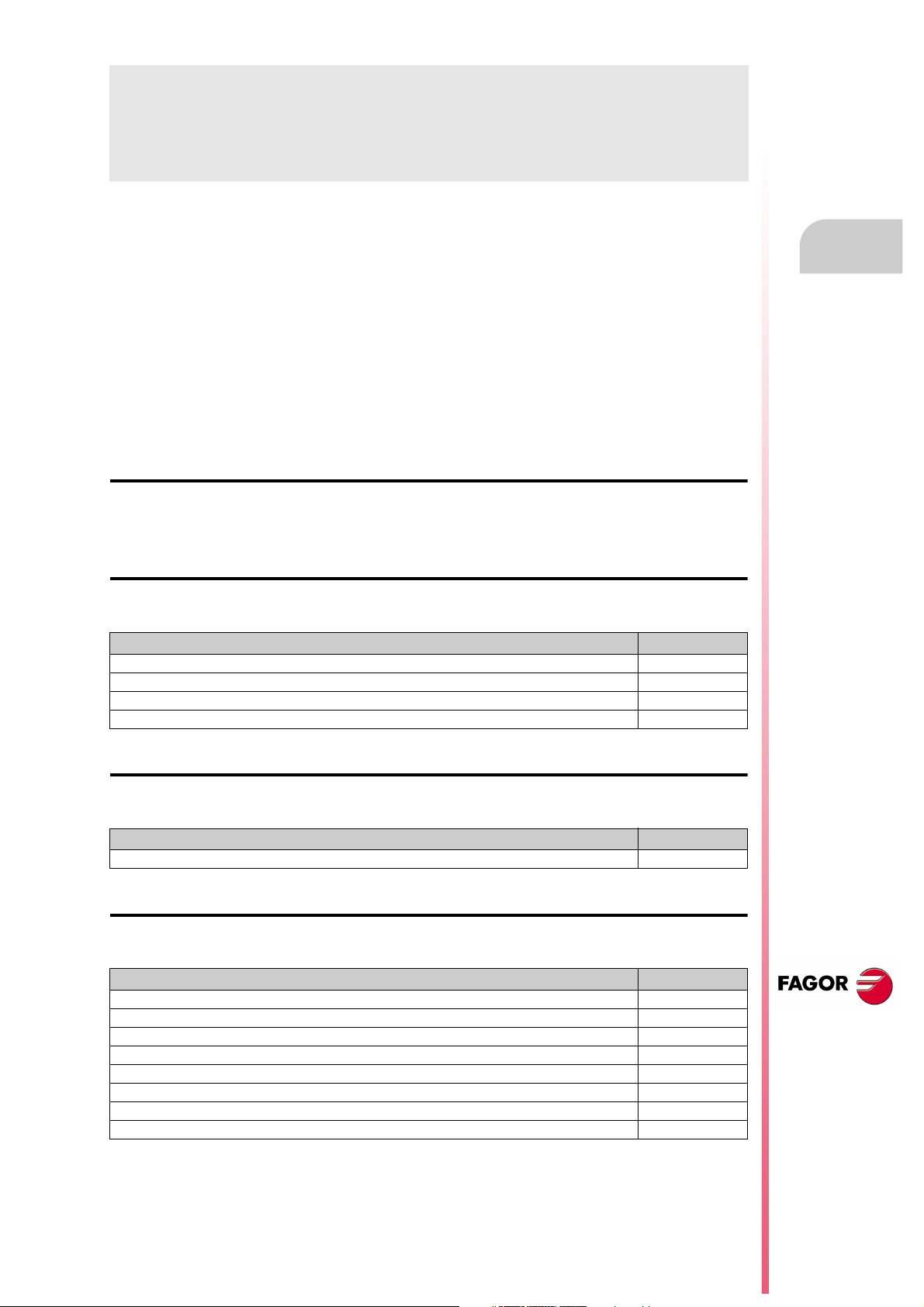
VERSION HISTORY
Here is a list of the features added in each software version and the manuals that describe them.
The version history uses the following abbreviations:
INST Installation manual
PRG Programming manual
OPT Operating manual
OPT-MC Operating manual for the MC option.
OPT-TC Operating manual for the TC option.
OPT-CO Manual of the CO manual
Software V01.00 October 2010
First version.
Software V01.20 April 2011
List of features Manual
Open communication. INST
Improvements to Look Ahead machining. INST
Blocks with helical interpolation in G51. PRG
G84. Tapping with relief. PRG
Software V01.08 August 2011
List of features Manual
S.m.p. OPLDECTI (P86). INST
Software V01.30 September 2011
List of features Manual
Gear ratio management on Sercos spindles INST
Improved feedrate limit management (FLIMIT). INST
New type of penetration in lathe type threading cycles. PRG
Improved lathe type thread repair. Partial repair. PRG
MC option: Rigid tapping with relief. OPT-MC
TC option: New type of penetration in threading cycles. OPT-TC
TC option: Improved thread repair. Partial and multi-entry (start) thread repair. OPT-TC
TC option: Zig-zag entry to the groove at the starting point of the groove. OPT-TC
CNC 8055
CNC 8055i
·11·
Page 12
Version history
Software V01.31 October 2011
List of features Manual
CNC 8055 FL Engraving model INST / OPT/ PRG
Software V01.40 January 2012
List of features Manual
Execution of M3, M4 and M5 using PLC marks INST / PRG
Values 12 and 43 of variable OPMODE in conversational work mode. INST
CNC 8055
CNC 8055i
·12·
Page 13
SAFETY CONDITIONS
Read the following safety measures in order to prevent harming people or damage to this product and those
products connected to it.
This unit may only be repaired by authorized personnel at Fagor Automation.
Fagor Automation shall not be held responsible of any physical damage or defective unit resulting from not
complying with these basic safety regulations.
PRECAUTIONS AGAINST PERSONAL DAMAGE
• Interconnection of modules.
Use the connection cables provided with the unit.
• Use proper Mains AC power cables
To avoid risks, use only the Mains AC cables recommended for this unit.
• Avoid electrical overloads.
In order to avoid electrical discharges and fire hazards, do not apply electrical voltage outside the range
selected on the rear panel of the central unit.
• Ground connection.
In order to avoid electrical discharges, connect the ground terminals of all the modules to the main
ground terminal. Before connecting the inputs and outputs of this unit, make sure that all the grounding
connections are properly made.
• Before powering the unit up, make sure that it is connected to ground.
In order to avoid electrical discharges, make sure that all the grounding connections are properly made.
• Do not work in humid environments.
In order to avoid electrical discharges, always work under 90% of relative humidity (non-condensing)
and 45 ºC (113º F).
• Do not work in explosive environments.
In order to avoid risks or damages, do no work in explosive environments.
CNC 8055
CNC 8055i
·13·
Page 14
CNC 8055
CNC 8055i
• Working environment.
This unit is ready to be used in industrial environments complying with the directives and regulations
effective in the European Community.
Fagor Automation shall not be held responsible for any damage suffered or caused when installed in
other environments (residential or homes).
• Install this unit in the proper place.
It is recommended, whenever possible, to install the CNC away from coolants, chemical product, blows,
etc. that could damage it.
This unit complies with the European directives on electromagnetic compatibility. Nevertheless, it is
recommended to keep it away from sources of electromagnetic disturbance such as:
Powerful loads connected to the same AC power line as this equipment.
Safety conditions
Nearby portable transmitters (Radio-telephones, Ham radio transmitters).
Nearby radio/TV transmitters.
Nearby arc welding machines.
Nearby High Voltage power lines.
Etc.
•Enclosures.
The manufacturer is responsible of assuring that the enclosure involving the equipment meets all the
currently effective directives of the European Community.
• Avoid disturbances coming from the machine tool.
The machine-tool must have all the interference generating elements (relay coils, contactors, motors,
etc.) uncoupled.
DC relay coils. Diode type 1N4000.
AC relay coils. RC connected as close to the coils as possible with approximate values of R=220
AC motors. RC connected between phases, with values of R=300 / 6 W y C=0,47 µF / 600 V.
• Use the proper power supply.
Use an external regulated 24 Vdc power supply for the inputs and outputs.
• Grounding of the power supply.
The zero volt point of the external power supply must be connected to the main ground point of the
machine.
• Analog inputs and outputs connection.
It is recommended to connect them using shielded cables and connecting their shields (mesh) to the
corresponding pin.
• Ambient conditions.
The working temperature must be between +5 ºC and +40 ºC (41ºF and 104º F)
The storage temperature must be between -25 ºC and +70 ºC. (-13 ºF and 158 ºF)
• Monitor enclosure (CNC 8055) or central unit ( CNC 8055i)
Guarantee the required gaps between the monitor or the central unit and each wall of the enclosure.
Use a DC fan to improve enclosure ventilation.
• Power switch.
This power switch must be mounted in such a way that it is easily accessed and at a distance between
0.7 meters (27.5 inches) and 1.7 meters (5.5ft) off the floor.
PRECAUTIONS AGAINST PRODUCT DAMAGE
1 W y C=0,2 µF / 600 V.
·14·
Page 15
PROTECTIONS OF THE UNIT ITSELF (8055)
OUT
IN
X7
X1
X8
X9
X2
X10
X3
X11X4X12
X5
X13
X6
+24V
0V
FUSIBLE
FUSE
• "Axes" and "Inputs-Outputs" modules.
All the digital inputs and outputs have galvanic isolation via optocouplers between the CNC circuitry
and the outside.
They are protected by an external fast fuse (F) of 3.15 A 250V against overvoltage of the external power
supply (over 33 Vdc) and against reverse connection of the power supply.
• Monitor.
The type of protection fuse depends on the type of monitor. See identification label of the unit itself.
PROTECTIONS OF THE UNIT ITSELF (8055I)
• Central Unit.
It has a 4 A 250V external fast fuse (F).
• Inputs-Outputs.
All the digital inputs and outputs have galvanic isolation via optocouplers between the CNC circuitry
and the outside.
Safety conditions
CNC 8055
CNC 8055i
·15·
Page 16
PRECAUTIONS DURING REPAIR
i
Do not get into the inside of the unit. Only personnel authorized by Fagor Automation may manipulate
the inside of this unit.
Do not handle the connectors with the unit connected to main AC power. Before manipulating the
connectors (inputs/outputs, feedback, etc.) make sure that the unit is not connected to AC power.
SAFETY SYMBOLS
Safety conditions
• Symbols which may appear on the manual.
Symbol for danger or prohibition.
It indicates actions or operations that may cause damage to people or to units.
Warning symbol.
It indicates situations that may be caused by certain operations and the actions to be taken to prevent
them.
Obligation symbol.
It indicates actions and operations that must be carried out.
Information symbol.
It indicates notes, warnings and advises.
CNC 8055
CNC 8055i
·16·
Page 17

WARRANTY TERMS
INITIAL WARRANTY
All products manufactured or marketed by FAGOR carry a 12-month warranty for the end user which could
be controlled by the our service network by means of the warranty control system established by FAGOR
for this purpose.
In order to prevent the possibility of having the time period from the time a product leaves our warehouse
until the end user actually receives it run against this 12-month warranty, FAGOR has set up a warranty
control system based on having the manufacturer or agent inform FAGOR of the destination, identification
and on-machine installation date, by filling out the document accompanying each FAGOR product in the
warranty envelope. This system, besides assuring a full year of warranty to the end user, enables our service
network to know about FAGOR equipment coming from other countries into their area of responsibility.
The warranty starting date will be the one appearing as the installation date on the above mentioned
document. FAGOR offers the manufacturer or agent 12 months to sell and install the product. This means
that the warranty starting date may be up to one year after the product has left our warehouse so long as
the warranty control sheet has been sent back to us. This translates into the extension of warranty period
to two years since the product left our warehouse. If this sheet has not been sent to us, the warranty period
ends 15 months from when the product left our warehouse.
This warranty covers all costs of material and labour involved in repairs at FAGOR carried out to correct
malfunctions in the equipment. FAGOR under takes to repair or replace their products within the period from
the moment manufacture begins until 8 years after the date on which it disappears from the catalog.
FAGOR has exclusive competence in deciding whether the repair enters within the term defined as the
warranty period.
EXCLUDING CLAUSES
Repairs will be carried out on our premises. Therefore, all expenses incurred as a result of trips made by
technical personnel to carry out equipment repairs, despite these being within the above-mentioned period
of warranty, are not covered by the warranty.
Said warranty will be applied whenever the equipment has been installed in accordance with instructions,
has not be mistreated, has not been damaged by accident or by negligence and has not been tampered
with by personnel not authorized by FAGOR. If, once servicing or repairs have been made, the cause of
the malfunction cannot be attributed to said elements, the customer is obliged to cover the expenses
incurred, in accordance with the tariffs in force.
Other warranties, implicit or explicit, are not covered and FAGOR AUTOMATION cannot be held responsible
for other damages which may occur.
CNC 8055
CNC 8055i
·17·
Page 18
WARRANTY ON REPAIRS
In a similar way to the initial warranty, FAGOR offers a warranty on standard repairs according to the
following conditions:
PERIOD
CONCEPT
EXCLUDING CLAUSES
When the customer does not choose the standard repair and just the faulty material has been replaced,
Warranty terms
the warranty will cover just the replaced parts or components within 12 months.
For sold parts the warranty is 12 moths length.
The SERVICE CONTRACT is available for the distributor or manufacturer who buys and installs our CNC
systems.
12 months.
Covers parts and labor for repairs (or replacements) at the network's own
facilities.
The same as those applied regarding the chapter on initial warranty.
If the repair is carried out within the warranty period, the warranty extension
has no effect.
MAINTENANCE CONTRACTS
CNC 8055
CNC 8055i
·18·
Page 19

MATERIAL RETURNING TERMS
When sending the central nit or the remote modules, pack them in its original package and packaging
material. If the original packaging material is not available, pack it as follows:
1. Get a cardboard box whose three inside dimensions are at least 15 cm (6 inches) larger than those
of the unit. The cardboard being used to make the box must have a resistance of 170 kg. (375 pounds).
2. Attach a label indicating the owner of the unit, person to contact, type of unit and serial number.
3. In case of failure, also indicate the symptom and a short description.
4. Wrap the unit in a polyethylene roll or similar material to protect it.
5. When sending the central unit, protect especially the screen.
6. Pad the unit inside the cardboard box with polyurethane foam on all sides.
7. Seal the cardboard box with packing tape or industrial staples.
CNC 8055
CNC 8055i
·19·
Page 20

Material returning terms
CNC 8055
CNC 8055i
·20·
Page 21

ADDITIONAL REMARKS
FAGOR
I/O
X1
X2
X3
AXES
X1 X2
X3 X4
X5 X6
X7 X8
X9
X10
CPU
X1 X2
CMPCT
FLASH
ETH
COM1
X3
C
D
E
F
0
B
A
9
8
1
7
2
6
3
5
4
IN
OUT
NODE
USB
(A)
(B)
X1
W1
Mount the CNC away from coolants, chemical products, blows, etc. which could damage it. Before turning
the unit on, verify that the ground connections have been properly made.
To prevent electrical shock at the central unit of the 8055 CNC, use the proper mains AC connector at the
power supply module. Use 3-wire power cables (one for ground connection).
To prevent electrical shock at the monitor of the 8055 CNC, use the proper mains AC connector (A) with
3-wire power cables (one of them for ground connection).
Before turning on the monitor of the 8055 CNC and verifying that the external AC line (B) fuse of each unit
is the right one. See identification label of the unit itself.
In case of a malfunction or failure, disconnect it and call the technical service. Do not get into the inside
of the unit.
CNC 8055
CNC 8055i
·21·
Page 22

Additional remarks
CNC 8055
CNC 8055i
·22·
Page 23

FAGOR DOCUMENTATION
OEM manual
It is directed to the machine builder or person in charge of installing and starting-up the CNC.
USER-M manual
Directed to the end user.
It describes how to operate and program in M mode.
USER-T manual
Directed to the end user.
It describes how to operate and program in T mode.
MC Manual
Directed to the end user.
It describes how to operate and program in MC mode.
It contains a self-teaching manual.
TC Manual
Directed to the end user.
It describes how to operate and program in TC mode.
It contains a self-teaching manual.
MCO/TCO model
Directed to the end user.
It describes how to operate and program in MCO and TCO mode.
Examples-M manual
Directed to the end user.
It contains programming examples for the M mode.
Examples-T manual
Directed to the end user.
It contains programming examples for the T mode.
WINDNC Manual
It is directed to people using the optional DNC communications software.
It is supplied in a floppy disk with the application.
WINDRAW55 Manual
Directed to people who use the WINDRAW55 to create screens.
It is supplied in a floppy disk with the application.
CNC 8055
CNC 8055i
·23·
Page 24

Fagor documentation
CNC 8055
CNC 8055i
·24·
Page 25
GENERAL CONCEPTS
1
The CNC may be programmed at the machine (from the front panel) and from a peripheral
(computer). Memory available to the user for carrying out the part programs is 1 Mbyte.
The part programs and the values in the tables which the CNC has can be entered from the front
panel, from a pc (DNC) or from a peripheral.
Entering programs and tables from the front panel.
Once the editing mode or desired table has been selected, the CNC allows you to enter data from
the keyboard.
Entering programs and tables from a Computer (DNC) or peripheral device.
The CNC allows data to be exchanged with a computer or peripheral device, using the RS232C serial
line.
If this is controlled from the CNC, it is necessary to preset the corresponding table or part program
directory (utilities) you want to communicate with.
Depending on the type of communication required, the ser ial port machine parameter "PROTOCOL"
should be set.
"PROTOCOL" = 0 If the communication is with a peripheral device.
"PROTOCOL" = 1 If the communication is via DNC.
CNC 8055
CNC 8055i
·T· MODEL
SOFT: V01.4X
·25·
Page 26

1.
1.1 Part programs
Part programs
Programming manual
The operating manual describes the different operating modes. Refer to that manual for further
information.
Editing a part-program
To create a part-program, access the –Edit– mode.
The new part-program edited is stored in the CNC's RAM memory. A copy of the part-programs may
be stored in the hard disk (KeyCF) at a PC connected through the serial line or in the USB disk.
To transmit a program to a PC through the serial, proceed as follows:
1. Execute the "WinDNC.exe" application program at the PC.
2. Activate DNC communications at the CNC.
3. Select the work directory at the CNC. It is selected from the –Utilities– mode, option Directory
\Serial L \Change directory
GENERAL CONCEPTS
In –Edit– mode, it is possible to modify part-programs residing in the CNC's RAM memory. To modify
a program stored in the hard disk (KeyCF), in a PC or in the USB disk, it must be previously copied
into RAM memory.
Executing and editing a part-program
Part-programs stored anywhere may be executed or simulated. Simulation is carried out in the
–Simulation– mode, whereas the execution is done in the –Automatic– mode
When executing or simulating a part-program, bear in mind the following points:
• Only subroutines stored in the CNC's RAM memory can be executed. Therefore, to execute a
subroutine stored in the hard disk (KeyCF), in a PC or in the USB disk, it must be first copied
into the CNC's RAM memory.
• The GOTO and RPT instructions cannot be used in programs that are executed from a PC
connected through the serial line.
• From a program in execution, it is possible to execute another program located in RAM memory,
in the hard disk (KeyCF) or in a PC using the EXEC instruction.
The user customizing programs must be in RAM memory so the CNC can execute them.
–Utilities– operating mode.
CNC 8055
CNC 8055i
·T· MODEL
SOFT: V01.4X
·26·
The –Utilities– mode, lets display the part-program directory of all the devices, make copies, delete,
rename and even set the protections for any of them.
Page 27

Programming manual
Operations that may be carried out with part-programs.
See the program directory of ...
See the subroutine directory of ...
Create the work directory from ...
Change the work directory from ...
Edit a program from ...
Modify a program from ...
Delete a program from ...
Copy from/to RAM memory to/from ...
Copy from/to HD to/from ...
Copy from/to DNC to/from ...
Rename a program from ...
Change the comment of a program from ...
Change the protections of a program from ...
Execute a part-program from ...
Execute a user program from ...
Execute a PLC program from ...
Execute programs with GOTO or RPT instructions from ...
Execute subroutines residing in ...
Execute programs with the EXEC instruction, in RAM from ...
Execute programs with the EXEC instruction, in HD from ...
Execute programs with the EXEC instruction, in DNC from ...
RAM
memory
Ye s
Ye s
No
No
Ye s
Ye s
Ye s
Ye s
Ye s
Ye s
Ye s
Ye s
Ye s
Ye s
Ye s
Ye s
Ye s
Ye s
Ye s
Ye s
Ye s
Hard
disk
Ye s
No
No
No
Ye s
Ye s
Ye s
Ye s
Ye s
Ye s
Ye s
Ye s
Ye s
Ye s
Ye s
No
Ye s
No
Ye s
Ye s
Ye s
DNC
Ye s
No
No
Ye s
No
No
Ye s
Ye s
Ye s
Ye s
No
No
No
Ye s
No
No
No
No
Ye s
Ye s
No
1.
Part programs
GENERAL CONCEPTS
Open programs with the OPEN instruction, in RAM from ...
Open programs with the OPEN instruction, in HD from ...
Open programs with the OPEN instruction, in DNC from ...
Via Ethernet:
See from a PC the program directory of ...
See from a PC the subroutine directory of ...
See from a PC, a directory in ...
Ye s
Ye s
Ye s
No
No
No
Ye s
Ye s
Ye s
Ye s
No
No
(*) If it is not in RAM memory, it generates the executable code in RAM and it executes it.
Ethernet
When having the Ethernet option and if the CNC is configured as another node within the computer
network, the following operations are possible from any PC of the network:
• Access the part-program directory of the hard disk (KeyCF).
• Edit, modify, delete, rename, etc. the programs stored on the hard disk.
• Copy programs from the hard disk to the PC and vice versa.
To configure the CNC as another node within the computer network, see the installation manual.
Ye s
Ye s
No
No
No
No
CNC 8055
CNC 8055i
·T· MODEL
SOFT: V01.4X
·27·
Page 28

1.
Part programs
GENERAL CONCEPTS
Programming manual
1.1.1 Considerations regarding the Ethernet connection
When configuring the CNC as another node in the computer network, the programs stored in the
hard disk (KeyCF) may be edited and modified from any PC.
Instructions for setting up a PC to access CNC directories
To set up the PC to access the CNC directories, we recommend to proceed as follows.
1. Open the "Windows Explorer"
2. On the "Tools" menu, select the "Connect to Network Drives" option.
3. Select the drive, for example "D".
4. Indicate the path. The path will be the CNC name followed by the name of the shared directory.
For example: \\FAGORCNC\CNCHD
5. When selecting the option: "Connect again when initiating the session", the selected CNC will
appear on each power-up as another path of the "Windows Explorer" without having to define
it again.
Data format
This connection is established through Ethernet and, therefore, the CNC does not control the syntax
of the programs while they are received or modified. However, whenever accessing the program
directory of the Hard Disk (HD), the following verification takes place:
File name.
The file number must always have 6 digits and the extension PIM (for milling) or PIT (for lathe).
Examples: 001204.PIM 000100.PIM 123456.PIT 020150.PIT
If the file has been given the wrong name, for example: 1204.PIM or 100.PIT, the CNC will not change
it, but it will display it with the comment "****************". The file name cannot be modified
at the CNC; it must be edited from the PC to correct the error.
File size.
If the file is empty (size = 0) the CNC will display it with the comment "********************".
The file can be edited or deleted either from the CNC or from the PC.
First line of the program.
The first line of the program must have the % character, the comment associated with the file (up
to 20 characters) and between the two commas (,) the program attributes O (OEM), H (hidden), M
(modifiable), X (executable).
Examples: %Comment ,MX,
% ,OMX,
CNC 8055
CNC 8055i
·T· MODEL
SOFT: V01.4X
·28·
If the first line does not exist, the CNC will display the program with an empty comment and with
the modifiable (M) and executable (X) attributes.
When the format of the first line is wrong, the CNC does not modify it, but it displays it with the
comment "****************". The file can be edited or deleted either from the CNC or from the
PC.
The format is incorrect when the comment has more than 20 characters, a comma (,) is missing
to group the attributes or there is a strange character in the attributes.
Page 29

Programming manual
1.2 DNC connection
The CNC offers as optional feature the possibility of working in DNC (Distributed Numerical Control),
enabling communication between the CNC and a computer to carry out the following functions:
• Directory and delete commands.
• Transfer of programs and tables between the CNC and a computer.
• Remote control of the machine.
• The ability to supervise the status of advanced DNC systems.
1.
DNC connection
GENERAL CONCEPTS
CNC 8055
CNC 8055i
·T· MODEL
SOFT: V01.4X
·29·
Page 30

1.
GENERAL CONCEPTS
Communication protocol via DNC or peripheral device
Programming manual
1.3 Communication protocol via DNC or peripheral device
This type of communication enables program-and-table transfer commands, plus the organization
of CNC directories such as the computer directory, for copying/deleting programs, etc. to be done
either from the CNC or the computer.
When you want to transfer files, it is necessary to follow this protocol:
• The "%" symbol will be used to start the file, followed by the program comment (optional), of up
to 20 characters.
Then, and separated by a comma ",", comes the protection of each file, read, write, etc. These
protections are optional and need not be programmed.
To end the file header, RT (RETURN ) or LF (LINE FEED) characters should be sent separated
by a comma (",").
Example: %Fagor Automation, MX, RT
• Following the header, the file blocks should be programmed. These will all be programmed
according to the programming rules indicated in this manual. After each block, to separate it from
the others, the RT (RETURN ) or LF (LINE FEED) characters should be used.
Example: N20 G90 G01 X100 Y200 F2000 LF
(RPT N10, N20) N3 LF
If communication is made with a peripheral device, you will need to send the ‘end of file’ command.
This command is selected via the machine parameter for the serial port: "EOFCHR", and can be
one of the following characters :
ESC ESCAPE
EOT END OF TRANSMISSION
SUB SUBSTITUTE
EXT END OF TRANSMISSION
CNC 8055
CNC 8055i
·T· MODEL
SOFT: V01.4X
·30·
Page 31

CREATING A PROGRAM
2
A CNC program consists of a series of blocks or instructions. These blocks or instructions are made
of words composed of capital letters and numerical format.
The CNC’s numerical format consists of :
• The signs . (decimal points, + (plus), - (minus).
• Digits 0 1 2 3 4 5 6 7 8 9.
Programming allows spaces between letters, numbers and symbols, in addition to ignoring the
numerical format if it has zero value, or a symbol if it is positive.
The numeric format of a word may be replaced by an arithmetic parameter when programming. Later
on, during execution, the CNC will replace the arithmetic parameter by its value. For example, if XP3
has been programmed, during execution the CNC will replace P3 by its numerical value, obtaining
results such as X20, X20.567, X-0.003, etc.
CNC 8055
CNC 8055i
·T· MODEL
SOFT: V01.4X
·31·
Page 32

2.
Programming manual
2.1 Program structure at the CNC
All the blocks which make up the program have the following structure:
Block header + program block + end of block
2.1.1 Block header
The block header is optional, and may consist of one or more block skip conditions and by the block
number or label. Both must be programmed in this order.
Block skip condition. "/", "/1", "/2", "/3".
These three block skip conditions, given that "/" and "/1" are the same, they are governed by the
marks BLKSKIP1, BLKSKIP2 and BLKSKIP3 of the PLC. If any of these marks is active, the CNC
will not execute the block or blocks in which it has been programmed; the execution takes place in
the following block.
CREATING A PROGRAM
Program structure at the CNC
Up to 3 skip conditions can be programmed in one block; they will be evaluated one by one,
respecting the order in which they have been programmed.
The control reads 200 blocks ahead of the one being executed in order to calculate in advance the
path to be run. The condition for block skip will be analyzed at the time when the block is read i.e.
200 blocks before execution.
If the block skip needs to be analyzed at the time of execution, it is necessary to interrupt the block
preparation, by programming G4 in the previous block.
Label or block number. N(0-99999999).
This is used to identify the block, and is only used when block references or jumps are made. They
are represented by the letter N followed by up to 8 digits (0-99999999).
No particular order is required and the numbers need not be sequential. If two or more blocks with
the same label number are present in the same program, the CNC will always give priority to the
first number.
Although it is not necessary to program it, by using a softkey the CNC allows the automatic
programming of labels. The programmer can select the initial number and the step between labels.
Restrictions:
• Displaying the number of the active block in the top window of the screen:
When executing a program in ISO mode, when the label number is higher than 9999, it
displays N**** .
On the "DISPLAY / SUBROUTINES" window, when displaying an RPT that has a label higher
than 9999, it displays it with ****.
• Canned cycles G66, G68 and G69 can only be edited using 4-digit labels.
CNC 8055
CNC 8055i
·T· MODEL
SOFT: V01.4X
·32·
Page 33

Programming manual
2.1.2 Program block
This is written with commands in ISO and high level languages. To prepare a program, blocks written
in both languages will be used, although each one should be edited with commands in just one
language.
ISO language
This language is specially designed to control axis movement, as it gives information and movement
conditions, in addition to data on feedrate. It offers the following types of functions.
• Preparatory functions for movement, used to determine geometry and working conditions, such
as linear and circular interpolations, threading, etc.
• Control functions for axis feedrate and spindle speeds.
• Tool control functions.
• Complementary functions, with technological instructions.
High level language
This enables access to general purpose variables and to system tables and variables.
2.
It gives the user a number of control sentences which are similar to the terminology used in other
languages, such as IF, GOTO, CALL, etc. It also allows the use of any type of expression (arithmetic,
referential, or logical).
It also has instructions for the construction of loops, plus subroutines with local variables. A local
variable is one that is only recognized by the subroutine in which it has been defined.
It is also possible to create libraries, grouping subroutines with useful and tested functions, which
can be accessed from any program.
CREATING A PROGRAM
Program structure at the CNC
CNC 8055
CNC 8055i
·T· MODEL
SOFT: V01.4X
·33·
Page 34

Programming manual
2.1.3 End of block
The end of block is optional and may consist of the indication of number of repetitions of the block
and of the block comment. Both must be programmed in this order.
Number of block repetitions. N(0-9999)
This indicates the number of times the block will be executed. The number of repetitions is
represented by the letter N followed by up to 4 digits (0-9999). The active machining operation does
not take place if N0 is programmed; only the movement programmed within the block takes place.
2.
CREATING A PROGRAM
Program structure at the CNC
Movement blocks can only be repeated which, at the time of their execution, are under the influence
of a modal subroutine. In these cases, the CNC executes the programmed move and the active
machining operation (canned cycle or modal subroutine) the indicated number of times.
Block comment
The CNC allows you to incorporate any kind of information into all blocks in the form of a comment.
The comment is programmed at the end of the block, and should begin with the character ";"
(semicolon).
If a block begins with ";" all its contents will be considered as a comment, and it will not be executed.
Empty blocks are not permitted. They should contain at least one comment.
CNC 8055
CNC 8055i
·T· MODEL
SOFT: V01.4X
·34·
Page 35

AXES AND COORDINATE SYSTEMS
3
Given that the purpose of the CNC is to control the movement and positioning of axes, it is necessary
to determine the position of the point to be reached through its coordinates.
The CNC allows you to use absolute, relative or incremental coordinates throughout the same
program.
CNC 8055
CNC 8055i
·T· MODEL
SOFT: V01.4X
·35·
Page 36

3.
Programming manual
3.1 Axis nomenclature
The axes are named according to DIN 66217.
Axis nomenclature
AXES AND COORDINATE SYSTEMS
Characteristics of the system of axes:
X and Y main movements on the main work plane of the machine.
Z parallel to the main axis of the machine, perpendicular to the main XY plane.
U, V, W auxiliary axes parallel to X, Y, Z respectively.
A B C Rotary axes on each axis X, Y, Z.
The drawing below shows an example of the nomenclature of the axes on a parallel lathe.
CNC 8055
CNC 8055i
·T· MODEL
SOFT: V01.4X
·36·
Page 37

Programming manual
3.1.1 Axis selection
Of the 9 possible axes that may exist, the CNC allows the manufacturer to select up to 7 of them.
Moreover, all the axes should be suitably defined as linear/rotary, etc. through the axis machine
parameters which appear in the Installation and Start-up Manual.
There is no limitation to the programming of the axes, and up to 7 axes may be interpolated at the
same time.
3.
Axis nomenclature
AXES AND COORDINATE SYSTEMS
CNC 8055
CNC 8055i
·T· MODEL
SOFT: V01.4X
·37·
Page 38

3.
Programming manual
3.2 Plane selection (G16, G17, G18, G19)
Plane selection should be made when the following are carried out :
• Circular interpolations.
• Controlled corner rounding.
• Tangential entry and exit.
•Chamfer.
• Coordinate programming in Polar coordinates.
• Pattern rotation.
• Tool radius Compensation.
• Tool length compensation.
The "G" functions which enable selection of work planes are as follows :
G16 axis1 axis2. Enables selection of the desired work plane, plus the direction of G02 G03
(circular interpolation), axis1 being programmed as the abscissa axis and
axis2 as the ordinate axis.
Plane selection (G16, G17, G18, G19)
AXES AND COORDINATE SYSTEMS
G17. Selects the XY plane.
G18. Selects the ZX plane.
G19. Selects the YZ plane.
The G16, G17, G18 and G19 functions are modal and incompatible among themselves. The G16
function should be programmed on its own within a block.
CNC 8055
CNC 8055i
·T· MODEL
SOFT: V01.4X
·38·
On power-up, after executing M02, M30 or after EMERGENCY or RESET, the CNC will assume that
the plane defined by the general machine parameter as "IPLANE" is the work plane.
Page 39

Programming manual
3.3 Part dimensioning. Millimeters (G71) or inches (G70)
The CNC allows you to enter units of measurement with the programming, either in millimeters or
inches.
It has a general machine parameter "INCHES" to define the unit of measurement of the CNC.
However, these units of measurement can be changed at any time in the program. Two functions
are supplied for this purpose :
• G70. Programming in inches.
• G71. Programming in millimeters.
Depending on whether G70 or G71 has been programmed, the CNC assumes the corresponding
set of units for all the blocks programmed from that moment on.
The G70 and G71 functions are modal and are incompatible.
The CNC allows you to program figures from 0.00001 to 99999.9999 with or without sign, working
in millimeters (G71), called format +/-5.4, or either from 0.00001 to 3937.00787 with or without sign
if the programming is done in inches (G70), called format +/-4.5.
However, and to simplify the instructions, we can say that the CNC admits +/- 5.5 format, thereby
admitting +/- 5.4 in millimeters and +/- 4.5 in inches.
On power-up, after executing M02, M30 or after EMERGENCY or RESET, the CNC will assume that
the system of units of measurement is the one defined by the general machine parameter "INCHES".
3.
AXES AND COORDINATE SYSTEMS
Part dimensioning. Millimeters (G71) or inches (G70)
CNC 8055
CNC 8055i
·T· MODEL
SOFT: V01.4X
·39·
Page 40

3.
Absolute coordinates:
G90 X200 Z60 ; Point P0
X160 Z60 ; Point P1
X80 Z100 ; Point P2
X80 Z120 ; Point P3
Incremental coordinates:
G90 X200 Z60 ; Point P0
G91 X-40 ; Point P1
X-80 Z40 ; Point P2
Z20 ; Point P3
Example programming the X axis in diameter.
Programming manual
3.4 Absolute/incremental programming (G90, G91)
The CNC allows the programming of the coordinates of one point either with absolute G90 or
incremental G91 values.
When working with absolute coordinates (G90), the point coordinates refer to a point of origin of
established coordinates, often the part zero (datum).
When working in incremental coordinates (G91), the numerical value programmed corresponds to
the movement information for the distance to be traveled from the point where the tool is situated
at that time. The sign in front shows the direction of movement.
The G90/G91 functions are modal and incompatible with each other.
AXES AND COORDINATE SYSTEMS
Absolute/incremental programming (G90, G91)
On power-up, after executing M02, M30 or after an EMERGENCY or RESET, the CNC will assume
G90 or G91 according to the definition by the general machine parameter "ISYSTEM".
CNC 8055
CNC 8055i
·T· MODEL
SOFT: V01.4X
·40·
Page 41

Programming manual
3.5 Programming in radius or in diameters (G152, G151)
The X axis coordinates may be programmed in radius or diameter. The following functions may be
used for that.
• G151. Programming the X axis in diameter.
• G152. Programming the X axis in radius.
It is carried out by interpolating the main spindle (that is turning) with the Z axis. After the execution
of one of these functions, the CNC assumes the relevant programming mode for the blocks
programmed afterwards.
The change of units is also taken into account in the following cases.
• Displaying the real X value of in the part's coordinate system.
• Reading of the variable PPOSX (programmed coordinate).
Functions G151 and G152 are modal and incompatible with each other.
On power-up, after executing an M02, M30 or after an emergency or reset, the CNC assumes G151
or G152 depending on the setting of X axis machine parameter "DFORMAT".
3.
AXES AND COORDINATE SYSTEMS
Programming in radius or in diameters (G152, G151)
CNC 8055
CNC 8055i
·T· MODEL
SOFT: V01.4X
·41·
Page 42

3.
Programming manual
3.6 Coordinate programming
The CNC allows the selection of up to 7 of the 9 possible axes X, Y, Z, U, V, W, A, B, C.
Each of these may be linear, linear to position only, normal rotary, rotary to position only or rotary
with hirth toothing (positioning in complete degrees), according to the specification in the machine
parameter of each "AXISTYPE" axis.
With the aim of always selecting the most suitable coordinate programming system, the CNC has
the following types :
• Cartesian coordinates
• Polar coordinates
• Angle and Cartesian coordinate
Coordinate programming
AXES AND COORDINATE SYSTEMS
CNC 8055
CNC 8055i
·T· MODEL
SOFT: V01.4X
·42·
Page 43

Programming manual
3.6.1 Cartesian coordinates
The Cartesian Coordinate System is defined by two axes on the plane, and by three or more axes
in space.
The origin of all these, which in the case of the axes X Y Z coincides with the point of intersection,
is called Cartesian Origin or Zero Point of the Coordinate System.
The position of the different points of the machine is expressed in terms of the coordinates of the
axes, with two, three, four, or five coordinates.
The coordinates of the axes are programmed via the letter o f t h e a x is ( X, Y, Z , U, V, W , A , B, C, a lw ay s
in this order) followed by the coordinate value.
The values of the coordinates are absolute or incremental, depending on whether it is working in
G90 or G91, and its programming format is ±5.5.
3.
Coordinate programming
AXES AND COORDINATE SYSTEMS
CNC 8055
CNC 8055i
·T· MODEL
SOFT: V01.4X
·43·
Page 44

3.
Programming manual
3.6.2 Polar coordinates
In the event of the presence of circular elements or angular dimensions, the coordinates of the
different points on the plane (2 axes at the same time), it may be easier to express them in polar
coordinates.
The reference point is called Polar Origin, and this will be the origin of the Polar Coordinate System.
A point on this system would be defined by :
Coordinate programming
• The RADIUS (R), the distance between the polar origin and the point.
• The ANGLE (Q), formed by the abscissa axis and the line which joins the polar origin with the
point. (In degrees).
AXES AND COORDINATE SYSTEMS
The values R and Q are absolute or incremental depending on whether you are working with G90
or G91, and their programming format will be R5.5 Q±5.5. The radius value must always be positive.
The values R and Q are incremental and their programming format will be R±5.5 Q±5.5.
The R values may be negative when programming in incremental coordinates; but the resulting value
assigned to the radius must always be positive.
When programming a "Q" value greater than 360º, the module will be assumed after dividing it by
360. Thus, Q420 is the same as Q60 and Q-420 is the same as Q-60.
Programming example assuming that the Polar Origin is located at the Coordinate Origin.
CNC 8055
CNC 8055i
·T· MODEL
SOFT: V01.4X
·44·
Page 45

Programming manual
Absolute coordinates:
G90 R430 Q0 ; Point P0
G03 Q33.7 ; Point P1, in an arc (G03)
G01 R340 Q45 ; Point P2, in a straight line (G01)
G01 R290 Q33.7 ; Point P3, in a straight line (G01)
G01 R230 Q45 ; Point P4, in a straight line (G01)
G01 R360 Q63.4 ; Point P5, in a straight line (G01)
G03 Q90 ; Point P6, in an arc (G03).
Incremental coordinates:
G90 R430 Q0 ; Point 0
G91 G03 Q33.7 ; Point P1, in an arc (G03)
G01 R-90 Q11.3 ; Point P2, in a straight line (G01)
G01 R-50 Q-11.3 ; Point P3, in a straight line (G01)
G01 R-60 Q11.3 ; Point P4, in a straight line (G01)
G01 R130 Q18.4 ; Point P5, in a straight line (G01)
G03 Q26.6 ; Point P6, in an arc (G03).
The polar origin, apart from being able to be preset using function G93 (described later) can be
modified in the following cases :
• On power-up, after executing M02, M30 EMERGENCY or RESET, the CNC will assume, as the
polar origin, the coordinate origin of the work plane defined by the general machine
parameter"IPLANE".
• Every time the work plane is changed (G16,G17,G18 or G19), the CNC assumes the coordinate
origin of the new work plane selected as the polar origin.
• When executing a circular interpolation (G02 or G03), and if the general machine parameter
"PORGMOVE" has a value of 1, the center of the arc will become the new polar origin.
3.
Coordinate programming
AXES AND COORDINATE SYSTEMS
CNC 8055
CNC 8055i
·T· MODEL
SOFT: V01.4X
·45·
Page 46

3.
Programming manual
3.6.3 Angle and Cartesian coordinate
A point on the main plane can be defined via one of its Cartesian coordinates, and the exit angle
of the previous path.
Example programming the X axis in radius.
Coordinate programming
AXES AND COORDINATE SYSTEMS
X0 Z160 ; Point P0
Q90 X30 ; Point P1
Q149 Z110 ; Point P2
Q180 Z80 ; Point P3
Q146.3 Z50 ; Point P4
Q90 X100 ; Point P0
If you wish to represent a point in space, the remaining coordinates can be programmed in Cartesian
coordinates.
CNC 8055
CNC 8055i
·T· MODEL
SOFT: V01.4X
·46·
Page 47

Programming manual
3.7 Rotary axes
The types of rotary axes available are:
Normal rotary axis.
Positioning-only rotary axis.
Rotary HIRTH axis.
Each one of them can be divided into:
Rollover When it is displayed between 0º and 360º.
Non Rollover When it may be displayed between -99999º and 99999º.
They are all programmed in degrees. Therefore, their readings are not affected by the inch/mm
conversion.
3.
Normal rotary axes
They can interpolate with linear axes.
Movement: In G00 and G01.
Rollover axis programming:
G90 The sign indicates the turning direction and the target position (between 0 and
359.9999).
G91 The sign indicates the turning direction. If the programmed movement exceeds
360º, the axis will rotate more than one turn before positioning at the desired point.
Non-rollover axis programming.
In G90 and G91 like a linear axis.
Positioning-only rotary axis
They cannot be interpolated with linear axes.
Movement: Always in G00 and they do not admit tool radius compensation (G41, G42).
Rollover axis programming:
G90 Always positive and in the shortest direction. End coordinate between 0 and
359.9999.
G91 The sign indicates the turning direction. If the programmed movement exceeds
360º, the axis will rotate more than one turn before positioning at the desired point.
Non-rollover axis programming.
In G90 and G91 like a linear axis.
Rotary axes
AXES AND COORDINATE SYSTEMS
Rotary Hirth axis
They work like the positioning-only axis except that they do not admit decimal position values
(coordinates).
More than one hirth axis can be used, but they can only be moved one at a time.
CNC 8055
CNC 8055i
·T· MODEL
SOFT: V01.4X
·47·
Page 48

Programming manual
G20 K1 X20 Z20
G21 K1 X100 Z100
3.8 Work zones
The CNC provides four work zones or areas, and also limits the tool movement in each of these.
3.8.1 Definition of the work zones
3.
Work zones
AXES AND COORDINATE SYSTEMS
Within each work zone, the CNC allows you to limit the movement of the tool on each axis, with upper
and lower limits being defined in each axis.
G20: Defines the lower limits in the desired zone.
G21: Defines the upper limits in the desired zone.
The format to program these functions is:
G20 K X...C±5.5
G21 K X...C±5.5
Where:
K Indicates the work zone you wish to define (1, 2, 3 or 4).
X...C Indicates the coordinates (upper or lower) with which you wish to limit the axes.
These coordinates are given in radius and must be programmed with reference
to machine zero (home). For safety, the axis stops 0.1mm before the programmed
limit.
It is not necessary to program all the axes, so only defined axes will be limited.
CNC 8055
CNC 8055i
·T· MODEL
SOFT: V01.4X
·48·
Page 49

Programming manual
S= 1 No entry zone S = 2 No exit zone
3.8.2 Using the work zones
Within each work zone, the CNC allows you to restrict the movement of the tool, either prohibiting
its exit from the programmed zone (no exit zone) or its entry into the programmed zone (no entry
zone).
The CNC will take the dimensions of the tool into account at all times (tool offset table) to avoid it
exceeding the programmed limits.
The presetting of work zones is done via Function G22, the programming format being:
G22 K S
3.
Work zones
Where:
K Indicates the work zone you wish to define (1, 2, 3 or 4).
S Indicates the enabling/disabling of the work zone.
S=0 disabled.
S=1 enabled as a no-entry zone.
S=2 enabled as a no-exit zone.
On power-up, the CNC will disable all work zones. However, upper and lower limits for these zones
will not undergo any variation, and they can be re-enabled through the G22 function.
AXES AND COORDINATE SYSTEMS
CNC 8055
CNC 8055i
·T· MODEL
SOFT: V01.4X
·49·
Page 50

3.
Programming manual
Work zones
AXES AND COORDINATE SYSTEMS
CNC 8055
CNC 8055i
·T· MODEL
SOFT: V01.4X
·50·
Page 51

REFERENCE SYSTEMS
M Machine zero
WPart zero
R Machine reference point
XMW, YMW, ZMW... Coordinates of part zero
XMR, YMR, ZMR... Coordinates of machine reference point ("REFVALUE")
4.1 Reference points
A CNC machine needs the following origin and reference points defined :
• Machine Reference Zero or home. This is set by the manufacturer as the origin of the coordinate
system of the machine.
• Part zero or point of origin of the part. This is the origin point that is set for programming the
measurements of the part. It can be freely selected by the programmer, and its machine
reference zero can be set by the zero offset.
• Machine Reference point. This is a point on the machine established by the manufacturer around
which the synchronization of the system is done. The control positions the axis on this point,
instead of moving it as far as the Machine Reference Zero, taking, at this point, the reference
coordinates which are defined via the axis machine parameter "REFVALUE".
4
CNC 8055
CNC 8055i
·T· MODEL
SOFT: V01.4X
·51·
Page 52

4.
4.2 Machine reference (Home) search (G74)
The CNC allows you to program the machine reference search in two ways :
• Machine reference (home) search of one or more axes in a particular order.
G74 is programmed followed by the axes in which you want to carry out the reference search.
For example: G74 X Z.
The CNC begins the movement of all the selected axes which have a machine reference switch
(machine axis parameter "DECINPUT") and in the direction indicated by the axis machine
parameter "REFDIREC".
This movement is carried out at the feedrate indicated by the axis machine parameter
"REFEED1" for each axis until the home switch is hit.
Next, the home search (marker pulse or home) will be carried out in the programmed order.
This second movement will be carried out one axis at a time, at the feedrate indicated in the axis
machine parameter "REFEED2" until the machine reference point is reached (i.e. the marker
pulse is found).
• Home search using the associated subroutine.
The G74 function will be programmed alone in the block, and the CNC will automatically execute
REFERENCE SYSTEMS
the subroutine whose number appears in the general machine parameter "REFPSUB". In this
subroutine it is possible to program the machine reference searches required, and also in the
required order.
In a block in which G74 has been programmed, no other preparatory function may appear.
Programming manual
If the machine reference search is done in JOG mode, the part zero selected is lost. The coordinates
Machine reference (Home) search (G74)
of the reference point indicated in the machine axis parameter "REFVALUE" is displayed. In all other
cases, the active part zero will be maintained and the CNC will display the position values with
respect to that part zero.
If the G74 command is executed in MDI, the display of coordinates depends on the mode in which
it is executed : Jog, Execution, or Simulation.
CNC 8055
CNC 8055i
·T· MODEL
SOFT: V01.4X
·52·
Page 53

Programming manual
M Machine zero
WPart zero
Example programming the X axis in diameter.
G90 G1 X40 Z30
G90 G53 G1 X140 Z100
4.3 Programming with respect to machine zero (G53)
Function G53 can be added to any block that has path control functions.
It is only used when the programming of block coordinates relating to machine zero is required.
These coordinates should be expressed in millimeters or inches, depending on how the general
machine parameter "INCHES" is defined.
By programming G53 alone (without motion information) the current active zero offset is canceled
regardless of whether it was originated by a G54-G59 or a G92 preset. This origin preset is described
next.
Function G53 is not modal, so it should be programmed every time you wish to indicate the
coordinates referred to machine zero.
This function temporarily cancels radius and tool length compensation.
4.
REFERENCE SYSTEMS
Programming with respect to machine zero (G53)
CNC 8055
CNC 8055i
·T· MODEL
SOFT: V01.4X
·53·
Page 54

4.
M Machine zero
WPart zero
Zero offsets
PLC Parameters.
G59
G58
G92
ORG*(59)
ORG*(58)
ORG*
PLCOF*
ORG*(54) ORG*(55) ORG*(56) ORG*(57)
G54 G55 G56 G57
Programming manual
4.4 Coordinate preset and zero offsets
The CNC allows you to carry out zero offsets with the aim of using coordinates related to the plane
of the part, without having to modify the coordinates of the different points of the part at the time
of programming.
The zero offset is defined as the distance between the part zero (point of origin of the part) and the
machine zero (point of origin of the machine).
REFERENCE SYSTEMS
Coordinate preset and zero offsets
This zero offset can be carried out in one of two ways :
• Via Function G92 (coordinate preset). The CNC accepts the coordinates of the programmed
axes after G92 as new axis values.
• Via the use of zero offsets (G54 ... G59, G159N1 ... G159N20); the CNC accepts as a new part
zero the point located relative to machine zero at the distance indicated by the selected table(s).
Both functions are modal and incompatible, so if one is selected the other is disabled.
There is, moreover, another zero offset which is governed by the PLC. This offset is always added
to the zero offset selected and is used (among other things) to correct deviations produced as a
result of expansion, etc.
CNC 8055
CNC 8055i
·T· MODEL
SOFT: V01.4X
·54·
Page 55

Programming manual
; Positioning in P0
G90 X0 Z200
; Preset P0 as part zero
G92 X0 Y0
; Programming according to part coordinates
G91 X30 Z-30
Z-30
X20
X20 Z-40
Z-30
4.4.1 Coordinate preset and S value limitation (G92)
Via Function G92 one can select any value in the axes of the CNC, in addition to limiting the spindle
speed.
• Coordinate preset.
When carrying out a zero offset via Function G92, the CNC assumes the coordinates of the axes
programmed after G92 as new axis values.
No other function can be programmed in the block where G92 is defined, the programming format
being :
G92 X...C ±5.5
The values assigned to the axes are programmed in either radius or diameter depending on the
setting of axis machine parameter "DFORMAT".
4.
REFERENCE SYSTEMS
• Spindle speed limitation
Programming "G92 S5.4", the CNC limits the spindle speed to the value set by S5.4.
This means that the CNC will not accept, from that block on, the programming of S values higher
than the maximum defined. Neither is it possible to exceed this maximum value from the
keyboard on the front panel.
Coordinate preset and zero offsets
CNC 8055
CNC 8055i
·T· MODEL
SOFT: V01.4X
·55·
Page 56

4.
4.4.2 Zero offsets (G54..G59 and G159)
The CNC has a table of zero offsets, in which several zero offsets can be selected. The aim is to
generate certain part zeros independently of the part zero active at the time. The table values are
given in radius.
Access to the table can be obtained from the front panel of the CNC (as explained in the Operating
Manual), or via the program using high-level language commands.
There are two kinds of zero offsets :
• Absolute zero offsets (G54 ... G57, G159N1 ... G159N20), which must be referred to machine
zero.
• Incremental zero offsets (G58,G59).
Functions G54, G55, G56, G57, G58 & G59 must be programmed alone in the block, and work in
the following way:
When one of the G54, G55, G56, G57 functions is executed, the CNC applies the zero offset
programmed with respect to machine zero, canceling the possible active zero offsets.
If one of the incremental offsets G58 or G59 is executed, the CNC adds its values to the absolute
zero offset active at the time. Previously canceling the additive offset which might be active.
REFERENCE SYSTEMS
Coordinate preset and zero offsets
You can see (in the following example) the zero offsets which are applied when the program is
executed.
G54 Applies zero offsets G54 ==> G54
G58 Adds zero offset G58 ==> G54+G58
G59 Cancels G58 and adds G59 ==> G54+G59
G55 Cancels whatever and applies G55 ==> G55
Programming manual
CNC 8055
CNC 8055i
Once a Zero Offset has been selected, it will remain active until another one is selected or until a
home search is carried out (G74) in JOG mode. This zero offset will remain active even after
powering the CNC off and back on.
This kind of zero offsets established by program is very useful for repeated machining operations
at different machine positions.
Example: The zero offset table is initialized with the following values:
G54: X0 Z330
G55: X0 Z240
G56: X0 Z150
G58: X0 Z-900
G59: X0 Z-180
·T· MODEL
SOFT: V01.4X
·56·
Page 57

Programming manual
Using absolute zero offsets:
G54 ; Applies G54 offset
Profile execution ; Executes profile A1
G55 ; Applies G55 offset
Profile execution ; Executes profile A2
G56 ; Applies G56 offset
Profile execution ; Executes profile A3
Using incremental zero offsets:
G54 ; Applies G54 offset
Profile execution ; Executes profile A1
G58 ; Applies offsets G54+G58
Profile execution ; Executes profile A2
G59 ; Applies offsets G54+G59
Profile execution ; Executes profile A3
Function G159
To apply any zero offset defined in the table.
The first six zero offsets are the same as programming G54 through G59, except that the values
of G58 and G59 are absolute. This is because function G159 cancels functions G54 through G57
and, consequently, there is no active zero offset to add the G58 or G59 to.
Function G159 is programmed as follows:
G159 Nn Where n is a number from 1 to 20 that indicates the number of the zero offset being
applied.
Function G159 is modal, it is programmed alone in the block and is incompatible with functions G53,
G54, G55, G56, G57, G58, G59 and G92.
4.
REFERENCE SYSTEMS
Coordinate preset and zero offsets
On power-up, the CNC assumes the zero offset that was active when the CNC was turned off. On
the other hand, the zero offset is neither affected by functions M02 and M30 nor by RESET.
This function is displayed in the history like G159Nn where the n is the active zero offset.
Examples:
G159 N1 It applies the first zero offset. It is the same as programming G54.
G159 N6 It applies the second zero offset. It is the same as programming G59, but it is
applied in absolute.
G159 N20 It applies the 20th zero offset.
CNC 8055
CNC 8055i
·T· MODEL
SOFT: V01.4X
·57·
Page 58

4.
G90 X180 Z50 ; Point P0.
G01 X160 ; Point P1, in a straight line (G01).
G93 I90 J160 ; Preset P5 as the Polar origin.
G03 Q270 ; Point P2, in an arc (G03).
G01 Z130 ; Point P3, in a straight line (G01).
G93 I130 J0 ; Preset P6 as the Polar origin.
G02 Q0 ; Point P4, in an arc (G02).
Example programming the X axis in diameter.
i
4.5 Polar origin preset (G93)
Function G93 allows you to preset any point from the work plane as a new origin of polar coordinates.
This function must be programmed alone in the block, its programming format being :
Parameters I & J respectively define the abscissa and ordinate axes, of the new origin of polar
coordinates referred to part zero.
The values assigned to those parameters are programmed in either radius or diameter depending
on the setting of axis machine parameter "DFORMAT".
Polar origin preset (G93)
REFERENCE SYSTEMS
Programming manual
G93 I±5.5 J±5.5
If G93 is only programmed in a block, the point where the machine is at that moment becomes the
polar origin.
On power-up; or after executing M02, M30; or after an EMERGENCY or RESET; the CNC assumes
the currently active part zero as polar origin.
When selecting a new work plane (G16, G17, G18, G19), the CNC assumes as polar origin the part
zero of that plane.
CNC 8055
CNC 8055i
·T· MODEL
SOFT: V01.4X
·58·
The CNC does not modify the polar origin when defining a new part zero; but it modifies the values
of the variables: "PORGF" y "PORGS".
If, while selecting the general machine parameter "PORGMOVE" a circular interpolation is
programmed (G02 or G03), the CNC assumes the center of the arc as the new polar origin.
Page 59

ISO CODE PROGRAMMING
5
A block programmed in ISO language can consist of:
• Preparatory (G) functions
• Axis coordinates (X...C)
• Feedrate (F)
• Spindle speed (S)
• Tool number (T)
• Tool offset number (D)
• Auxiliary functions (M)
This order should be maintained within each block, although it is not necessary for every block to
contain the information.
The CNC allows you to program figures from 0.00001 to 99999.9999 with or without sign, working
in millimeters (G71), called format +/-5.4, or either from 0.00001 to 3937.00787 with or without sign
if the programming is done in inches (G70), called format +/-4.5.
However, and to simplify the instructions, we can say that the CNC admits +/- 5.5 format, thereby
admitting +/- 5.4 in millimeters and +/- 4.5 in inches.
Any function with parameters can also be programmed in a block, apart from the number of the label
or block. Thus, when the block is executed the CNC substitutes the arithmetic parameter for its value
at that time.
CNC 8055
CNC 8055i
·T· MODEL
SOFT: V01.4X
·59·
Page 60

5.
ISO CODE PROGRAMMING
CNC 8055
CNC 8055i
·T· MODEL
SOFT: V01.4X
Preparatory functions
Programming manual
5.1 Preparatory functions
Preparatory functions are programmed using the letter G followed by up to 3 digits (G0 - G319).
They are always programmed at the beginning of the body of the block and are useful in determining
the geometry and working condition of the CNC.
Table of G functions used in the CNC.
Function M D V Meaning Section
G00 * ? * Rapid traverse 6.1
G01 * ? * Linear interpolation 6.2
G02 * * Clockwise circular interpolation 6.3
G03 * * Counterclockwise circular interpolation 6.3
G04 Dwell/interruption of block preparation 7.1 / 7.2
G05 * ? * Round corner 7.3.2
G06 * Circle center in absolute coordinates 6.4
G07 * ? Square corner 7.3.1
G08 * Arc tangent to previous path. 6.5
G09 * Arc defined by three points 6.6
G10 * * Mirror image cancellation 7.5
G11 * * Mirror image on X axis 7.5
G12 * * Mirror image on Y axis 7.5
G13 * * Mirror image on Z axis 7.5
G14 * * Mirror image in the programmed directions 7.5
G15 * * "C" axis 6.15
G16 * * Main plane selection by two addresses 3.2
G17 * ? * Main plane X-Y and longitudinal Z 3.2
G18 * ? * Main plane Z-X and longitudinal Y 3.2
G19 * * Main plane Y-Z and longitudinal X 3.2
G20 Definition of lower work zone limits 3.8.1
G21 Definition of upper work zone limits. 3.8.1
G22 * Enable/disable work zones. 3.8.2
G28 * * It selects the second spindle or toggles (swaps) axes 5.4 / 7.8
G29 * * It selects the main spindle or toggles (swaps) axes 5.4 / 7.8
G30 * * Spindle synchronization (offset) 5.5
G32 * * Feedrate "F" as an inverted function of time. 6.17
G33 * * Electronic threading 6.12
G34 Variable-pitch threading 6.14
G36 * Controlled corner rounding 6.10
G37 * Tangential entry 6.8
G38 * Tangential exit 6.9
G39 * Chamfer 6.11
G40 * * Cancellation of tool radius compensation 8.2.6
G41 * * Left-hand tool radius compensation 8.2.3
G41 N * * Collision detection 8.3
G42 * * Right-hand tool radius compensation 8.2.3
G42 N * * Collision detection 8.3
G45 * * Tangential control (G45) 6.18
G50 * * Controlled corner rounding 7.3.3
G51 * * Look-Ahead 7.4
G52 * Movement until making contact 6.16
G53 * Programming with respect to machine zero 4.3
G54 * * Absolute zero offset 1 4.4.2
G55 * * Absolute zero offset 2 4.4.2
G56 * * Absolute zero offset 3 4.4.2
G57 * * Absolute zero offset 4 4.4.2
·60·
Page 61

Programming manual
Function M D V Meaning Section
G58 * * Additive zero offset 1 4.4.2
G59 * * Additive zero offset 2 4.4.2
G60 * Face drilling / tapping canned cycle 9.13
G61 * Drilling / tapping canned cycle on the side of the part. 9.14
G62 * Slot milling canned cycle on the side of the part 9.15
G63 * Slot milling canned cycle on the face of the part 9.16
G66 * Pattern repeat cycle canned cycle 9.1
G68 * X axis roughing canned cycle 9.2
G69 * Z axis roughing canned cycle 9.3
G70 * ? * Programming in inches 3.3
G71 * ? Programming in millimeters 3.3
G72 * * General and specific scaling factor 7.6
G74 * Home search 4.2
G75 * Probing move until touching 10.1
G76 * Probing move while touching 10.1
G77 * * Axis coupling (slaving) 7.7.1
G77S * * Spindle synchronization 5.5
G78 * * Cancellation of axis coupling (slaving) 7.7.2
G78S * * Cancellation of spindle synchronization 5.5
G81 * Turning canned cycle for straight sections 9.4
G82 * Facing canned cycle for straight sections 9.5
G83 * Drilling canned cycle 9.6
G84 * Turning canned cycle for curved sections 9.7
G85 * Facing canned cycle for curved sections 9.8
G86 * Longitudinal threading canned cycle 9.9
G87 * Face threading canned cycle 9.10
G88 * X axis grooving canned cycle 9.11
G89 * Z axis grooving canned cycle 9.12
G90 * ? Absolute programming: 3.4
G91 * ? * Incremental programming 3.4
G92 Coordinate preset / spindle speed limit 4.4.1
G93 Polar origin preset 4.5
G94 * ? Feedrate in millimeters (inches) per minute 5.2.1
G95 * ? * Feedrate in millimeters (inches) per revolution. 5.2.2
G96 * * Constant surface speed 5.3.1
G97 * * Spindle speed in RPM 5.3.2
G145 * * Temporary cancellation of tangential control 6.19
G151 * ? Programming the X axis in diameter. 3.5
G152 * ? Programming the X axis in radius. 3.5
G159 * Absolute zero offsets 4.4.2
G233 * Withdrawal of axes when interrupting a threading operation. 6.13
5.
Preparatory functions
ISO CODE PROGRAMMING
M means modal, i.e. the G function, once programmed, remains active until another incompatible
G function is programmed or until an M02, M30, EMERGENCY or RESET is executed or the CNC
is turned off and back on.
D means BY DEFAULT, i.e. they will be assumed by the CNC when it is powered on, after executing
M02, M30 or after EMERGENCY or RESET.
In those cases indicated by ?, it should be understood that the DEFAULT of these G functions
depends on the setting of the general machine parameters of the CNC.
The letter V means that the G code is displayed next to the current machining conditions in the
execution and simulation modes.
CNC 8055
CNC 8055i
·T· MODEL
SOFT: V01.4X
·61·
Page 62

5.
Programming manual
5.2 Feedrate F
The machining feedrate can be selected from the program. It remains active until another feedrate
is programmed. It is represented by the letter F and Depending on whether it is working in G94 or
G95, it is programmed in mm/minute (inches/minute) or in mm/revolution (inches/revolution).
Its programming format is 5.5; in other words, 5.4 when programmed in mm and 4.5 when
programmed in inches.
The maximum operating feedrate of the machine, limited on each axis by the axis machine
parameter "MAXFEED", may be programmed via code F0, or by giving F the corresponding value.
The programmed feedrate F is effective working in linear (G01) or circular (G02, G03) interpolation.
If function F is not programmed, the CNC assumes the feedrate to be F0. When working in rapid
travel (G00), the machine will move at the rapid feedrate indicated by the axis machine parameter
"G00FEED", apart from the F programmed.
Feedrate F
ISO CODE PROGRAMMING
The programmed feedrate F may be varied between 0% and 255% via the PLC, or by DNC, or
between 0% and 120% via the switch located on the Operator Panel of the CNC.
The CNC, however, is equipped with the general machine parameter "MAXFOVR" to limit maximum
feedrate variation.
If you are working in rapid travel (G00), rapid feedrate will be fixed at 100%, alternatively it can be
varied between 0% and 100%, depending on how the machine parameter "RAPIDOVR" is set.
When functions G33 (electronic threading), G34 (variable-pitch threading), G86 (longitudinal
threading canned cycle) or G87 (face threading canned cycle) are executed the feedrate cannot be
modified; it works at 100% of programmed F.
CNC 8055
CNC 8055i
·T· MODEL
SOFT: V01.4X
·62·
Page 63

Programming manual
Feedrate component =
Feedrate F x Movement of axis
Resulting programmed movement
Fx
F x
x
2
z2c
2
++
-----------------------------------------------------------
10000 100
1002202270
2
++
------------------------------------------------
3464 7946===
Fz
F z
x2z2c
2
++
-----------------------------------------------------------
10000 20
1002202270
2
++
------------------------------------------------
692 9589===
Fc
F c
x
2
z2c
2
++
-----------------------------------------------------------
10000 270
1002202270
2
++
------------------------------------------------
9354 9455===
5.2.1 Feedrate in mm/min or inches/min (G94)
From the moment the code G94 is programmed, the control takes that the feedrates programmed
through F5.5 are in mm/min or inches/mm.
If the moving axis is rotary, the CNC interprets that the programmed feedrate is in degrees/minute.
If an interpolation is made between a rotary and a linear axis, the programmed feedrate is taken
in mm/min or inches/min, and the movement of the rotary axis (programmed in degrees) will be
considered programmed in millimeters or inches.
The relationship between the feedrate of the axis component and the programmed feedrate "F" is
the same as that between the movement of the axis and the resulting programmed movement.
Example:
On a machine that has linear X and Z axes and rotary C axis, all located at point X0 Z0 C0, the
following movement is programmed:
G1 G90 X100 Z20 C270 F10000
You get:
5.
Feedrate F
ISO CODE PROGRAMMING
Function G94 is modal i.e. once programmed it stays active until G95 is programmed.
On power-up, after executing M02, M30 or following EMERGENCY or RESET, the CNC assumes
function G94 or G95 according to how the general machine parameter "IFEED" is set.
CNC 8055
CNC 8055i
·T· MODEL
SOFT: V01.4X
·63·
Page 64

5.
Programming manual
5.2.2 Feedrate in mm/rev.or inches/rev (G95)
From the moment when the code G95 is programmed, the control assumes that the feedrates
programmed through F5.5 are in mm/rev or inches/mm.
This function does not affect the rapid moves (G00) which will be made in mm/min or inch/min. By
the same token, it will not be applied to moves made in the JOG mode, during tool inspection, etc.
Function G95 is modal i.e. once programmed it stays active until G94 is programmed.
On power-up, after executing M02, M30 or following EMERGENCY or RESET, the CNC assumes
function G94 or G95 according to how the general machine parameter "IFEED" is set.
Jogging in G95
Feedrate F
ISO CODE PROGRAMMING
If the axis to be jogged does not belong to the active plane, the movement is carried out in
mm/minute; thus, it is not necessary to program an S at the spindle.
Also, if any axis of the plane is the Y axis, it is not necessary either to program the S for jog movements
in any axis, regardless of whether it belongs to the plane or not.
This is especially interesting for auxiliary axes, center rests and tailstocks, because, in those cases,
the S has no effect.
CNC 8055
CNC 8055i
·T· MODEL
SOFT: V01.4X
·64·
Page 65

Programming manual
5.3 Spindle speed (S)
The turning speed of the spindle is programmed directly in rpm via code S5.4 (G97) or in m/min
(ft/min when working in inches) when in constant surface speed mode (G96).
The maximum value is limited by spindle machine parameters "MAXGEAR1", MAXGEAR2,
MAXGEAR 3 and MAXGEAR4", in each case depending on the spindle range selected.
It is also possible to limit this maximum value from the program by using function G92 S5.4.
The programmed turning speed S may be varied from the PLC, DNC, or by the SPINDLE keys "+"
and "-" on the Operator Panel of the CNC.
This speed variation is made between the maximum and minimum values established by spindle
machine parameters "MINSOVR" and "MAXSOVR".
The incremental pitch associated with the SPINDLE keys "+" and "-" on the CNC Operator Panel
in order to vary the programmed S value is fixed by the spindle machine parameter "SOVRSTEP".
When functions G33 (electronic threading), G34 (variable-pitch threading), G86 (longitudinal
threading canned cycle) or G87 (face threading canned cycle) are executed the programmed speed
cannot be modified; it works at 100% of programmed S.
5.
Spindle speed (S)
ISO CODE PROGRAMMING
CNC 8055
CNC 8055i
·T· MODEL
SOFT: V01.4X
·65·
Page 66

5.
Programming manual
5.3.1 Constant surface speed (G96)
When programming G96, the CNC assumes that the spindle speed programmed with S5.4 is in
m/min or ft/min and the lathe starts working in constant surface speed mode.
It is recommended to program the spindle speed S5.4 in the same block where G96 is programmed;
the corresponding spindle gear (M41, M42, M43, M44) must be selected in the same block or in
a previous one.
If no spindle speed is programmed in the block containing the G96, the CNC assumes as spindle
speed the last one used in constant surface speed mode.
If no spindle speed is programmed and there is no previous one or the corresponding spindle gear
is not selected, the CNC will show the corresponding error message.
Function G96 is modal i.e. once programmed it stays active until G97 is programmed.
On power-up, after executing M02, M30 or following EMERGENCY or RESET, the CNC assumes
function G97.
Spindle speed (S)
ISO CODE PROGRAMMING
CNC 8055
CNC 8055i
·T· MODEL
SOFT: V01.4X
·66·
Page 67

Programming manual
5.3.2 Spindle speed in rpm (G97)
When programming G97, the CNC assumes that the spindle speed programmed with S5.4 is in r pm.
If no spindle speed S5.4 is programmed in the block containing the G97, the CNC assumes as
programmed speed at which the spindle was turning at the time.
Function G97 is modal i.e. once programmed it stays active until G96 is programmed.
On power-up, after executing M02, M30 or following EMERGENCY or RESET, the CNC assumes
function G97.
5.
Spindle speed (S)
ISO CODE PROGRAMMING
CNC 8055
CNC 8055i
·T· MODEL
SOFT: V01.4X
·67·
Page 68

5.
5.4 Spindle selection (G28, G29)
Spindle selection (G28, G29)
ISO CODE PROGRAMMING
Programming manual
The lathe model can have two spindles: main and second. They both can be operative
simultaneously, but only one can be controlled at a time.
This selection is made using functions G28 and G29.
G28: Second spindle selection.
G29: Main spindle selection.
Once the desired spindle has been selected, it can be acted upon from the keyboard or by means
of the following functions:
M3, M4, M5, M19
S****
G33, G34, G94, G95, G96, G97
Both spindles can work in open and closed loop. Only the main spindle can work as a C axis.
Functions G28 and G29 are modal and incompatible with each other.
Function G28 and G29 must be programmed alone in the block.
No more information can be programmed in that block. On power-up, after executing an M02, M30
or after an EMERGENCY or RESET, the CNC assumes function G29 (selects the main spindle).
Operating example for when 2 spindles are used.
On power-up, the CNC assumes function G29 selecting the main spindle.
All the keyboard actions and by spindle related functions affect the main spindle.
Example: S1000 M3
Main spindle clockwise at 1000 rpm.
To select the second spindle, execute function G28.
From then on, All the keyboard actions and spindle related functions affect the second spindle.
The main spindle remains in its previous status.
Example: S1500 M4
Second spindle turns counterclockwise at 1500 rpm.
The main spindle keeps turning at 1000 rpm.
To select the main spindle again, execute function G29.
From then on, all the keyboard actions and spindle related functions affect the main spindle.
The second spindle stays in its previous status.
Example: S2000
The main spindle keeps turning clockwise but at 2000 rpm.
The second spindle keeps turning at 1500 rpm.
CNC 8055
CNC 8055i
·T· MODEL
SOFT: V01.4X
·68·
Page 69

Programming manual
5.5 Synchronized spindles (G30, G77S, G78S)
With function G77S, two spindles (main and secondary) may be synchronized in speed; this
synchronism may be cancelled with function G78S. Always program G77S and G78S because
functions G77, G78 to slave and unslave the axes.
When the spindles are synchronized in speed, the second one turns at the same speed as the main
spindle.
Function G77S may be executed at any time, open loop (M3, M4) or closed loop (M19), the spindles
may even have different ranges (gears).
General output "SYNSPEED (M5560)" will be high while the spindle are in synch (same speed).
When this synchronism is cancelled (G78S), the second spindle recovers its previous speed and
status (M3, M4, M5, M19) and the main spindle stays in the current status.
If while in synchronism, an S is programmed greater than the maximum allowed, the CNC applies
the maximum value while they are synchronized. When canceling this synchronism, the limit is no
longer applied and the main spindle assumes the programmed speed.
While the spindles are synchronized in speed, function G77S active, with G30 they may also be
synchronized in position and set an angular offset between them so the second spindle follows the
main spindle at this set offset distance.
Programming format: G30 D ±359.9999 (offset in degrees)
For example, with G30 D90 the second spindle will turn 90º behind the main spindle.
5.
ISO CODE PROGRAMMING
Some points to consider:
Before activating the synchronism, both spindles must be homed (referenced).
The spindles cannot be synchronized if the XC or ZC (C axis) plane is selected.
To synchronized the spindles in position (G30) they must be synchronized in speed already (G77S).
To synchronize two spindles, the SERVOSON and SERVOSO2 signals must be activated already.
While the spindles are synchronized, only the signals of the main spindle will be attended to
PLCCNTL, SPDLINH, SPDLREV, etc. On the other hand, when making a thread, only the feedback
and reference pulses of the main spindle will be taken into account.
While the spindle synchronism is active, it is possible to:
• Execute functions G94, G95, G96, G97, M3, M4, M5, M19 S***.
• Change the spindle speed via DNC, PLC or CNC (S).
• Change the spindle speed override via DNC, PLC, CNC or keyboard.
• Change the spindle speed limit via DNC, PLC or CNC (G92 S)
But the following cannot be done:
• Toggle the spindles: G28, G29.
• Change gears: M41, M42, M43, M44.
• Define the XC or ZC plane in "C" axis mode.
Synchronized spindles (G30, G77S, G78S)
CNC 8055
CNC 8055i
·T· MODEL
SOFT: V01.4X
·69·
Page 70

5.
Selects the tool
Magazine?
NO
Ye s
Ye s
NO
D?
The CNC takes the D
associated with the T in the
tool table
The CNC takes the
dimensions defined for the
D in the tool offset table
Programming manual
5.6 Tool number (T) and tool offset (D)
With the "T" function, it is possible to select the tool and with the "D" function it is possible to select
the offset associated with it. When defining both parameters, the programming order is T D. For
example: T6 D17
If the machine has a tool magazine, the CNC looks up the
"Tool magazine table" to know the position occupied by the
selected tool and the desired one.
If the "D" function has not be defined, it looks up the "Tool
table" to know the "D" offset associated with it.
ISO CODE PROGRAMMING
CNC 8055
CNC 8055i
Tool number (T) and tool offset (D)
It examines the "tool offset table" and assumes the tool
dimensions corresponding to the "D" offset. Analyzes the
"tool geometry" to know the geometry of the cutter (width,
angle and cutting angle). The "Geometry table" is
associated with the "T" or with the "D" according to the
manufacturer's criteria, general machine parameter
"GEOMTYPE (P123)"
To access, check and define these tables, refer to the operating manual.
How to use the T and D functions
• The "T" and "D" functions may be programmed alone or together as shown in the following
example:
T5 D18 Selects tool 5 and assumes the dimensions of tool offset 18
D22 Tool 5 stays selected and it assumes the dimensions of tool offset 22.
T3 Selects tool 3 and assumes the dimensions of the offset associated with that tool.
• When using a tool holding turret, more tools are normally used than the available turret positions.
Thus, the same turret position must be used by several tools.
In these cases, the "T" and "D" functions must be programmed.
The "T" function refers to the turret position and the "D" function to the dimensions of the tool
located in that position.
Thus, for example, programming T5 D23 means selecting the turret position 5 and assuming
the geometry and dimensions of tool offset 23.
• When having a tool holding arm with two cutters, the "T" and "D" functions must also be
programmed.
The "T" function refers to the arm and the "D" function to the dimensions of the cutter. Thus, one
may program T1 D1 or T1 D2 depending on which of the two cutters are to be used.
·T· MODEL
SOFT: V01.4X
·70·
Page 71

Programming manual
Tool length and radius compensation.
The CNC looks up the "tool offset table" and assumes the tool dimensions corresponding to the
active "D" offset.
Tool length compensatio n is applied all the time, whereas tool radius compensation must be selected
by the user by means of functions G40, G41 and G42.
If there is no tool selected or D0 is defined, neither tool length nor radius compensation is applied.
For further detail refer to See chapter "8 Tool Compensation".
5.
ISO CODE PROGRAMMING
Tool number (T) and tool offset (D)
CNC 8055
CNC 8055i
·T· MODEL
SOFT: V01.4X
·71·
Page 72

5.
i
Auxiliary function (M)
Programming manual
5.7 Auxiliary function (M)
The miscellaneous functions are programmed by means of the M4 Code, it being possible to
program up to 7 functions in the same block.
When more than one function has been programmed in one block, the CNC executes these
correlatively to the order in which they have been programmed.
The CNC is provided with an M functions table with "NMISCFUN" (general machine parameter)
components, specifying for each element:
• The number (0-9999) of the defined miscellaneous M function.
• The number of the subroutine which is required to associate to this miscellaneous function.
• An indicator which determines if the M function is executed before or after the movement block
in which it is programmed.
• An indicator which determines if the execution of the M function interrupts block preparation or
not.
• An indicator which determines if the M function is executed or not, after the execution of the
associated subroutine.
• An indicator which determines if the CNC must wait for the signal AUX END or not (Executed
M signal, coming from the PLC), to continue the execution of the program.
ISO CODE PROGRAMMING
If, when executing the M miscellaneous function, this is not defined in the M functions table, the
programmed function will be executed at the beginning of the block and the CNC will wait for the
AUX END to continue the execution of the program.
Some of the miscellaneous functions are assigned an internal meaning in the CNC.
If, while executing the associated subroutine of an "M" miscellaneous function, there is a block
containing the same "M", this will be executed but not the associated subroutine.
All the miscellaneous "M" functions which have an associated subroutine must be programmed alone
in a block.
In the case of functions M41 through M44 with associated subroutine, the S that generates the gear
change must be programmed alone in the block. Otherwise, the CNC will display error 1031.
CNC 8055
CNC 8055i
·T· MODEL
SOFT: V01.4X
·72·
Page 73

Programming manual
5.7.1 M00. Program stop
When the CNC reads code M00 in a block, it interrupts the program. To start up again, press CYCLE
START.
We recommend that you set this function in the table of M functions, in such a way that it is executed
at the end of the block in which it is programmed.
5.7.2 M01. Conditional program stop
This is identical to M00, except that the CNC only takes notice of it if the signal M01 STOP from
the PLC is active (high logic level).
5.7.3 M02. End of program
This code indicates the end of program and carries out a "General Reset" function of the CNC
(returning it to original state). It also carries out the M05 function.
We recommend that you set this function in the table of M functions, in such a way that it is executed
at the end of the block in which it is programmed.
5.7.4 M30. End of program with return to the first block
Identical to M02 except that the CNC returns to the first block of the program.
5.
Auxiliary function (M)
ISO CODE PROGRAMMING
5.7.5 M03, M4, M5. Spindle start and stop
M03 Clockwise spindle rotation
This code represents clockwise spindle start.
We recommend that you set this function in the table of M functions, so that it is executed at the
beginning of the block in which it is programmed.
M04. Counterclockwise spindle rotation
This code represents counterclockwise spindle start. We recommend that you set this function in
the table of M functions, so that it is executed at the beginning of the block in which it is programmed.
M05. Spindle stop
We recommend that you set this function in the table of M functions, in such a way that it is executed
at the end of the block in which it is programmed.
CNC 8055
CNC 8055i
·T· MODEL
SOFT: V01.4X
Execution of M03, M04 and M05 using PLC marks
Auxiliary functions M03, M04 and M05 may be executed using the following PLC marks:
·73·
Page 74

5.
Auxiliary function (M)
ISO CODE PROGRAMMING
Programming manual
• First spindle: PLCM3 (M5070), PLCM4 (M5071) and PLCM5 (M5072).
• Second spindle: PLCM3SP2 (M5073), PLCM4SP2 (M5074) and PLCM5SP2 (M5075).
• Auxiliary spindle: PLCM45 (M5076) to stop the auxiliary spindle and PLCM45S (M5077) to start
it up.
The PLC activates these marks to indicate to the CNC that it must execute the corresponding M
function at the indicated spindle.
If that spindle is not the main spindle at that moment, it changes the M in the execution history, it
activates the corresponding PLC mark DM3/4//5 and executes the transfer with the PLC (it writes
the M number in the MBCD1 (R550) register, it activates the MSTROBE signal, it waits for the
AUXEND signal to go up and it cancels the MSTROBE signal; if the M function is set as not to wait
for AUXEND in the M function table, it waits for the time period set with MINAENDW and cancels
the MSTROBE).
When acting upon the secondary spindle, it executes the same operation, but having activated the
mark S2MAIN (M5536) first and then cancelling it at the end. This operation is done automatically;
i.e. there is no need to program it at the PLC.
Even if the M3, M4 or M5 function has an associated subroutine in the M function table, that
subroutine will not be executed when they are executed using the PLC marks.
When executing M3, M4 or M5 using the PLC marks, the gear change that could be required by
the new S is not output to the PLC even if the gear change is automatic.
If the CNC is started up with no gear being active yet, because no M3 or M4 has been executed in
the main channel, the CNC will issue an error message even if it has been configured as AUTOGEAR.
CNC 8055
CNC 8055i
The CNC will admit the M functions from the PLC as long as it is not in an error state or with LOPEN
(M5506) high, whether there is an execution active or not, either in manual or automatic. If the M
function is executed during a tool inspection and the spindle turning direction is changed, the change
will be identified in repositioning and it will offer the choice to change it again.
If when activating the M3, M4 or M5 marks via PLC, the main channel is transferring something to
the PLC, the PLC keeps the mark active until the CNC can attend to it. Once the M function is
executed, the CNC deactivates the mark.
In the following cases, the CNC ignores these PLC marks and deletes the mark so the request is
not left as pending:
• When the spindle is working as a lathe C axis.
• When the spindle is threading in electronic threading (G33).
• When it is doing a rigid tapping or a regular tapping.
• When the CNC is in error state or when LOPEN (M5506) is high.
When activating several marks of different spindles at the same time, it will follow this order: first
the first spindle, then the second spindle and last the auxiliary spindle.
When receiving contradictory marks, they will all be ignored. When receiving several marks at the
same time and there is a stop (PLCM5 / PLCM45) between them, only this will be considered and
the rest will be ignored and not saved.
If the spindle has M19TYPE=1, the spindle is homed with the first M3 or M4 after start-up, as long
as that M function is executed in manual or automatic mode. If the M function is executed using one
of the PLC marks, the spindle will not be homed.
When activating the PLC marks while homing the spindle, the PLC command stays waiting for the
homing operation to be over. If the home search is associated with the first M3 or M4 after startup, the PLC command stays waiting for the homing operation is over.
If there are synchronized spindles, it acts upon the command of the main and secondary spindles
at the same time.
·T· MODEL
SOFT: V01.4X
·74·
While executing the M function, it is possible to abort the process by deactivating the PLC mark that
has initiated it.
Note:
The PLCM5 mark is used to handle the open-door safety operation defined by Fagor Automation.
Page 75

Programming manual
i
5.7.6 M06. Tool change code
If the general machine parameter "TOFFM06" (indicating that it is a machining center) is active, the
CNC sends instructions to the tool changer and updates the table corresponding to the tool
magazine.
It is recommended to set this function in the table of M functions, so that the subroutine
corresponding to the tool changer installed in the machine is executed.
5.7.7 M19. Spindle orientation
With this CNC it is possible to work with the spindle in open loop (M3, M4) and with the spindle in
closed loop (M19).
In order to work in closed loop, it is necessary to have a rotary encoder installed on the spindle of
the machine.
To switch from open loop to closed loop, execute function M19 or M19 S±5.5. The CNC will act as
follows:
• If the spindle has a home switch, the CNC modifies the spindle speed until it reaches the one
set by spindle machine parameter "REFEED1".
It then searches for actual marker pulse (Io) of the spindle encoder at the turning speed set by
spindle machine parameter REFEED2.
And, finally, it positions the spindle at the programmed S±5.5 point.
• If the spindle does not have a home switch, it searches the encoder marker pulse at the turning
speed set by spindle machine parameter REFEED2.
And, then, it positions the spindle at the programmed S±5.5 point.
If only M19 is executed, the spindle is oriented after having "found" the home switch (I0).
To, now, orient the spindle to another position, program M19 S±5.5, the CNC will not perform the
home search since it is already in closed loop and it will orient the spindle to the indicated position.
(S±5.5).
The S±5.5 code indicates the spindle position, in degrees, from the spindle reference point (marker
pulse).
5.
Auxiliary function (M)
ISO CODE PROGRAMMING
The sign indicates the counting direction and the 5.5 value is always considered to be absolute
coordinates regardless of the type of units currently selected.
Example:
S1000 M3
Spindle in open loop.
M19 S100
The spindle switches to closed loop. Home search and positioning (orientation) at 100º.
M19 S -30
The spindle orients to -30º, passing through 0º.
M19 S400
The spindle turns a whole revolution and positions at 40º.
During the M19 process the screen will display the warning: "M19 in execution"
CNC 8055
CNC 8055i
·T· MODEL
SOFT: V01.4X
·75·
Page 76

5.
Programming manual
5.7.8 M41, M42, M43, M44. Spindle gear change
The CNC offers 4 spindle speed ranges M41, M42, M43 and M44 with maximum speed limits set
by the spindle machine parameters "MAXGEAR1", MAXGEAR2", "MAXGEAR3" and
"MAXGEAR4".
If machine parameter "AUTOGEAR" is set so the CNC executes the range change automatically,
M41 thru M44 will be sent out automatically by the CNC without having to be programmed.
If this machine parameter is set for non-automatic gear change, M41 thru M44 will have to be
programmed every time a gear change is required. Bear in mind that the maximum velocity
command value assigned to machine parameter "MAXVOLT" corresponds to the maximum speed
indicated for each one of the speed ranges (machine parameters "MAXGEAR1" thru
"MAXGEAR4").
Regardless of whether the gear change is automatic or not, functions M41 through M44 may have
an associated subroutine. If the function M41 through M44 is programmed and then an S
corresponding to that gear, it does not generate the automatic gear change and it does not execute
the associated subroutine.
Auxiliary function (M)
ISO CODE PROGRAMMING
CNC 8055
CNC 8055i
·T· MODEL
SOFT: V01.4X
·76·
Page 77

Programming manual
5.7.9 M45. Auxiliary spindle / Live tool
In order to use this miscellaneous function, it is necessary to set one of the axes of the machine
as auxiliary spindle or live tool (general machine parameter P0 thru P7).
To use the auxiliary spindle or live tool, execute the command: M45 S±5.5 where S indicates the
turning speed in rpm and the sign indicates the turning direction.
The CNC will output the velocity command corresponding to the selected speed according to the
value assigned to the machine parameter "MAXSPEED" for the auxiliary spindle.
To stop the auxiliary spindle, program M45 or M45 S0.
Whenever the auxiliary spindle or live tool is active, the CNC will let the PLC know by activating the
general logic output "DM45" (M5548).
Also, it is possible to set the machine parameter for the auxiliary spindle "SPDLOVR" so the Override
keys of the front panel can modify the currently active turning speed of the auxiliary spindle.
5.
Auxiliary function (M)
ISO CODE PROGRAMMING
CNC 8055
CNC 8055i
·T· MODEL
SOFT: V01.4X
·77·
Page 78

5.
Programming manual
Auxiliary function (M)
ISO CODE PROGRAMMING
CNC 8055
CNC 8055i
·T· MODEL
SOFT: V01.4X
·78·
Page 79

PATH CONTROL
6
The CNC allows you to program movements on one axis only or several at the same time.
Only those axes which intervene in the required movement are programmed. The programming
order of the axes is as follows :
X, Y, Z, U, V, W, A, B, C
The coordinates of each axis are programmed in either radius or diameter depending on the setting
of axis machine parameter "DFORMAT".
CNC 8055
CNC 8055i
·T· MODEL
SOFT: V01.4X
·79·
Page 80

6.
X100 Z100 ; Starting point
G00 G90 X300 Z400 ; Programmed tool Path
Example programming the X axis in radius.
Programming manual
6.1 Rapid traverse (G00)
The movements programmed after G00 are executed at the rapid feedrate indicated in the axis
machine parameter "G00FEED".
Independently of the number of axis which move, the resulting path is always a straight line between
the starting point and the final point.
PATH CONTROL
Rapid traverse (G00)
It is possible, via the general machine parameter "RAPIDOVR", to establish if the feedrate override
% switch (when working in G00) operates from 0% to 100%, or whether it stays constant at 100%.
When G00 is programmed, the last "F" programmed is not cancelled i.e. when G01, G02 or G03
are programmed again "F" is recovered.
G00 is modal and incompatible with G01, G02, G03, G33 G34 and G75. Function G00 can be
programmed as G or G0.
On power-up, after executing M02, M30 or after EMERGENCY or RESET, the CNC assumes code
G00 or G01, depending on how general machine parameter "IMOVE" has been set.
CNC 8055
CNC 8055i
·T· MODEL
SOFT: V01.4X
·80·
Page 81

Programming manual
G01 G90 X800 Z650 F150
Example programming the X axis in diameter.
6.2 Linear interpolation (G01)
The movements programmed after G01 are executed according to a straight line and at the
programmed feedrate "F".
When two or three axes move simultaneously the resulting path is a straight line between the starting
point and the final point.
The machine moves according to this path to the programmed feedrate "F". The CNC calculates
the feedrates of each axis so that the resulting path is the "F" value programmed.
6.
PATH CONTROL
Linear interpolation (G01)
The programmed feedrate "F" may var y between 0% and 120% via the switch located on the Control
Panel of the CNC, or by selecting between 0% and 255% from the PLC, or via the DNC or the
program.
The CNC, however, is equipped with the general machine parameter "MAXFOVR" to limit maximum
feedrate variation.
With this CNC, it is possible to program a positioning-only axis in a linear interpolation block. The
CNC will calculate the feedrate for this positioning-only axis so it reaches the target coordinate at
the same time as the interpolating axes.
Function G01 is modal and incompatible with G00, G02, G03, G33 and G34. Function G01 can be
programmed as G1.
On power-up, after executing M02, M30 or after EMERGENCY or RESET, the CNC assumes code
G00 or G01, depending on how general machine parameter "IMOVE" has been set.
CNC 8055
CNC 8055i
·T· MODEL
SOFT: V01.4X
·81·
Page 82

6.
Axes X, U, A ==> I
Axes Y, V, B ==> J
Axes Z, W, C ==> K
Programming manual
6.3 Circular interpolation (G02, G03)
There are two ways of carrying out circular interpolation:
G02: Clockwise circular interpolation
G03: Counterclockwise circular interpolation
Movements programmed after G02 and G03 are executed in the form of a circular path and at the
programmed feedrate "F".
The following example shows the direction of G02 and G03 on different machines. Observe how
the relative tool position is maintained with respect to the axes.
• Horizontal lathes:
PATH CONTROL
Circular interpolation (G02, G03)
• Vertical lathes:
Circular interpolation can only be executed on a plane. The form of definition of circular interpolation
is as follows :
Cartesian coordinates
The coordinates of the endpoint of the arc and the position of the center with respect to the starting
point are defined according to the axes of the work plane.
The center coordinates are defined in radius by the letters I, J, or K, each one of these being
associated to the axes as follows: When not defining the center coordinates, the CNC assumes that
their value is zero.
CNC 8055
CNC 8055i
·T· MODEL
SOFT: V01.4X
·82·
Page 83

Programming manual
Programming format:
Plane XY: G02(G03) X±5.5 Y±5.5 I±6.5 J±6.5
Plane ZX: G02(G03) X±5.5 Z±5.5 I±6.5 K±6.5
Plane YZ: G02(G03) Y±5.5 Z±5.5 J±6.5 K±6.5
The programming order of the axes is always maintained regardless of the plane selected,, as are
the respective center coordinates.
Plane AY: G02(G03) Y±5.5 A±5.5 J±6.5 I±6.5
Plane XU: G02(G03) X±5.5 U±5.5 I±6.5 I±6.5
Polar coordinates
It is necessary to define the angle to be traveled Q and the distance from the starting point to the
center (optional), according to the axes of the work plane.
The center coordinates are defined in radius by the letters I, J, or K, each one of these being
associated to the axes as follows:
Axes X, U, A ==> I
Axes Y, V, B ==> J
Axes Z, W, C ==> K
If the center of the arc is not defined, the CNC will assume that it coincides with the current polar
origin.
Programming format:
Plane XY: G02(G03) Q±5.5 I±6.5 J±6.5
Plane ZX: G02(G03) Q±5.5 I±6.5 K±6.5
6.
PATH CONTROL
Circular interpolation (G02, G03)
Plane YZ: G02(G03) Q±5.5 J±6.5 K±6.5
Cartesian coordinates with radius programming
The coordinates of the endpoint of the arc and radius R are defined.
Programming format:
Plane XY: G02(G03) X±5.5 Y±5.5 R±6.5
Plane ZX: G02(G03) X±5.5 Z±5.5 R±6.5
Plane YZ: G02(G03) Y±5.5 Z±5.5 R±6.5
If a complete circle is programmed, with radius programming, the CNC will show the corresponding
error, as infinite solutions exist.
CNC 8055
CNC 8055i
·T· MODEL
SOFT: V01.4X
·83·
Page 84

6.
PATH CONTROL
Circular interpolation (G02, G03)
Programming manual
If an arc is less than 180o, the radius is programmed with a plus sign, and a minus sign if it is more
than 180o.
If P0 is the starting point and P1 the endpoint, there are 4 arcs which have the same value passing
through both points.
Depending on the circular interpolation G02 or G03, and on the radius sign, the relevant arc is
defined. Thus the programming format of the sample arcs is as follows:
Arc 1 G02 X.. Z.. R- ..
Arc 2 G02 X.. Z.. R+..
Arc 3 G03 X.. Z.. R+..
Arc 4 G03 X.. Z.. R- ..
CNC 8055
CNC 8055i
Execution of the circular interpolation
From the programmed path, the CNC will calculate the radius for both the starting point and end
point of the arc. Although both of them should be "exactly" the same, general parameter "CIRINERR"
allows a certain calculation tolerance by establishing the maximum difference between these two
radii. When exceeding this value, the CNC will issue the corresponding error message.
In all these programming cases, the CNC checks that the center or radius coordinates do not exceed
214748.3647mm. Otherwise, the CNC will display the corresponding error.
The programmed feedrate "F" may vary between 0% and 120% via the switch located on the Control
Panel of the CNC, or by selecting between 0% and 255% from the PLC, or via the DNC or the
program.
The CNC, however, is equipped with the general machine parameter "MAXFOVR" to limit maximum
feedrate variation.
If the general machine parameter "PORGMOVE" has been selected and a circular interpolation
(G02 or G03) is programmed, the CNC assumes the center of the arc to be a new polar origin.
Functions G02 and G03 are modal and incompatible both among themselves and with G00, G01,
G33 and G34. Functions G02 and G03 can be programmed as G2 and G3.
Also, function G74 (home search) and G75 (probing) cancel the G02 and G03 functions.
On power-up, after executing M02, M30 or after EMERGENCY or RESET, the CNC assumes code
G00 or G01, depending on how general machine parameter "IMOVE" has been set.
·T· MODEL
SOFT: V01.4X
·84·
Page 85

Programming manual
Example programming the X axis in radius.
Programming examples
6.
Various programming modes analyzed below, point X40 Z60 being the starting point.
Cartesian coordinates:
G90 G03 X90 Z110 I50 K0
X40 Z160 I10 K50
Polar coordinates:
G90 G03 Q0 I50 K0
Q-90 I0 K50
or:
G93 I90 J60 ; Define Polar center
G03 Q0
G93 I90 J160 ; Define new Polar center
Q-90
Cartesian coordinates with radius programming:
G90 G03 X90 Z110 R50
X40 Z160 R50
PATH CONTROL
Circular interpolation (G02, G03)
CNC 8055
CNC 8055i
·T· MODEL
SOFT: V01.4X
·85·
Page 86

6.
Example programming the X axis in radius.
Programming manual
6.4 Circular interpolation with absolute arc center coordinates (G06)
By adding function G06 to a circular interpolation block you can program the coordinates of the
center of the arc (I,J, or K) in absolute coordinates i.e. with respect to the zero origin and not to the
beginning of the arc.
The center coordinates of each axis are programmed in either radius or diameter depending on the
programming units set by axis machine parameter "DFORMAT".
Function G06 is not modal, so it should be programmed any time the coordinates of the center of
the arc are required in absolute coordinates. G06 can be programmed as G6.
PATH CONTROL
Various programming modes analyzed below, point X40 Z60 being the starting point.
Cartesian coordinates:
G90 G06 G03 X90 Z110 I90 K60
G06 X40 Z160 Y40 I90 K160
Circular interpolation with absolute arc center coordinates (G06)
Polar coordinates:
G90 G06 G03 Q0 I90 K60
G06 Q-90 I90 K160
CNC 8055
CNC 8055i
·T· MODEL
SOFT: V01.4X
·86·
Page 87

Programming manual
Example programming the X axis in radius.
G90 G01 X0 Z270
X50 Z250
G08 X60 Z180 ;Arc tangent to previous path.
G08 X50 Z130 ;Arc tangent to previous path.
G08 X60 Z100 ;Arc tangent to previous path.
G01 X60 Z40
6.5 Arc tangent to previous path (G08)
Via function G08 you can program an arc tangential to the previous path without having to program
the coordinates (I.J &K) of the center.
Only the coordinates of the endpoint of the arc are defined, either in polar coordinates or in Car tesian
coordinates according to the axes of the work plane.
6.
PATH CONTROL
Function G08 is not modal, so it should always be programmed if you wish to execute an arc
tangential to the previous path. Function G08 can be programmed as G8.
Function G08 enables the previous path to be a straight line or an arc and does not alter its history.
The same function G01, G02 or G03 stays active after the block is finished.
When using function G08 it is not possible to execute a complete circle, as an infinite range of solutions
exists. The CNC displays the corresponding error code.
Arc tangent to previous path (G08)
CNC 8055
CNC 8055i
·T· MODEL
SOFT: V01.4X
·87·
Page 88

Programming manual
Example where P0 is the starting point.
Programming the X axis in radius.
G09 X60 Z20 I30 K50
Programming the X axis in diameter.
G09 X120 Z20 I60 K50
6.6 Arc defined by three points (G09)
Through function G09 you can define an arc by programming the endpoint and an intermediate point
(the starting point of the arc is the starting point of the movement). In other words, instead of
programming the coordinates of the center, you program any intermediate point.
The endpoint of the arc is defined in Cartesian or polar coordinates, and the intermediate point is
always defined in Cartesian coordinates by the letters I,J, or K, each one being associated to the
axes as follows:
6.
PATH CONTROL
Arc defined by three points (G09)
Axes X, U, A ==> I
Axes Y, V, B ==> J
Axes Z, W, C ==> K
In Cartesian coordinates:
G18 G09 X±5.5 Z±5.5 I±5.5 K±5.5
Polar coordinates:
G18 G09 R±5.5 Q±5.5 I±5.5 K±5.5
Example:
Function G09 is not modal, so it should always be programmed if you wish to execute an arc defined
by three points. Function G09 can be programmed as G9.
When G09 is programmed it is not necessary to program the direction of movement (G02 or G03).
Function G09 does not alter the history of the program. The same G01, G02 or G03 function stays
active after finishing the block.
CNC 8055
CNC 8055i
·T· MODEL
SOFT: V01.4X
·88·
Function G09 may not be used to programmed a full circle because all three points must be different.
The CNC displays the corresponding error code.
Page 89

Programming manual
6.7 Helical interpolation
A helical interpolation consists in a circular interpolation in the work plane while moving the rest of
the programmed axes.
Normally used on special machines that have an auxiliary axis.
The helical interpolation is programmed in a block.
• The circular interpolation by means of functions: G02, G03, G08 or G09.
• Movement of the other axis or axes.
Example of a circular interpolation in the YZ plane and movement of the X axis:
G02 Y Z J K X
If the helical interpolation is supposed to make more than one turn, the linear movement of another
axis must also be programmed (one axis only).
On the other hand, the pitch along the linear axis must also be set (format 5.5) by means of the I,
J and K letters. Each one of these letters is associated with the axes as follows:
Axes X, U, A ==> I
Axes Y, V, B ==> J
Axes Z, W, C ==> K
6.
PATH CONTROL
Helical interpolation
It is now possible to program helical interpolations while Look Ahead is active (G51). Thanks to this,
CAN/CAM programs that contain this type of paths may be executed while look-ahead is active.
Example:
Example of a circular interpolation in the YZ plane and movement of the X axis with a helical pitch
of 5 mm:
G02 Y Z J K X I5
CNC 8055
CNC 8055i
·T· MODEL
SOFT: V01.4X
·89·
Page 90

6.
Example programming the X axis in radius.
Z
Programming manual
6.8 Tangential entry at the beginning of a machining operation (G37)
Via function G37 you can tangentially link two paths without having to calculate the intersection
points.
Function G37 is not modal, so it should always be programmed if you wish to start a machining
operation with tangential entry:
PATH CONTROL
If the starting point is X20 Z60 and you wish to machine an arc (the path of approach being straight)
you should program:
G90 G01 X20 Z30
G03 X40 Z10 R20
If, however, in the same example you require the entrance of the tool to the part to be machined
tangential to the path and describing a radius of 5 mm, you should program:
Tangential entry at the beginning of a machining operation (G37)
G90 G01 G37 R5 X20 Z30
G03 X40 Z10 R20
As can be seen in the figure, the CNC modifies the path so that the tool starts to machine with a
tangential entry to the part.
You have to program Function G37 plus value R in the block which includes the path you want to
CNC 8055
CNC 8055i
·T· MODEL
SOFT: V01.4X
·90·
modify.
R5.5 should appear in all cases following G37, indicating the radius of the arc which the CNC enters
to obtain tangential entry to the part. This R value must always be positive.
Function G37 should only be programmed in the block which includes a straight-line movement (G00
or G01). If you program in a block which includes circular movement (G02 or G03), the CNC displays
the corresponding error.
Page 91

Programming manual
Example programming the X axis in radius.
6.9 Tangential exit at the end of a machining operator (G38)
Function G38 enables the ending of a machining operation with a tangential exit of the tool. The
path should be in a straight line (G00 or G01). Otherwise, the CNC will display the corresponding
error.
Function G38 is not modal, so it should be programmed whenever a tangential exit of the tool is
required.
Value R 5.5 should always appear after G38. It also indicates the radius of the arc which the CNC
applies to get a tangential exit from the part. This R value must always be positive.
6.
PATH CONTROL
If the starting point is X0 Y30 and you wish to machine an arc (the exit paths being straight) you
must program:
G90 G02 X30 Z30 R20
G01 X30 Z10
If, however, in the same example you wish the exit from machining to be done tangentially and
describing a radius of 5 mm, you should program :
G90 G02 G38 R5 X30 Z30 R20
G00 X30 Z10
Tangential exit at the end of a machining operator (G38)
CNC 8055
CNC 8055i
·T· MODEL
SOFT: V01.4X
·91·
Page 92

Programming manual
G90 G01 X20 Z60
G01 G36 R10 X80
Z10
G90 X20 Z60
G01 G36 R10 X80
G02 X60 Z10 I20 K-30
Example programming the X axis in diameter.
G90 X60 Z90
G02 G36 R10 X60 Z50 R28
X60 Z10 R28
6.10 Automatic radius blend (G36)
It is possible to round a corner via function G36 with a partivular radius, without having to calculate
the center nor the start and end points of the arc.
Function G36 is not modal, so it should be programmed whenever controlled corner rounding is
required.
This function should be programmed in the block in which the movement the end you want to round
is defined.
6.
PATH CONTROL
Automatic radius blend (G36)
The R5.5 value should always follow G36. It also indicates the rounding radius which the CNC
applies to get the required corner rounding. This R value must always be positive.
CNC 8055
CNC 8055i
·T· MODEL
SOFT: V01.4X
·92·
Page 93

Programming manual
G90 G01 X20 Z80
G01 G39 R10 X80 Z60
X100 Z10
Example programming the X axis in diameter.
6.11 Chamfer (G39)
In machining operations it is possible (using G39) to chamfer corners between two straight lines,
without having to calculate intersection points.
Function G39 is not modal, so it should be programmed whenever the chamfering of a corner is
required.
This function should be programmed in the block in which the movement whose end you want to
chamfer is defined.
The R5.5 value should always follow G39. It also indicates the distance from the end of the
programmed movement as far as the point where you wish to carry out the chamfering. This R value
must always be positive.
6.
Chamfer (G39)
PATH CONTROL
CNC 8055
CNC 8055i
·T· MODEL
SOFT: V01.4X
·93·
Page 94

Programming manual
6.12 Threading (G33)
If the machine spindle is equipped with a rotary encoder, you can thread with a tool tip via function
G33.
Although this threading is often done along the entire length of an axis, the CNC enables threading
to be done interpolating more than one axis at a time.
Programming format:
G33 X.....C L Q
6.
Threading (G33)
PATH CONTROL
X...C ±5.5 End point of the thread
L 5.5 Thread pitch
Q ±3.5 Optional. It indicates the spindle angular position (±359.9999) of the thread's
starting point. This makes it possible to make threads with multiple entries.
If not programmed, a value of 0 is assumed.
Some points to consider:
Whenever G33 is executed, if s.m.p. M19TYPE (P43) =0, and before making the thread, the CNC
references the spindle (home search).
Spindle machine parameter M19TYPE (P43) must be set to "1" in order to be able to program
parameter Q (angular spindle position).
When executing function G33 Q (s.m.p. M19TYPE (P43) =1), spindle had to be homed after the last
power-up and before executing the thread.
When executing function G33 Q (s.m.p. M19TYPE (P43) =1) and s.m.p. DECINPUT (P31) =NO,
no home search is needed because the spindle will be homed automatically after power-up when
turning the spindle in M3 or in M4 for the first time.
This search will be carried out at the feedrate set by s.m.p. REFEED2 (P35). After finding home,
the spindle will speed up or slow down to the programmed speed without stopping.
If the spindle has motor feedback with a SINCOS encoder (without reference mark), the home
search will be done directly at the programmed S speed without going through the speed set by
s.m.p. REFEED2.
CNC 8055
CNC 8055i
·T· MODEL
SOFT: V01.4X
If after power-up, an M19 is executed before an M3 or M4, that M19 will be executed without homing
the spindle when executing the first M3 or M4.
If the feedback device does not have the reference mark synchronized, the home search in M3 might
not coincide with the home search in M4. This does not happen with FAGOR feedback.
When working in round corner mode (G05), it is possible to blend different threads in the same part.
When joining threads, only the first one may have an entry angle (Q).
While function G33 is active, neither the programmed feedrate "F" nor the programmed Spindle
speed "S" can be varied. They will both be set to 100%. The spindle override is ignored both during
machining and when moving back.
Function G33 is modal and incompatible with G00, G01, G02, G03, G34 and G75.
On power-up, after executing M02, M30 or after EMERGENCY or RESET, the CNC assumes code
G00 or G01, depending on how general machine parameter "IMOVE" has been set.
·94·
Page 95

Programming manual
Programming examples:
In the following examples, the X axis is programmed in diameter.
Longitudinal threadcutting
We would like to a make a thread in a single pass with a depth of 2mm and a pitch of 5 mm.
G90 G00 X200 Z190
X116 Z180
G33 Z40 L5 ; Tapping.
G00 X200
Z190
6.
Threading (G33)
PATH CONTROL
Longitudinal multiple threadcutting
To make a longitudinal thread with two entries. The threads are shifted 180º and each one has a
depth of 2mm and a pitch of 5 mm.
G90 G00 X200 Z190
X116 Z180
G33 Z40 L5 Q0 ; First threadcutting.
G00 X200
Z190
X116 Z180
G33 Z40 L5 Q180 ; Second threadcutting.
G00 X200
Z190
CNC 8055
CNC 8055i
·T· MODEL
SOFT: V01.4X
·95·
Page 96

6.
Threading (G33)
PATH CONTROL
Programming manual
Taper thread
We would like to a make a taper thread in a single pass with a depth of 2mm and a pitch of 5 mm.
G90 G00 X200 Z190
X84
G33 X140 Z50 L5 ; First threadcutting.
G00 X200
Z190
Thread blending (joining)
We would like to a blend a longitudinal thread with a taper thread with a depth of 2mm and a pitch
of 5 mm.
G90 G00 G05 X220 Z230
X96
G33 Z120 L5 ; Longitudinal threadcutting.
Z160 Z60 L5 ; Taper thread.
G00 X200
Z230
CNC 8055
CNC 8055i
·T· MODEL
SOFT: V01.4X
·96·
Page 97

Programming manual
Z
X
STOP
Z
X
End point
Thread exit
point
Cycle stop
point
Starting point
6.13 Withdrawal of axes when interrupting a threading operation (G233).
With function G233 it is possible to program the safety distance the axes withdraw to when
interrupting a thread (G33) either using the [STOP] key or feedhold.
This function is modal, it must be programmed alone in the block and it is displayed in the history.
This function determines the thread exit for all the threads programmed after it. If there are several
G33 functions in a row and you would like to do a different withdrawal on each one of them, program
the corresponding function G233 before each G33 function.
Function G233 may be canceled by programming it alone in a block or by programming all the
coordinates as zero. In either case, G233 disappears from history.
If the [STOP] key is pressed while executing a thread and function G233 is active, the axes withdraw
according to the distances programmed in that function. If after the withdrawal, there is an active
DSTOP, it will keep executing the blocks until an ESTOP is found.
6.
Programming format
G233 X....C
X...C +/-5.5 Thread exit distances.
Example:
X: Incremental distance (positive or negative) to move along the thread exit axis (X axis).
Z: Incremental distance to move along the thread axis (Z axis).
PATH CONTROL
Withdrawal of axes when interrupting a threading operation (G233).
Programming example
Programming a thread with G33 and G233.
N10 G90 G18 S500 M3
N20 G0 X20
N30 Z0
N40 X10
N50 G233 X5 Z-20 ;Block activating the thread withdrawal (5mm in X and -20mm in Z).
N60 G33 Z-30 L5 ;Threading block that may be interrupted with STOP.
N70 G33 X15 Z-50 L5 ;Exit block previous threading.
Withdrawal of axes when interrupting a threading canned cycle (G86,
G87)
In the threading cycles (G86, G87) where a thread exit has been programmed, there is no need to
program a G233. The withdrawal distances will be indicated in parameters D and J of that cycle.
CNC 8055
CNC 8055i
·T· MODEL
SOFT: V01.4X
·97·
Page 98

6.
Programming manual
While executing those cycles, when pressing the [STOP] key or feedhold, once the tool has been
withdrawn, it returns to the starting point of the cycle. Then, the machine remains stopped waiting
for the [START] command to repeat the interrupted pass.
PATH CONTROL
CNC 8055
CNC 8055i
·T· MODEL
SOFT: V01.4X
Withdrawal of axes when interrupting a threading operation (G233).
·98·
Page 99

Programming manual
6.14 Variable pitch threads (G34)
To make variable-pitch threads, the spindle of the machine must have a rotary encoder.
Although this threading is often done along the entire length of an axis, the CNC enables threading
to be done interpolating more than one axis at a time.
Programming format:
G34 X.....C L Q K
X...C ±5.5 End point of the thread
L 5.5 Thread pitch
Q ±3.5 Optional. It indicates the spindle angular position (±359.9999) of the thread's
starting point. If not programmed, a value of "0" is assumed.
K ±5.5 Thread pitch increase or decrease per spindle turn.
6.
Some points to consider:
Whenever G34 is executed and before making the thread, the CNC references the spindle (home
search) and positions the spindle at the angular position indicated by parameter Q.
Parameter "Q" is available when spindle machine parameter "M19TYPE" has been set to "1".
When working in round corner mode (G05), it is possible to blend different threads in the same part.
While function G34 is active, neither the programmed feedrate "F" nor the programmed Spindle
speed "S" can be varied. They will both be set to 100%.
Function G34 is modal and incompatible with G00, G01, G02, G03, G33 and G75.
On power-up, after executing M02, M30 or after EMERGENCY or RESET, the CNC assumes code
G00 or G01, depending on how general machine parameter "IMOVE" has been set.
Blending a fixed-pitch thread (G33) with a variable-pitch thread (G34).
The starting thread pitch (L) of the G34 must coincide with the thread pitch of the G33.
The pitch increase in the first turn of the spindle in variable pitch will be half and increment (K/2)
and in the rest of the turns it will be the full increment K.
Blending a variable-pitch thread (G34) with a fixed-pitch thread.
It is used to finish a variable-pitch thread (G34) with a portion of the thread keeping the final pitch
of the previous thread. The fixed-pitch thread is not programmed with G33 but with G34 ... L0 K0.
Blending two variable-pitch threads (G34).
PATH CONTROL
Variable pitch threads (G34)
Two variable-pitch threads (G34) cannot be blended together.
CNC 8055
CNC 8055i
·T· MODEL
SOFT: V01.4X
·99·
Page 100

Programming manual
6.15 Activates the C axis (G15).
The preparatory function G15 activates the C axis so it can machine on the side of the part or on
its face.
This feature is optional and requires a software that can control 4 or more axes.
In order to use this preparatory function, it is necessary to set one of the axes of the machine as
C axis (general machine parameter P0 through P7) and define that axis as a regular rotary axis (C
axis machine parameter "AXISTYPE").
6.
PATH CONTROL
Activates the C axis (G15).
When activating the C axis with preparatory function G15, the CNC executes a home search on the
C axis if it was working as a spindle before. If it was already in C axis mode, the home search will
not be carried out.
The G15 function is modal and it will keep active the spindle logic output "CAXIS (M5955) all the
time while the C axis is active.
No more auxiliary functions may be programmed in the same block that defined function G15.
The CNC cancels the C axis and it returns it to spindle mode after executing one of these spindle
functions (M03, M04, M05, etc.).
Also, if general machine parameter "PERCAX=NO", the CNC will also cancel the C function after
turning the CNC off and back on, after an emergency or reset or after executing functions M02 and
M30.
CNC 8055
CNC 8055i
·T· MODEL
SOFT: V01.4X
·100·
 Loading...