

Page 1

CNC
8055 ·T·
Operating manual
Ref. 1310
Soft: V01.4x
Page 2

It is possible that CNC can execute more functions than those described in its
associated documentation; however, Fagor Automation does not guarantee the
validity of those applications. Therefore, except under the express permission
from Fagor Automation, any CNC application that is not described in the
documentation must be considered as "impossible". In any case, Fagor
Automation shall not be held responsible for any personal injuries or physical
All rights reserved. No part of this documentation may be transmitted,
transcribed, stored in a backup device or translated into another language
without Fagor Automation’s consent. Unauthorized copying or distributing of this
software is prohibited.
The information described in this manual may be subject to changes due to
technical modifications. Fagor Automation reserves the right to change the
contents of this manual without prior notice.
All the trade marks appearing in the manual belong to the corresponding owners.
The use of these marks by third parties for their own purpose could violate the
rights of the owners.
This product uses the following source code, subject to the terms of the GPL license. The applications busybox V0.60.2;
dosfstools V2.9; linux-ftpd V0.17; ppp V2.4.0; utelnet V0.1.1. The librarygrx V2.4.4. The linux kernel V2.4.4. The linux boot
ppcboot V1.1.3. If you would like to have a CD copy of this source code sent to you, send 10 Euros to Fagor Automation
for shipping and handling.
damage caused or suffered by the CNC if it is used in any way other than as
explained in the related documentation.
The content of this manual and its validity for the product described here has been
verified. Even so, involuntary errors are possible, hence no absolute match is
guaranteed. However, the contents of this document are regularly checked and
updated implementing the necessary corrections in a later edition. We appreciate
your suggestions for improvement.
The examples described in this manual are for learning purposes. Before using
them in industrial applications, they must be properly adapted making sure that
the safety regulations are fully met.
Page 3

Operating manual
About the product ......................................................................................................................... 7
Declaration of conformity.............................................................................................................. 9
Version history............................................................................................................................ 11
Safety conditions ........................................................................................................................ 13
Warranty terms ........................................................................................................................... 17
Material returning terms.............................................................................................................. 19
Additional remarks ...................................................................................................................... 21
Fagor documentation.................................................................................................................. 23
CHAPTER 1 GENERAL CONCEPTS
1.1 Part programs ................................................................................................................26
1.2 Monitor information layout.............................................................................................. 28
1.3 Keyboard layout............................................................................................................. 30
1.3.1 The EDIT, SIMUL and EXEC keys............................................................................. 31
1.4 Layout of the operator panel .......................................................................................... 33
CHAPTER 2 OPERATING MODES
INDEX
2.1 Help systems .................................................................................................................36
2.2 Software update............................................................................................................. 38
2.3 KeyCF (KeyCompactFlash) ........................................................................................... 39
2.3.1 Directory structure...................................................................................................... 40
CHAPTER 3 OPERATIONS VIA ETHERNET
3.1 Remote hard disk........................................................................................................... 44
3.2 Connection to a PC through WinDNC............................................................................ 45
3.3 Access the CNC's hard disk from a PC ......................................................................... 46
CHAPTER 4 EXECUTE / SIMULATE
4.1 Block search. Switching from simulation to execution ................................................... 52
4.1.1 Operating modes........................................................................................................ 53
4.1.2 Automatic block search .............................................................................................. 55
4.1.3 Manual block search .................................................................................................. 56
4.1.4 Home searching restrictions....................................................................................... 58
4.1.5 Disabling the simulation and block search modes ..................................................... 58
4.2 Display ........................................................................................................................... 59
4.2.1 Standard display mode .............................................................................................. 60
4.2.2 Position display mode ................................................................................................ 61
4.2.3 Part-program display.................................................................................................. 61
4.2.4 Subroutine display mode............................................................................................ 62
4.2.5 Following error display mode ..................................................................................... 64
4.2.6 User display mode ..................................................................................................... 64
4.2.7 Execution time display mode ..................................................................................... 65
4.3 MDI ................................................................................................................................ 66
4.4 Tool inspection............................................................................................................... 67
4.5 Graphics......................................................................................................................... 70
4.5.1 Type of graphic .......................................................................................................... 71
4.5.2 Display area ...............................................................................................................73
4.5.3 Zoom.......................................................................................................................... 74
4.5.4 Graphic parameters ................................................................................................... 75
4.5.5 Clear screen...............................................................................................................77
4.5.6 Deactivate graphics.................................................................................................... 78
4.5.7 Measurement ............................................................................................................. 79
4.6 Single block.................................................................................................................... 80
CNC 8055
CNC 8055i
CHAPTER 5 EDIT
5.1 Edit................................................................................................................................. 82
5.1.1 Editing in CNC language............................................................................................ 83
5.1.2 TEACH-IN editing....................................................................................................... 84
5.1.3 Interactive editor.........................................................................................................85
5.1.4 Profile editor............................................................................................................... 86
·T· MODEL
SOFT: V01.4X
·3·
Page 4

5.2 Modify ............................................................................................................................ 95
5.3 Find................................................................................................................................ 96
5.4 Replace.......................................................................................................................... 97
5.5 Delete block ................................................................................................................... 98
5.6 Move block..................................................................................................................... 99
5.7 Copy block ................................................................................................................... 100
5.8 Copy to program .......................................................................................................... 101
5.9 Import a program ......................................................................................................... 102
5.10 Editor parameters ........................................................................................................ 103
5.10.1 Autonumbering......................................................................................................... 103
5.10.2 Selection of the axes for TEACH-IN editing............................................................. 104
CHAPTER 6 JOG
6.1 Jog ............................................................................................................................... 110
6.1.1 Continuous Jog ........................................................................................................ 110
6.1.2 Incremental jog ........................................................................................................ 111
6.1.3 Path-jog mode.......................................................................................................... 112
6.2 Movement with an electronic handwheel..................................................................... 113
6.2.1 General or individual handwheel mode.................................................................... 114
6.2.2 Path handwheel ....................................................................................................... 115
6.2.3 Feed handwheel mode ............................................................................................ 116
6.2.4 "Additive handwheel" mode ..................................................................................... 117
6.3 Spindle movement ....................................................................................................... 119
CHAPTER 7 TABLES
Operating manual
7.1 Zero offset table........................................................................................................... 123
7.2 Tool magazine table .................................................................................................... 124
7.3 Tool table ..................................................................................................................... 125
7.4 Tool Offset table .......................................................................................................... 127
7.5 Tool geometry table. .................................................................................................... 131
7.5.1 How to edit the tool geometry table ......................................................................... 134
7.6 Global and local parameters tables ............................................................................. 135
7.7 How to edit tables ........................................................................................................ 136
CHAPTER 8 UTILITIES
8.1 Accessing the programs without using the explorer .................................................... 140
8.1.1 Directory................................................................................................................... 140
8.1.2 Copy......................................................................................................................... 143
8.1.3 Delete....................................................................................................................... 144
8.1.4 Rename ................................................................................................................... 145
8.1.5 Protections ............................................................................................................... 146
8.1.6 Change date ............................................................................................................ 148
8.2 Accessing the programs using the explorer................................................................. 149
CHAPTER 9 STATUS
9.1 CNC ............................................................................................................................. 154
9.1.1 Data safety backup. Backup - Restore ................................................................... 155
9.2 DNC ............................................................................................................................. 158
9.2.1 Phone call (telediagnosis)........................................................................................ 160
9.3 Sercos.......................................................................................................................... 161
9.4 CAN ............................................................................................................................. 162
CNC 8055
CNC 8055i
·T· MODEL
SOFT: V01.4X
·4·
CHAPTER 10 PLC
10.1 Edit............................................................................................................................... 164
10.2 Compile........................................................................................................................ 168
10.3 Monitoring .................................................................................................................... 169
10.3.1 Monitoring with the PLC in operation and with the PLC stopped ............................. 174
10.3.2 PLC monitoring in ladder diagram language............................................................ 176
10.4 Active messages.......................................................................................................... 179
10.5 Active pages (screens) ................................................................................................ 179
10.6 Save program .............................................................................................................. 179
10.7 Restore program.......................................................................................................... 180
10.8 Resources in use ......................................................................................................... 180
10.9 Statistics ...................................................................................................................... 181
10.10 Logic analyzer.............................................................................................................. 183
10.10.1 Description of the work screen................................................................................. 183
10.10.2 Selection of variables and trigger conditions ........................................................... 185
10.10.3 Execute trace ........................................................................................................... 188
Page 5

Operating manual
CHAPTER 11 SCREEN EDITOR
11.1 Utilities ......................................................................................................................... 195
11.2 Editing user screens (pages) and symbols .................................................................. 197
11.3 Graphic elements......................................................................................................... 200
11.4 Texts ............................................................................................................................ 204
11.5 Modifications ................................................................................................................ 206
CHAPTER 12 MACHINE PARAMETERS
12.1 Machine parameter table ............................................................................................. 210
12.2 Miscellaneous function tables "M" ............................................................................... 211
12.3 Leadscrew error compensation tables ......................................................................... 212
12.4 Cross compensation table ........................................................................................... 213
12.5 Operation with parameter tables.................................................................................. 214
CHAPTER 13 DIAGNOSIS
13.1 Configuration................................................................................................................ 218
13.2 Hardware test............................................................................................................... 219
13.3 Tests ............................................................................................................................ 220
13.4 Adjustments ................................................................................................................. 221
13.4.1 Circle geometry test ................................................................................................. 221
13.4.2 Oscilloscope............................................................................................................. 223
13.5 User ............................................................................................................................. 232
13.6 Hard disk...................................................................................................................... 232
13.7 Interesting notes .......................................................................................................... 233
CHAPTER 14 CNC - PC COMMUNICATION. TELEDIAGNOSIS
14.1 Direct connection through the serial line or Ethernet ................................................... 237
14.2 Telephone connection from a PC ................................................................................ 238
14.3 Normal phone call........................................................................................................ 239
14.4 Advanced phone call.................................................................................................... 240
14.4.1 Configuration of an incoming connection at the PC. ................................................ 242
14.5 Internet phone call ....................................................................................................... 244
CNC 8055
CNC 8055i
·T· MODEL
SOFT: V01.4X
·5·
Page 6

Operating manual
CNC 8055
CNC 8055i
·T· MODEL
SOFT: V01.4X
·6·
Page 7
ABOUT THE PRODUCT
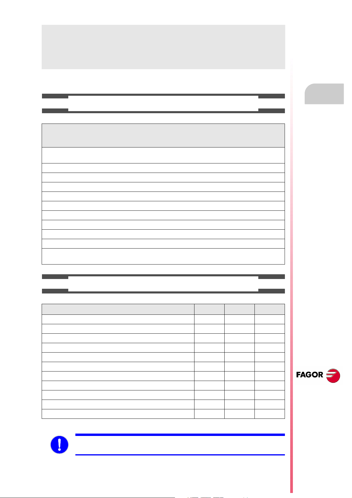
BASIC CHARACTERISTICS OF THE DIFFERENT MODELS.
8055 FL
8055i FL
8055i FL EN
Built-in 8055i FL
8055i FL EN
Enclosure 8055 FL 8055 Power
USB Standard Standard
Block processing time 3.5 ms 0.9 ms
RAM memory 1Mb 1 Mb
Software for 7 axes ----- Option
TCP transformation ----- Option
C axis (Lathe) ----- Option
Y axis (Lathe) ----- Option
Look-ahead 100 blocks 200 blocks
Flash Memory 512Mb / 2Gb Option
512Mb on the EN model
8055 Power
8055i Power
8055i Power
Option
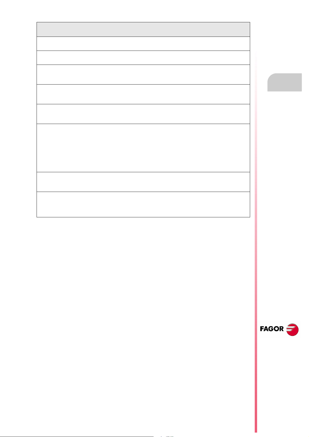
HARDWARE OPTIONS OF THE 8055I CNC
Analog Digital Engraving
Ethernet Option Option Option
RS-232 serial line Standard Standard Standard
16 digital inputs and 8 outputs (I1 to I16 and O1 to O8) Standard Standard Standard
Another 40 digital inputs and 24 outputs (I65 to I104 and O33 to O56) Option Option Option
Probe inputs Standard Standard Standard
Spindle (feedback input and analog output) Standard Standard Standard
Electronic handwheels Standard Standard Standard
4 axes (feedback and velocity command) Option Option - - -
Remote CAN modules, for digital I/O expansion (RIO). Option Option - - -
Sercos servo drive system for Fagor servo drive connection. - - - Option - - -
CAN servo drive system for Fagor servo drive connection. - - - Option - - -
Before start-up, verify that the machine that integrates this CNC meets the 89/392/CEE Directive.
CNC 8055
CNC 8055i
·7·
Page 8
About the product
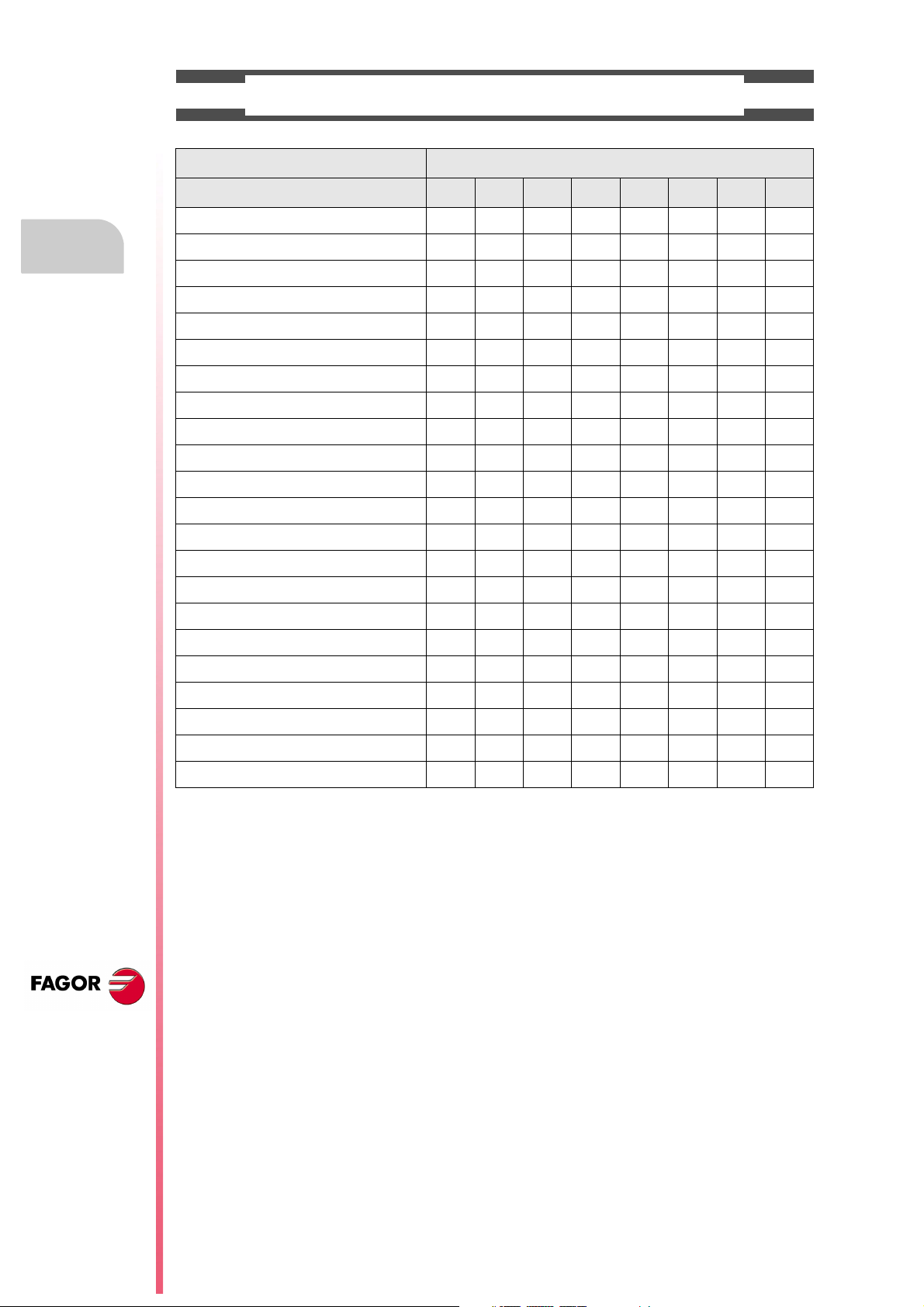
SOFTWARE OPTIONS OF THE 8055 AND 8055I CNCS.
Model
GP M MC MCO EN T TC TCO
Number of axes with standard software 4 4 4 4 3 2 2 2
Number of axes with optional software 7 7 7 7 ----- 4 or 7 4 or 7 4 or 7
Electronic threading ----- Stand. Stand. Stand. Stand. Stand. Stand. Stand.
Tool magazine management: ----- Stand. Stand. Stand. ----- Stand. Stand. Stand.
Machining canned cycles ----- Stand. Stand. ----- Stand. Stand. Stand. -----
Multiple machining ----- Stand. Stand. ----- Stand. ----- ----- -----
Solid graphics ----- Stand. Stand. Stand. ----- Stand. Stand. Stand.
Rigid tapping ----- Stand. Stand. Stand. Stand. Stand. Stand. Stand.
Tool live monitoring ----- Opt. Opt. Opt. Stand. Opt. Opt. Opt.
Probing canned cycles ----- Opt. Opt. Opt. Stand. Opt. Opt. Opt.
DNC Stand. Stand. Stand. Stand. Stand. Stand. Stand. Stand.
COCOM version Opt. Opt. Opt. Opt. ----- Opt. Opt. Opt.
Profile editor Stand. Stand. Stand. Stand. ----- Stand. Stand. Stand.
Tool radius compensation Stand. Stand. Stand. Stand. Stand. Stand. Stand. Stand.
CNC 8055
CNC 8055i
Tangential control Opt. Opt. Opt. Opt. ----- Opt. Opt. Opt.
Retracing ----- Opt. Opt. Opt. Stand. Opt. Opt. Opt.
Setup assistance Stand. Stand. Stand. Stand. Stand. Stand. Stand. Stand.
Irregular pockets with islands ----- Stand. Stand. Stand. ----- ----- ----- -----
TCP transformation ----- Opt. Opt. Opt. ----- ----- ----- -----
C axis (on Lathe) ----- ----- ----- ----- ----- Opt. Opt. Opt.
Y axis (on Lathe) ----- ----- ----- ----- ----- Opt. Opt. Opt.
Telediagnosis Opt. Opt. Opt. Opt. Stand. Opt. Opt. Opt.
·8·
Page 9

DECLARATION OF CONFORMITY
The manufacturer:
Fagor Automation S. Coop.
Barrio de San Andrés Nº 19, C.P. 20500, Mondragón -Guipúzcoa- (SPAIN).
Declares:
Under their responsibility that the product:
8055 / 8055i CNC
Consisting of the following modules and accessories:
MONITOR-8055, MONITOR-55-11-USB
OP-8055
KS 50/55, KB-40/55-ALFA, DVD AMPLI 8055
PSB-8055
CPU-KEY CF 8055 FL LARGE, CPU-KEY CF 8055 Power LARGE
AXES 8055 VPP
I/O 8055, COVER 8055, SERCOS 8055
Remote modules RIO
CNC 8055i FL, CNC 8055i Power
ANALOG 8055i-B, 40I/24O-8055i-B, ANALOG+40I/24O-B, COVER ANA+I/O-8055i-B
ETHERNET-CAN-SERCOS, ETHERNET-CAN-CAN AXES, ETHERNET-CAN AXES
Note.
Some additional characters may follow the references mentioned above. They all comply with the directives
listed. However, check that that's the case by checking the label of the unit itself.
Referred to by this declaration with following directives:
Low voltage regulations.
EN 60204-1: 2006 Electrical equipment on machines — Part 1. General requirements.
Regulation on electromagnetic compatibility.
EN 61131-2: 2007 PLC — Part 2. Requirements and equipment tests.
As instructed by the European Community Directives 2006/95/EEC on Low Voltage and
2004/108/EC on Electromagnetic Compatibility and its updates.
In Mondragón, July 27th, 2010.
CNC 8055
CNC 8055i
·9·
Page 10

Page 11
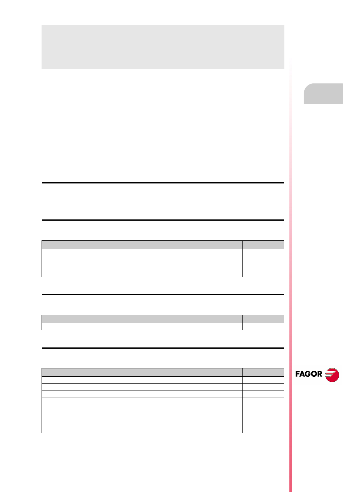
VERSION HISTORY
Here is a list of the features added in each software version and the manuals that describe them.
The version history uses the following abbreviations:
INST Installation manual
PRG Programming manual
OPT Operating manual
OPT-MC Operating manual for the MC option.
OPT-TC Operating manual for the TC option.
OPT-CO Manual of the CO manual
Software V01.00 October 2010
First version.
Software V01.20 April 2011
List of features Manual
Open communication. INST
Improvements to Look Ahead machining. INST
Blocks with helical interpolation in G51. PRG
G84. Tapping with relief. PRG
Software V01.08 August 2011
List of features Manual
S.m.p. OPLDECTI (P86). INST
Software V01.30 September 2011
List of features Manual
Gear ratio management on Sercos spindles INST
Improved feedrate limit management (FLIMIT). INST
New type of penetration in lathe type threading cycles. PRG
Improved lathe type thread repair. Partial repair. PRG
MC option: Rigid tapping with relief. OPT-MC
TC option: New type of penetration in threading cycles. OPT-TC
TC option: Improved thread repair. Partial and multi-entry (start) thread repair. OPT-TC
TC option: Zig-zag entry to the groove at the starting point of the groove. OPT-TC
CNC 8055
CNC 8055i
·11·
Page 12
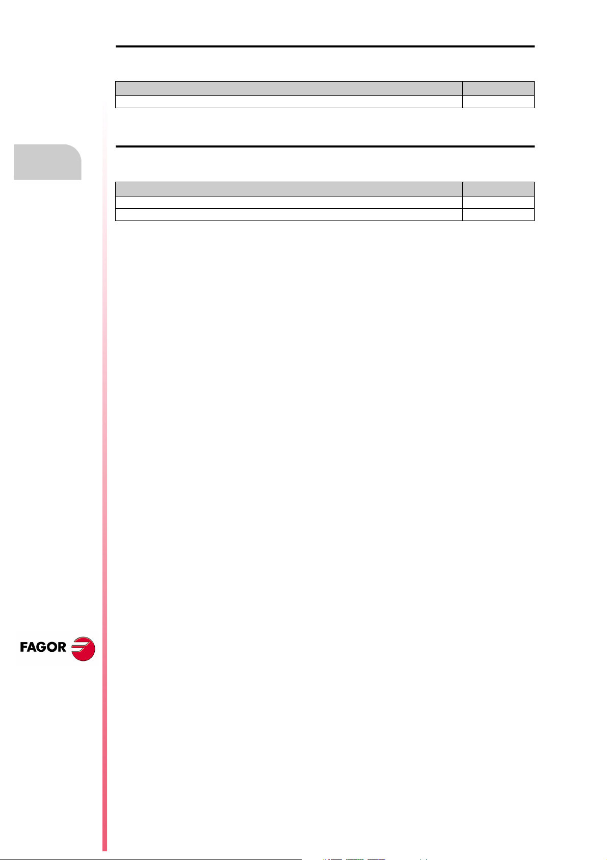
Version history
Software V01.31 October 2011
List of features Manual
CNC 8055 FL Engraving model INST / OPT/ PRG
Software V01.40 January 2012
List of features Manual
Execution of M3, M4 and M5 using PLC marks INST / PRG
Values 12 and 43 of variable OPMODE in conversational work mode. INST
CNC 8055
CNC 8055i
·12·
Page 13
SAFETY CONDITIONS
Read the following safety measures in order to prevent harming people or damage to this product and those
products connected to it.
This unit may only be repaired by authorized personnel at Fagor Automation.
Fagor Automation shall not be held responsible of any physical damage or defective unit resulting from not
complying with these basic safety regulations.
PRECAUTIONS AGAINST PERSONAL DAMAGE
• Interconnection of modules.
Use the connection cables provided with the unit.
• Use proper Mains AC power cables
To avoid risks, use only the Mains AC cables recommended for this unit.
• Avoid electrical overloads.
In order to avoid electrical discharges and fire hazards, do not apply electrical voltage outside the range
selected on the rear panel of the central unit.
• Ground connection.
In order to avoid electrical discharges, connect the ground terminals of all the modules to the main
ground terminal. Before connecting the inputs and outputs of this unit, make sure that all the grounding
connections are properly made.
• Before powering the unit up, make sure that it is connected to ground.
In order to avoid electrical discharges, make sure that all the grounding connections are properly made.
• Do not work in humid environments.
In order to avoid electrical discharges, always work under 90% of relative humidity (non-condensing)
and 45 ºC (113º F).
• Do not work in explosive environments.
In order to avoid risks or damages, do no work in explosive environments.
CNC 8055
CNC 8055i
·13·
Page 14
CNC 8055
CNC 8055i
• Working environment.
This unit is ready to be used in industrial environments complying with the directives and regulations
effective in the European Community.
Fagor Automation shall not be held responsible for any damage suffered or caused when installed in
other environments (residential or homes).
• Install this unit in the proper place.
It is recommended, whenever possible, to install the CNC away from coolants, chemical product, blows,
etc. that could damage it.
This unit complies with the European directives on electromagnetic compatibility. Nevertheless, it is
recommended to keep it away from sources of electromagnetic disturbance such as:
Powerful loads connected to the same AC power line as this equipment.
Safety conditions
Nearby portable transmitters (Radio-telephones, Ham radio transmitters).
Nearby radio/TV transmitters.
Nearby arc welding machines.
Nearby High Voltage power lines.
Etc.
•Enclosures.
The manufacturer is responsible of assuring that the enclosure involving the equipment meets all the
currently effective directives of the European Community.
• Avoid disturbances coming from the machine tool.
The machine-tool must have all the interference generating elements (relay coils, contactors, motors,
etc.) uncoupled.
DC relay coils. Diode type 1N4000.
AC relay coils. RC connected as close to the coils as possible with approximate values of R=220
AC motors. RC connected between phases, with values of R=300 / 6 W y C=0,47 µF / 600 V.
• Use the proper power supply.
Use an external regulated 24 Vdc power supply for the inputs and outputs.
• Grounding of the power supply.
The zero volt point of the external power supply must be connected to the main ground point of the
machine.
• Analog inputs and outputs connection.
It is recommended to connect them using shielded cables and connecting their shields (mesh) to the
corresponding pin.
• Ambient conditions.
The working temperature must be between +5 ºC and +40 ºC (41ºF and 104º F)
The storage temperature must be between -25 ºC and +70 ºC. (-13 ºF and 158 ºF)
• Monitor enclosure (CNC 8055) or central unit ( CNC 8055i)
Guarantee the required gaps between the monitor or the central unit and each wall of the enclosure.
Use a DC fan to improve enclosure ventilation.
• Power switch.
This power switch must be mounted in such a way that it is easily accessed and at a distance between
0.7 meters (27.5 inches) and 1.7 meters (5.5ft) off the floor.
PRECAUTIONS AGAINST PRODUCT DAMAGE
1 W y C=0,2 µF / 600 V.
·14·
Page 15
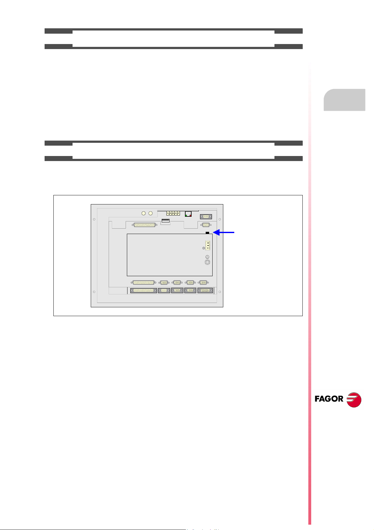
PROTECTIONS OF THE UNIT ITSELF (8055)
OUT
IN
X7
X1
X8
X9
X2
X10
X3
X11X4X12
X5
X13
X6
+24V
0V
FUSIBLE
FUSE
• "Axes" and "Inputs-Outputs" modules.
All the digital inputs and outputs have galvanic isolation via optocouplers between the CNC circuitry
and the outside.
They are protected by an external fast fuse (F) of 3.15 A 250V against overvoltage of the external power
supply (over 33 Vdc) and against reverse connection of the power supply.
• Monitor.
The type of protection fuse depends on the type of monitor. See identification label of the unit itself.
PROTECTIONS OF THE UNIT ITSELF (8055I)
• Central Unit.
It has a 4 A 250V external fast fuse (F).
• Inputs-Outputs.
All the digital inputs and outputs have galvanic isolation via optocouplers between the CNC circuitry
and the outside.
Safety conditions
CNC 8055
CNC 8055i
·15·
Page 16
PRECAUTIONS DURING REPAIR
i
Do not get into the inside of the unit. Only personnel authorized by Fagor Automation may manipulate
the inside of this unit.
Do not handle the connectors with the unit connected to main AC power. Before manipulating the
connectors (inputs/outputs, feedback, etc.) make sure that the unit is not connected to AC power.
SAFETY SYMBOLS
Safety conditions
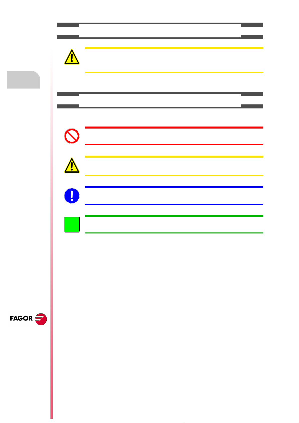
• Symbols which may appear on the manual.
Symbol for danger or prohibition.
It indicates actions or operations that may cause damage to people or to units.
Warning symbol.
It indicates situations that may be caused by certain operations and the actions to be taken to prevent
them.
Obligation symbol.
It indicates actions and operations that must be carried out.
Information symbol.
It indicates notes, warnings and advises.
CNC 8055
CNC 8055i
·16·
Page 17
WARRANTY TERMS
INITIAL WARRANTY
All products manufactured or marketed by FAGOR carry a 12-month warranty for the end user which could
be controlled by the our service network by means of the warranty control system established by FAGOR
for this purpose.
In order to prevent the possibility of having the time period from the time a product leaves our warehouse
until the end user actually receives it run against this 12-month warranty, FAGOR has set up a warranty
control system based on having the manufacturer or agent inform FAGOR of the destination, identification
and on-machine installation date, by filling out the document accompanying each FAGOR product in the
warranty envelope. This system, besides assuring a full year of warranty to the end user, enables our service
network to know about FAGOR equipment coming from other countries into their area of responsibility.
The warranty starting date will be the one appearing as the installation date on the above mentioned
document. FAGOR offers the manufacturer or agent 12 months to sell and install the product. This means
that the warranty starting date may be up to one year after the product has left our warehouse so long as
the warranty control sheet has been sent back to us. This translates into the extension of warranty period
to two years since the product left our warehouse. If this sheet has not been sent to us, the warranty period
ends 15 months from when the product left our warehouse.
This warranty covers all costs of material and labour involved in repairs at FAGOR carried out to correct
malfunctions in the equipment. FAGOR under takes to repair or replace their products within the period from
the moment manufacture begins until 8 years after the date on which it disappears from the catalog.
FAGOR has exclusive competence in deciding whether the repair enters within the term defined as the
warranty period.
EXCLUDING CLAUSES
Repairs will be carried out on our premises. Therefore, all expenses incurred as a result of trips made by
technical personnel to carry out equipment repairs, despite these being within the above-mentioned period
of warranty, are not covered by the warranty.
Said warranty will be applied whenever the equipment has been installed in accordance with instructions,
has not be mistreated, has not been damaged by accident or by negligence and has not been tampered
with by personnel not authorized by FAGOR. If, once servicing or repairs have been made, the cause of
the malfunction cannot be attributed to said elements, the customer is obliged to cover the expenses
incurred, in accordance with the tariffs in force.
Other warranties, implicit or explicit, are not covered and FAGOR AUTOMATION cannot be held responsible
for other damages which may occur.
CNC 8055
CNC 8055i
·17·
Page 18
WARRANTY ON REPAIRS
In a similar way to the initial warranty, FAGOR offers a warranty on standard repairs according to the
following conditions:
PERIOD
CONCEPT
EXCLUDING CLAUSES
When the customer does not choose the standard repair and just the faulty material has been replaced,
Warranty terms
the warranty will cover just the replaced parts or components within 12 months.
For sold parts the warranty is 12 moths length.
The SERVICE CONTRACT is available for the distributor or manufacturer who buys and installs our CNC
systems.
12 months.
Covers parts and labor for repairs (or replacements) at the network's own
facilities.
The same as those applied regarding the chapter on initial warranty.
If the repair is carried out within the warranty period, the warranty extension
has no effect.
MAINTENANCE CONTRACTS
CNC 8055
CNC 8055i
·18·
Page 19

MATERIAL RETURNING TERMS
When sending the central nit or the remote modules, pack them in its original package and packaging
material. If the original packaging material is not available, pack it as follows:
1. Get a cardboard box whose three inside dimensions are at least 15 cm (6 inches) larger than those
of the unit. The cardboard being used to make the box must have a resistance of 170 kg. (375 pounds).
2. Attach a label indicating the owner of the unit, person to contact, type of unit and serial number.
3. In case of failure, also indicate the symptom and a short description.
4. Wrap the unit in a polyethylene roll or similar material to protect it.
5. When sending the central unit, protect especially the screen.
6. Pad the unit inside the cardboard box with polyurethane foam on all sides.
7. Seal the cardboard box with packing tape or industrial staples.
CNC 8055
CNC 8055i
·19·
Page 20

Material returning terms
CNC 8055
CNC 8055i
·20·
Page 21
ADDITIONAL REMARKS
FAGOR
I/O
X1
X2
X3
AXES
X1 X2
X3 X4
X5 X6
X7 X8
X9
X10
CPU
X1 X2
CMPCT
FLASH
ETH
COM1
X3
C
D
E
F
0
B
A
9
8
1
7
2
6
3
5
4
IN
OUT
NODE
USB
(A)
(B)
X1
W1
Mount the CNC away from coolants, chemical products, blows, etc. which could damage it. Before turning
the unit on, verify that the ground connections have been properly made.
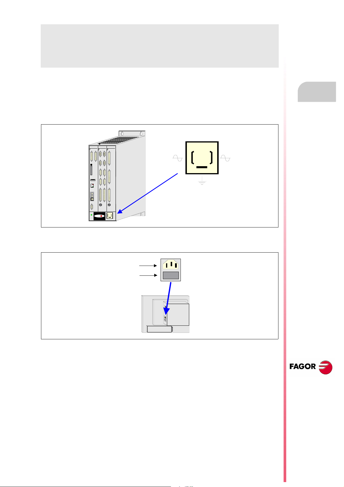
To prevent electrical shock at the central unit of the 8055 CNC, use the proper mains AC connector at the
power supply module. Use 3-wire power cables (one for ground connection).
To prevent electrical shock at the monitor of the 8055 CNC, use the proper mains AC connector (A) with
3-wire power cables (one of them for ground connection).
Before turning on the monitor of the 8055 CNC and verifying that the external AC line (B) fuse of each unit
is the right one. See identification label of the unit itself.
In case of a malfunction or failure, disconnect it and call the technical service. Do not get into the inside
of the unit.
CNC 8055
CNC 8055i
·21·
Page 22

Additional remarks
CNC 8055
CNC 8055i
·22·
Page 23

FAGOR DOCUMENTATION
OEM manual
It is directed to the machine builder or person in charge of installing and starting-up the CNC.
USER-M manual
Directed to the end user.
It describes how to operate and program in M mode.
USER-T manual
Directed to the end user.
It describes how to operate and program in T mode.
MC Manual
Directed to the end user.
It describes how to operate and program in MC mode.
It contains a self-teaching manual.
TC Manual
Directed to the end user.
It describes how to operate and program in TC mode.
It contains a self-teaching manual.
MCO/TCO model
Directed to the end user.
It describes how to operate and program in MCO and TCO mode.
Examples-M manual
Directed to the end user.
It contains programming examples for the M mode.
Examples-T manual
Directed to the end user.
It contains programming examples for the T mode.
WINDNC Manual
It is directed to people using the optional DNC communications software.
It is supplied in a floppy disk with the application.
WINDRAW55 Manual
Directed to people who use the WINDRAW55 to create screens.
It is supplied in a floppy disk with the application.
CNC 8055
CNC 8055i
·23·
Page 24

Fagor documentation
CNC 8055
CNC 8055i
·24·
Page 25

GENERAL CONCEPTS
1
This manual describes how to operate with the CNC with the monitor-keyboard and the operator
panel.
The Monitor-Keyboard unit consists of:
• The Monitor or CRT screen, which is used to show the required system information.
• The keyboard is used to communicate with the CNC; the operator may request information on
commands or change the CNC status using new instructions.
CNC 8055
CNC 8055i
·T· MODEL
SOFT: V01.4X
·25·
Page 26

1.
Part programs
GENERAL CONCEPTS
Operating manual
1.1 Part programs
Editing
To create a part-program, access the Edit mode.
The new part-program edited can be stored in the CNC's RAM memory, in the hard disk (KeyCF)
or in a remote disk. It is also possible to save a copy of the part-programs in a PC connected through
the serial line. See UTILITIES mode.
When using a PC through serial line, proceed as follows:
• Execute the WINDNC application program at the PC.
• Activate DNC communications at the CNC.
• Select the work directory.
Option: Utilities\ Directory\ Serial L.\ Change directory.
In the edit mode, it is possible to modify the part-programs located in the CNC's RAM memory, in
a hard disk (KeyCF) or in a remote disk.
Execution
Part-programs stored anywhere may be executed or simulated.
The user customizing programs must be in RAM memory so the CNC can execute them.
The GOTO and RPT instructions cannot be used in programs that are executed from a PC connected
through the serial line.
Only subroutines stored in the CNC's RAM memory can be executed. Therefore, to execute a
subroutine stored in a PC or in the hard disk, it must be copied into the CNC's RAM memory.
From a program in execution, it is possible to execute another program located in RAM memory,
in a PC or in the hard disk using the EXEC instruction.
Utilities
The utilities mode, lets display the part-program directory of all the devices, make copies, delete,
rename and even set the protections for any of them.
Ethernet
When having the Ethernet option and the CNC has been configured as a node within the computer
network, the following is possible from any PC of the network:
• Access the part-program directory of the hard disk (KeyCF).
• Edit, modify, delete, rename, etc., the programs stored on the hard disk (KeyCF).
• Copy programs from the hard disk to the PC and vice versa.
CNC 8055
CNC 8055i
·T· MODEL
SOFT: V01.4X
·26·
Operations that may be carried out with part-programs:
Page 27
Operating manual
See the program directory of ...
See the subroutine directory of ...
Create the work directory from ...
Change the work directory from ...
Edit a program from ...
Modify a program from ...
Delete a program from ...
Copy from/to RAM memory to/from ...
Copy from/to hard disk to/from ...
Copy from/to DNC to/from ...
Rename a program from ...
Change the comment of a program from ...
Change the protections of a program from ...
Execute a part-program from ...
Execute a user program from ...
Execute a PLC program from ...
Execute programs with GOTO or RPT instructions from ...
Execute subroutines residing in ...
Execute programs with the EXEC instruction, in RAM from ...
Execute programs with the EXEC instruction, in hard disk from ...
Execute programs with the EXEC instruction, in DNC from ...
Open programs with the OPEN instruction, in RAM from ...
Open programs with the OPEN instruction, in hard disk from ...
Open programs with the OPEN instruction, in DNC from ...
Via Ethernet:
See from a PC the program directory of ...
See from a PC the subroutine directory of ...
See from a PC, a directory in ...
RAM Hard
disk
Ye s
Ye s
No
No
Ye s
Ye s
Ye s
Ye s
Ye s
Ye s
Ye s
Ye s
Ye s
Ye s
Ye s
Ye s
Ye s
Ye s
Ye s
Ye s
Ye s
Ye s
Ye s
Ye s
No
No
No
Ye s
No
No
No
Ye s
Ye s
Ye s
Ye s
Ye s
Ye s
Ye s
Ye s
Ye s
Ye s
Ye s
No
Ye s
No
Ye s
Ye s
Ye s
Ye s
Ye s
Ye s
Ye s
No
No
DNC
Ye s
No
No
Ye s
No
No
Ye s
Ye s
Ye s
Ye s
No
No
No
Ye s
No
No
No
No
Ye s
Ye s
No
Ye s
Ye s
No
No
No
No
1.
Part programs
GENERAL CONCEPTS
CNC 8055
CNC 8055i
·T· MODEL
SOFT: V01.4X
·27·
Page 28
1.
GENERAL CONCEPTS
Monitor information layout
Operating manual
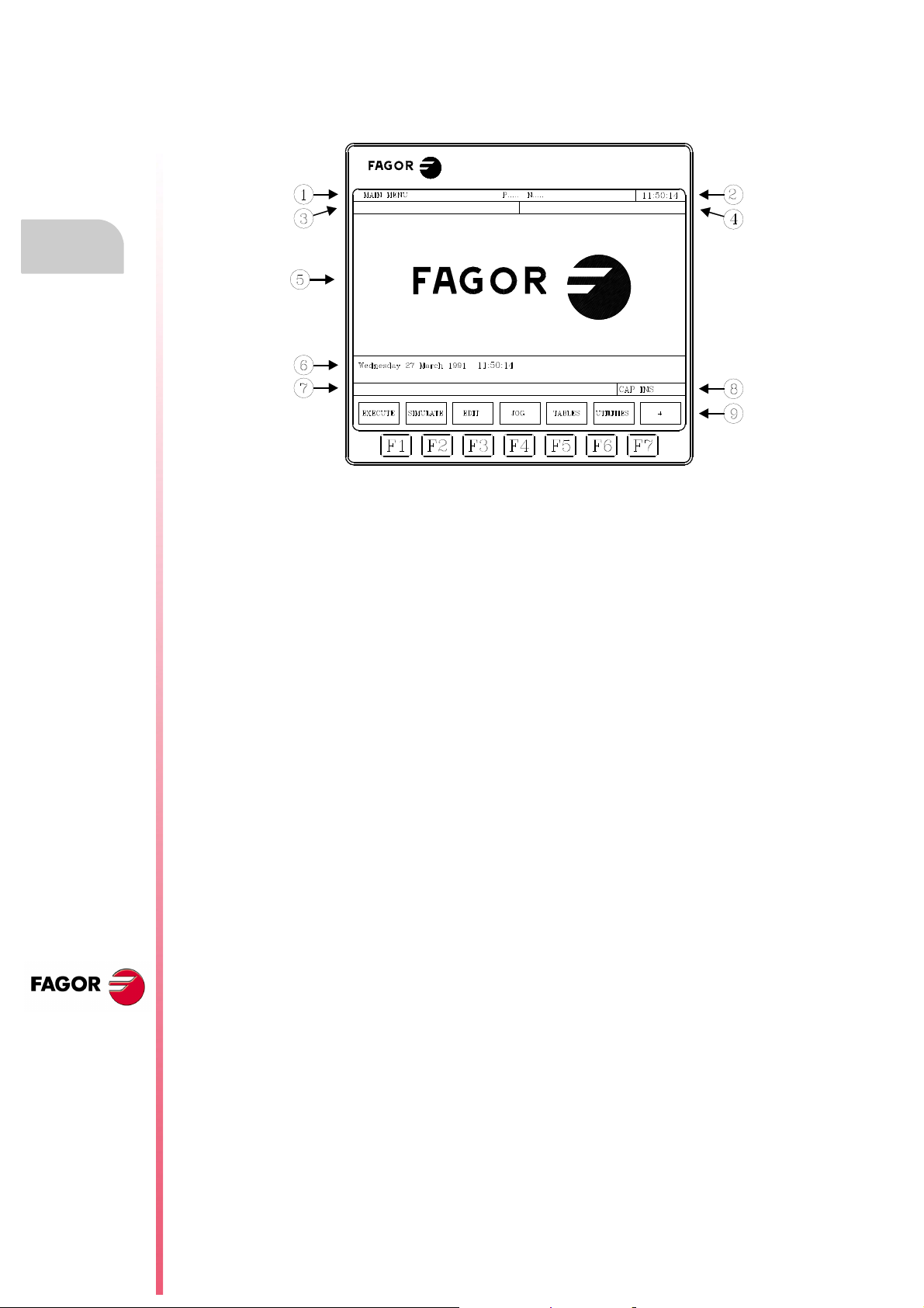
1.2 Monitor information layout
The monitor is divided into the following areas or display windows:
CNC 8055
CNC 8055i
1. This window indicates the selected operating mode, as well as the program number and the
number of the active block. The program status is also indicated (in execution or interrupted)
and if the DNC is active.
2. This window indicates the time in the " hours : minutes : seconds".
3. This window displays the messages sent to the operator from the part program or via DNC.
The last message received will be shown regardless of where it has come from.
4. This window will display messages from the PLC.
If the PLC activates two or more messages, the CNC will always display the one with the highest
priority, which is the message with the smallest number. In this way, MSG1 will have the highest
priority and MSG255 will have the lowest.
In this case the CNC will display the character + (plus sign), indicating that there are more
messages activated by the PLC, it being possible to display them if the ACTIVE MESSAGE
option is accessed in the PLC mode.
In this window the CNC will also display the character * (asterisk), to indicate that at least one
of the 256 user-defined screens is active.
The screens which are active will be displayed, one by one, if the ACTIVE PAGES option is
accessed in the PLC mode.
5. Main window.
Depending on the operating mode, the CNC will show in this window all the information
necessary.
When a CNC or PLC error is produced the system displays this in a superimposed horizontal
window.
The CNC will always display the most important error. The CNC will show the [] key to indicate
that another less important error has also occurred and to press this key to view its message.
The CNC will show the [] key to indicate that another more important error has also occurred
and to press this key to view its message.
6. Editing window.
In some operating modes the last four lines of the main window are used as editing area.
7. CNC reports window. (errors detected in edition, nonexistent program, etc.).
·T· MODEL
SOFT: V01.4X
·28·
Page 29

Operating manual
8. This window shows the following information:
SHF Indicates that the [SHIFT] key has been pressed to activate the second function
CAP This indicates capital letters ([CAPS] key). The CNC will understand that capital
INS/REP Indicates if it is insert mode (INS) or substitution (REP) mode. It is selected by
MM/INCH Indicates the unit system (millimeters or inches) selected for display.
9. Shows the different options which can be selected with soft-keys F1 thru F7.
of the keys.
For example, if the [9] key is pressed after the [SHIFT] key, the CNC will
understand that the "$" character is required.
letters are required whenever this is active.
means of the [INS] key.
1.
GENERAL CONCEPTS
Monitor information layout
CNC 8055
CNC 8055i
·T· MODEL
SOFT: V01.4X
·29·
Page 30
Operating manual
1.3 Keyboard layout
Depending on the utility of the different keys, the CNC keyboard may be considered to be laid out
as follows:
Alphanumeric keyboard for the data entry in memory, selection of axes, tool offset, etc.
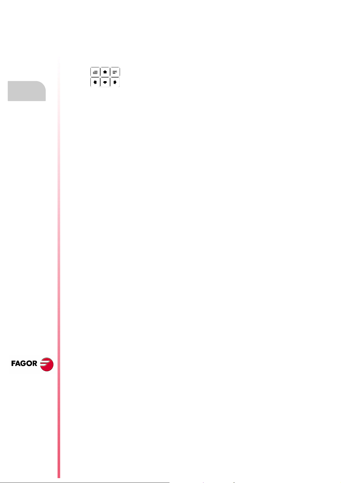
Keys which allow the information shown on screen to be moved forward or
backward, page to page or line to line, as well as moving the cursor all over the
screen.
1.
Keyboard layout
GENERAL CONCEPTS
[CL][CLEAR] To delete the character over which the cursor is positioned or the last one entered
if the cursor is at the end of the line.
[INS] To select the insert or overwrite mode.
[ENTER] To validate the CNC and PLC commands generated in the editing window.
[HELP] To access to the help system in any operating mode.
[RESET] To initialize the history of the program in execution, by assigning it the values
defined by machine parameters. It is necessary for the program to be stopped for
the CNC to accept this key.
[ESC] To go back to the previous operating option shown on the monitor.
[MAIN MENU]To access the CNC's main menu directly.
[RECALL] In conversational modes, it assigns the value of a coordinate to the selected field.
[PPROG] In the conversational modes, it accesses the list of part-programs stored.
[F1] to [F7] Softkeys or functions keys for selecting the different operating options shown on
the monitor.
Specific keys to select canned cycles in the MC and TC work modes.
There are also the following special keystroke sequences:
[SHIFT]+[RESET]
The result of this keystroke sequence is the same as turning the CNC off and back on. This option
must be used after modifying the CNC's machine parameters so they're assumed by the CNC.
[SHIFT]+[CL]
This keystroke sequence clears (blanks out) the CRT screen. Press any key to restore its normal
state.
If an error occurs or a PLC/CNC message is received while the screen is blank, the screen
restores its normal state.
CNC 8055
CNC 8055i
·T· MODEL
SOFT: V01.4X
[SHIFT]+[next page]
To display on the right hand side of the screen the position of the axes and the status of the
program in progress.
It may be used in any operating mode.
Press the same keystroke sequence to restore the previous display.
·30·
Page 31

Operating manual
1.3.1 The EDIT, SIMUL and EXEC keys
The keyboards of the M and T models have these new keys:
"EDIT" To access the editing mode.
"SIMUL" To access the simulation mode.
"EXEC" To access the execution mode.
In the MC, TC and MCO/TCO modes, these direct accesses are available when working in M or
T mode (non-conversational). To access them, use the "P.PROG" key instead of "EDIT" and the
"GRAPHICS" key instead of "SIMUL".
Direct access to the editing mode, "EDIT" key.
When pressing this key in the editing and simulation modes, one edits the last program simulated
or executed. If the corresponding program is being executed or simulated, one will edit the one that
was last edited.
1.
When pressing this key in any other work mode, it starts editing the last program edited.
If there is no previous program, it requests the name of a new program.
To restrict the editing to the last program edited, simulated or executed, assign to the NEXEDI
variable one of the following values:
NEXEDI=0 Not restricted, it opens the last one edited, simulated or executed.
NEXEDI=1 Always the last program edited.
NEXEDI=2 Always the last program simulated.
NEXEDI=3 Always the last program executed.
If the corresponding program is being executed or simulated, it issues a warning. If there is no
previous program, it requests the name of a new program.
Direct access to the simulation mode, "SIMUL" key.
Pressing this key starts the simulation of the last program edited, simulated or executed. If there
is no previous program, it requests the name of a new program.
If the simulation or execution mode is active, only the active mode will be shown, no program is
selected.
To restrict the simulation to the last program edited, simulated or executed, assign to the NEXSIM
variable one of the following values:
NEXSIM=0 Not restricted, it opens the last one edited, simulated or executed.
NEXSIM=1 Always the last program edited.
NEXSIM=2 Always the last program simulated.
NEXSIM=3 Always the last program executed.
Keyboard layout
GENERAL CONCEPTS
If the corresponding program is being executed or simulated, it issues a warning. If there is no
previous program, it requests the name of a new program.
CNC 8055
CNC 8055i
·T· MODEL
SOFT: V01.4X
·31·
Page 32

1.
Operating manual
Direct access to the execution mode, "EXEC" key.
Pressing this key starts the execution of the last program edited, simulated or executed. If there is
no previous program, it requests the name of a new program.
If the simulation or execution mode is active, only the active mode will be shown, no program is
selected.
To restrict the execution to the last program edited, simulated or executed, assign to the NEXEXE
variable one of the following values:
NEXEXE=0 Not restricted, it opens the last one edited, simulated or executed.
NEXEXE=1 Always the last program edited.
NEXEXE=2 Always the last program simulated.
NEXEXE=3 Always the last program executed.
If the corresponding program is being executed or simulated, it issues a warning. If there is no
previous program, it requests the name of a new program.
Keyboard layout
GENERAL CONCEPTS
CNC 8055
CNC 8055i
·T· MODEL
SOFT: V01.4X
·32·
Page 33

Operating manual
1.4 Layout of the operator panel
Depending on the utility of the different parts, the CNC operator panel may be considered to be laid
out as follows.
1. Position of the emergency button or electronic handwheel.
2. Keyboard for manual movement of axes.
3. Selector switch with the following functions:
Select the multiplication factor of the number of pulses from the electronic handwheel (1, 10 or
100).
Select the incremental value of the movement of the axes in movements made in the "JOG"
mode.
Modify the programmed axis feedrate between 0% and 120%
4. Keyboard which allows the spindle to be controlled, it being possible to activate it in the desired
direction, stop it or vary the programmed turning speed between percentage values established
by means of spindle machine parameters "MINSOVR" and "MAXOVR", with an incremental step
established by means of the spindle machine parameter "SOVRSTEP".
5. Keyboard for CYCLE START and CYCLE STOP of the block or program to be executed.
1.
GENERAL CONCEPTS
Layout of the operator panel
CNC 8055
CNC 8055i
·T· MODEL
SOFT: V01.4X
·33·
Page 34

1.
Operating manual
GENERAL CONCEPTS
Layout of the operator panel
CNC 8055
CNC 8055i
·T· MODEL
SOFT: V01.4X
·34·
Page 35

OPERATING MODES
2
After turning on the CNC, or after pressing the sequence of [SHIFT]+[RESET] keys, the FAGOR
logo will appear in the main window of the monitor or the screen previously prepared as page 0 by
means of the screen customizing (graphic editor) tools.
If the CNC shows the message " Initialize? (ENTER / ESC) ", it should be borne in mind that after
pressing the [ENTER] key, all the information stored in memory and the machine parameters are
initialized to default values indicated in the installation manual.
On the lower part of the screen the main CNC menu will be shown, it being possible to select the
different operating modes by means of the softkeys F1 thru F7. Whenever the CNC menu has more
options than number of softkeys (7), the character "+" will appear in softkey F7. If this softkey is
pressed the CNC will show the rest of the options available.
Main menu options
The options which the main CNC menu will show after turning it on, after pressing the key sequence
[SHIFT]+[RESET] or after pressing the [MAIN MENU] softkey are:
EXECUTE Allows the execution of part programs in automatic or single block.
SIMULATE Allows simulation of parts programs in several modes.
EDIT Allows editing new and already-existing part programs.
JOG Allows manual control of the machine by means of the operator panel keys.
TABLES Allows CNC tables relating to part programs (zero offsets, tool offsets,
tools, tool magazine as well as global or local arithmetic parameters) to
be manipulated.
UTILITIES Allows program manipulation (copy, delete, rename, etc.)
STATUS It shows the CNC status and that of the DNC communication lines. It also
lets activate and deactivate the communication with a PC through DNC.
PLC Allows operation with the PLC (edit the program, monitor, change the
status of its variables, access to the active messages, errors, pages, etc).
SCREEN EDITOR
Allows, by means of a simple graphics editor, the creation of user-defined
screens (pages), which can later be activated from the PLC, used in
customized programs or presented when the unit is powered on (page 0).
MACHINE PARAMETERS
Allows the machine parameters to be set to adapt the CNC to the machine.
DIAGNOSIS Runs a test of the CNC.
While the CNC is executing or simulating a part program it allows any other type of operating mode
to be accessed without stopping the execution of the program. In this way it is possible to edit a
program while another is being executed or simulated.
It is not possible to edit the program which is being executed or simulated, nor execute or simulate
two part programs at the same time.
CNC 8055
CNC 8055i
·T· MODEL
SOFT: V01.4X
·35·
Page 36

Operating manual
(a) (b)
2.1 Help systems
The CNC allows access to the help system (main menu, operating mode, editing of commands, etc.)
at any time. To do this, you must press the [HELP] key and the CNC will show the corresponding
help page in the main window of the screen.
If the help consists of more than one page of information, the symbol(a) indicating
that this key can be pressed to access the following page or the symbol(b) indicating
that it is possible to press this key to access the previous page.
2.
The following assistance is available:
Operating assistance
Help systems
OPERATING MODES
This is accessed from the operating mode menu, or when one of these has been selected but none
of the options shown have been selected. In all these cases, the softkeys have a blue background
color.
It offers information on the operating mode or corresponding option.
While this information is available on screen it is not possible to continue operating the CNC via the
softkeys, it being necessary to press the [HELP] key again to recover the information which was
on the main screen before requesting help and continuing with the operation of the CNC.
The help system can also be abandoned by pressing the [ESC] key or the [MAIN MENU] key.
Editing assistance
This is accessed once one of the editing options has been selected (part programs, PLC program,
tables, machine parameters, etc.). In all these cases, the softkeys have a white background color.
It offers information on the corresponding option. While this information is available, it is possible
to continue operating with the CNC.
CNC 8055
CNC 8055i
·T· MODEL
SOFT: V01.4X
If the [HELP] key is pressed again, the CNC analyzes if the present editing status corresponds to
the same help page or not.
If another page corresponds to it, it displays this instead of the previous one and if the same one
corresponds, it recovers the information which was in the main window before requesting help.
The help menu can also be abandoned after pressing the [ESC] key, to return to the previous
operating option, or the [MAIN MENU] key to return to the main menu.
·36·
Page 37

Operating manual
Canned cycle editing assistance
It is possible to access this help when editing a canned cycle.
It offers information on the corresponding canned cycle and an editing assistance for the selected
canned cycle is obtained at this point.
For the user's own cycles a similar editing assistance can be obtained by means of a user program.
This program must be prepared with screen customizing instructions.
Once all the fields or parameters of the canned cycle have been defined the CNC will show the
information existing in the main window before requesting help.
The canned cycle which is programmed by means of editing assistance will be shown in the editing
window, and the operator can modify or complete this block before entering it in memory by pressing
the [ENTER] key.
2.
Editing assistance can be abandoned at any time by pressing the [HELP] key. The CNC will show
the information which existed on the main window before requesting help and allows programming
of the canned cycle to continue in the editing window.
The help menu can also be abandoned after pressing the [ESC] key, to return to the previous
operating option, or the [MAIN MENU] key to return to the main menu.
Help systems
OPERATING MODES
CNC 8055
CNC 8055i
·T· MODEL
SOFT: V01.4X
·37·
Page 38

2.
USB DISK
i
Operating manual
2.2 Software update
The software is loaded from the Diagnosis mode using the option <Configuration / Software
configuration / Load version>
It displays the following window:
Software update
OPERATING MODES
CNC 8055
CNC 8055i
The left panel shows the system devices available and their relevant subdirectories.
The right panel is divided in two halves:
• The top shows all the files contained in the software versions (".f55" extension).
• The bottom shows the data identifying the version selected in the top half.
Loading the version
To install a version, the user must follow the following procedure:
1. Select, in the left panel, the unit containing the new version to be installed.
To install a new version located in a "remote hard disk" or "USB disk", first transfer the ".f55" file to
the "vers" folder of the hard disk (KeyCF) and then load the version as mentioned next.
2. Place the cursor in the right panel, on the ".f55" file and press the softkey <INSTALL>. After
carrying out this task, it shows a dialog box requesting confirmation to resume the process:
F5 [OK] resume the process
[ESC] abort the process
3. Once the resuming of the operation has been confirmed, the CNC verifies that the file to be
installed is correct. During this operation, it displays a process bar with the message "checking..."
4. Then, it loads the code contained in the ".f55" file into the system flash memory. During this
operation, it displays a process bar with the message "loading..."
5. Finally, it verifies the checksum of the new version installed. This operation is identified with the
message "wait...".
If there is a CNC power outage during any of these processes, when powered back up, it goes on
loading the version from the interruption point.
If the interruption takes place while saving into the flash memory, it first checks the version file.
·T· MODEL
SOFT: V01.4X
·38·
Page 39

Operating manual
2.3 KeyCF (KeyCompactFlash)
The KeyCF will store the CNC configuration, i.e. the validation code, the software options, user
screens, PLC program backups and machine parameters. It also has memory for user programs.
Also, the CNC supports the management of several disks at the same time as well as the hard disk
(KeyCF):
• USB disk. The CNC selects a folder of a USB device and it considers it like its own hard disk.
From the user's point of view, the CNC has another hard disk.
• Remote hard disk. The CNC selects a directory of a PC shared in the network and it considers
it like its own hard disk. From the user's point of view, the CNC has a remote hard disk. It will
only store user programs.
2.
OPERATING MODES
KeyCF (KeyCompactFlash)
CNC 8055
CNC 8055i
·T· MODEL
SOFT: V01.4X
·39·
Page 40

2.
2.3.1 Directory structure
The purpose of these directories of the hard disk (hard disk, USB disk or remote disk) is to provide
the user with a space to save part-programs, tables, graphic files, etc. in an orderly fashion.
Directory /Prg
By default, this directory of the hard disk will store the user programs.
The OPEN and EXEC instructions can only be used in the subdirectory /Prg of the default hard disk
"by default", i.e. of the hard disk, USB disk or remote hard disk.
Directory /Tab
This directory of the hard disk will store the machine parameters and tables with the same format
OPERATING MODES
KeyCF (KeyCompactFlash)
and the same name currently stored in the WinDNC.
The files for the parameters of an axis and for leadscrew compensation are stored in the hard disk
by the axis name.
Within the parameter table for an axis, it will offer the option to <load/hard disk>. This option first
checks if the file <APn> is stored:
Operating manual
• Axis parameters: APX, APY, ..., APC.
• Leadscrew parameters: ALX, ALY, ..., ALC.
If it's missing, it checks if the file <MXn> is stored.
• Axis parameters: MX1, MX2, ...
• Leadscrew parameters: US1, US2, ...
The same procedure will be applied with the <load/DNC> option.
Directory /Pan
This directory of the hard disk stores the graphic files with extensions <*.pan>, <*.sim> and <*.wgd>.
Directory /Vers
The user can store the different software versions in this directory of the hard disk.
CNC 8055
CNC 8055i
·T· MODEL
SOFT: V01.4X
·40·
Page 41

Operating manual
Accessing the system from other devices
Through the WinDNC
From WinDNC it is possible to access the files of user programs, tables and screens located in the
hard disk as well as those located in the USB disk.
The WinDNC can only display the following devices:
• Memory.
• Default hard disk .
The "default hard disk" will be the first hard disk recognized by the CNC. The order of priorities is:
1.Hard disk (KeyCF).
2.USB disk.
3.Remote hard disk.
At the "default hard disk", only the default directory/Prg can be accessed. The rest of the
subdirectories are not accessible.
2.
Accessing the root directory of the DNC requires a WinDNC version 4.1 or higher. Likewise, sending
tables from/to the hard disk requires a WinDNC version 4.1.
Via FTP
It is possible to access (read and write) tables, machine parameters, graphic files and programs from
the network via FTP. All the disks will be available when accessing a CNC via FTP:
• Hard disk (KeyCF).
• USB disk.
• Remote hard disk.
OPERATING MODES
KeyCF (KeyCompactFlash)
CNC 8055
CNC 8055i
·T· MODEL
SOFT: V01.4X
·41·
Page 42

2.
Operating manual
OPERATING MODES
KeyCF (KeyCompactFlash)
CNC 8055
CNC 8055i
·T· MODEL
SOFT: V01.4X
·42·
Page 43

OPERATIONS VIA ETHERNET
i
3
The Ethernet option permits configuring the CNC as another node within the local area network.
This option makes it possible to communicate with other PC's to transfer files or carrying out
telediagnostic tasks.
To configure the CNC within a computer network, refer to the chapter on machine parameters for
Ethernet in the installation manual.
Once the connection to Ethernet has been configured, the following types of connections are
possible:
• Connection to a remote hard disk.
• Connection to a PC through WinDNC.
• Connection from a PC through an FTP client.
To communicate with the CNC, the PC must be configured just like another node within the local
area network or Internet and it must have the WinDNC (V4.0 or later) installed. The communication
through Ethernet does not require the DNC option.
CNC 8055
CNC 8055i
·T· MODEL
SOFT: V01.4X
·43·
Page 44

3.
i
Remote hard disk
OPERATIONS VIA ETHERNET
Operating manual
3.1 Remote hard disk
The CNC can have a local hard disk (at the CNC itself) or a remote hard disk accessible through
Ethernet.
The remote hard disk is configured by machine parameters. Refer to the chapter on machine
parameters for Ethernet in the installation manual.
As remote hard disk, it is possible to use the hard disk of a PC or just a folder. This memory space
may be shared by several CNC's or each may have its own memory space. The PC that makes its
hard disk (server) public must be connected to the local network.
The interface and the softkeys of the CNC will the same as if it were a local hard disk. When accessing
the CNC through WinDNC or FTP, the remote hard disk behaves like a local hard disk.
Protocol used
The NFS protocol is used to communicate with the remote hard disk. This protocol must be available
at the PC that is used as server.
CNC 8055
CNC 8055i
·T· MODEL
SOFT: V01.4X
·44·
Page 45

Operating manual
i
3.2 Connection to a PC through WinDNC
The PC operative system must be Windows® and it must have the WinDNC software installed (V4.0
or newer). The CNC must be configured just like another node within the local network or internet.
The access to a DNC server is configured by machine parameters. Refer to the chapter on machine
parameters for Ethernet in the installation manual.
Possible connections:
•From a PC.
The connection may be initiated at any PC and addressed to any CNC. Two PC's cannot be
connected to each other.
To establish the connection, the WinDNC allows the user to enter the CNC's IP address to be
used for the connection.
• From a CNC.
The connection is always addressed to the DNC server. The DNC server is defined by machine
parameters.
Communication status
As with the communication via serial line, the DNC status screen shows its status through Ethernet.
When having the DNC available, the top of the screen shows the message" DNC E". The connection
may be activated and deactivated from the softkey menu.
It is possible to connect several WinDNC (up to 10) simultaneously to the same CNC. The access
protection is by operation. If several WinDNC initiate an operation, the commands are processed
one by one while the rest of the WinDNC's wait.
3.
OPERATIONS VIA ETHERNET
Connection to a PC through WinDNC
CNC 8055
CNC 8055i
·T· MODEL
SOFT: V01.4X
·45·
Page 46

Operating manual
i
DISK BIN
PRG
ROOT
3.3 Access the CNC's hard disk from a PC
If the CNC is configured like another node in the network, it may be accessed from any PC of the
network knowing its IP. Only the CNC's hard disk may be accessed; i.e. it is not possible to access
programs in RAM nor read variables, tables, etc.
From the PC, it is possible to access the part-program directory of the hard disk and edit, modify,
etc. the programs stored. It is also possible to copy programs from the hard disk to the PC and vice
versa.
3.
Protocol used
The FTP protocol is used to access the hard disk of the CNC. The FTP protocol permits transferring
files between a PC and a CNC connected to a local network or to internet. The FTP client, in charge
of managing the transfer, must be installed at the PC. The interface depends on the FTP client being
used.
The PC operative system may be Windows, Linux or Unix.
Windows® includes an FTP client in its Internet Explorer application from version 5.x on. From
Windows® 98 on, the Windows explorer has its own integrated FTP client.
When accessing the CNC from a PC via FTP, it shows the following directory structure.
OPERATIONS VIA ETHERNET
Access the CNC's hard disk from a PC
BIN System folder used by the FTP protocol. It cannot be modified.
DISK CNC hard disk. The user can fully access it from the PC. Although subdirectories and files
may be defined, they won't be accessible from the CNC.
PRG Part-programs and PLC programs stored at the CNC. If this folder does not exist on start-up,
an empty one is created.
CNC 8055
CNC 8055i
·T· MODEL
SOFT: V01.4X
Although the user may create new directories through the FTP, only the programs contained in the
"PRG" directory may be seen from the CNC.
If the CNC does not have a hard disk, it will show the directory empty and it will not allow sending
any program.
File transfer
To copy a file from the PC to the CNC.
®
• In any Windows
the keyboard shortcuts [CTRL]+[C] and [CTRL]+[V].
To copy a file from the CNC to the PC.
• In Windows
and select the destination folder.
•In Windows
[CTRL]+[C] (copy) and [CTRL]+[V] (paste).
(95, 98, 2000 or XP) system. Drag the file from one folder to another or use
®
95 or 98. Click the right mouse button on the file, select the option to "Copy to folder"
®
2000 or XP. Drag the file from one folder to another or use the keyboard shortcuts
·46·
Page 47

Operating manual
i
Connection using Windows®95 or 98
Connection with a shared CNC without password
At the Web browser (e.g. IExplorer) or from the file explorer (only on Windows 98), write in the
command line the CNC's IP address.
For example: ftp://10.0.7.224
Connection with a shared CNC with password
At the Web browser (e.g. IExplorer) or from the file explorer (only on Windows 98), write in the
command line the user name, the password and the CNC's IP address. The user name is always
"cnc".
For example: ftp://cnc:password@10.0.17.62
Assign a name to the IP address
The IP address may be assigned a name for easier identification. This operation is carried out at
the PC and there are two different ways to do it.
• Editing the file "c:\windows\hosts". This file may be modified with any text editor.
In the file, add a line containing the CNC'S IP address and the name to identify it with. For
example:
10.0.7.40 CNC_1
10.1.6.25 MILL_MACH_01
3.
OPERATIONS VIA ETHERNET
Access the CNC's hard disk from a PC
On the Web browser or from the file explorer (only on Windows 98), write the defined name in
the command line.
For example (CNC without password): ftp://CNC_01.
For example (CNC with password): ftp://cnc:password@MILL_MACH_01
• Through the "Favorites" menu of the Web browser.
In the Web explorer, write the IP address in the command line. After accessing the site, select
the "Favorites" option on the menu add to favorites and assign a name to that IP address. This
way, it is possible to access the CNC by selecting the assigned name on the "Favorites" menu.
On the Iexplorer browser, it is called "Favorites". This name may vary depending on the Web browser
being used.
Connection using Windows®2000 or XP
The easiest way to access the CNC's hard disk from a PC is configuring a new connection. At the
file explorer, select My Network sites > Add network sites. It will show the Windows help to add
network sites that permits configuring the connection step by step. Press the –OK– button to go on
to the next step.
Follow the instructions shown on the screen to configure the connection; refer to the Windows® help
for additional information.
Connection with a shared CNC without password
1. First, select the network site, in this case an ftp folder. Write "ftp://" followed by the CNC's
IP address defined by machine parameter DIRIP (P24).
For example: ftp://10.0.17.62
2. Define how the session is initiated, anonymously or not When the CNC is shared without
password, the session is initiated anonymously.
3. Define the name to be associated with the new connection. This is the name that will appear
on the PC's net directory. Just select it from the list to start the connection.
For example: FAGOR_CNC
CNC 8055
CNC 8055i
·T· MODEL
SOFT: V01.4X
·47·
Page 48

3.
Operating manual
Connection with a shared CNC with password
1. First, select the network site, in this case an ftp folder. Write "ftp://" followed by the CNC's
IP address defined by machine parameter DIRIP (P24).
For example: ftp://10.0.17.62
2. Define the user name and how the session is initiated, anonymously or not. When the CNC is
shared with password, the session is not initiated anonymously. The user must identify itself and
it must be as "cnc" or "CNC".
3. Define the name to be associated with the new connection. This is the name that will appear
on the PC's net directory. Just select it from the list to start the connection.
For example: FAGOR_CNC
After the configuration is done and every time the connection is made, a window will open requesting
the user name and password. As user name, select "cnc" or "CNC" and as password the one defined
by machine parameter CNHDPAS1 (P7).
To make it easier, the –Save password– option may be selected in this window. This way, it will no
longer request the password when connecting again and it will access the hard disk directly.
Use the "save password" option with caution. Bear in mind that if you save the password, it will not
be requested for the connection and, therefore, anybody is free to access the CNC from the PC.
OPERATIONS VIA ETHERNET
Access the CNC's hard disk from a PC
CNC 8055
CNC 8055i
·T· MODEL
SOFT: V01.4X
·48·
Page 49

EXECUTE / SIMULATE
i
4
The EXECUTE operating mode allows the execution of part programs in automatic mode or in single
block mode.
The SIMULATE operating mode allows the simulation of part-programs in automatic or single block
mode. When wished to SIMULATE a part-program, the CNC will request the type of simulation to
be carried out.
When selecting one of these operating modes, one must indicate the location of the part-program
to be executed or simulated. The part program may be stored in the CNC's internal RAM memory,
in PC connected through the serial line or in the hard disk (KeyCF).
After pressing one of these softkeys, the CNC displays the corresponding part-program directory.
The program may be selected by:
• Keying in its number and pressing [ENTER].
• Positioning the cursor of the screen over the desired program and pressing [ENTER].
The executing or simulating conditions (fist block, type of graphics, etc.) may be set before executing
or simulating the part-program. These conditions may also be modified if the execution or simulation
is interrupted.
To execute or simulate a part-program, press the [START] key.
To switch to JOG mode once executed or simulated a part program (or a section of it), the CNC will
maintain the machining conditions (type of movement, feedrates, etc.) selected while executing or
simulating it.
Feedrate selection.
The program is executed at the feedrate specified in the program and may be modified between
0% and 120% using the switch on the operator panel. When doing a simulation with axis movement,
the feedrate can also be modified with the switch.
The behavior of the rapid key during execution and simulation is set by machine parameters, thus
it may be disabled. When enabled, the rapid key behaves as follows in execution and simulation:
• The movements are carried out in rapid traverse (G00) while the rapid key is pressed.
• The rapid key is ignored while threading, while look-ahead is active.
• If G95 is active, it switches to G94 mode. When releasing the rapid key, it goes back to G95 mode.
• It only affects the main channel. It is ignored in the PLC channel.
CNC 8055
CNC 8055i
·T· MODEL
SOFT: V01.4X
·49·
Page 50

Operating manual
Programmed tool Path.
Theoretical tool tip path.
Type of simulation
When SIMULATING a part-program, the CNC requests the type of simulation desired; one of the
following options must be selected with the softkeys:
4.
EXECUTE / SIMULATE
Graphic repre-
sentation
Theoretical path Programmed No No No No
G functions Theoretical tip No No No No
G, M, S, T Functions Theoretical tip No No Yes Yes
Rapid Theoretical tip Yes Yes Yes Yes
Rapid [S=0] Theoretical tip Yes No Yes No
Movement of
the axes
Spindle control Send to the
PLC
M - S - T
Send to the
PLC
M3 M4 M5 M41
M42 M43 M44
THEORETICAL PATH
It ignores tool radius compensation (functions G41, G42) thus showing the graphic representation
of the programmed path.
It does not output the M, S, T function to the PLC.
It does not move the machine axes or start the spindle.
The simulation takes into account the dwells programmed with G4.
G FUNCTIONS
It takes into account tool radius compensation (functions G41, G42) thus showing the graphic
representation of the path for the theoretical tool nose (it does not coincide with the programmed
path).
CNC 8055
CNC 8055i
·T· MODEL
SOFT: V01.4X
·50·
It does not output the M, S, T function to the PLC.
It does not move the machine axes or start the spindle.
The simulation takes into account the dwells programmed with G4.
G, M, S, T FUNCTIONS
It takes into account tool radius compensation (functions G41, G42) thus showing the graphic
representation of the path for the theoretical tool nose.
It outputs the M, S, T functions to the PLC.
It does not move the machine axes or start the spindle.
The simulation takes into account the dwells programmed with G4.
RAPID
It takes into account tool radius compensation (functions G41, G42) thus showing the graphic
representation of the path for the theoretical tool nose.
It outputs the M, S, T functions to the PLC.
It starts the spindle if it has been programmed.
Page 51

Operating manual
The axes are moved at maximum feedrate allowed F0 regardless of the programmed F value and
it can be varied using the feedrate override switch.
The simulation ignores the dwells programmed with G4.
RAPID [S=0]
It takes into account tool radius compensation (functions G41, G42) thus showing the graphic
representation of the path for the theoretical tool nose.
It outputs to the PLC the rest of the functions M, S, T.
It does not output the M functions associated with the spindle when operating in open loop (rpm):
M3, M4, M5, M41, M42, M43 and M44.
It outputs to the PLC the M function associated with spindle orientation (M19) when operating in
closed loop.
It does not start the spindle.
The axes, "C" axis included, are moved at maximum feedrate F0 regardless of the programmed F
value and it can be varied using the feedrate override switch.
The simulation ignores the dwells programmed with G4.
Execution or simulation conditions
The executing or simulating conditions (initial block, type of graphics, etc.) that may be set before
or while executing or simulating a part-program are:
BLOCK SELECTION
It allows selecting the block in which the execution or the simulation of the program will start.
STOP CONDITION
It allows selecting the block in which the execution or the simulation of the program will stop.
4.
EXECUTE / SIMULATE
DISPLAY
It allows the display mode to be selected.
MDI
It allows any type of block (ISO or high level) to be edited with programming assistance by means
of softkeys.
Once a block has been edited and after pressing the [START] key, the CNC will execute this block
without leaving this operating mode.
TOOL INSPECTION
Once the execution of the program has been interrupted, this option allows the tool to be inspected
and changed should this be necessary.
GRAPHICS
This option carries out a graphic representation of the part during the execution or simulation of the
selected part program. It also allows selecting the type of graphic, the area to be displayed, the
viewpoint and graphic parameters.
SINGLE BLOCK
Allows the part program to be executed one block at a time or continuously.
CNC 8055
CNC 8055i
·T· MODEL
SOFT: V01.4X
·51·
Page 52

4.
EXECUTE / SIMULATE
Operating manual
4.1 Block search. Switching from simulation to execution
This feature solves a situation that occurred when interrupting a program that was being executed
before it ended. The program may have been interrupted due to a "STOP-RESET", and emergency,
a PLC/CNC error or because the CNC was turned off while executing a program or in a temporary
stop.
The CNC remembers the program block at the time of the interruption that did not allow executing
it completely.
The home search permits restoring the history of a program up to a particular block in such way
that when resumed, it executes the rest of the program with the same conditions as it would if it were
executed from the beginning.
Example: A part machining process is interrupted at any time. The block search may be used for
positioning the tool in the same place it was just when the program was interrupted and in the same
conditions.
Block search is executed from the execution mode using a menu driven operational process. The
program execution will resume once the block search is done.
To access the block search, press the softkey <BLOCK SELECTION> of the softkey menu of the
execution window.
CNC 8055
CNC 8055i
Block search. Switching from simulation to execution
·T· MODEL
SOFT: V01.4X
·52·
Page 53

Operating manual
4.1.1 Operating modes
Pressing <BLOCK SELECTION> displays a menu for selecting the starting block or the way to
operate.
Starting block
Pressing the <FIRST BLOCK> softkey gives access to the menu for selecting the block from which
to start executing the program.
FIRST LINE:
By pressing this key, the cursor will position at the first line of the program.
LAST LINE:
By pressing this key, the cursor will position at the last line of the program.
4.
TEXT:
With this function it is possible to search for a text or character sequence starting at the current cursor
position.
When this softkey is pressed, the CNC requests the character sequence to be found. Once this text
has been keyed in, press the <END OF TEXT> softkey and the cursor will position over the first
occurrence of the keyed text.
The search will begin from the block the cursor is position on beginning at that block. The text found
will be highlighted being possible to continue with the search or to quit it.
Press [ENTER] to continue the search up to the end of the program. The CNC will begin the search
at the last text found and it will highlight it.
The search can be done as many times as desired. Once searched to the end of the program, it
will continue the search from the beginning.
Press the <ABORT> softkey or the [ESC] key to quit the search mode. When quitting the search
mode, the cursor will be positioned at the last matching text found.
LINE NUMBER:
After pressing this softkey, the CNC will request the number of the line to be found. Once that number
has been defined, pressing [ENTER] positions the cursor over the requested line.
EXECUTE / SIMULATE
Block search. Switching from simulation to execution
CNC 8055
CNC 8055i
·T· MODEL
SOFT: V01.4X
·53·
Page 54

4.
EXECUTE / SIMULATE
Operating manual
Searching blocks containing G functions. EXEC G search
When restoring the history of the program, the CNC reads it up to the set block activating and
canceling the "G" functions that reads along. Likewise, it sets the feedrate and spindle speed
conditions of the program and calculates the position where the axes should be.
The M, T and S functions are not output to the PLC, but they are memorized so when the last block
is reached, the CNC shows a list of the conditions that the CNC must have assumed by the history.
Once the simulation is over, the user can restore the M, S, T functions:
A. In the order in which the M, S, T functions were simulated by pressing <EXECUTE MST> and
then [CYCLE START].
B. Pressing the softkeys <TOOL INSPECTION>, <DISPLAY MST> and <MDI> in this order, the
user can execute the desired blocks in any order he wishes.
The screen shows a list of the M, S and T functions (one per line and in simulation order) bearing
the following in mind:
• It shows the M functions of the history bearing in mind that some M functions may cancel others.
• If there is a second spindle and M functions a programmed that refer to that spindle (M3, M4,
M5, M19, M41-44), they will not cancel the ones equivalent to the first spindle. Also, when
restoring these M functions, it first restores those of each programmed spindle G28 or G29.
• When it receives an OEM's M function and then it receives the same M function, the older one
disappears from the list.
• It displays the last T function programmed as well as the last S function programmed.
Searching a block that contains G, M, S and T functions. EXEC GMST
search
Block search. Switching from simulation to execution
When restoring the history of the program, the CNC reads it up to the set block activating and
canceling the G functions that reads along. Also, it sets the feedrate and spindle speed conditions
of the program and calculates the position where the axes should be.
The M, S and T functions are executed and output to the PLC.
WARNING: This block searching method is less suitable than the previous one especially when not
using safety mechanisms at the PLC. If the tool is not positioned correctly in the tool changes, it could
cause collisions.
If in any of the two block searching methods the program that contains the searched block is stored
in a hard disk, Ethernet or DNC, the bottom of the screen can display the line being simulated at
that moment. This information gives an idea of how much is left to reach the block.
CNC 8055
CNC 8055i
·T· MODEL
SOFT: V01.4X
·54·
Page 55

Operating manual
4.1.2 Automatic block search
It may be used to restore the program history up to the block where the execution was interrupted.
The CNC remembers in which block the execution was interrupted, thus not being necessary to set
the stop block.
If the program is interrupted inside an internal cycle, it will behave as follows:
If it is a pocket cycle (G66, G67, G68, G87, G88) or a multiple cycle (G60, G61, G62, G63, G64),
when doing a home search, it restores the history up to the last subblock inside the completed
cycle.
In the rest of the canned cycles (G69, G81, G82, G84, G85, G86), it is interrupted inside the
cycle, it restores the history up to the cycle calling block.
To access the automatic block search, press <BLOCK SELECTION> and press one of the operating
modes <EXEC G SEARCH> or <EXEC GMST SEARCH>.
Then, press the <STOP BLOCK> and <AUTOMATIC SEARCH> softkeys.
The <AUTOMATIC SEARCH> softkey is only shown when the block that has been stored for the
automatic search is located among those of the program and once pressed places the cursor in that
block.
Once the block has been selected, the screen shows the text STOP=HD:PxxxLxxx that indicates
the location of the program, the program number and the program line. After pressing [CYCLE
START] the CNC searches the block and once simulated up to the stop block, it removes the previous
text.
4.
EXECUTE / SIMULATE
Then, the CNC determines the axes that are out of position and shows them so they can be selected.
If it has also searched for G functions and the program contains M, S, T functions that must be
executed, the menu shows the softkey <PENDING MST EXEC> so those functions are executed
after pressing the softkey and validating it with [CYCLE START].
Tool inspection:
Pressing the <TOOL INSPECTION> accesses tool inspection.
• Pressing the <DIS PENDING MST> softkey displays the M, S and T functions that have been
simulated and are pending to be executed.
• Pressing the <MDI> softkey access that mode and lets the user execute the desired blocks.
Block search. Switching from simulation to execution
CNC 8055
CNC 8055i
·T· MODEL
SOFT: V01.4X
·55·
Page 56

4.
EXECUTE / SIMULATE
Operating manual
4.1.3 Manual block search
It serves to restore the history of the program up to a block defined by the user:
A. If it is a motion block, the program simulation stops once that block is completed.
B. If it is a program flow changing block (GOTO, RPT, CALL, EXEC), the simulation stops in that
block, but without jumping to the new block.
C. If it is a positioning block that has a canned cycle or a subroutine or a modal program associated
with it, the program simulation stops once the positioning is done leaving the execution of the
canned cycle or modal subroutine for after repositioning.
D. In the case of blocks calling upon irregular-pocket-with-islands cycle calling and TRACE, DIGIT
or PROBE cycles, the program simulation stops in the calling block, but without simulating
anything in that cycle.
To access the manual block search, press <BLOCK SELECTION> and press one of the operating
modes <EXEC G SEARCH> or <EXEC GMST SEARCH>.
PROGRAM SELECTION:
This option will be used when the final execution or simulation block belongs to another program
or to a subroutine resident in another program.
Pressing the <PROGRAM SELECTION> softkey opens an explorer-type window for selecting a
program of any unit such as hard disk, DNC, DNCE.
CNC 8055
CNC 8055i
Block search. Switching from simulation to execution
NUMBER OF TIMES
This function will be used to indicate that the execution or simulation of the selected program must
stop after executing the "end block" several times.
When selecting this function, the CNC will request the number of times to be executed or simulated.
If the selected block has a number of block repetitions, the program will stop after doing all the
repetitions indicated.
·T· MODEL
SOFT: V01.4X
·56·
Page 57

Operating manual
FIRST BLOCK
It sets as the first block for the block search the one selected with the cursor and validated with
[ENTER]. When not setting the first block, the block search starts in the first block of the program.
The block to be selected may be found using the [UP ARROW], [DOWN ARROW], [PREV. PAGE]
, [NEXT PAGE] or the softkeys of the menu.
STOP BLOCK
To set the last block for restoring the program history up to that block, just select it with the cursor
and press [ENTER]. When executing the program after that, it will start right from that block.
The block to be selected may be found using the [UP ARROW], [DOWN ARROW], [PREV. PAGE]
, [NEXT PAGE] or the softkeys of the menu.
Once a stop point has been selected, the screen shows the text STOP=HD:PxxxLxxx that indicates
the location of the program, the program number and the program line. After pressing [CYCLE
START] the CNC searches the block and once simulated up to the stop block, it removes the previous
text.
Then, the CNC determines the axes that are out of position and shows them so they can be selected.
If it has also searched for G functions and the program contains M, S, T functions that must be
executed, the menu shows the softkey <PENDING MST EXEC> so those functions are executed
after pressing the softkey and validating it with [CYCLE START].
Tool inspection:
4.
EXECUTE / SIMULATE
Pressing the <TOOL INSPECTION> accesses tool inspection.
• Pressing the <DIS PENDING MST> softkey displays the M, S and T functions that have been
simulated and are pending to be executed.
• Pressing the <MDI> softkey access that mode and lets the user execute the desired blocks.
Block search. Switching from simulation to execution
CNC 8055
CNC 8055i
·T· MODEL
SOFT: V01.4X
·57·
Page 58

4.
Operating manual
4.1.4 Home searching restrictions
Block search is restricted in the following scenarios:
• In a program where a particular scaling factor is activated, the block search is automatically or
manually restricted to a block after that activation.
• In a program where axes are slaved with G77 or using PLC SYNCRO marks, the block search
is automatically or manually restricted to a later block.
The same restriction applies to a program having spindle synchronization.
• In a program that applies mirror image via PLC using MIRROR marks, the automatic or manual
search are restricted to later blocks.
• In a program containing a home search (G74), the automatic or the manual search is restricted
to later blocks.
4.1.5 Disabling the simulation and block search modes
EXECUTE / SIMULATE
Block search. Switching from simulation to execution
The simulation and block search modes are available depending on the setting of g.m.p. DISSIMUL
(P184).
CNC 8055
CNC 8055i
·T· MODEL
SOFT: V01.4X
·58·
Page 59

Operating manual
4.2 Display
With this option, it is possible to select the most appropriate display mode at any time even during
execution or simulation of a part program.
The display modes available at the CNC and which can be selected with softkeys are:
• STANDARD display mode.
• POSITION display mode.
• PART-PROGRAM display.
• SUBROUTINES display mode.
• FOLLOWING ERROR display mode.
• USER display mode.
• EXECUTION TIME display mode.
All the display modes have a window at the bottom of the CRT which shows the history with the
conditions in which machining is being done. The information shown is as follows:
F and % Programmed feedrate (F) and selected feedrate override %. When feed-hold is
active, the feedrate value is shown in reverse video (highlighted).
S and % Programmed spindle speed (S) and override % of the selected spindle speed.
T Number of the active tool.
D Number of active tool offset.
S RPM Real (actual) spindle speed. It is given in rpm.
When working in M19 this indicates the position of the spindle. It is given in
degrees.
S M/MIN Real (actual) spindle speed. It is given in meters per minute.
G All displayable G functions that are active.
M All displayable M functions that are selected.
PARTC Parts counter. It indicates the number of consecutive parts executed with the
same part-program.
Every time a new program is selected, this variable is reset to "0".
With this CNC variable "PARTC" it is possible to modify this counter from the PLC,
from the CNC program and via DNC.
CYTIME It indicates the time elapsed while executing the part. It is given in "hours : minutes
: seconds : hundredths of a second".
Every time a part-program execution starts, even when repetitive, this variable is
reset to "0".
TIMER It indicates the count of the timer enabled by PLC. It is given in "hours : minutes
: seconds".
4.
Display
EXECUTE / SIMULATE
CNC 8055
CNC 8055i
·T· MODEL
SOFT: V01.4X
·59·
Page 60

4.
Operating manual
4.2.1 Standard display mode
The CNC assumes this display mode on power-up and after pressing [SHIFT]+[RESET].
It shows the following fields or windows:
Display
EXECUTE / SIMULATE
CNC 8055
CNC 8055i
• A group of program blocks. The first of them is the block being executed.
• The position values for the axes of the machine.
It must be borne in mind that the display format for the axes is established by machine parameter
"DFORMAT" and that real or theoretical position values will be shown depending on the setting
of machine parameter "THEODPLY".
Each axis is provided with the following fields:
COMMAND Indicates the programmed coordinate or position value which the axis must reach.
ACTUAL Indicates the actual (current) position of the axis.
TO GO Indicates the distance which is left to run to the programmed coordinate.
·T· MODEL
SOFT: V01.4X
·60·
Page 61

Operating manual
4.2.2 Position display mode
This display mode shows the position values of the axes.
This display mode shows the following fields or windows:
4.
Display
EXECUTE / SIMULATE
• The real position values for the axes that indicate the current position of the machine.
It must be borne in mind that the display format for the axes is established by machine parameter
"DFORMAT" and that real or theoretical position values will be shown depending on the setting
of machine parameter "THEODPLY".
When the C axis is active, the position of the X-C axes referred to part zero correspond to the
transformed coordinates.
Each axis is provided with the following fields:
PART ZERO This field shows the real axis position with respect to part zero.
MACHINE ZERO This field shows the real axis position with the respect to machine
reference zero (home).
4.2.3 Part-program display
Displays a page of program blocks among which the block being executed is highlighted.
CNC 8055
CNC 8055i
·T· MODEL
SOFT: V01.4X
·61·
Page 62

4.
Display
EXECUTE / SIMULATE
Operating manual
4.2.4 Subroutine display mode
This display mode shows information regarding the following commands:
(RPT N10, N20) This function executes the program section between blocks N10 thru N20.
(CALL 25) This function executes subroutine number 25.
G87 ... This function the corresponding canned cycle.
(PCALL 30) This function executes subroutine 30 in a local parameter level.
When this mode is selected, the following must be considered:
• Subroutines may be defined and called upon from the main program (or a subroutine) and
another subroutine from this one and so on, the CNC limits the number of these calls to a
maximum of 15 nesting levels. The CNC limitation is 20 nesting levels.
• The CNC generates a new nesting level of local parameters every time parameters are assigned
to a subroutine. Up to a maximum of 6 nesting levels of local parameters are possible.
• The machining canned cycles G81 thru G89 use the sixth nesting level for local parameters when
they are active.
This display mode shows the following fields or windows:
CNC 8055
CNC 8055i
·T· MODEL
SOFT: V01.4X
·62·
• A display area that shows the following information on the subroutines that are active.
NS Indicates the nesting level (1-15) which the subroutine occupies.
NP Indicates the level of local parameters (1-6) in which the subroutine is
executed.
SUBROUTINE Indicates the type of block which has caused a new nesting level.
Examples: (RPT N10, N20) (CALL 25) (PCALL 30) G87
REPT Indicates the number of times that remain to be executed.
For example, if (RPT N10, N20) N4 is programmed and is the first time that
it is being executed, this parameter will show a value of 4.
M If an asterisk is shown (*) this indicates that a Modal subroutine is active
in this nesting level, and this is executed after each movement.
PROG Indicates the program number where the subroutine is defined.
Page 63

Operating manual
• The position values for the axes of the machine.
It must be borne in mind that the display format for the axes is established by machine parameter
"DFORMAT" and that real or theoretical position values will be shown depending on the setting
of machine parameter "THEODPLY".
Each axis is provided with the following fields:
COMMAND Indicates the programmed coordinate or position value which the axis must reach.
ACTUAL Indicates the actual (current) position of the axis.
TO GO Indicates the distance which is left to run to the programmed coordinate.
4.
Display
EXECUTE / SIMULATE
CNC 8055
CNC 8055i
·T· MODEL
SOFT: V01.4X
·63·
Page 64

4.
Operating manual
4.2.5 Following error display mode
This display mode shows the following error (difference between the theoretical value and the real
value of their position) of the axes and the spindle.
Display
EXECUTE / SIMULATE
CNC 8055
CNC 8055i
The display format is determined by the axis machine parameter "DFORMAT".
When executing a rigid tapping, the offset between the spindle and the longitudinal axis appears
below the following error of the spindle. The displayed value corresponds with that of the "RIGIER"
variable.
The offset value during rigid tapping is only displayed while tapping is in progress. Once the tapping
is completed, the data will disappear.
4.2.6 User display mode
This option will execute the program that is selected by means of the general machine parameter
"USERDPLY" in the user channel.
To quit its execution and return to the previous menu, press [ESC].
·T· MODEL
SOFT: V01.4X
·64·
Page 65

Operating manual
4.2.7 Execution time display mode
This option is available while simulating a part-program and it will display the following fields or
windows:
4.
Display
EXECUTE / SIMULATE
• A display window shows the estimated program execution time at 100% of the programmed
feedrate. This display area shows the following information:
The time each tool (TOOL) takes to execute the positioning moves (POS.TIME) as well as the
machining moves (MACH.TIME) indicated in the program.
The total time required to execute the complete program.
The M functions being executed in the program.
The number of tool changes performed during the execution of the program.
• The position values for the axes of the machine.
It must be borne in mind that the display format for the axes is established by machine parameter
"DFORMAT" and that real or theoretical position values will be shown depending on the setting
of machine parameter "THEODPLY".
Each axis is provided with the following fields:
COMMAND Indicates the programmed coordinate or position value which the axis must reach.
ACTUAL Indicates the actual (current) position of the axis.
TO GO Indicates the distance which is left to run to the programmed coordinate.
CNC 8055
CNC 8055i
·T· MODEL
SOFT: V01.4X
·65·
Page 66

4.
Operating manual
4.3 MDI
This function is not available in the "program simulation" mode. Besides, if a program is being
executed, it must be interrupted in order to access this function.
It is possible to execute any block (ISO or high level) and it provides infor mation on the corresponding
format via the softkeys.
Once a block has been edited and after pressing the [START] key, the CNC will execute
this block without leaving this operating mode.
MDI
EXECUTE / SIMULATE
History of executed blocks.
From the MDI mode, pressing the [] or [] key will open a window that shows the last 10 instructions
that have been executed. This window resizes itself to fit the number of instructions that have been
saved. To execute or modify an MDI line that has been executed earlier, proceed as follows:
1. Open the window that displays the last MDI instructions:
If the cursor is at the beginning of the line, press []. Pressing [] moves the cursor to the
end of the line.
If the cursor is at the end of the line, press []. Pressing [] moves the cursor to the beginning
of the line.
If the cursor is neither at the beginning nor at the end of the line, both keys [[] and [] open
the window that shows the last MDI instructions.
2. Use the [] or [] key to select the desired instruction.
Press [START] to execute the selected instruction.
Press [ENTER] to modify the selected instruction. Once the instruction has been modified,
press [START] to execute it.
An MDI instruction is saved only if it is correct and if it is not the same as the previous one on the
list. The instructions are kept saved even after turning the unit off.
CNC 8055
CNC 8055i
·T· MODEL
SOFT: V01.4X
·66·
Page 67

Operating manual
4.4 Tool inspection
This function is not available in the "program simulation" mode. Besides, if a program is being
executed, it must be interrupted in order to access this function.
This operating mode allows all the machine movements to be controlled manually, and enabling the
axis control keys on the operator panel. Also, the CNC will show the softkeys to access the CNC
tables, edit and execute a block in MDI as well as repositioning the axes of the machine to the position
from where this function was called.
One of the ways to make the tool change is as follows:
1. Move the tool to the required tool change position.
This move may be made by jogging the axes from the operator panel or in MDI.
2. Gain access to CNC tables (tools. Tool offsets, etc.) in order to find another tool with the similar
characteristics.
3. Select, in MDI, the new tool as the active one.
4. Make the tool change
This operation will be performed depending on the type of tool changer used. It is possible to
execute the tool change in MDI in this step.
5. Return the axes to the position where the tool inspection began (REPOSITIONING).
6. Continue executing the program, pressing the [START] key.
If during tool inspection, the spindle is stopped, the CNC will restart it in the same turning direction
(M3 or M4) while repositioning.
4.
Tool inspection
EXECUTE / SIMULATE
The CNC offers the following options by means of softkeys:
"MDI" softkey
Allows to edit blocks in ISO or high level (except those associated with subroutines) providing
information on the corresponding format by means of softkeys.
Once a block has been edited and after pressing the [START] key, the CNC will execute
this block without leaving this operating mode.
History of executed blocks.
From the MDI mode, pressing the [] or [] key will open a window that shows the last 10 instructions
that have been executed. This window resizes itself to fit the number of instructions that have been
saved. To execute or modify an MDI line that has been executed earlier, proceed as follows:
1. Open the window that displays the last MDI instructions:
If the cursor is at the beginning of the line, press []. Pressing [] moves the cursor to the
end of the line.
If the cursor is at the end of the line, press []. Pressing [] moves the cursor to the beginning
of the line.
If the cursor is neither at the beginning nor at the end of the line, both keys [[] and [] open
the window that shows the last MDI instructions.
2. Use the [] or [] key to select the desired instruction.
Press [START] to execute the selected instruction.
Press [ENTER] to modify the selected instruction. Once the instruction has been modified,
press [START] to execute it.
An MDI instruction is saved only if it is correct and if it is not the same as the previous one on the
list. The instructions are kept saved even after turning the unit off.
CNC 8055
CNC 8055i
·T· MODEL
SOFT: V01.4X
·67·
Page 68

Operating manual
"TABLES" softkey
Allows access to any of the CNC tables associated with part programs (zero offsets, tool offsets,
tools, tool magazine and parameters).
Once the desired table has been selected, all editing commands will be available for its verification
and modification.
Press the [ESC] key to return to the previous menu (tool inspection).
4.
EXECUTE / SIMULATE
CNC 8055
CNC 8055i
·T· MODEL
SOFT: V01.4X
Tool inspection
"REPOSITIONING" softkey
The user can do a repositioning after a tool inspection.
The repositioning mode is selected using g.m.p. REPOSTY (P181).
Basic repositioning mode:
When selecting this option, the CNC lets position all the axes at the point where tool inspection
started.
To do this, select one of the following softkeys and press [START] for the CNC to reposition
the axes.
[PLANE] It moves the X and Z axes at the same time.
[X-Z] It moves first the X axis and then the Z axis.
[Z-X] It moves first the Z axis and then the X axis.
Extended repositioning mode:
With the extended repositioning mode, pressing the [REPOSITIONING] softkey displays a softkey
menu to carry out the following operations:
• If there is a pending spindle movement (M3, M4, M5, M19), it shows a spindle softkey showing
this previous status and the pending function.
After pressing the displayed softkey and then [CYCLE START], the CNC generates a block that
resumes the spindle movement before the inspection.
If the spindle position changes while being in M19, it considers that there has been a change
and it shows the softkey.
• When selecting an axis with the relevant softkey and pressing [CYCLE START], the CNC
generates a motion block up to the repositioning coordinate for that axis.
Several axes may be moved at the same time, but it is not possible to select the movement of
the axes and of the spindle at the same time.
• The repositioning movement of one or several axes may be interrupted and it is possible to
inspect and reposition as often as desired.
• Using the manual repositioning mode, the CNC lets move the axes with the electronic
handwheels or with JOG keypad both continuously and in incrementally. The movement of the
axes is restricted by the repositioning end point and the corresponding software travel limit.
The handwheel movements will not be restricted by the repositioning points.
• When an axis reaches the last repositioning point, it is no longer available and cannot be jogged.
To move that axis, switch to tool inspection mode.
• The [END REPOSITIONING] softkey may be used to exit the repositioning mode and press
[CYCLE START] to resume program execution.
If after quitting the repositioning mode, the axes are not properly repositioned, the CNC will move
the axes from where they are to the repositioning point.
• The [TOOL INSPECTION] softkey may be used to return to the tool inspection mode where the
axes may be jogged continuously, incrementally or with an electronic handwheel. In this case,
the movements are only limited by the software travel limits.
Besides, it is possible to switch to MDI mode to execute simple blocks.
·68·
Page 69

Operating manual
"MODIFY OFFSETS" softkey
This option shows (at the top) a help graphic and the tool fields that can be edited. The data may
be selected with the [] [] [] [] keys or from the softkey menu.
It is also possible to select a new tool to correct it. To select a new tool, enter its number in the T
field and press [ENTER].
• The I and K values may be modified for the active tool. To assume the new values, select the
tool again.
• The I, K and D values may be modified if it is not the active tool.
The values entered in the I - K fields are incremental; they are added to the ones already in the table.
The "I" data is given in diameter.
The maximum value that may be entered in each I - K field is limited by machine parameters
MAXOFFI and MAXOFFK. When trying to enter a greater value, the relevant message will be
displayed.
4.
Tool inspection
EXECUTE / SIMULATE
CNC 8055
CNC 8055i
·T· MODEL
SOFT: V01.4X
·69·
Page 70

4.
Graphics
EXECUTE / SIMULATE
Operating manual
4.5 Graphics
With this function it is possible to select the type of graphic to be used as well as to define all the
parameters for the corresponding graphic display.
To do so, the CNC must NOT be executing or simulating a part program; otherwise, it must be
interrupted.
Once the type of graphics has been selected and its parameters defined, this function can be
accessed even during the execution or simulation of a part program should the type of graphic or
any graphic parameters be changed In this case, the CNC shows the graphic representation for the
part being executed or simulated and the part-program must be interrupted in order to change the
type of graphics or to modify any of the graphic parameters.
After selecting this function, the CNC will display the following softkey options:
• Type of graphic.
• Display area.
• Zoom.
• Graphic parameters.
• Clear Screen.
• Deactivate graphics.
CNC 8055
CNC 8055i
·T· MODEL
SOFT: V01.4X
·70·
Page 71

Operating manual
4.5.1 Type of graphic
The CNC has two types of graphics:
• Line graphics XZ, XC and ZC.
• Solid graphics SOLID XZ, SOLID XC and SOLID ZC.
Select one of all the available CNC options shown by softkeys.
The selected type of graphics will remain active until a different type is selected, until graphics are
deactivated (there is a "DEACTIVATE" option) or until the CNC is turned off.
Every time a type of graphics is selected, all the graphic conditions (zoom, graphic parameters and
display area) used last will be recovered. These conditions remain even after turning the CNC off
and back on.
The coordinate system used in the graphic display is determined by the general machine parameter
"GRAPHICS".
The type of graphic selected will appear to the right of the screen with the following information:
4.
Graphics
EXECUTE / SIMULATE
• The theoretical cutter's point coordinates (X,Z)
• The feedrate of the axes (F) and the spindle speed (S) currently selected.
• The tool (T) and offset (D) currently active.
• The coordinate system used in the graphic display which corresponds to the one set at general
machine parameter "GRAPHICS".
• A clamped part with a superimposed window.
The part shows the size of the display area and the superimposed window represents the area
actually selected for the graphic display.
CNC 8055
CNC 8055i
·T· MODEL
SOFT: V01.4X
·71·
Page 72

4.
Graphics
EXECUTE / SIMULATE
Operating manual
LINE GRAPHICS XZ, XC, ZC
This type of graphics draws with colored lines the movement of the tool on the selected planes (XZ,
XC, ZC).
The graphic generated after the execution or simulation of a program will be lost in the following
cases:
• When deleting the screen ("CLEAR SCREEN" softkey)
• When deactivating the graphics ("DEACTIVATE GRAPHICS" softkey).
• When selecting another type of solid graphics (solid XZ, solid XC, solid ZC).
SOLID GRAPHICS
The types of solid graphics available are (solid XZ, solid XC, solid ZC).
This type of graphics shows the part secured at the spindle and the tool in use. Depending on
whether the program is being executed or simulated, the programmed tool movement will be shown
as well as the shape of the part after that operation.
If during the execution or simulation of a program, no tool is selected, the CNC will NOT show the
tool and the shape of the part will be shown intact.
In XZ SOLID, when an "S" spindle speed is assigned, the resulting part will be shown machined
(turned) on both sides. On the other hand, if no "S" is programmed, the resulting part will only be
shown machined on the tool side.
The generated graphic will be lost in the following cases:
• When deleting the screen ("CLEAR SCREEN" softkey)
• When deactivating the graphics ("DEACTIVATE GRAPHICS" softkey).
• When selecting another type of line graphics (XZ, XC, ZC).
CNC 8055
CNC 8055i
·T· MODEL
SOFT: V01.4X
·72·
Page 73

Operating manual
4.5.2 Display area
In order to use this function, no part program may be in execution or simulation. If this is the case,
it must be interrupted.
With this option it is possible to re-define the display area by assigning new maximum and minimum
values for the Z axis and for the part radius (X axis). These position values are referred to part zero.
In order to re-define the display area, the CNC will show, to the right of the screen, several windows
indicating the current display area dimensions.
Use the [] [] keys to select the window whose value is to be changed and key in the new value.
Once all the desired windows have been assigned new values, press [ENTER] to validate them.
To quit this mode without making any changes, press [ESC].
In line graphics (XZ, XC, ZC) there is a softkey [optimum area] which redefines the display area that
contains, in all planes, all the tool paths already executed.
Every time a new display area is defined, it redraws the machining executed up to that point. If the
number of points to be redrawn exceeds the amount of memory reserved for it, only the last points
will be redrawn and the older ones will be lost.
4.
Graphics
EXECUTE / SIMULATE
CNC 8055
CNC 8055i
·T· MODEL
SOFT: V01.4X
·73·
Page 74

Operating manual
4.5.3 Zoom
In order to use this function, no part program may be in execution or simulation. If this is the case,
it must be interrupted.
With this option, it is possible to enlarge or reduce the graphics display area.
When selecting this option, the CNC will show a window superimposed on the current graphics and
another one over the drawing at the lower right-hand side of the screen. These new windows indicate
the new display area being selected.
4.
Graphics
EXECUTE / SIMULATE
Use the softkeys [zoom +], [zoom-] and the keys [+], [-] to either enlarge or reduce the size of the
new display area and the [] [] [] [] keys to move the zoom window around to the desired
location on the screen.
The "initial value" softkey assumes the values set with this softkey "display area" The CNC shows
that value, but does not quit the ZOOM function.
Once the new display area has been defined, press [ENTER] to validate the new values.
To quit this mode without making any changes, press [ESC].
Every time a zoom is carried out, it redraws the machining executed up to that point. If the number
of points to be redrawn exceeds the amount of memory reserved for it, only the last points will be
redrawn and the older ones will be lost.
CNC 8055
CNC 8055i
·T· MODEL
SOFT: V01.4X
·74·
Page 75

Operating manual
4.5.4 Graphic parameters
This function can be used any time, even during part program execution or simulation:
With this function it is possible to modify the simulation speed and the colors used to draw the tool
paths.
The modifications made to any parameter are immediately assumed by the CNC and can be made
during the execution or simulation of the part program.
The softkey options displayed by the CNC are:
SIMULATION SPEED
4.
With this option it is possible to modify the feedrate percentage used by the CNC to execute the part
programs in the simulation modes. The selected value will be kept until modified by another value
or resetting the CNC.
The CNC will display a window at the top right-hand side of the screen indicating the current % of
simulation speed.
That value will be modified with the [] [] keys Once the desired value is selected, press [ENTER]
to validate the new value. Press [ESC] to quit this function without making any changes to this field.
It is also possible to change the simulation speed while it is redrawing after a zoom. This lets you
check the machining of a particular operation.
PATH COLORS
This option is used to change the colors used in the graphic representation. They can only be used
in line graphics XZ. There are the following parameters:
• The color to draw the rapid traverse.
• The color to draw the theoretical path.
• The color to draw the compensated path.
• The color to draw the threading.
In order to re-define the display area, the CNC will show, to the right of the screen, several windows
indicating the currently selected colors.
Graphics
EXECUTE / SIMULATE
Among the various colors to choose from, there is a black or "transparent" one. If this one is chosen
for a particular path, this path will not be displayed on the screen.
Use the [] [] keys to select the window and once selected, modify it using the [] [] keys.
Once the desired colors have been selected, press [ENTER] to validate the new choices or ESC
to ignore the changes and leave this function with the original values intact. Press [ESC] to quit this
function without making any changes to this field.
CNC 8055
CNC 8055i
·T· MODEL
SOFT: V01.4X
·75·
Page 76

4.
Graphics
Operating manual
COLORS OF SOLID
With this option it is possible to modify the colors used to draw the solid. They can only be used
in SOLID graphics. There are the following parameters:
• Color for the cutter.
• Color for the part.
• Color for the axes.
• Color for the clamps.
• The color to draw the internal Y side, machined side.
• The color to draw the internal Z side, machine side.
In order to re-define the display area, the CNC will show, to the right of the screen, several windows
indicating the currently selected colors.
Among the various colors offered, it is also possible to select "black". If this color is selected to draw
the part, none of the machining operations will be shown.
Use the [] [] keys to select the window and once selected, modify it using the [] [] keys.
EXECUTE / SIMULATE
Once the desired colors have been selected, press [ENTER] to validate the new choices or ESC
to ignore the changes and leave this function with the original values intact. Press [ESC] to quit this
function without making any changes to this field.
CNC 8055
CNC 8055i
·T· MODEL
SOFT: V01.4X
·76·
Page 77

Operating manual
4.5.5 Clear screen
In order to use this function, no part program may be in execution or simulation. If this is the case,
it must be interrupted.
This function erases the screen or graphic representation shown.
When the solid graphic type is selected, the graphic representation will be reset and it will return
to its initial state without machining.
4.
Graphics
EXECUTE / SIMULATE
CNC 8055
CNC 8055i
·T· MODEL
SOFT: V01.4X
·77·
Page 78

4.
Operating manual
4.5.6 Deactivate graphics
This function can be used any time, even during part program execution or simulation:
It turns the graphics off.
To activate this function again, press the "GRAPHICS" softkey again. To do so, the CNC must NOT
be executing or simulating a part program; otherwise, it must be interrupted.
Also, it will recover all the previous graphic conditions (type of graphics, zoom, graphic parameters
and display area) used last.
Graphics
EXECUTE / SIMULATE
CNC 8055
CNC 8055i
·T· MODEL
SOFT: V01.4X
·78·
Page 79

Operating manual
4.5.7 Measurement
To use this function, a line graphics (planes XZ, XC or ZC) must be selected and the CNC must not
be executing or simulating the part-program. If this is the case, it must be interrupted.
Once this function is selected, the CNC shows the following information on the screen:
4.
Graphics
EXECUTE / SIMULATE
The center of the CRT shows a dotted line with two cursors, the section to be measured. Also, the
right-hand side of the screen shows:
• The coordinates of those two cursors with respect to part-zero.
• The distance "D" between them and the components of this distance along the axes of the
selected plane "X" and "Z".
• The cursor step "" corresponding to the selected display area. It is given in the work units,
millimeters or inches.
The CNC shows the selected cursor and its coordinates in red.
To select the other cursor, press the [+] or [-] key. The CNC shows the new selected cursor and its
coordinates in red.
Use the [] [] [] [] keys to move the selected cursor.
Likewise, the cursor may be moved to the indicated end using the keystroke combinations
[SHIFT]+[], [SHIFT]+[], [SHIFT]+[], [SHIFT]+[].
To quit this command and return to the graphics menu, press [ESC].
Also, if [START] is pressed, the CNC exits this work mode and returns to the graphics
menu.
CNC 8055
CNC 8055i
·T· MODEL
SOFT: V01.4X
·79·
Page 80

4.
Operating manual
4.6 Single block
When actuating on this option, the CNC toggles between single block mode and continuous run
mode. The mode may be changed even while executing or simulation the program.
If the single block mode is selected, the CNC will only execute one line of the program
every time [START] is pressed.
The upper window of the screen will show the selected mode of operation. If continuous execution,
no message will appear and if SINGLE BLOCK, it will display the message:
Single block
EXECUTE / SIMULATE
CNC 8055
CNC 8055i
·T· MODEL
SOFT: V01.4X
·80·
Page 81

EDIT
5
This operating mode will be used to edit, modify or look at a part-program stored in the CNC's RAM
memory, in the hard disk (KeyCF) or in a remote disk.
To edit a program stored in a USB disk, it must be previously copied into RAM memory.
To edit a part-program, enter the program number (up to 6 digits) from the keyboard or by selecting
it with the cursor from the CNC's part-program directory and then pressing [ENTER]. Move the
cursor line by line using the [] [] keys or page by page using the Page-up and Page-down keys.
Once the program number has been entered, the CNC will display the softkeys for the following
options:
EDIT To edit new lines in the selected program.
MODIFY To modify an existing line of the program.
FIND To search a string of characters within a program.
REPLACE To replace a string of characters with another.
DELETE BLOCK With this function it is possible to delete a block or group of blocks.
MOVE BLOCK To move a block or group of blocks within a program.
COPY BLOCK To copy a block or group of blocks to another program position.
COPY TO PROGRAM With this option it is possible to copy a block or group of blocks of
one program into another program.
INCLUDE PROGRAM With this option it is possible to include or merge the contents of
another program into the one currently selected.
EDITOR PARAMETERS To select the editing parameters (automatic numbering and axes
for Teach-in editing).
CNC 8055
CNC 8055i
·T· MODEL
SOFT: V01.4X
·81·
Page 82

5.
Operating manual
5.1 Edit
With this option it is possible to edit new lines or blocks of the selected program.
Select with the cursor the block after which the new ones will be added and press the softkey
corresponding to one of the available editing modes.
CNC LANGUAGE
The program is edited in ISO code or high level language.
See "5.1.1 Editing in CNC language" on page 83.
TEACH-IN
The machine is jogged to the desired position and, then, the new axis position may be assigned
Edit
EDIT
to the block.
See "5.1.2 TEACH-IN editing" on page 84.
INTERACTIVE
Editing mode assisted by the CNC.
See "5.1.3 Interactive editor" on page 85.
PROFILES
To edit a new profile.
After defining the known profile data, the CNC generates its corresponding ISO-coded program.
See "5.1.4 Profile editor" on page 86.
PROFILE SELECTION
To modify an existing profile.
The CNC requests the first and last blocks of the profile. Once they are both defined, the CNC
will show the corresponding graphics.
USER
When selecting this option, the CNC will execute, in the user channel, the customizing program
selected by general machine parameter "USEREDIT".
CNC 8055
CNC 8055i
·T· MODEL
SOFT: V01.4X
·82·
Page 83

Operating manual
5.1.1 Editing in CNC language
A program will be edited block by block and each block can be written either in ISO code or high
level language or it can be just a program comment.
Once this option has been selected, the softkeys will change colors and they will appear over white
background showing the information corresponding to the type of editing possible at that point.
Also, editing help will be available at any time by just pressing the [HELP] key. To quit this help mode,
press [HELP] again.
If [ESC] is pressed while editing a block, the block editing mode is abandoned and the block currently
being edited will not be added to the program.
Once the block has been edited, press [ENTER]. This new block will be added to the program after
the one indicated by the cursor.
The cursor will position over the new edited block and the editing area (window) will be cleared so
another block can be written.
To quit the block editing mode, press [ESC] or [MAIN MENU].
5.
Edit
EDIT
CNC 8055
CNC 8055i
·T· MODEL
SOFT: V01.4X
·83·
Page 84

5.
Operating manual
5.1.2 TEACH-IN editing
It is basically the same as the previous option (editing in CNC language), except when it comes to
programming coordinates.
This option shows the current position values of each one of the axes of the machine.
It permits to enter the axes position values from the CNC keyboard (as when editing in CNC
language) or, also, use the TEACH-IN editing format as described next.
1. Jog the machine axes with the jogging keys or with the electronic handwheel up to the desired
position.
2. Press the softkey corresponding to the axis to be defined.
Edit
EDIT
3. The CNC will assign to this axis its current physical position as the program position value.
Both editing coordinate defining methods may be used indistinctly, even while defining a block.
When the block being edited has no information (editing area empty), the [ENTER] key can be
pressed. In this case, the CNC will generate a new block with the current position values of all the
axes of the machine.
This block will be added automatically to the program and it will be inserted after the block indicated
by the cursor.
The cursor will position over the new edited block and the editing area (window) will be cleared so
another block can be written.
When the position values of all the axes are not to be programmed in this fashion, the CNC permits
to select the desired axes. To do this, in this operating mode and within the "EDITOR PARAMETERS"
option there is a softkey for "TEACH-IN AXES"
Execution of the edited block
When editing a program in TEACH-IN mode, It will be possible to execute the block just edited.
Once the desired block has been edited, press [START] to execute that block. Once the block has
been executed, press [ENTER] to enter it in the program or [ESC] not to.
An example of application may be to create a roughing program to machine a large part while
roughing the part with MDI movements.
CNC 8055
CNC 8055i
·T· MODEL
SOFT: V01.4X
·84·
Page 85

Operating manual
5.1.3 Interactive editor
This editor leads the operator through the program editing process by means of questions he/she
will answer.
This kind of editing offers the following advantages:
• There is no need to know the CNC programming language.
• The CNC only lets entering the data being requested, thus avoiding any data entry errors.
• The programmer is assisted at all times with help screens or messages.
When selecting this option, the CNC displays in the main window, a series of graphic options
selectable by softkey.
If the selected option has more menus, the CNC will keep showing new graphic options until the
desired one is selected.
From this moment, the information corresponding to this option will appear in the main window and
it will start requesting the data necessary to program it.
As the requested data is entered, the editing window will show, in CNC language, the block being
edited.
The CNC will generate all necessary blocks and it will add them to the program once the editing
of this option is done and it will insert them after the one indicated by the cursor.
The main window will show again the graphic options corresponding to the main menu being
possible to continue editing the program.
5.
Edit
EDIT
CNC 8055
CNC 8055i
·T· MODEL
SOFT: V01.4X
·85·
Page 86

5.
20
40
-20
-40
20
40 60 80-20-40-60
-80
Y
X
Operating manual
5.1.4 Profile editor
The profile editor looks like this.
Edit
EDIT
1. Window showing the graphic representation of the profile being edited.
2. Editing window showing the new generated block in CNC language.
3. Area for editing messages.
4. Displayed area. Status of functions autozoom and part zero.
5. Display area for the profile section currently selected for editing or modifying.
6. Window for additional data that shows a series of parameters for internal use and whose
meanings are:
Et - Total elements of the profile.
Er - Complete elements.
Ni - Number of data entered
Nr - Number of required data
CNC 8055
CNC 8055i
·T· MODEL
SOFT: V01.4X
Graphics window
The coordinate axes are displayed with the name of each axis in their positive direction. It also
resizes those axes.
The profile graphics takes into account the value of general machine parameter GRAPHICS (P16)
to determine the direction and position of the axes.
If while editing a profile, the user changes the configuration of the direction of any of the axes and
presses "VALIDATE", the new configuration will be registered when saving the profile. Once this is
done, when restoring the profile, the saved configuration will also be restored.
·86·
Page 87

Operating manual
GRAPHICS = 0
120
80
40
-40
-20-40-60-8 0-100-120
Z
X
-100
-40
40
120
-20-40-60-80-120
Z
X
80
GRAPHICS=1
-100
-40
40
160
-20
-40
-60
-80
-120
Z
X
80
-100
-40
40
120
-20
-40
-60
-80
-120
Z
80
GRAPHICS = 2
GRAPHICS = 3
-80
120
160
-80
If while editing a profile, the axis direction configuration is not changed, no reference to them will
be saved and when restoring that profile, the direction of the axes will be taken from g.m.p.
GRAPHICS (P16).
Example:
Adapting the coordinate system to g.m.p. GRAPHICS (P16).
5.
Edit
EDIT
Operation with the profile editor
Several profiles may be edited without quitting the editor. To edit a profile, proceed as follows:
1. Select a point of the profile as its beginning point.
2. Break the profile into straight and curve sections. If it has corner rounding, chamfering or
tangential entries or exits, use one of these methods:
Treat them as individual sections when having enough information to define them.
Ignore them while defining the profile and, once the full definition is done, select the corners
that have those characteristics and enter the corresponding radius value.
CNC 8055
CNC 8055i
·T· MODEL
SOFT: V01.4X
Editing the profile data
When selecting a new section of the profile, the data needed to define it is shown on the right hand
side of the screen. The data may be selected from the softkey menu or directly at the window with
the [] [] keys.
The data may be defined with a number or any expression resulting in a number. For example:
Type of coordinates: Cartesian or Polar / absolute or incremental.
X 100
X 10 * COS 45
X 20 + 30 * SIN 30
X 2 * (20 + 30 * SIN 30)
The profile data may be edited in either Cartesian or Polar coordinates and either in absolute or
incremental coordinates. The type of coordinates is selected from the softkey menu. If a particular
element cannot be programmed in some type of coordinates, the CNC will not show the
corresponding softkey.
·87·
Page 88

5.
Operating manual
Programming in Polar coordinates requires editing the Polar origin of each point. The data definition
area offers room to edit this data and the graphic window will show the active Polar origin.
Initiate the session at the profile editor.
"EDIT" softkey
This softkey gives access to the profile editor. It may be used to edit a rectangular or circular profile
or any profile made up of straight or curved sections.
"CONFIGURATION" softkey
Edit
EDIT
Use the [abscissa axis] and [ordinate axis] softkeys to select the editing plane. Use the [Along the
abscissa] and [along the ordinate] softkeys to select the direction of the axes of the plane. To assume
the new configuration, press the "VALIDATE" softkey.
"DISPLAY AREA" softkey
When selecting this option, the following softkey options are shown:
[Zoom +] To enlarge the image on the screen.
[Zoom -] To reduce the image on the screen.
[Optimum area] To show the full profile on the screen.
[Autozoom] The CNC recalculates the graphics display area or not when the edited
lines go beyond it.
[Part zero] Always see the part zero.
[Validate] It assumes the new configuration.
CNC 8055
CNC 8055i
The display area may be moved around with the [] [] [] [] keys and the zoom may be modified
using the [+] [-] keys. The display area may be modified while editing the profile with the "MODIFY"
softkey.
The editor offers are 5 hotkeys to modify the zoom and the part zero that will be functional when
not editing data.
Hotkey Meaning
+ Zoom +.
- Zoom -.
* It changes the Autozoom status.
/ It changes the Part Zero status.
= It shows the best area.
"FINISH" softkey
This softkey must be pressed once all the sections of the profile have been defined. When pressing
this softkey, the CNC quits the profile editor and adds to the program the ISO-code corresponding
to the profile just edited. See "End the session with the profile editor." on page 93.
"SAVE AND CONTINUE" softkey
This softkey saves the profile without having to finish the session with the editor.
·T· MODEL
SOFT: V01.4X
·88·
Editing a circular profile
A circular profile may be quickly defined using this option. The softkey menu may be used to define
the data in either Cartesian or Polar coordinates and either in absolute or incremental coordinates.
The type of coordinates at the beginning of the editing operation will be in Cartesian and absolute.
• The starting point and the center of a circular profile may be edited both in Cartesian and in Polar
coordinates; but they both must have the same type of coordinates. Changing from Cartesian
Page 89

Operating manual
coordinates to Polar coordinates or vice versa affects both points. When programmed in Polar
coordinates, the Polar origin will be the same for both points.
• The starting point of the circle can only be edited in absolute coordinates, whereas the center
may be edited in absolute as well as in incremental coordinates.
If the starting point is not defined, the CNC assumes one.
The "Profile Direction" softkey indicates whether the profile is programmed clockwise or
counterclockwise. This data is very important for later modifications and profile intersection. Every
time this softkey is pressed, the text at the top of the middle right window changes.
Editing a rectangular profile
A rectangular profile may be quickly defined using this option. The softkey menu may be used to
define the data in either Cartesian or Polar coordinates. The type of coordinates at the beginning
of the editing operation will be in Cartesian and absolute.
• The starting point of the rectangle can be edited in Cartesian as well as Polar coordinates, but
always in absolute coordinates.
The "Profile Direction" softkey indicates whether the profile is programmed clockwise or
counterclockwise. This data is very important for later modifications and profile intersection. Every
time this softkey is pressed, the text at the top of the middle right window changes.
5.
Edit
EDIT
Clockwise Counterclockwise
A straight angular profile is defined with a single command, but the CNC internally breaks into 4
straight segments.
Editing any profile
A profile with straight and arc sections may be defined with this option. For any element of the profile,
the softkey menu may be used to define the data in either Cartesian or Polar coordinates and either
in absolute or incremental coordinates.
When pressing the "PROFILE" softkey, the CNC requests the starting point of the profile. To define
it, use the corresponding softkeys. The starting point of a profile can be edited in Cartesian as well
as Polar coordinates, but always in absolute coordinates. The type of coordinates at the beginning
of the editing operation will be in Cartesian and absolute.
For example, if when working in the ZX plane the new desired starting point is (Z50, X20):
[X] 20 [ENTER]
[Z] 50 [ENTER]
Once the starting point has been set, press the "VALIDATE" softkey. The graphic area will show a
filled circle to indicate the profile's starting point.
CNC 8055
CNC 8055i
·T· MODEL
SOFT: V01.4X
·89·
Page 90

5.
Operating manual
Also, the softkeys will show the following options:
[STRAIGHT] To edit a straight section.
[CLOCKWISE ARC] To edit a clockwise arc.
[COUNTERCLOCKWISE ARC]To edit a counterclockwise arc.
[CORNERS] To insert rounding, chamfers, tangential entries and exits.
[MODIFY] To modify the edited profile.
[NEW PROFILE] To edit a new profile.
[END] It must be pressed once all the profiles have been defined.
Edit
EDIT
Definition of a straight section
The final point of the straight line can be edited in Cartesian as well as Polar coordinates, and in
absolute as well as incremental coordinates. The type of coordinates at the beginning of the editing
operation will be the same as that of its starting point.
When selecting [STRAIGHT LINE] accessing this mode, the CNC shows the following screen:
• Cartesian coordinates.
X1, Y1 Coordinates of the section's starting point. They cannot be modified
because they belong to the endpoint of the previous section.
X2, Y2 Coordinates of the section's endpoint.
Angle of the line referred to the abscissa axis.
TANGENCY Indicates whether the line to be drawn is tangent to the previous section
or not.
• Polar coordinates.
r1, 1 Radius and Polar angle of the starting point of the segment. They cannot
be modified because they belong to the endpoint of the previous section.
r2, 2 Radius and Polar angle of the final point of the segment.
Angle of the line referred to the abscissa axis.
TANGENCY Indicates whether the line to be drawn is tangent to the previous section
or not.
CNC 8055
CNC 8055i
·T· MODEL
SOFT: V01.4X
All parameters need not be defined; but it is recommended to define all the known data. To define
a parameter, press the corresponding softkey, key in the desired value and press [ENTER]. The
value may be defined by a numeric constant or by any expression.
Once all the known parameters have been defined, press the [VALIDATE] softkey and the CNC will
show the section that has been defined. If there is not enough data to show the section, the CNC
will show a dotted line indicating its orientation.
X1=0
Y1=0
X2
Y2
= 60
If there are more than one possibility, all the possible options will be shown and the desired one
(highlighted in red) must be selected using the [] and [] keys.
X1
Y1
X2
Y2
= 60
TANGENCY = YES
Use the [] and [] keys to choose whether all the possible options are shown or only the one
highlighted in red. Once the desired option is selected, press [ENTER] for the CNC to assume it.
·90·
Page 91

Operating manual
Definition of an arc
The final point and the center of the arc can be edited in Cartesian as well as Polar coordinates,
and in absolute as well as incremental coordinates. These two points are independent and each
of them may be edited with different types of coordinates. If both points are edited in Polar
coordinates, they may have different Polar coordinates.
If the section previous to the one being defined is an arc, the type of coordinates of the starting point
must be the same as that of the final point of the previous point and the type of coordinates of the
center must be the same as that of the center of the previous section.
If the section previous to the one being defined is a straight section, the type of coordinates of the
final point and that of the center must be the same as that of its starting point.
When selecting [CLOCKWISE ARC] or [COUNTERCLOCKWISE ARC] accessing this mode, the
CNC shows the following screen:
• Cartesian coordinates.
X1, Y1 Coordinates of the starting point of the arc. They cannot be modified
because they belong to the endpoint of the previous section.
X2, Y2 Coordinates of the end point of the arc.
XC, YC Arc center coordinates.
RA Radius of the arc.
TANGENCY Indicates whether the arc to be drawn is tangent to the previous section
or not.
• Polar coordinates.
X1, Y1 Radius and Polar angle of the arc's starting point. They cannot be modified
because they belong to the endpoint of the previous section.
r2, 2 Radius and Polar angle of the arc's end point.
rC, C Radius and Polar angle of the arc center.
RA Radius of the arc.
TANGENCY Indicates whether the arc to be drawn is tangent to the previous section
or not.
5.
Edit
EDIT
All parameters need not be defined; but it is recommended to define all the known data. To define
a parameter, press the corresponding softkey, key in the desired value and press [ENTER]. The
value may be defined by a numeric constant or by any expression.
Once all the known parameters have been defined, press the [VALIDATE] softkey and the CNC will
show the section that has been defined. If there are mo re than one possibility, all the possible options
will be shown and the desired one (highlighted in red) must be selected using the [] y [] keys.
X1 = 40
Y1 = 30
X2
Y2
XC
YC
RA = 60
TANGENCY = YES
Use the [] and [] keys to choose whether all the possible options are shown or only the one
highlighted in red. Once the desired option is selected, press [ENTER] for the CNC to assume it.
If there isn't enough data to show the section, the CNC will draw as much of it as it knows.
CNC 8055
CNC 8055i
·T· MODEL
SOFT: V01.4X
·91·
Page 92

5.
Operating manual
Corners
When selecting this option, the CNC shows the following option softkeys:
Rounding For rounding any corners of the profile.
Chamfer For adding chamfers at any corner of the profile.
Tangential entry To define a tangential tool entry into the profile when machining.
Tangential exit To define a tangential tool exit from the profile at the end of the machining
operation.
When selecting one of these, one of the corners of the profiles will appear highlighted. To select
another corner of the same profile, use the [] [] [] [] keys. To select a corner of another profile,
Edit
EDIT
use the [page up] and [page down] keys.
To define the rounding, enter the rounding radius and press [ENTER].
To define the chamfer, enter the chamfer radius and press [ENTER].
To define the tangential entry, enter the radius of the path that the tool has to follow when doing a
tangential entry and press [ENTER].
To define the tangential exit, enter the radius of the path that the tool has to follow when doing a
tangential exit and press [ENTER].
To quit the CORNER mode, press [ESC].
Modify a profile
When selecting this option, the CNC shows the following option softkeys. To quit the MODIFY mode,
press [ESC].
Starting point To modify the starting point of the profile.
Modify element To modify any element of the profile, even the type of element (straight line,
clockwise or counterclockwise arc).
Insert element To insert a new element (straight or arc) in any position of the profile.
Delete element To delete any element of the profile.
Additional text To add an additional text to any segment of the profile.
Configuration To add a new editing plane or redefine the Autozoom option.
Display area To change the display area.
When selecting one of these options, one of the elements of the profile or profiles will be highlighted.
To select another element of the same profile, use the [] [] [] [] keys. To select an element
of another profile, use the [page up] and [page down] keys.
"Starting point" softkey
1. Select the starting point of the desired profile. The CNC shows the values used to define it.
2. Modify the desired values and press the [VALIDATE] softkey.
If it is the starting point of a "circular profile" or of a "rectangular profile", it modifies the profile
what is necessary so it stays as such.
CNC 8055
CNC 8055i
·T· MODEL
SOFT: V01.4X
·92·
"Modify element" softkey
1. Select the desired element. The CNC shows the values used to define it.
2. It is possible to change the type of section (straight or arc), redefine the existing data, define a
new data or delete an existing one.
A "circular profile" is treated as a single element and a "rectangular profile" may be treated as
a whole profile or each element separately.
3. To delete data, press the softkey that defines it and press [ESC].
4. Once the element has been modified, press the "VALIDATE" softkey. The CNC recalculates the
new profile.
Page 93

Operating manual
"Insert element" softkey
1. Select the point, or corner, after which the new one is to be inserted.
2. Select the type of section (straight or arc), define it and press the "VALIDATE" softkey. The CNC
recalculates the new profile.
"Delete element" softkey
1. Select the element to be deleted and confirm the command.
2. Deleting a circular profile deletes the whole profile. When deleting a rectangular profile, it is
possible to either delete the whole profile or each element separately.
3. The CNC recalculates the new profile.
5.
"Additional Text" softkey
1. Select the desired element. The CNC shows the ISO code corresponding to that section in the
editing area.
2. Add the desired text. Functions F, S, T, D, M or program comments may be added.
3. Press the "VALIDATE" softkey.
"Display area" softkey
When selecting this option, the following softkey options are shown:
[Zoom +] To enlarge the image on the screen.
[Zoom -] To reduce the image on the screen.
[Part zero] Always see the part zero.
[Optimum area] To show the full profile on the screen.
[Autozoom] The image is fitted automatically if it is larger than the screen.
The display area may be moved around with the [] [] [] [] keys.
Press the "VALIDATE" softkey. The CNC updates the values indicated in the upper right-hand
window (DISPLAYED AREA).
End the session with the profile editor.
Edit
EDIT
This softkey must be pressed once all the sections of the profile have been defined. When pressing
this softkey, the CNC quits the profile editor and adds to the program the ISO-code corresponding
to the profile just edited. When generating the ISO code of each element, the CNC will show,
whenever possible, the type of coordinates used to program it. This way, the program may show
blocks in any type of coordinates and G93 blocks (change of Polar origin)
The CNC will try to calculate the requested profile by previously solving all the unknowns. If it finds
several possibilities for certain sections, the CNC will show them for each section and the desired
option (highlighted in red) will have to be chosen using the [] [] keys.
If the profile cannot be resolved due to lack of data, the CNC will issue the relevant message. To
quit the profile editor without changing the part-program, press [ESC] and the CNC will request
confirmation of this command.
Once the whole profile has been solved, the CNC will show the code of the part program currently
being edited. The ISO-coded program for the edited profile is contained between these lines:
;************************** START **********************
;************************** END **********************
Do not delete or modify the comment associated with the profile's ISO blocks. It is additional
information that the CNC needs to edit the profile again.
CNC 8055
CNC 8055i
·T· MODEL
SOFT: V01.4X
·93·
Page 94

5.
Operating manual
Examples of how to define a profile. Example ·1·
Edit
EDIT
Profile definition without rounding, chamfers or tangential entries and exits.
Abscissa and ordinate of the starting point X = 100 X = 0
Section 1 STRAIGHT Z = 80 X = 0
Section 2 STRAIGHT Z = 80 X = 50
Section 3 STRAIGHT Z = 60 X = 50
Section 4 CLOCKWISE ARC Z = 40 X = 90 Zc = 60 Xc= 90 R = 20
Section 5 STRAIGHT Z = 20 X = 90
Section 6 STRAIGHT Z = 20 X = 110
Section 7 STRAIGHT Z = 80 X = 110
Section 8 STRAIGHT Z = 0 X = 150
Fit image to the screen
Select the DISPLAY AREA option and press the "OPTIMUM AREA" softkey.
Definition of rounding, chamfers and tangential entries and exits
Select the MODIFY option.
CNC 8055
CNC 8055i
·T· MODEL
SOFT: V01.4X
·94·
TANGENTIAL ENTRY Select corner 1-2 and press [ENTER]. Radius = 5
CHAMFER. Select corner 2-3 and press [ENTER]. Radius = 10
ROUNDING Select corner 5-6 and press [ENTER]. Radius = 5
ROUNDING Select corner 6-7 and press [ENTER]. Radius = 5
TANGENTIAL EXIT Select corner 7-8 and press [ENTER]. Radius = 5
Press [ESC] to quit the MODIFY option.
End of editing
Press the "FINISH" softkey. The CNC quits the profile editing mode and the shows the ISO-coded
program that has been generated.
Page 95

Operating manual
5.2 Modify
This option permits modifying the contents of a selected program block.
Before pressing this softkey, select with the cursor the block to be modified .
Once this option is selected, the softkeys will change their color showing their type of modifying
option over a white background.
Also, editing help will be available at any time by just pressing the [HELP] key. To quit this help mode,
press [HELP] again.
By pressing the [ESC] key, the information corresponding to that block and which was shown in the
editing area will be cleared. From this point on, the block may be edited again.
5.
To quit the block modifying mode, press [CL] or [ESC] to clear the editing window and then press
[ESC] again. This way, the selected block will not be modified.
Once the block contents have been modified, press [ENTER]. The new block will replace the
previous one.
EDIT
Modify
CNC 8055
CNC 8055i
·T· MODEL
SOFT: V01.4X
·95·
Page 96

Operating manual
5.3 Find
This option is used to find a specific text within the selected program.
When selecting this option, the softkeys will show the following options:
BEGINNING
This softkey positions the cursor over the first program block which is then selected quitting the "find"
option.
5.
END
Find
EDIT
This softkey positions the cursor over the last program block which is then selected quitting the "find"
option.
TEXT
With this function it is possible to search for a text or character sequence starting at the current cursor
position.
When this softkey is pressed, the CNC requests the character sequence to be found. Once this text
has been keyed in, press the "END OF TEXT" softkey and the cursor will position over the first
occurrence of the keyed text.
The search will begin from the block the cursor is position on beginning at that block.
The text found will be highlighted being possible to continue with the search or to quit it.
Press [ENTER] to continue the search up to the end of the program. The CNC will begin the search
at the last text found and it will highlight it.
The search can be done as many times as desired. Once searched to the end of the program, it
will continue the search from the beginning.
Press the "ABORT" softkey or the [ESC] key to quit the search mode. When quitting the search mode,
the cursor will be positioned at the last matching text found.
LINE NUMBER
After pressing this softkey, the CNC will request the number of the line to be found. After keying in
the desired number and pressing [ENTER], the cursor will position over that block which will then
be selected quitting the search mode.
CNC 8055
CNC 8055i
·T· MODEL
SOFT: V01.4X
·96·
Page 97

Operating manual
5.4 Replace
With this option it is possible to replace a character sequence with another throughout the selected
program.
When selecting this option, the CNC requests the character sequence to be replaced. Once the text
to be replaced is indicated, press the "WITH" softkey and the CNC will request the character
sequence which will replace the previous one.
Once this text has been keyed in, press the "END OF TEXT" softkey and the cursor will position
over the first occurrence of the keyed text.
The search will begin from the block the cursor is position on beginning at that block.
5.
The found text will be highlighted and the following softkey options will appear:
REPLACE
It will replace the highlighted text and will continue the search for the indicated text.
This search will be carried out from the text that was replaced up to the end of the program. If no
more occurrences of the text to be replaced are found, the CNC will quit this mode.
The new text found will be highlighted and the softkeys will show the same "replacing" or "not
replacing" options.
DO NOT REPLACE
It will NOT replace the highlighted text and will continue the search for the indicated text.
This search will be carried out from the text that was replaced up to the end of the program. If no
more occurrences of the text to be replaced are found, the CNC will quit this mode.
The new text found will be highlighted and the softkeys will show the same "replacing" or "not
replacing" options.
TO THE END
This option will find and replace the selected text throughout the whole program.
This "find and replace" will start at the highlighted text and will go on to the end of the program.
ABORT
EDIT
Replace
This option will not replace the highlighted text and it will quit the "find and replace" mode.
CNC 8055
CNC 8055i
·T· MODEL
SOFT: V01.4X
·97·
Page 98

5.
Operating manual
5.5 Delete block
With this function it is possible to delete a block or group of blocks.
To delete only one block, just position the cursor over it and press [ENTER].
To delete a group of blocks, indicate the first and last blocks to be deleted. To do that, proceed as
follows:
1. Position the cursor over the first block to be deleted and press the "INITIAL BLOCK" softkey.
2. Position the cursor over the last block to be deleted and press the "FINAL BLOCK" softkey.
If the last block to be deleted is also the last one of the program, it can also be sel ected by pressing
the "TO THE END" softkey.
EDIT
Delete block
3. Once the first and last blocks are selected, the CNC will highlight the selected blocks requesting
confirmation to delete them.
CNC 8055
CNC 8055i
·T· MODEL
SOFT: V01.4X
·98·
Page 99

Operating manual
5.6 Move block
With this option it is possible to move a block or group of blocks by previously indicating the first and
last blocks to be moved. To do that, proceed as follows:
1. Position the cursor over the first block to be moved and press the "INITIAL BLOCK" softkey.
2. Position the cursor over the last block to be moved and press the "FINAL BLOCK" softkey.
If the last block to be moved is also the last one of the program, it can also be selected by pressing
the "TO THE END" softkey.
To move only one block, the "initial block" and the "final block" will be the same one.
Once the first and last blocks are selected, the CNC will highlight the selected blocks requesting
confirmation to move them.
Then, indicate the block after which this group of blocks must be placed.
5.
EDIT
Press the "START OPERATION" softkey to carry out this command.
Move block
CNC 8055
CNC 8055i
·T· MODEL
SOFT: V01.4X
·99·
Page 100

5.
Operating manual
5.7 Copy block
With this option it is possible to copy a block or group of blocks by previously indicating the first and
last blocks to be copied. To do that, proceed as follows:
1. Position the cursor over the first block to be copied and press the "INITIAL BLOCK" softkey.
2. Position the cursor over the last block to be copied and press the "FINAL BLOCK" softkey.
If the last block to be copied is also the last one of the program, it can also be selected by pressing
the "TO THE END" softkey.
To copy only one block, the "initial block" and the "final block" will be the same one.
Once the first and last blocks are selected, the CNC will highlight the selected blocks requesting
confirmation to copy them.
EDIT
Then, indicate the block after which this group of blocks must be placed.
Copy block
Press the "START OPERATION" softkey to carry out this command.
CNC 8055
CNC 8055i
·T· MODEL
SOFT: V01.4X
·100·
 Loading...