

fagor 8055 Installation Manual

CNC
8055
Installation manual
Ref. 1310
Soft: V01.4x

It is possible that CNC can execute more functions than those described in its
associated documentation; however, Fagor Automation does not guarantee the
validity of those applications. Therefore, except under the express permission
from Fagor Automation, any CNC application that is not described in the
documentation must be considered as "impossible". In any case, Fagor
Automation shall not be held responsible for any personal injuries or physical
All rights reserved. No part of this documentation may be transmitted,
transcribed, stored in a backup device or translated into another language
without Fagor Automation’s consent. Unauthorized copying or distributing of this
software is prohibited.
The information described in this manual may be subject to changes due to
technical modifications. Fagor Automation reserves the right to change the
contents of this manual without prior notice.
All the trade marks appearing in the manual belong to the corresponding owners.
The use of these marks by third parties for their own purpose could violate the
rights of the owners.
This product uses the following source code, subject to the terms of the GPL license. The applications busybox V0.60.2;
dosfstools V2.9; linux-ftpd V0.17; ppp V2.4.0; utelnet V0.1.1. The librarygrx V2.4.4. The linux kernel V2.4.4. The linux boot
ppcboot V1.1.3. If you would like to have a CD copy of this source code sent to you, send 10 Euros to Fagor Automation
for shipping and handling.
damage caused or suffered by the CNC if it is used in any way other than as
explained in the related documentation.
The content of this manual and its validity for the product described here has been
verified. Even so, involuntary errors are possible, hence no absolute match is
guaranteed. However, the contents of this document are regularly checked and
updated implementing the necessary corrections in a later edition. We appreciate
your suggestions for improvement.
The examples described in this manual are for learning purposes. Before using
them in industrial applications, they must be properly adapted making sure that
the safety regulations are fully met.

Installation manual
INDEX
About the product ......................................................................................................................... 9
Declaration of conformity ............................................................................................................ 11
Version history ............................................................................................................................ 13
Safety conditions ........................................................................................................................ 15
Warranty terms ........................................................................................................................... 19
Material returning terms.............................................................................................................. 21
Additional remarks ...................................................................................................................... 23
Fagor documentation.................................................................................................................. 25
CHAPTER 1 8055 CNC CONFIGURATION
1.1 CNC structure ................................................................................................................27
1.2 Central unit..................................................................................................................... 29
1.2.1 –CPU– Module........................................................................................................... 33
1.2.2 –Vpp Axes– module ................................................................................................... 43
1.2.3 –Vpp SB Axes– module ............................................................................................. 50
1.2.4 –I/O– module (inputs - outputs).................................................................................. 57
1.3 Monitors ......................................................................................................................... 62
1.3.1 11" LCD Monitor......................................................................................................... 63
1.3.2 11" LCD monitor + M, T, MC or TC keyboard ............................................................ 65
1.4 Operator panel ...............................................................................................................67
1.4.1 MC, TC, MCO/TCO and alphanumeric operator panels ............................................ 68
1.4.2 Alphanumeric keyboard (optional) ............................................................................. 69
CHAPTER 2 CNC 8055I CONFIGURATION
2.1 CNC structure ................................................................................................................73
2.1.1 Connectors.................................................................................................................77
2.2 Operator panel ............................................................................................................. 102
2.2.1 Alphanumeric keyboard (optional) ........................................................................... 104
CHAPTER 3 HEAT DISSIPATION
3.1 Heat dissipation by natural convection ........................................................................ 108
3.2 Heat dissipation by forced convection with inside fan.................................................. 109
3.3 Heat dissipation by air flow to the outside using a fan ................................................. 110
CHAPTER 4 REMOTE MODULES (BUS CAN WITH CANOPEN PROTOCOL)
4.1 Installation of the modules ........................................................................................... 113
4.2 Power supply ............................................................................................................... 114
4.3 Digital inputs and digital outputs (single module)......................................................... 120
4.4 Digital inputs and digital outputs (double module) ....................................................... 122
4.5 Electrical characteristics of the inputs and outputs ...................................................... 124
4.6 Numbering of the digital inputs and outputs................................................................. 126
CHAPTER 5 MACHINE AND POWER CONNECTION
5.1 Digital inputs and outputs............................................................................................. 131
5.2 Analog inputs and outputs ........................................................................................... 132
5.3 Setup............................................................................................................................ 133
5.4 Connection of the emergency input and output ........................................................... 137
CHAPTER 6 MACHINE PARAMETERS
CNC 8055
CNC 8055i
6.1 Parameter matching between the CNC and the Sercos drive ..................................... 145
6.2 Parameters that may be modified from the oscilloscope, OEM program or OEM
subroutine.............................................................................................................. 146
6.3 General machine parameters ...................................................................................... 148
6.4 Axis parameters .......................................................................................................... 206
6.5 Spindle parameters...................................................................................................... 239
6.5.1 Machine parameters for the main and 2nd spindles ................................................ 240
6.5.2 Machine parameters for auxiliary spindle................................................................. 259
6.6 Drive parameters ......................................................................................................... 261
6.6.1 Friction compensation .............................................................................................. 264
SOFT: V01.4X
·3·

CNC 8055
CNC 8055i
SOFT: V01.4X
Installation manual
6.7 Serial line parameters.................................................................................................. 265
6.8 Ethernet parameters .................................................................................................... 268
6.9 PLC Parameters ......................................................................................................... 272
6.10 Tables ......................................................................................................................... 280
6.10.1 Miscellaneous (M) function table ............................................................................. 280
6.10.2 Leadscrew error compensation table....................................................................... 282
6.10.3 Cross compensation parameter table ...................................................................... 284
CHAPTER 7 CONCEPTS
7.1 Axes and coordinate systems...................................................................................... 285
7.1.1 Rotary axes.............................................................................................................. 288
7.1.2 Gantry axes.............................................................................................................. 290
7.1.3 Slaved axes and synchronized axes........................................................................ 291
7.1.4 Incline axis ............................................................................................................... 292
7.1.5 Tandem axes ........................................................................................................... 294
7.2 Jog ............................................................................................................................... 300
7.2.1 Relationship between the axes and the JOG keys .................................................. 300
7.2.2 Path-jog mode.......................................................................................................... 301
7.3 Movement with an electronic handwheel .................................................................... 303
7.3.1 Standard handwheel ................................................................................................ 304
7.3.2 Path handwheel ....................................................................................................... 305
7.3.3 Feed handwheel mode ............................................................................................ 306
7.3.4 "Additive handwheel" mode ..................................................................................... 307
7.4 feedback system.......................................................................................................... 309
7.4.1 Counting speed limitation......................................................................................... 310
7.4.2 Resolution ................................................................................................................ 311
7.5 Axis adjustment ........................................................................................................... 315
7.5.1 Drive setting ............................................................................................................. 316
7.5.2 Gain setting.............................................................................................................. 317
7.5.3 Proportional gain setting .......................................................................................... 318
7.5.4 Feed-forward gain setting ........................................................................................ 319
7.5.5 Derivative (AC-forward) gain setting ........................................................................ 320
7.5.6 Leadscrew backlash compensation. ........................................................................ 321
7.5.7 Leadscrew error compensation................................................................................ 322
7.5.8 Circle geometry test ................................................................................................. 324
7.6 Reference systems ...................................................................................................... 326
7.6.1 Home search............................................................................................................ 327
7.6.2 Setting on systems without distance-coded feedback ............................................. 331
7.6.3 Setting on systems with distance-coded feedback .................................................. 333
7.6.4 Axis travel limits (software limits) ............................................................................. 334
7.7 Unidirectional approach ............................................................................................... 335
7.8 Auxiliary M, S, T function transfer................................................................................ 336
7.8.1 Transferring M, S, T using the AUXEND signal ....................................................... 338
7.8.2 Transferring the auxiliary (miscellaneous) M functions without the AUXEND signal 339
7.9 Main and second spindle ............................................................................................. 340
7.9.1 Spindle types ........................................................................................................... 342
7.9.2 Spindle speed (S) control......................................................................................... 343
7.9.3 Spindle gear change ................................................................................................ 345
7.9.4 Spindle in closed loop .............................................................................................. 347
7.10 Auxiliary spindle controlled by PLC ............................................................................. 353
7.11 Treatment of emergency signals ................................................................................. 354
7.12 Digital servo (CAN or Sercos)...................................................................................... 357
7.12.1 Communications channel......................................................................................... 358
7.12.2 Drive’s absolute feedback........................................................................................ 361
7.13 Axes (2) controlled by a single drive ........................................................................... 362
7.13.1 "C" axis and spindle with a single feedback............................................................. 365
7.14 Additive coupling between axes .................................................................................. 368
7.15 Fagor handwheels: HBA, HBE and LGB .................................................................... 370
7.16 Machine safety related functions ................................................................................. 374
7.16.1 Maximum machining spindle speed......................................................................... 374
7.16.2 Cycle start disabled when hardware errors occur.................................................... 375
7.17 Configuring a CNC as two and a half axes .................................................................. 376
7.17.1 Machine parameter setting ...................................................................................... 377
7.17.2 PLC program............................................................................................................ 378
7.18 Tool magazine ............................................................................................................. 380
7.18.1 Tool change via PLC................................................................................................ 380
7.18.2 Tool magazine management ................................................................................... 381
7.19 Gear ratio management on axes and spindle.............................................................. 382
7.19.1 Axis example: Encoder at the motor ........................................................................ 383
7.19.2 Axis example: external feedback device without a gear box ................................... 384
7.19.3 Axis example: external feedback device with gear box ........................................... 388
7.19.4 Spindle example: Encoder at the motor................................................................... 391
7.19.5 Spindle example: external encoder without gear box .............................................. 393
7.19.6 Spindle example: external encoder with gear box ................................................... 396
·4·

Installation manual
7.20 Feedback combination for SERCOS axes with external feedback to the CNC ........... 399
7.21 Open communication ................................................................................................... 400
7.21.1 Reception setting ..................................................................................................... 402
7.21.2 Incompatibility with WINDNC via RS232.................................................................. 402
7.21.3 Trace of characters sent and received..................................................................... 403
7.21.4 Examples of open communication ........................................................................... 404
CHAPTER 8 INTRODUCTION TO THE PLC
8.1 PLC resources ............................................................................................................. 410
8.2 PLC program execution ............................................................................................... 411
8.3 Loop time ..................................................................................................................... 414
8.4 Modular structure of the program................................................................................. 415
8.4.1 First cycle module (CY1).......................................................................................... 415
8.4.2 Main module (PRG) ................................................................................................. 415
8.4.3 Periodic execution module (PE t)............................................................................. 416
8.4.4 Priority of execution of the PLC modules ................................................................. 417
CHAPTER 9 PLC RESOURCES
9.1 Inputs ........................................................................................................................... 419
9.2 Outputs ........................................................................................................................ 420
9.3 Marks ........................................................................................................................... 421
9.4 Registers...................................................................................................................... 423
9.5 Timers .......................................................................................................................... 424
9.5.1 Monostable mode. TG1 input................................................................................... 427
9.5.2 Delayed activation mode. TG2 input ........................................................................ 429
9.5.3 Delayed deactivation mode. TG3 input .................................................................... 431
9.5.4 Signal limiting mode. TG4 Input ............................................................................... 433
9.6 Counters ...................................................................................................................... 435
9.6.1 Operating mode of a counter ................................................................................... 438
CHAPTER 10 PLC PROGRAMMING
10.1 Module structure .......................................................................................................... 440
10.2 Directing instructions.................................................................................................... 441
10.3 Consulting instructions................................................................................................. 444
10.4 Operators and symbols................................................................................................ 446
10.5 Action instruction.......................................................................................................... 447
10.5.1 Binary assignment instructions ................................................................................ 448
10.5.2 Conditional binary action instructions....................................................................... 449
10.5.3 Sequence breaking action instructions .................................................................... 450
10.5.4 Arithmetic action instructions ................................................................................... 451
10.5.5 Logic action instructions........................................................................................... 453
10.5.6 Specific action instructions....................................................................................... 455
CHAPTER 11 CNC-PLC COMMUNICATION
11.1 Auxiliary M, S, T functions ........................................................................................... 458
11.2 Auxiliary M, S, T function transfer ................................................................................ 461
11.2.1 Transferring M, S, T using the AUXEND signal ....................................................... 462
11.2.2 Transferring the auxiliary (miscellaneous) M functions without the AUXEND signal 463
11.3 Displaying messages, errors and screens ................................................................... 464
11.4 Access to the PLC from the CNC ................................................................................ 466
11.5 Access to the PLC from a PC, via DNC....................................................................... 467
CHAPTER 12 LOGIC CNC INPUTS AND OUTPUTS
12.1 General logic inputs ..................................................................................................... 470
12.2 Axis logic inputs. .......................................................................................................... 479
12.3 Spindle logic inputs. ..................................................................................................... 484
12.4 Logic inputs of the auxiliary spindle ............................................................................. 489
12.5 Key inhibiting logic inputs............................................................................................. 490
12.6 Logic inputs of the PLC channel .................................................................................. 491
12.7 General logic outputs ................................................................................................... 493
12.8 Logic outputs of the axes ............................................................................................. 501
12.9 Spindle logic outputs.................................................................................................... 503
12.10 Logic outputs of the auxiliary spindle ........................................................................... 505
12.11 Logic outputs of key status .......................................................................................... 506
CNC 8055
CNC 8055i
SOFT: V01.4X
·5·

CHAPTER 13 ACCESS TO INTERNAL CNC VARIABLES
13.1 Variables associated with tools.................................................................................... 509
13.2 Variables associated with zero offsets......................................................................... 513
13.3 Variables associated with function G49....................................................................... 514
13.4 Variables associated with machine parameters .......................................................... 516
13.5 Variables associated with work zones ......................................................................... 517
13.6 Variables associated with feedrates ............................................................................ 519
13.7 Variables associated with coordinates......................................................................... 522
13.8 Variables associated with electronic handwheels........................................................ 524
13.9 Variables associated with feedback............................................................................. 526
13.10 Variables associated with the main spindle ................................................................. 527
13.11 Variables associated with the second spindle ............................................................. 530
13.12 Variables associated with the live tool ......................................................................... 533
13.13 Variables associated with local and global parameters ............................................... 534
13.14 Sercos variables .......................................................................................................... 535
13.15 Software & hardware configuration variables .............................................................. 536
13.16 Variables associated with telediagnosis ...................................................................... 539
13.17 Operating-mode related variables ............................................................................... 541
13.18 Other variables ............................................................................................................ 545
CHAPTER 14 AXES CONTROLLED FROM THE PLC
14.1 PLC execution channel................................................................................................ 556
14.1.1 Considerations ......................................................................................................... 557
14.1.2 Blocks which can be executed from the PLC........................................................... 559
14.1.3 Control of the PLC program from the CNC .............................................................. 563
14.2 Action CNCEX1 ........................................................................................................... 565
14.3 Synchronize a PLC axis with a CNC axis .................................................................... 566
Installation manual
CHAPTER 15 CUSTOMIZABLE SCREENS
15.1 Configuration file.......................................................................................................... 568
15.2 Configuration language................................................................................................ 570
15.3 Key words .................................................................................................................... 571
15.4 Arithmetic operations ................................................................................................... 575
15.5 Conditional instructions................................................................................................ 577
15.6 Example of a configuration file..................................................................................... 578
15.7 Error log file (P999500)................................................................................................ 580
CHAPTER 16 CONFIGURABLE WORK MODE
16.1 Axis control .................................................................................................................. 583
16.2 Tool control .................................................................................................................. 584
16.3 Spindle control ............................................................................................................. 585
16.4 MDI .............................................................................................................................. 586
16.5 Screens, subroutines and cycles ................................................................................. 587
16.6 Associated keys........................................................................................................... 588
16.7 OEM text in several languages.................................................................................... 590
16.8 Associated programs ................................................................................................... 593
16.9 Associated subroutines................................................................................................ 594
16.10 Configuration file.......................................................................................................... 595
16.11 Error log file (P999500)................................................................................................ 599
16.12 Cycle data entry........................................................................................................... 600
16.13 Example. Consult inputs and outputs .......................................................................... 602
16.14 Example. Machining canned cycle .............................................................................. 603
CHAPTER 17 PLC PROGRAMMING EXAMPLE
CNC 8055
CNC 8055i
SOFT: V01.4X
·6·
17.1 Definition of symbols (mnemonics).............................................................................. 606
17.2 First cycle module........................................................................................................ 608
17.3 Main module. ............................................................................................................... 609

Installation manual
APPENDIX
A Technical characteristics of the 8055iCNC .................................................................. 619
B Central unit of the 8055 CNC....................................................................................... 623
C 11" LCD Monitor........................................................................................................... 627
D Probe connection at the 8055i ..................................................................................... 629
E Probe connection at the 8055 CNC ............................................................................. 631
F Summary of internal CNC variables............................................................................. 633
G Summary of PLC commands ....................................................................................... 641
H Summary of PLC inputs and outputs ........................................................................... 645
I 2-digit BCD code output conversion table.................................................................... 651
J Key code ...................................................................................................................... 653
K Logic outputs of key status .......................................................................................... 663
L Key inhibiting codes..................................................................................................... 673
M Machine parameter setting chart ................................................................................. 683
N M functions setting chart .............................................................................................. 695
O Leadscrew error compensation table........................................................................... 697
P Cross compensation table ........................................................................................... 699
Q Maintenance ................................................................................................................ 701
CNC 8055
CNC 8055i
SOFT: V01.4X
·7·

Installation manual
CNC 8055
CNC 8055i
SOFT: V01.4X
·8·
ABOUT THE PRODUCT
BASIC CHARACTERISTICS OF THE DIFFERENT MODELS.
8055 FL
8055i FL
8055i FL EN
Built-in 8055i FL
8055i FL EN
Enclosure 8055 FL 8055 Power
USB Standard Standard
Block processing time 3.5 ms 0.9 ms
RAM memory 1Mb 1 Mb
Software for 7 axes ----- Option
TCP transformation ----- Option
C axis (Lathe) ----- Option
Y axis (Lathe) ----- Option
Look-ahead 100 blocks 200 blocks
Flash Memory 512Mb / 2Gb Option
512Mb on the EN model
8055 Power
8055i Power
8055i Power
Option
HARDWARE OPTIONS OF THE 8055I CNC
Analog Digital Engraving
Ethernet Option Option Option
RS-232 serial line Standard Standard Standard
16 digital inputs and 8 outputs (I1 to I16 and O1 to O8) Standard Standard Standard
Another 40 digital inputs and 24 outputs (I65 to I104 and O33 to O56) Option Option Option
Probe inputs Standard Standard Standard
Spindle (feedback input and analog output) Standard Standard Standard
Electronic handwheels Standard Standard Standard
4 axes (feedback and velocity command) Option Option - - -
Remote CAN modules, for digital I/O expansion (RIO). Option Option - - -
Sercos servo drive system for Fagor servo drive connection. - - - Option - - -
CAN servo drive system for Fagor servo drive connection. - - - Option - - -
Before start-up, verify that the machine that integrates this CNC meets the 89/392/CEE Directive.
CNC 8055
CNC 8055i
·9·

About the product
SOFTWARE OPTIONS OF THE 8055 AND 8055I CNCS.
Model
GP M MC MCO EN T TC TCO
Number of axes with standard software 4 4 4 4 3 2 2 2
Number of axes with optional software 7 7 7 7 ----- 4 or 7 4 or 7 4 or 7
Electronic threading ----- Stand. Stand. Stand. Stand. Stand. Stand. Stand.
Tool magazine management: ----- Stand. Stand. Stand. ----- Stand. Stand. Stand.
Machining canned cycles ----- Stand. Stand. ----- Stand. Stand. Stand. -----
Multiple machining ----- Stand. Stand. ----- Stand. ----- ----- -----
Solid graphics ----- Stand. Stand. Stand. ----- Stand. Stand. Stand.
Rigid tapping ----- Stand. Stand. Stand. Stand. Stand. Stand. Stand.
Tool live monitoring ----- Opt. Opt. Opt. Stand. Opt. Opt. Opt.
Probing canned cycles ----- Opt. Opt. Opt. Stand. Opt. Opt. Opt.
DNC Stand. Stand. Stand. Stand. Stand. Stand. Stand. Stand.
COCOM version Opt. Opt. Opt. Opt. ----- Opt. Opt. Opt.
Profile editor Stand. Stand. Stand. Stand. ----- Stand. Stand. Stand.
Tool radius compensation Stand. Stand. Stand. Stand. Stand. Stand. Stand. Stand.
CNC 8055
CNC 8055i
Tangential control Opt. Opt. Opt. Opt. ----- Opt. Opt. Opt.
Retracing ----- Opt. Opt. Opt. Stand. Opt. Opt. Opt.
Setup assistance Stand. Stand. Stand. Stand. Stand. Stand. Stand. Stand.
Irregular pockets with islands ----- Stand. Stand. Stand. ----- ----- ----- -----
TCP transformation ----- Opt. Opt. Opt. ----- ----- ----- -----
C axis (on Lathe) ----- ----- ----- ----- ----- Opt. Opt. Opt.
Y axis (on Lathe) ----- ----- ----- ----- ----- Opt. Opt. Opt.
Telediagnosis Opt. Opt. Opt. Opt. Stand. Opt. Opt. Opt.
·10·

DECLARATION OF CONFORMITY
The manufacturer:
Fagor Automation S. Coop.
Barrio de San Andrés Nº 19, C.P. 20500, Mondragón -Guipúzcoa- (SPAIN).
Declares:
Under their responsibility that the product:
8055 / 8055i CNC
Consisting of the following modules and accessories:
MONITOR-8055, MONITOR-55-11-USB
OP-8055
KS 50/55, KB-40/55-ALFA, DVD AMPLI 8055
PSB-8055
CPU-KEY CF 8055 FL LARGE, CPU-KEY CF 8055 Power LARGE
AXES 8055 VPP
I/O 8055, COVER 8055, SERCOS 8055
Remote modules RIO
CNC 8055i FL, CNC 8055i Power
ANALOG 8055i-B, 40I/24O-8055i-B, ANALOG+40I/24O-B, COVER ANA+I/O-8055i-B
ETHERNET-CAN-SERCOS, ETHERNET-CAN-CAN AXES, ETHERNET-CAN AXES
Note.
Some additional characters may follow the references mentioned above. They all comply with the directives
listed. However, check that that's the case by checking the label of the unit itself.
Referred to by this declaration with following directives:
Low voltage regulations.
EN 60204-1: 2006 Electrical equipment on machines — Part 1. General requirements.
Regulation on electromagnetic compatibility.
EN 61131-2: 2007 PLC — Part 2. Requirements and equipment tests.
As instructed by the European Community Directives 2006/95/EEC on Low Voltage and
2004/108/EC on Electromagnetic Compatibility and its updates.
In Mondragón, July 27th, 2010.
CNC 8055
CNC 8055i
·11·

VERSION HISTORY
Here is a list of the features added in each software version and the manuals that describe them.
The version history uses the following abbreviations:
INST Installation manual
PRG Programming manual
OPT Operating manual
OPT-MC Operating manual for the MC option.
OPT-TC Operating manual for the TC option.
OPT-CO Manual of the CO manual
Software V01.00 October 2010
First version.
Software V01.20 April 2011
List of features Manual
Open communication. INST
Improvements to Look Ahead machining. INST
Blocks with helical interpolation in G51. PRG
G84. Tapping with relief. PRG
Software V01.08 August 2011
List of features Manual
S.m.p. OPLDECTI (P86). INST
Software V01.30 September 2011
List of features Manual
Gear ratio management on Sercos spindles INST
Improved feedrate limit management (FLIMIT). INST
New type of penetration in lathe type threading cycles. PRG
Improved lathe type thread repair. Partial repair. PRG
MC option: Rigid tapping with relief. OPT-MC
TC option: New type of penetration in threading cycles. OPT-TC
TC option: Improved thread repair. Partial and multi-entry (start) thread repair. OPT-TC
TC option: Zig-zag entry to the groove at the starting point of the groove. OPT-TC
CNC 8055
CNC 8055i
·13·

Version history
Software V01.31 October 2011
List of features Manual
CNC 8055 FL Engraving model INST / OPT/ PRG
Software V01.40 January 2012
List of features Manual
Execution of M3, M4 and M5 using PLC marks INST / PRG
Values 12 and 43 of variable OPMODE in conversational work mode. INST
CNC 8055
CNC 8055i
·14·

SAFETY CONDITIONS
Read the following safety measures in order to prevent harming people or damage to this product and those
products connected to it.
This unit may only be repaired by authorized personnel at Fagor Automation.
Fagor Automation shall not be held responsible of any physical damage or defective unit resulting from not
complying with these basic safety regulations.
PRECAUTIONS AGAINST PERSONAL DAMAGE
• Interconnection of modules.
Use the connection cables provided with the unit.
• Use proper Mains AC power cables
To avoid risks, use only the Mains AC cables recommended for this unit.
• Avoid electrical overloads.
In order to avoid electrical discharges and fire hazards, do not apply electrical voltage outside the range
selected on the rear panel of the central unit.
• Ground connection.
In order to avoid electrical discharges, connect the ground terminals of all the modules to the main
ground terminal. Before connecting the inputs and outputs of this unit, make sure that all the grounding
connections are properly made.
• Before powering the unit up, make sure that it is connected to ground.
In order to avoid electrical discharges, make sure that all the grounding connections are properly made.
• Do not work in humid environments.
In order to avoid electrical discharges, always work under 90% of relative humidity (non-condensing)
and 45 ºC (113º F).
• Do not work in explosive environments.
In order to avoid risks or damages, do no work in explosive environments.
CNC 8055
CNC 8055i
·15·

CNC 8055
CNC 8055i
• Working environment.
This unit is ready to be used in industrial environments complying with the directives and regulations
effective in the European Community.
Fagor Automation shall not be held responsible for any damage suffered or caused when installed in
other environments (residential or homes).
• Install this unit in the proper place.
It is recommended, whenever possible, to install the CNC away from coolants, chemical product, blows,
etc. that could damage it.
This unit complies with the European directives on electromagnetic compatibility. Nevertheless, it is
recommended to keep it away from sources of electromagnetic disturbance such as:
Powerful loads connected to the same AC power line as this equipment.
Safety conditions
Nearby portable transmitters (Radio-telephones, Ham radio transmitters).
Nearby radio/TV transmitters.
Nearby arc welding machines.
Nearby High Voltage power lines.
Etc.
•Enclosures.
The manufacturer is responsible of assuring that the enclosure involving the equipment meets all the
currently effective directives of the European Community.
• Avoid disturbances coming from the machine tool.
The machine-tool must have all the interference generating elements (relay coils, contactors, motors,
etc.) uncoupled.
DC relay coils. Diode type 1N4000.
AC relay coils. RC connected as close to the coils as possible with approximate values of R=220
AC motors. RC connected between phases, with values of R=300 / 6 W y C=0,47 µF / 600 V.
• Use the proper power supply.
Use an external regulated 24 Vdc power supply for the inputs and outputs.
• Grounding of the power supply.
The zero volt point of the external power supply must be connected to the main ground point of the
machine.
• Analog inputs and outputs connection.
It is recommended to connect them using shielded cables and connecting their shields (mesh) to the
corresponding pin.
• Ambient conditions.
The working temperature must be between +5 ºC and +40 ºC (41ºF and 104º F)
The storage temperature must be between -25 ºC and +70 ºC. (-13 ºF and 158 ºF)
• Monitor enclosure (CNC 8055) or central unit ( CNC 8055i)
Guarantee the required gaps between the monitor or the central unit and each wall of the enclosure.
Use a DC fan to improve enclosure ventilation.
• Power switch.
This power switch must be mounted in such a way that it is easily accessed and at a distance between
0.7 meters (27.5 inches) and 1.7 meters (5.5ft) off the floor.
PRECAUTIONS AGAINST PRODUCT DAMAGE
1 W y C=0,2 µF / 600 V.
·16·

PROTECTIONS OF THE UNIT ITSELF (8055)
OUT
IN
X7
X1
X8
X9
X2
X10
X3
X11X4X12
X5
X13
X6
+24V
0V
FUSIBLE
FUSE
• "Axes" and "Inputs-Outputs" modules.
All the digital inputs and outputs have galvanic isolation via optocouplers between the CNC circuitry
and the outside.
They are protected by an external fast fuse (F) of 3.15 A 250V against overvoltage of the external power
supply (over 33 Vdc) and against reverse connection of the power supply.
• Monitor.
The type of protection fuse depends on the type of monitor. See identification label of the unit itself.
PROTECTIONS OF THE UNIT ITSELF (8055I)
• Central Unit.
It has a 4 A 250V external fast fuse (F).
• Inputs-Outputs.
All the digital inputs and outputs have galvanic isolation via optocouplers between the CNC circuitry
and the outside.
Safety conditions
CNC 8055
CNC 8055i
·17·
PRECAUTIONS DURING REPAIR
i
Do not get into the inside of the unit. Only personnel authorized by Fagor Automation may manipulate
the inside of this unit.
Do not handle the connectors with the unit connected to main AC power. Before manipulating the
connectors (inputs/outputs, feedback, etc.) make sure that the unit is not connected to AC power.
SAFETY SYMBOLS
Safety conditions
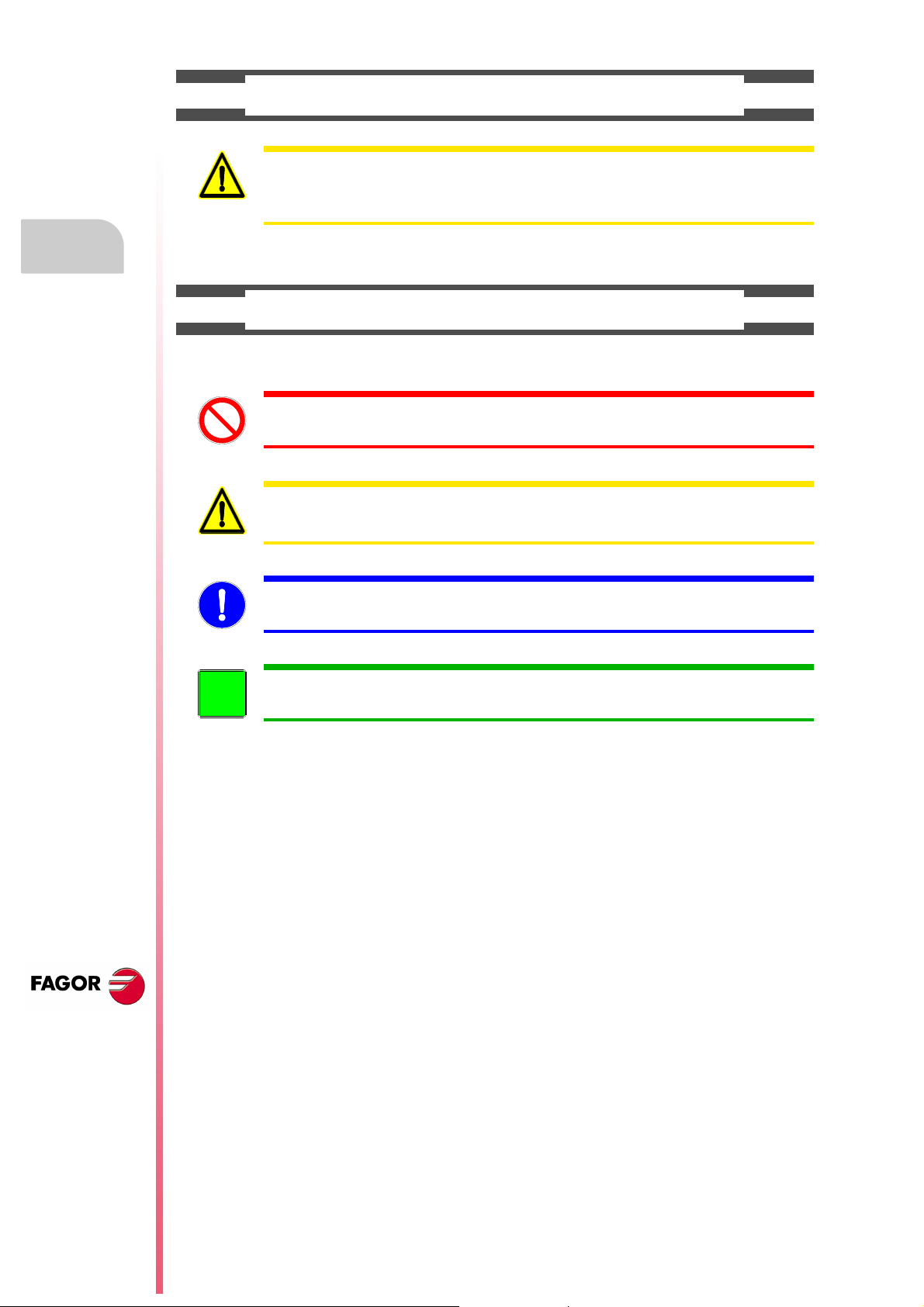
• Symbols which may appear on the manual.
Symbol for danger or prohibition.
It indicates actions or operations that may cause damage to people or to units.
Warning symbol.
It indicates situations that may be caused by certain operations and the actions to be taken to prevent
them.
Obligation symbol.
It indicates actions and operations that must be carried out.
Information symbol.
It indicates notes, warnings and advises.
CNC 8055
CNC 8055i
·18·

WARRANTY TERMS
INITIAL WARRANTY
All products manufactured or marketed by FAGOR carry a 12-month warranty for the end user which could
be controlled by the our service network by means of the warranty control system established by FAGOR
for this purpose.
In order to prevent the possibility of having the time period from the time a product leaves our warehouse
until the end user actually receives it run against this 12-month warranty, FAGOR has set up a warranty
control system based on having the manufacturer or agent inform FAGOR of the destination, identification
and on-machine installation date, by filling out the document accompanying each FAGOR product in the
warranty envelope. This system, besides assuring a full year of warranty to the end user, enables our service
network to know about FAGOR equipment coming from other countries into their area of responsibility.
The warranty starting date will be the one appearing as the installation date on the above mentioned
document. FAGOR offers the manufacturer or agent 12 months to sell and install the product. This means
that the warranty starting date may be up to one year after the product has left our warehouse so long as
the warranty control sheet has been sent back to us. This translates into the extension of warranty period
to two years since the product left our warehouse. If this sheet has not been sent to us, the warranty period
ends 15 months from when the product left our warehouse.
This warranty covers all costs of material and labour involved in repairs at FAGOR carried out to correct
malfunctions in the equipment. FAGOR under takes to repair or replace their products within the period from
the moment manufacture begins until 8 years after the date on which it disappears from the catalog.
FAGOR has exclusive competence in deciding whether the repair enters within the term defined as the
warranty period.
EXCLUDING CLAUSES
Repairs will be carried out on our premises. Therefore, all expenses incurred as a result of trips made by
technical personnel to carry out equipment repairs, despite these being within the above-mentioned period
of warranty, are not covered by the warranty.
Said warranty will be applied whenever the equipment has been installed in accordance with instructions,
has not be mistreated, has not been damaged by accident or by negligence and has not been tampered
with by personnel not authorized by FAGOR. If, once servicing or repairs have been made, the cause of
the malfunction cannot be attributed to said elements, the customer is obliged to cover the expenses
incurred, in accordance with the tariffs in force.
Other warranties, implicit or explicit, are not covered and FAGOR AUTOMATION cannot be held responsible
for other damages which may occur.
CNC 8055
CNC 8055i
·19·

WARRANTY ON REPAIRS
In a similar way to the initial warranty, FAGOR offers a warranty on standard repairs according to the
following conditions:
PERIOD
CONCEPT
EXCLUDING CLAUSES
When the customer does not choose the standard repair and just the faulty material has been replaced,
Warranty terms
the warranty will cover just the replaced parts or components within 12 months.
For sold parts the warranty is 12 moths length.
The SERVICE CONTRACT is available for the distributor or manufacturer who buys and installs our CNC
systems.
12 months.
Covers parts and labor for repairs (or replacements) at the network's own
facilities.
The same as those applied regarding the chapter on initial warranty.
If the repair is carried out within the warranty period, the warranty extension
has no effect.
MAINTENANCE CONTRACTS
CNC 8055
CNC 8055i
·20·

MATERIAL RETURNING TERMS
When sending the central nit or the remote modules, pack them in its original package and packaging
material. If the original packaging material is not available, pack it as follows:
1. Get a cardboard box whose three inside dimensions are at least 15 cm (6 inches) larger than those
of the unit. The cardboard being used to make the box must have a resistance of 170 kg. (375 pounds).
2. Attach a label indicating the owner of the unit, person to contact, type of unit and serial number.
3. In case of failure, also indicate the symptom and a short description.
4. Wrap the unit in a polyethylene roll or similar material to protect it.
5. When sending the central unit, protect especially the screen.
6. Pad the unit inside the cardboard box with polyurethane foam on all sides.
7. Seal the cardboard box with packing tape or industrial staples.
CNC 8055
CNC 8055i
·21·

Material returning terms
CNC 8055
CNC 8055i
·22·
ADDITIONAL REMARKS
FAGOR
I/O
X1
X2
X3
AXES
X1 X2
X3 X4
X5 X6
X7 X8
X9
X10
CPU
X1 X2
CMPCT
FLASH
ETH
COM1
X3
C
D
E
F
0
B
A
9
8
1
7
2
6
3
5
4
IN
OUT
NODE
USB
(A)
(B)
X1
W1
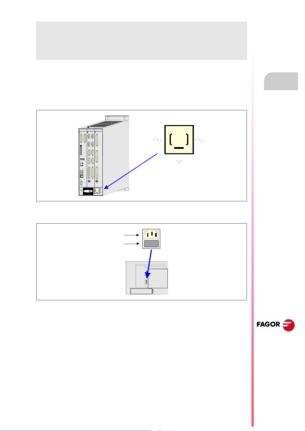
Mount the CNC away from coolants, chemical products, blows, etc. which could damage it. Before turning
the unit on, verify that the ground connections have been properly made.
To prevent electrical shock at the central unit of the 8055 CNC, use the proper mains AC connector at the
power supply module. Use 3-wire power cables (one for ground connection).
To prevent electrical shock at the monitor of the 8055 CNC, use the proper mains AC connector (A) with
3-wire power cables (one of them for ground connection).
Before turning on the monitor of the 8055 CNC and verifying that the external AC line (B) fuse of each unit
is the right one. See identification label of the unit itself.
In case of a malfunction or failure, disconnect it and call the technical service. Do not get into the inside
of the unit.
CNC 8055
CNC 8055i
·23·

Additional remarks
CNC 8055
CNC 8055i
·24·

FAGOR DOCUMENTATION
OEM manual
It is directed to the machine builder or person in charge of installing and starting-up the CNC.
USER-M manual
Directed to the end user.
It describes how to operate and program in M mode.
USER-T manual
Directed to the end user.
It describes how to operate and program in T mode.
MC Manual
Directed to the end user.
It describes how to operate and program in MC mode.
It contains a self-teaching manual.
TC Manual
Directed to the end user.
It describes how to operate and program in TC mode.
It contains a self-teaching manual.
MCO/TCO model
Directed to the end user.
It describes how to operate and program in MCO and TCO mode.
Examples-M manual
Directed to the end user.
It contains programming examples for the M mode.
Examples-T manual
Directed to the end user.
It contains programming examples for the T mode.
WINDNC Manual
It is directed to people using the optional DNC communications software.
It is supplied in a floppy disk with the application.
WINDRAW55 Manual
Directed to people who use the WINDRAW55 to create screens.
It is supplied in a floppy disk with the application.
CNC 8055
CNC 8055i
·25·

Fagor documentation
CNC 8055
CNC 8055i
·26·
8055 CNC CONFIGURATION
FAGOR
I/O
X1
X2
X3
AXES
X1 X2
X3 X4
X5 X6
X7 X8
X9
X10
CPU
X1 X2
CMPCT
FLASH
ETH
COM1
X3
C
D
E
F
0
B
A
9
8
1
7
2
6
3
5
4
IN
OUT
NODE
USB
FAGOR
I/O
X1
X2
X3
I/O
X1
X2
X3
I/O
X1
X2
X3
I/O
X1
X2
X3
AXES
X1 X2
X3 X4
X5 X6
X7 X8
X9
X10
CPU
X1 X2
CMPCT
FLASH
ETH
COM1
X3
C
D
E
F
0
B
A
9
8
1
7
2
6
3
5
4
IN
OUT
NODE
USB
1
The CNC is prepared to be used in industrial environments, especially on milling machines, lathes,
etc.
The CNC can control machine movements and devices.
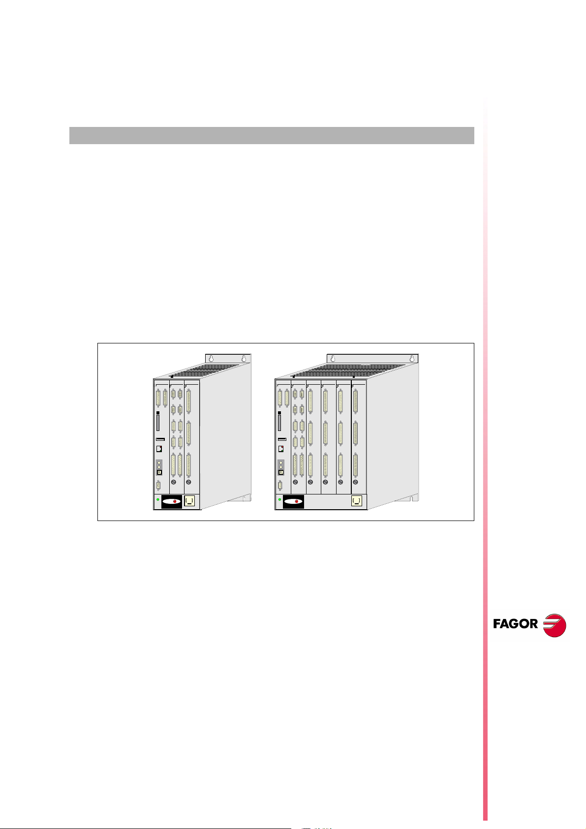
1.1 CNC structure
The CNC consists of the following elements:
• Central Unit.
•Monitor.
• Keyboard.
The central unit (CPU) has a modular structure. There are 2 models: for 3 and 6 modules.
Either separate keyboard and monitor or keyboards with an incorporated monitor are available.
The monitors are 11" LCD.
The keyboards are specific for each model and work mode.
CNC 8055
CNC 8055i
SOFT: V01.4X
·27·

1.
FAGOR
I/O
X1
X2
X3
AXES
X1 X2
X3 X4
X5 X6
X7 X8
X9
X10
CPU
X1 X2
CMPCT
FLASH
ETH
COM1
X3
C
D
E
F
0
B
A
9
8
1
7
2
6
3
5
4
IN
OUT
NODE
USB
FAGOR
I/O
X1
X2
X3
I/O
X1
X2
X3
I/O
X1
X2
X3
I/O
X1
X2
X3
AXES
X1 X2
X3 X4
X5 X6
X7 X8
X9
X10
CPU
X1 X2
CMPCT
FLASH
ETH
COM1
X3
C
D
E
F
0
B
A
9
8
1
7
2
6
3
5
4
IN
OUT
NODE
USB
FAGOR
0
2
4
10
20
30
405060
70
80
90
100
110
120
FEED %SPINDLE
JOG
100
10
1
110100
1000
10000
8055-M
11" LCD
FAGOR
0
2
4
10
20
30
4050
60
70
80
90
100
110
120
FEED %
SPINDLE
JOG
100
10
1
1
1010 0
1000
10000
8055-MC
11" LCD
FAGOR
0
2
4
10
20
30
405060
70
80
90
100
110
120
FEED %SPINDLE
JOG
100
10
1
110100
1000
10000
8055-T
11" LCD
FAGOR
0
2
4
10
20
30
405060
70
80
90
100
110
120
FEED %SP INDLE
JOG
100
10
1
110100
1000
10000
8055-TC
11" LCD
MONITOR-55M-11-USB
(CUSTOMTY=254)
MONITOR-55MC-11-USB
(CUSTOMTY=254)
MONITOR-55T-11-USB
(CUSTOMTY=254)
MONITOR-55TC-11-USB
(CUSTOMTY=254)
FAGOR
JOG
100
10
1
110100
1000
10000
0
2
4
10
20
30
405060
70
80
90
100
110
120
FEED %
8055-MC
FAGOR
JOG
100
10
1
1
10100
1000
10000
0
2
4
10
20
30
405060
70
80
90
100
110
120
FEED %
8055-M/T
FAGOR
JOG
100
10
1
110100
1000
10000
0
2
4
10
20
30
405060
70
80
90
100
110
120
FEED %
8055-TC
FAGOR
JOG
100
10
1
110100
1000
10000
0
2
4
10
20
30
405060
70
80
90
100
110
120
FEED %
8055-MCO/TCO
OP.804 0/55.A LFA
(CUSTOMTY=25 2)
OP.804 0/55M C
(CUSTOMTY=0)
OP.804 0/55T C
(CUSTOMTY=0)
OP.8040/55MCO/TCO
(CUSTOMTY=0)
+
+
+
FAGOR
11" LCD
MONITOR-8 055
KB.40/55.ALFA
+
KS 50/55
Option
Installation manual
The following illustration shows the possible combinations. Each configuration shows the value of
machine parameter CUSTOMTY (P92).
CNC structure
8055 CNC CONFIGURATION
CNC 8055
CNC 8055i
SOFT: V01.4X
·28·
Use the video signal cable (up to 40 m) to connect the monitor with the central unit and the keyboard
signal cable (up to 25 m) to connect the keyboard with the central unit.
Keyboard auto-identification
Certain keyboard models have a auto-identification system. With this type of keyboards, parameter
CUSTOMTY is updated automatically; for the rest of the keyboards, this parameter must be set
manually.
If the keyboard does not match the CNC model, it shows the relevant error message and it loads
the key codes that correspond to the CNC model. For example, if a mill model keyboard is connected
to a lathe CNC, the keyboard is set for a lathe and the CNC shows the error message.
Installation manual
FAGOR
I/O
X1
X2
X3
I/O
X1
X2
X3
I/O
X2
X3
I/O
X1
X2
X3
AXES
X1 X2
X3 X4
X5 X6
X7 X8
X9
X10
CPU
X1 X2
CMPCT
FLASH
ETH
COM1
X3
C
D
E
F
0
B
A
9
8
1
7
2
6
3
5
4
IN
OUT
NODE
USB
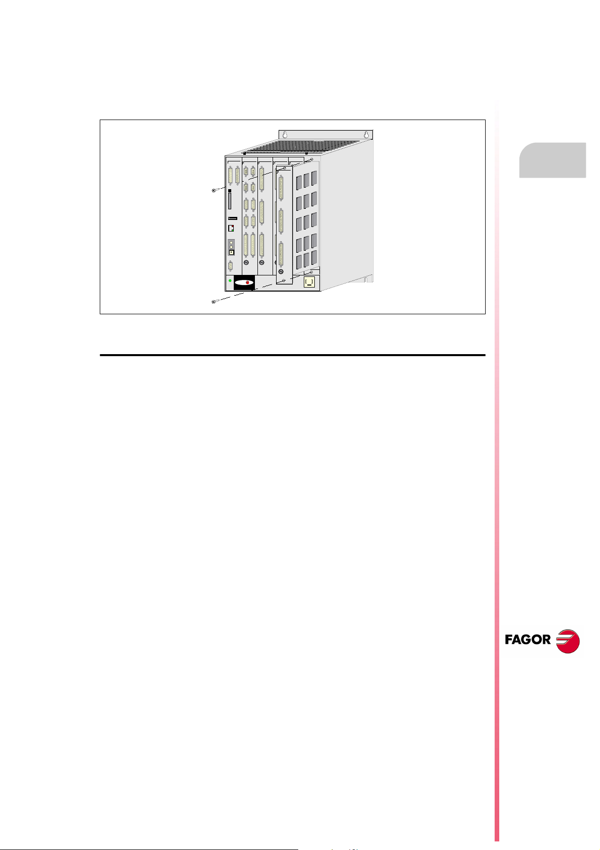
1.2 Central unit
The central unit is usually located in the electrical cabinet, is modular and it comes in two models:
There are 2 models: for 3 and 6 modules.
The modules are mounted using the screws located at their top and bottom.
1.
Central unit
8055 CNC CONFIGURATION
Available modules
CPU
It contains the system software and carries out the CNC functions (editing, execution, simulation,
display, etc.), process the information of the rest of the modules and generate the video signals for
the monitor.
Optionally, it communicates with the drives via Sercos interface.
It must be part of all the configurations and mounted as the first module from the left.
Axes:
Besides controlling the spindle and the axes of the machine, it governs the first 40 digital PLC inputs
and 24 digital PLC outputs.
It must be present in all configurations. Together with the –CPU– module makes up the basic system
configuration.
I/Os
It is optional. It offers another 64 digital PLC inputs and 32 digital PLC outputs.
CNC 8055
CNC 8055i
SOFT: V01.4X
·29·

1.
I/O
X1
X2
X3
1
2
3
4
ON
OFF
Central unit
8055 CNC CONFIGURATION
Installation manual
Central Unit (CPU) configuration
The configuration of the central unit depends on each application. The –CPU– and –AXES– modules
must be part of all configurations.
The –CPU– module must be the first one from the left. The rest of the modules do not have to follow
a particular order and may be interchanged according to personal preferences and connection
possibilities of the machine.
The CNC has a PLUG&PLAY system that recognizes the configuration of the central unit. To do that,
regardless of their physical location, each module has a logic address or device select code which
identifies it within the internal configuration of the CNC. The logic address (device select code) for
each module is factory set as follows:
–Axes– module Logic address 2.
–I/Os– (1) module Logic address 3.
–I/Os– (2) module Logic address 4.
–I/Os– (3) module Logic address 5.
Nevertheless, except in the axes module, these logic addresses may be modified at will. To do that,
use the microswitches located in one of the corners of the printed circuit board.
CNC 8055
CNC 8055i
SOFT: V01.4X
The logic address is set in binary code between 1 and 14. Logic address "0" and "15" are reserved.
Logic addresses 0 and 15 are reserved.
Logic
address
0 off off off off 8 on off off off
1 off off off on 9 on off off on
2 off off on off 10 on off on off
3 off off on on 11 on off on on
4 off on off off 12 on on off off
5 off on off on 13 on on off on
6 off on on off 14 on on on off
7 off on on on 15 on on on on
Micro switch position Logic
1 2 3 4 1 2 3 4
address
Micro switch position
When using several –I/O– modules, the CNC assumes the one with the lowest address as the first
expansion module, as –I/O– (2) module the next address and as –I/O– (3) the one with the highest
address number.
·30·
 Loading...