

Page 1
Operating Manual
(MCO & TCO options)
Ref. 0204-ing
Page 2
The information described in this manual may be subject to variations
due to technical modifications.
FAGOR AUTOMATION, S.Coop. Ltda. reserves the right to modify
the contents of the manual without prior notice.
iii
Page 3

INDEX
1. GENERAL CONCEPTS
1.1 "M/T" and "CO" work modes ...................................................................................1
1.2 Keyboard ..................................................................................................................2
1.3 Keyboard customizing ..............................................................................................4
2. OPERA TING IN JOG MODE
2.1 Introduction ..............................................................................................................2
2.2 Axis Control .............................................................................................................6
2.2.1 Work Units ................................................................................................................6
2.2.2 Coordinate preset ......................................................................................................6
2.2.3 Handling the Feedrate of the Axes (F) ......................................................................6
2.3 Home search (Machine reference zero) .....................................................................7
2.4 Jogging the axes .......................................................................................................8
2.4.1 Jogging to a programmed position...........................................................................8
2.4.2 Incremental jog .........................................................................................................8
2.4.3 Continuous jog .........................................................................................................9
2.4.4 Jogging with an Electronic Handwheel....................................................................10
2.4.4.1 Standard handwheel mode.........................................................................................11
2.4.4.2 Path handwheel mode...............................................................................................12
2.4.4.3 Feed handwheel ........................................................................................................13
2.5 Tool control ..............................................................................................................14
2.5.1 Single tool change point ..........................................................................................14
2.5.2 Variable tool change point .......................................................................................15
2.5.3 Live tool ...................................................................................................................16
2.6 Spindle Control ........................................................................................................18
2.6.1 Spindle in RPM ........................................................................................................19
2.6.2 Constant Surface Speed ............................................................................................20
2.6.2.1 Operating at Constant Surface Speed (CSS) .............................................................21
2.7 Handling ISO code....................................................................................................22
v
Page 4

3. OPERATING WITH OPERATIONS OR CYCLES
3.1 Associated programs .................................................................................................3
3.2 Associated routines ...................................................................................................3
3.3 OEM cycles...............................................................................................................4
3.3.1 Screen definition .......................................................................................................4
3.3.2 Configuration file .....................................................................................................5
3.3.3 Associated routine ....................................................................................................9
3.3.4 Error log file (P999500) ............................................................................................11
3.4 Access to OEM cycles from the PLC ........................................................................12
3.5 Cycle data entry ........................................................................................................13
3.6 Simulation and execution .........................................................................................14
3.7 Background cycle editing ........................................................................................14
3.8 Positioning cycle ......................................................................................................15
3.8.1 Definition of data......................................................................................................16
3.8.2 Definition of spindle conditions ..............................................................................17
3.8.3 Definition of machining conditions .........................................................................17
4. PROGRAM STORAGE
4.1 List of stored programs .............................................................................................2
4.2 See content of a program ..........................................................................................3
4.2.1 Seeing one of the cycles in detail .............................................................................3
4.3 Edit a new part-program............................................................................................4
4.3.1 Storage of an ISO block or a cycle............................................................................4
4.4 Erasing a part-program..............................................................................................5
4.5 Copy a part-program in another................................................................................5
4.6 Modifying a part-program ........................................................................................6
4.6.1 Erasing an operation .................................................................................................6
4.6.2 Moving an operation to another position ................................................................6
4.6.3 Adding or inserting a new operation ........................................................................7
4.6.4 Modifying an already existing operation .................................................................7
5. EXECUTION AND SIMULA TION
5.1 Simulating or executing an operation or cycle ........................................................2
5.2 Simulating or executing a part-program...................................................................3
5.2.1 Simulating or executing a section of a part-program ................................................3
5.3 Simulating or executing a stored operation .............................................................3
5.4 Execution Mode .......................................................................................................4
5.4.1 Tool inspection .........................................................................................................5
5.5 Graphics ....................................................................................................................6
vi
Page 5
MCO-TCO work mode
1. GENERAL CONCEPTS
1.1 "M/T" AND "CO" WORK MODES
The CNC offers all the features of the M/T models plus those specific of the CO mode.
There are 2 work modes. M/T and CO.
This manual is for the CO mode.
The "M" and "T" modes (described in the Installation, Operation and Programming manuals) must
be used to:
• set up the machine
• edit the PLC program
• customize screens
• customize canned cycles
• eliminate certain CNC errors
• etc.
The CO mode, the machine manufacturer can:
• customize the keyboard (see this chapter)
• modify the CNC screens (see "Screen customizing" in the Installation manual)
• design machining operations and canned cycles (see chapter on "working with operations
or cycles)
• create screens for diagnosis, setup, to show the status of the CNC-PLC, etc.
This manual describes how to operate with the basic or standard Fagor features and it is up to the
manufacturer to document all the modifications and new cycles created by him/her.
After turning on the CNC and after the keystroke sequence: the CNC displays the
standard display of the selected work mode.
Use the keystroke sequence: to toggle between the CO and M/T modes.
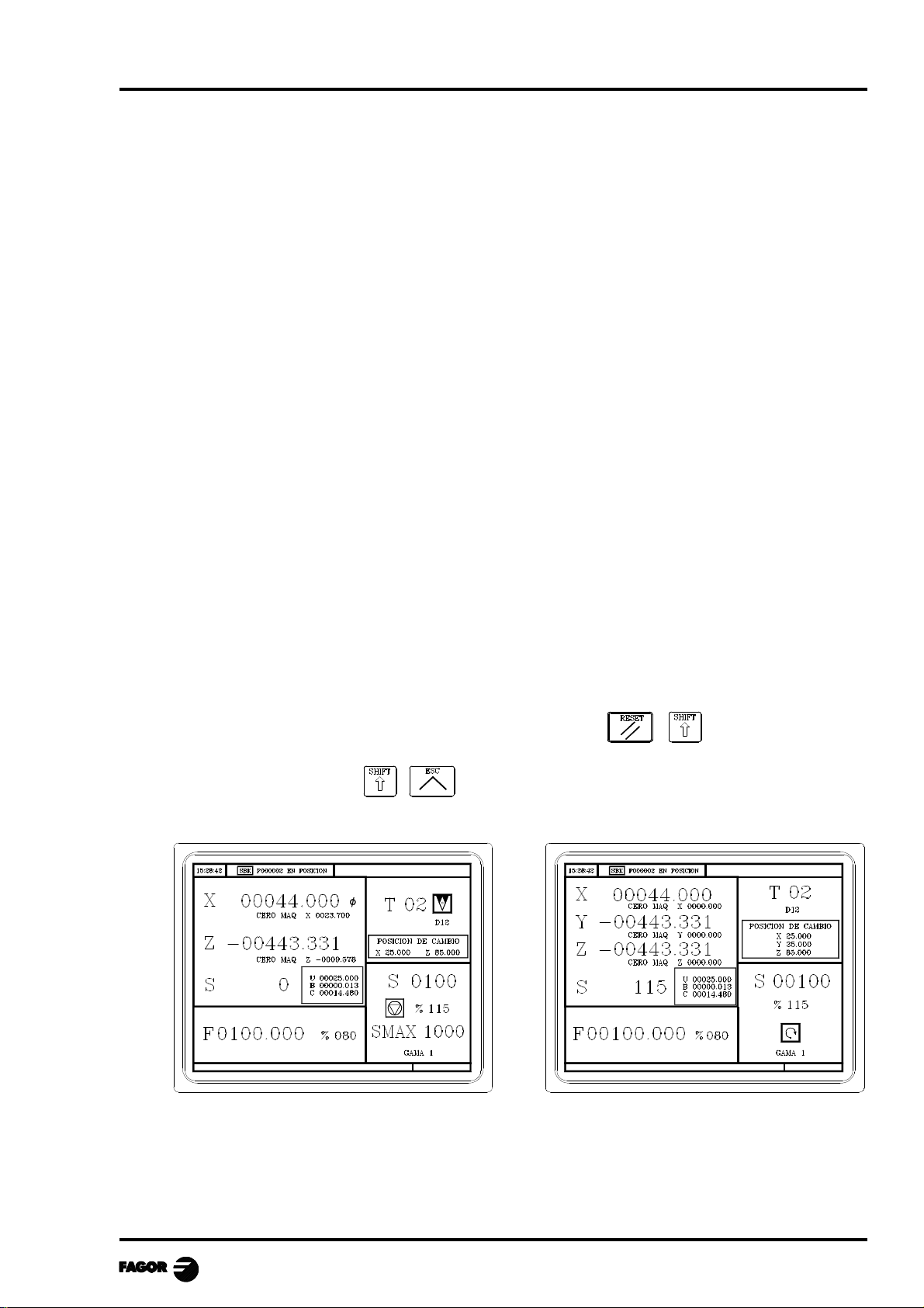
The standard CO mode screen depends on the model:
TCO Model MCO Model
To edit (modify or replace) this screen, refer to the chapter on "Screen customizing" in the Installation
manual.
Chapter 1 - page 1
Page 6
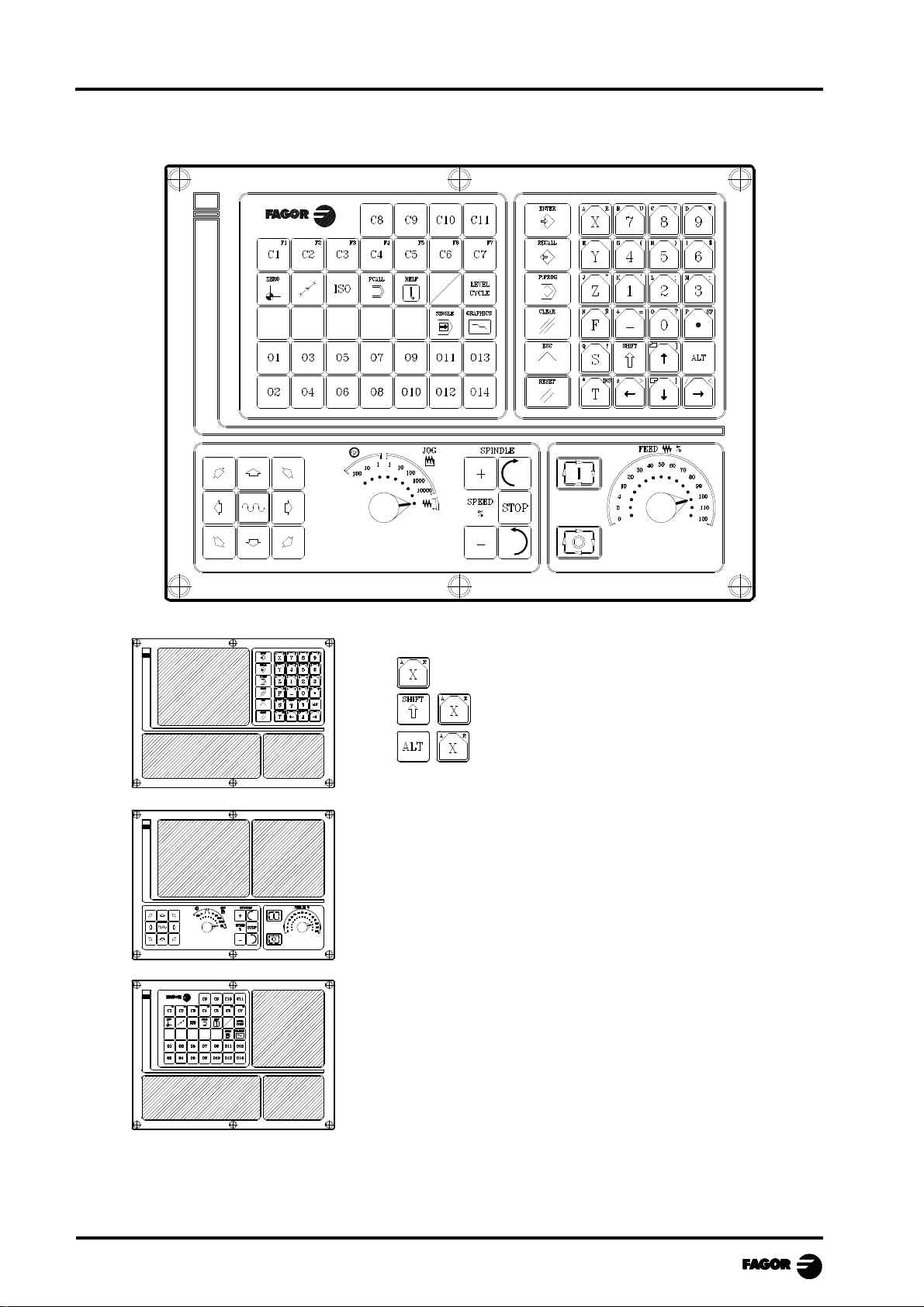
1.2 KEYBOARD
MCO-TCO work mode
Alphanumeric keyboard and command keys.
Selects the X character
Selects the A character
Selects the R character
JOG keyboard
To: jog the axes of the machine
Govern the spindle
Modify axes feedrate and spindle speed
Start and stop program execution
Specific keys of the CO model
To: Select and define the machining operations
Control external devices
Select the graphic representation
Select either the single or automatic execution mode
Chapter 1 - page 2
Page 7
MCO-TCO work mode
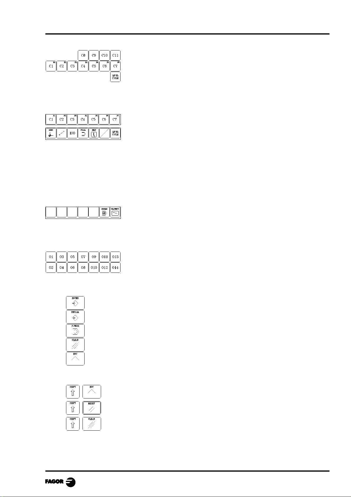
Keys related to the operations or canned cycles.
User C1 to access cycle 1, C2 for cycle 2 and son on.
Each key may have up to 10 levels or variations which are selected by
means of the [LEVEL CYCLE] key. For example:
C1 => Cycle 1, +Level => Cycle 21, +Level => Cycle 41, ....
When pressing keys C1 through C11, the CNC recovers the last cycle
(level) used in each group.
Keys C1 through C11 may be customized by the manufacturer by
inserting printed strips through slots on the back of the keyboard.
Keys which act as softkeys F1 through F7 in M/T mode.
Specific keys for the CO mode. From left to right, they are used for:
• Homing the axes of the machine (see chapter on "operating in Jog
mode").
• Executing the positioning cycle (see chapter on "working with
operations or cycles).
• Managing ISO and MDI (see chapter on "operating in Jog mode").
• PCALL to see the screens of cycles created by the manufacturer (see
chapter on "working with operations or cycles).
• HELP (for the M/T mode).
• Selecting different states in particular cycles or screens.
• Select different levels in each cycle.
The blank keys are free and may be customized by the manufacturer by
Free keys, usually to control external devices.
They may be customized by the manufacturer by inserting printed strips
This chapter describes how to handle these keys.
Command keys.
For the CNC to assume the edited value.
To recall data, cycles or blocks from memory.
To access program storage (see chapter on program storage)
Depending on the data, to delete the last character entered or the whole program.
To quit the selected operation, cycle or mode.
Special keystroke sequences:
inserting printed strips through slots on the back of the keyboard. This
chapter describes how to handle these keys.
The SINGLE key allows executing or simulating a program step by step.
The GRAPHICS key allows simulating a cycle or viewing the graphic
representation of the tool movements while executing a program.
through slots on the back of the keyboard.
To toggle between CO and M/T modes.
To reset the CNC. It is the same as turning the CNC off and back on.
Cancels the video signal (the screen goes blank). Press any key to restore the image.
Chapter 1 - page 3
Page 8
MCO-TCO work mode
1.3 KEYBOARD CUSTOMIZING
The external devices must be turned on or off by the machine manufacturer by means of a PLC
program.
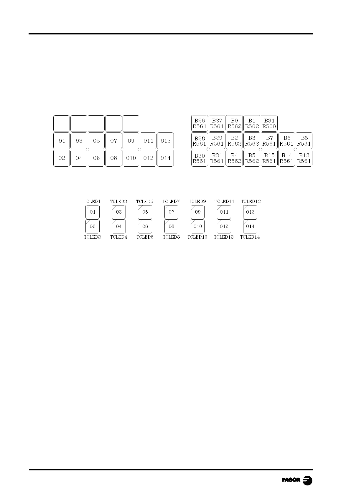
The CNC will inform the PLC on the status of each key. The pertinent register bit will be set to "1"
when the key is pressed and "0" when it is not.
The register bit for each key is the following:
keys O1 through O14 have an indicator lamp. The status of each key lamp must be controlled by the
machine manufacturer with a PLC program using the TCLED* input variables shown below.
Examples:
The O1 key is used to control the coolant
DFU B28R561 = CPL TCLED1
= CPL O33
To turn on the device controlled with the O2 key, a number of conditions must be met
DFU B30R561 AND (Rest of conditions) = CPL TCLED2
= CPL O34
Chapter 1 - page 4
Page 9
MCO-TCO work mode
2. OPERA TING IN JOG MODE
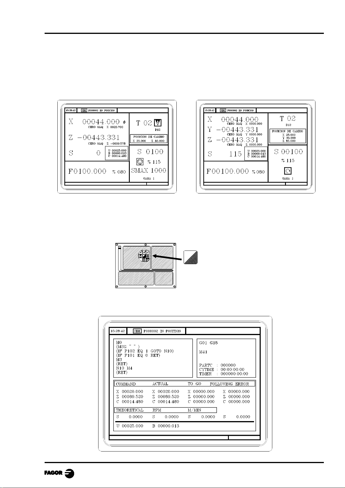
The standard screen for the CO operating mode dpends on the model:
TCO model MCO model
La forma de operar con ambos modelos es muy parecida. Si algunas de las prestaciones descritas en
este capítulo no es común para ambos modelos, se indicará claramente a qué modelo corresponde.
If one presses key
The CNC displays the auxiliary screen for the CO operating.
Chapter 2 - page 1
Page 10
MCO-TCO work mode
2.1 INTRODUCTION
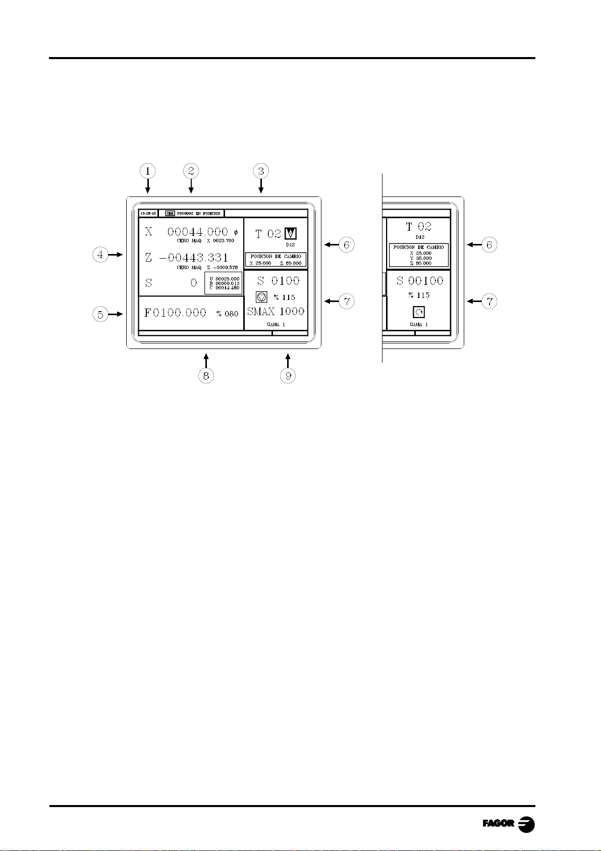
The standard screen for the CO operating mode may be entirely customized (see "screen customizing"
in the installation manual).
The one supplied by Fagor contains the following information:
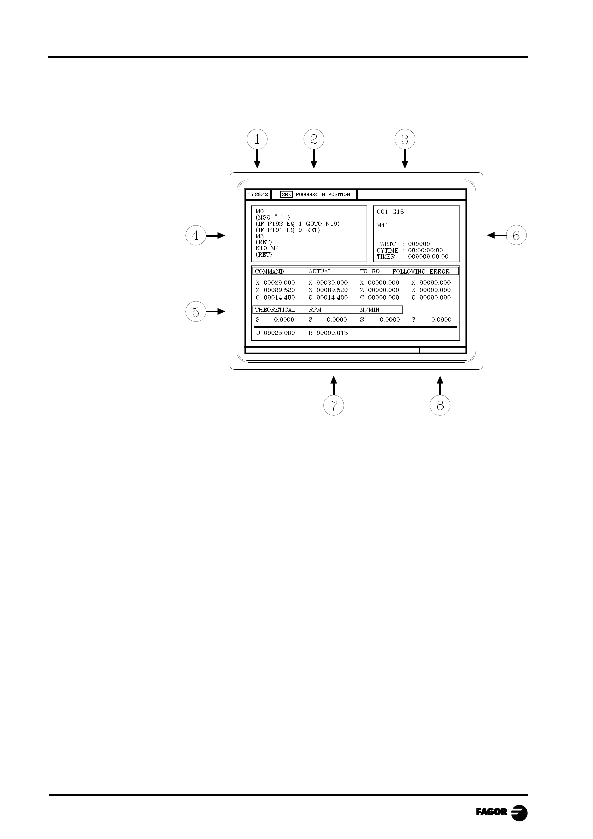
1.- Clock
2.- This window can display the following data:
SBK when the Single Block execution mode is selected.
DNC when the DNC mode is activated.
P..... number of the program selected.
Message «In Position» - «Execution» - «Interrupted» - «RESET»
PLC messages
3.- The CNC messages are shown in this window.
4.- This screen may be entirely customized (see "screen customizing" in the installation manual).
The one supplied by Fagor can display the following data:
* The coordinates of the axes. The ? symbol indicates that the axis is working in diameters.
* When defining the text 33 of program 999997, the screen will show the axes coordinates
referred to machine reference zero (home) in small characters.
* The real spindle rpm "S".
* In a box, the coordinates of the auxiliary axes that are defined.
5.- This window may be customized entirely (see "Screen customizing" in the installation manual).
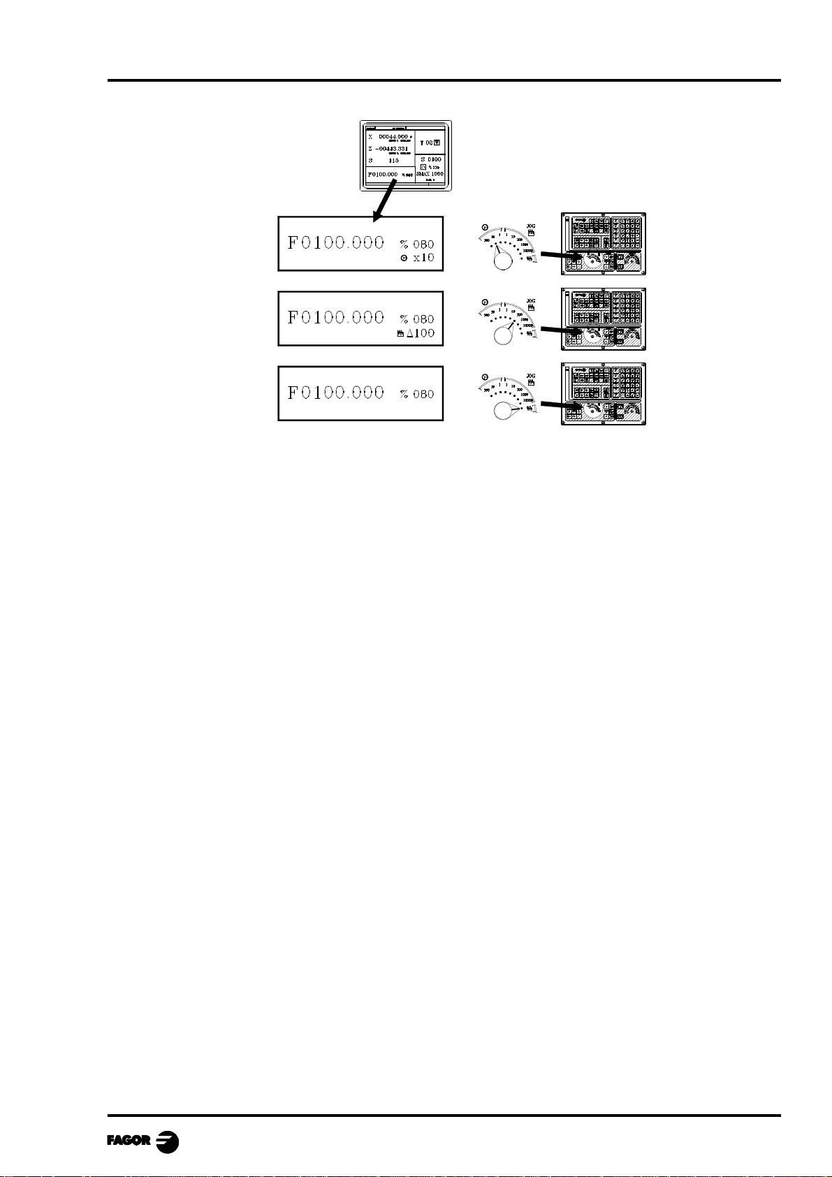
The one supplied by Fagor shows the feedrate of the «F» axes that has been selected and the %
of F which is being applied are shown.
When Feed-hold is active, the feedrate value changes colors.
On the other hand, depending on the position occupied by the left switch, it can show the
following information:
Chapter 2 - page 2
Page 11
MCO-TCO work mode
6.- This screen may be entirely customized (see "screen customizing" in the installation manual).
The one supplied by Fagor shows everything about the tool.
* The number of the tool currently selected (in large characters).
* The graphic representation corresponding to the location code associated with the tool.
* The offset number «D» associated with the tool. If the tool number and the offset number
coincide, the CNC will not display value «D».
* The coordinates for the tool change point referred to home. The CNC does not display this
window when text 47 of program 999997 is not defined.
7.- This window may be customized entirely (see "Screen customizing" in the installation manual).
The one supplied by Fagor shows everything about the spindle :
* The theoretical turning speed selected. «S» value when working in rpm. and the «CSS» value
when working in TCO mode at constant surface speed.
* The condition of the spindle. This is represented by an icon and can be turning to the right,
to the left or idle.
* The % of the spindle speed being applied.
* The maximum spindle rpm (TCO model).
* The range of spindle active.
* The range of the active spindle. The CNC does not display this information when text 28 of
program 999997 is not defined.
8.- Whenever a work cycle is accessed, the CNC shows the help text associated with the icon
selected in this window.
This help text must be defined in P999994 program and be written in the language required.
The format and the points to be considered in the P999994 program are detailed in the chapter
on "General Concepts".
9.- Reserved.
Chapter 2 - page 3
Page 12
MCO-TCO work mode
The auxiliary screen for the CO operating mode may be customized entirely (see "Screen
customizing" in the installation manual).
The one supplied by Fagor contains the following information:
1.- Clock
2.- This window can display the following data:
SBK when the Single Block mode of execution is selected.
DNC when the DNC mode is active.
P..... number of the program selected.
Message «In Position» - «Execution» - «Interrupted» - «RESET»
PLC messages
3.- The CNC messages are shown in this window.
4.- In manual operating mode this window does not display any data, but during execution, it shows
the lines of the program being executed.
5.- The axes have the following fields:
COMMAND States the coordinate programmed, that is, the position that the axis must
reach.
ACTUAL States the actual coordinate or actual position of the axis.
TO GO States the distance that the axis has still to go to reach the coordinate
programmed.
FOLLOWING ERROR Difference between the theoretical and real values of the position.
The spindle (S) has the following fields available:
THEORETICAL theoretical speed S programmed.
RPM speed in rpm.
M/MIN speed in meters/ minute.
FOLLOWING ERROR When operating with spindle guided stop (M19) this indicates the
difference between theoretical and real speeds.
The auxiliary axes only show the actual position of the axis
Chapter 2 - page 4
Page 13
MCO-TCO work mode
6.- This window shows the status of the «G, F, T, D, M» functions and the value of the variables.
PARCO States the number of consecutive parts that have been executed with the same
program.
Whenever a new program is selected, this variable assumes value 0.
CYTIME States the time elapsed during the execution of the parts. It is expressed in the
following format: “hours : minutes : seconds : hundredths of second”.
Whenever the execution of a program is started, even though this is repetitive, this
variable assumes value 0.
TIMER States the reading of the clock enabled by the PLC. It is expressed in format “hours
: minutes : seconds”.
7.- Reserved.
8.- Reserved.
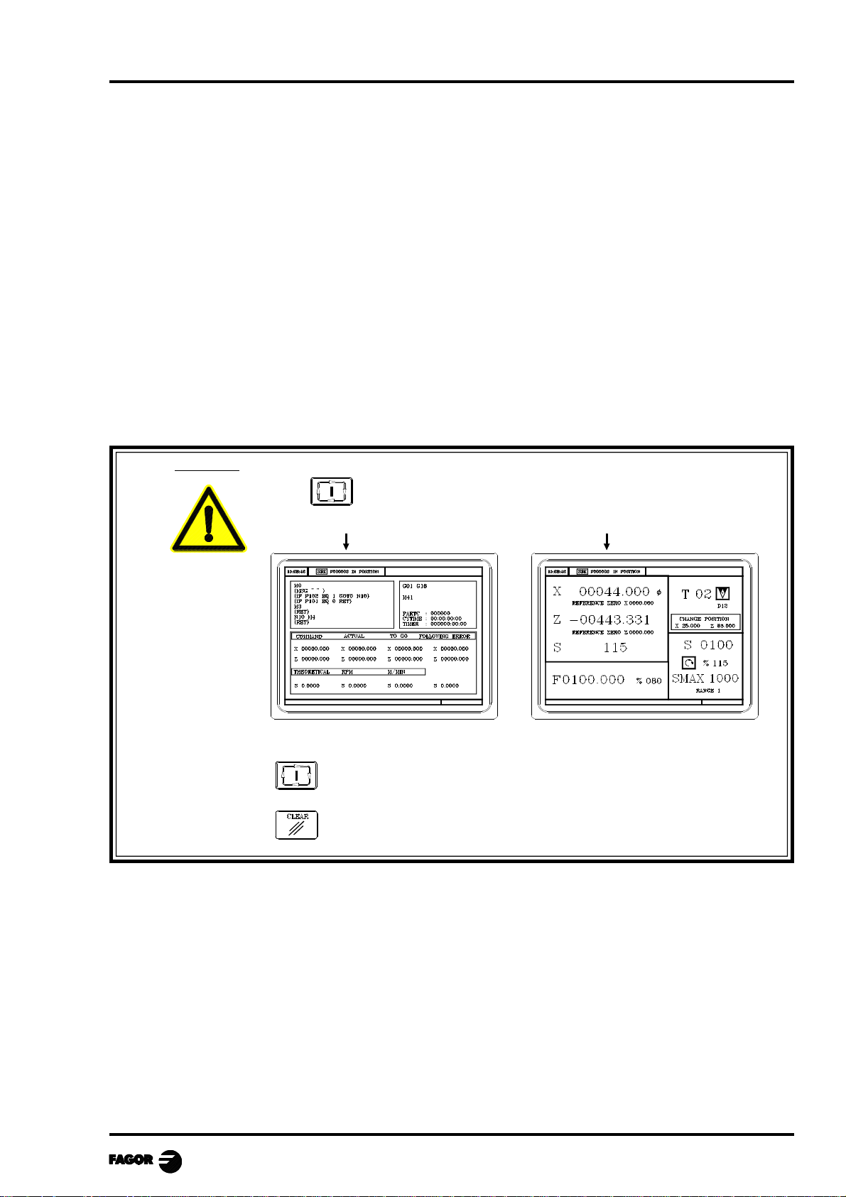
Warning
The symbol appears in the middle of the top window when there is
a part-progam selected to be executed or simulated.
In these cases, whn pressing:
the CNC executes the selected part-program.
it is de-selected, the CNC deletes the icon from the top center window.
Chapter 2 - page 5
Page 14
MCO-TCO work mode
2.2 AXIS CONTROL
2.2.1 WORK UNITS
Whenever the CO work mode is accessed, the CNC assumes the work units, «mm or inches», «radii
or diameters», «millimeters/minute or millimeters/revolution», etc., that are selected by machine
parameter.
To modify these values, the "T" mode has to be accessed, modifying the relevant machine parameter.
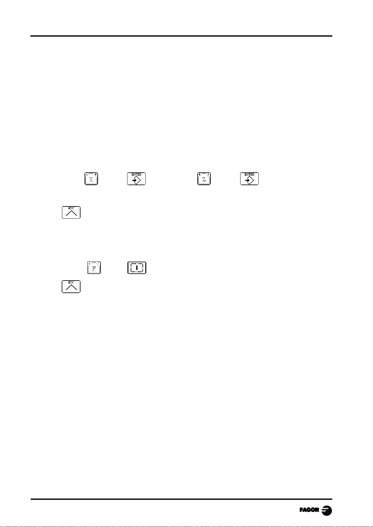
2.2.2 COORDINATE PRESET
The axes must be preset one at a time with the following procedure:
Value Value
The CNC requests confirmation of the command.
Press to quit the presetting mode.
2.2.3 HANDLING THE FEEDRATE OF THE AXES (F)
To set a particular axis feedrate, proceed as follows:
Value
Press to quit the selection.
Chapter 2 - page 6
Page 15
MCO-TCO work mode
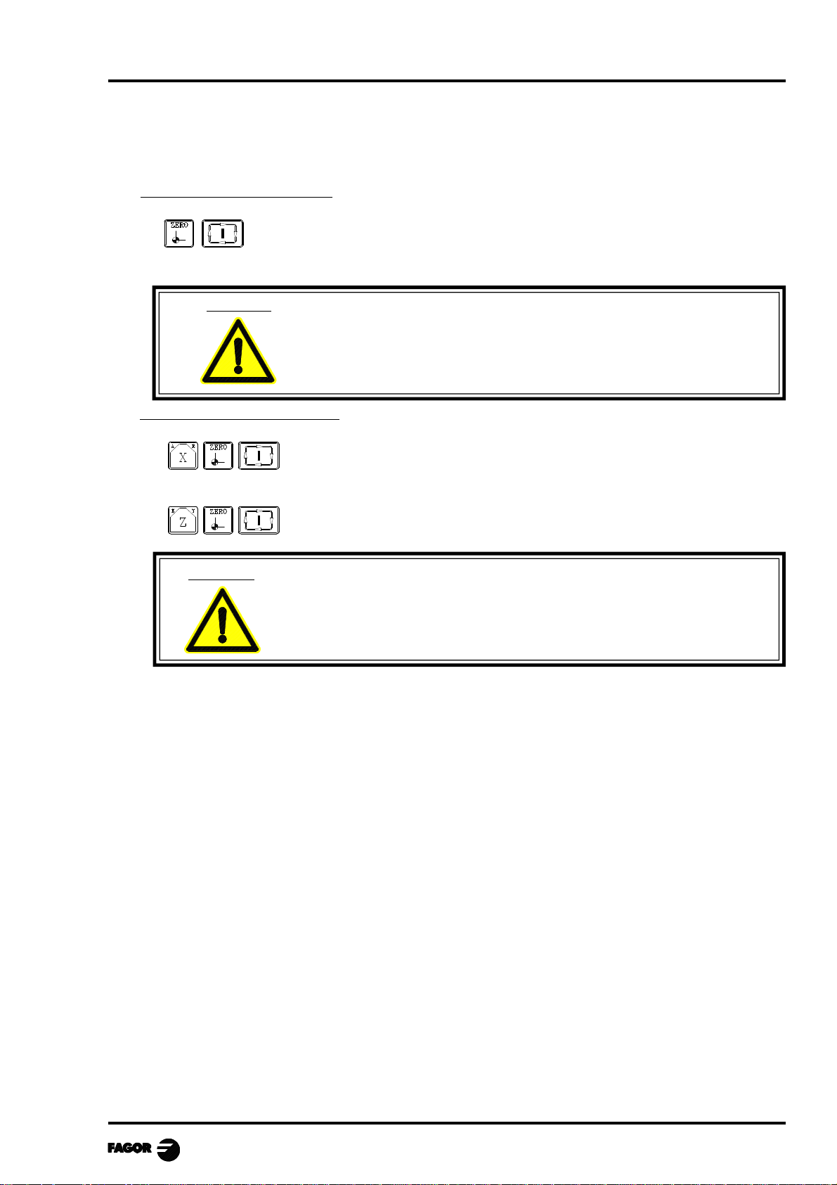
2.3 HOME SEARCH (MACHINE REFERENCE ZERO)
Home search can be done in 2 ways:
Home search on all the axes
The CNC will execute the machine reference zero routine defined by the
manufacture in the general machine parameter P34 (REFPSUB).
Warning: The CNC saves the part zero or zero offset that is active at the time.
If no home searching subroutine is defined, the CNC will display the
relevant error message.
Home search on a single axis
Carries out the home search on the X axis
Carries out the home search on the Z axis
Warning: The CNC does not save the part zero or zero offset that is active at the
time and assumes as new part zero the position taken by machine
reference zero (home).
Chapter 2 - page 7
Page 16
MCO-TCO work mode
2.4 JOGGING THE AXES
The axes of the machine can be moved in the following ways:
- continuous jog
- incremental jog
- jogging with an electronic handwheel
- jogging to a programmed position
2.4.1 JOGGING TO A PROGRAMMED POSITION
The movement is carried out one axis at a time. With the feedrate «F» and at the selected %.
Position Position
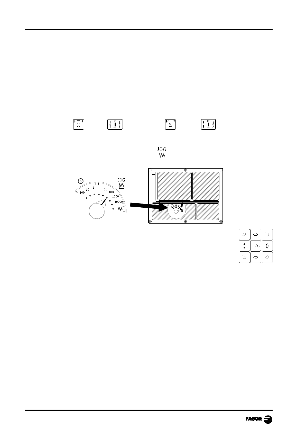
2.4.2 INCREMENTAL JOG
Place the left-hand switch in one of the positions
Incremental movement must be done axis to axis. To do this press the JOG key for
the direction of the axis to be moved.
Each time a key is pressed, the corresponding axis moves the amount set by the
switch. This movement effects the «F» feedrate selected.
Position of the switch Movement per turn
1 0.001 mm or 0.0001 inches
10 0.010 mm or 0.0010 inches
100 0.100 mm or 0.0100 inches
1000 1.000 mm or 0.1000 inches
10000 10.000 mm or 1.0000 inches
Chapter 2 - page 8
Page 17
MCO-TCO work mode
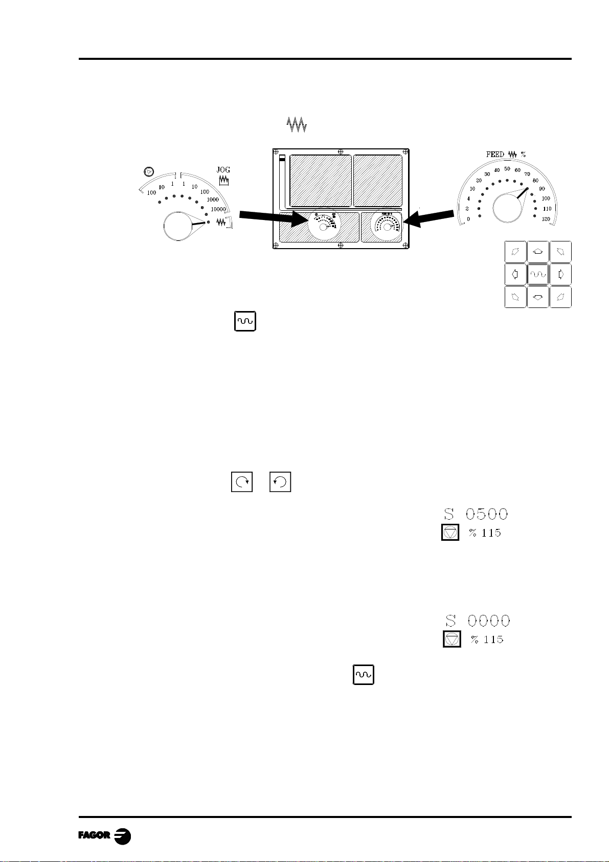
2.4.3 CONTINUOUS JOG
Place the left-hand switch in position and on the right-hand switch select the percentage (0%
to 120%) of the feedrate selected to be applied.
Continuous movement should be done axis to axis. To do this press the JOG
key for the direction of the axis to be moved.
The axis moves with a feedrate equal to the percentage (0% to 120%) of the «F»
feedrate selected.
If during movement the key is pressed the maximum feedrate possible is carried out, as is stated
in the “G00FEED” axis machine parameter. This feedrate will be applied as long as said key is
pressed, and when released the previous feedrate will be resumed.
Depending on the value assigned to general logic input “LACOHM”, the movement will be made
in one of the following ways:
* The axis will only move while the relevant JOG key is pressed.
* The axis will start moving when the JOG key is pressed and will not stop until said JOG key
or another JOG key is pressed again, and in this case the movement is transferred to what is
indicated by the next key pressed.
When operating with feedrate "F" in millimeters/revolution the following cases may arise:
a) The spindle is started. or
The CNC moves the axes to the F programmed.
b) The spindle is stopped but there is a spindle speed S selected.
Feature available at the TCO model when working with G95.
The CNC calculates the feedrate in millimeters/minute corresponding to the theoretical "S" and
moves the axis.
For example, if «F 2.000» and «S 500»:
Feedrate = F (mm/rev.) x S (rev/min)= 2 x 500 = 1000 mm/min
The axis moves at a feedrate of 1000 in millimeters/minute.
c) The spindle is stationary and there is no spindle speed S selected.
Feature available at the TCO model when working with G95.
The axes will only move in rapid and only if the key and the relevant axis key are pressed.
Chapter 2 - page 9
Page 18
MCO-TCO work mode
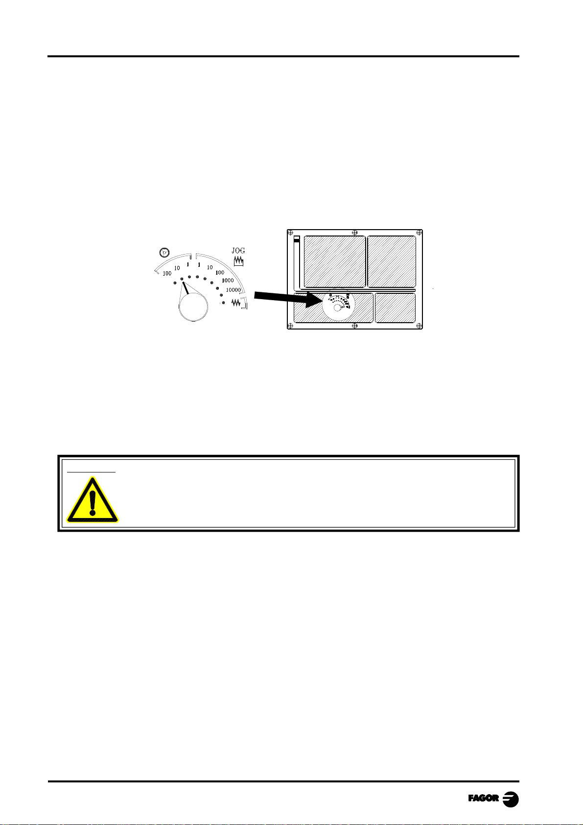
2.4.4 JOGGING WITH AN ELECTRONIC HANDWHEEL
The various handwheel configurations are:
General handwheel It can be used to jog any axis one by one.
Select the axis and turn the handwheel to move it.
Individual handwheel: It replaces the mechanical handwheels.
Up to 3 handwheels can be used (one per axis).
It only moves the axis it is associated with.
To move any of them, turn the switch to any of the handwheel positions.
Positions 1, 10 and 100 indicate the multiplying factor being applied besides the internal x4 to
the feedback pulses supplied by the electronic handwheel.
For example, if the manufacturer has set a distance of 0.100 mm or 0.0100 inches per handwheel
turn, thus:
Switch position Distance per turn
1 0.100 mm or 0.0100 inch
10 1.000 mm or 0.1000 inch
100 10.000 mm or 1.0000 inch
Warning:
When operating with individual handwheels and depending on how fast the handwheel
is turned and on the selected handwheel switch position, the CNC might be demanded
to move the axis faster than the maximum permitted. In that case, the CNC will move
the axis the indicated distance but it will limit the axis speed to that maximum value.
There are 3 operating modes with handwheels:
Standard handwheel:
With the general handwheel, select the axis to be moved and turn the
handwheel.
With individual handwheels, turn the handwheel associated with the axis to be
moved.
Path handwheel: For chamfering and rounding corners.
Feed handwheel To control the feedrate of the machine.
Chapter 2 - page 10
2 axes are moved along a selected path (chamfer or rounding) by moving a
single handwheel.
This feature must be activated via PLC.
The general handwheel is assumed as the "path handwheel" or the individual
handwheel associated with the X axis (MCO model) or Z (TCO model).
This feature must be activated via PLC.
Page 19

MCO-TCO work mode
2.4.4.1 STANDARD HANDWHEEL MODE
With the general handwheel proceed as follows:
1.- Select the axis to be jogged.
Press one of the JOG keys of the axis to be jogged. The selected axis will be highlighted.
When using a FAGOR handwheel with an axis selector button, the axis may be selected as
follows:
Push the button on the back of the handwheel. The CNC select the first axis and it highlights it.
When pressing the button again, the CNC selects the next axis and so on in a rotary fashion.
To deselect the axis, hold the button pressed for more than 2 seconds.
2.- Jog the axis
Once the axis has been selected, it will move as the handwheel is being turned and in the direction
indicated by it.
With individual handwheels:
Each axis will move as the corresponding handwheel is being turned according to the switch position
and in the direction indicated by it.
With several simultaneous handwheels:
The machine may have a general handwheel and up to 3 individual handwheels associated with each
axis.
The individual handwheels have priority over the general handwheel. So, if an individual handwheel
is moving, the general handwheel will be ignored.
Chapter 2 - page 11
Page 20

MCO-TCO work mode
2.4.4.2 PATH HANDWHEEL MODE
With this feature, it is possible to jog two axes at the same time along a linear path (chamfer) or circular
path (rounding) with a single handwheel.
The CNC assumes as the path handwheel the general handwheel or, when this one is missing, the one
associated with the X axis (MCO model) or Z axis (COO model).
This feature must be handled by the manufacturer of the machine.
While in handwheel mode and having selected the “path handwheel” via PLC (MASTRHND=1), the
CNC shows the following data:
The type of movement is set via PLC: linear movement if HNLINAR = 0
Arc movement if HNLINAR = 1
When choosing a linear jog (upper drawing) , the angle of the path must be indicated and when
choosing a circular jog (lower drawing), the arc center coordinates must be indicated in radius.
To define these variables, press the [F] and, then, one of these keys:
Example: The [O2] key is used to activate or deactivate the "path handwheel" mode and the [O3] key
to indicate the type of movement.
DFU B29 R561 = CPL MASTRHND
[O2] activates and deactivates the "path handwheel" mode
DFU B31 R561 = CPL HNLINARC
[O3] Selects the type of movement, a straight line or an arc
Simultaneous handwheels
When selecting the Path Handwheel mode, the CNC behaves as follows:
• If there is a General Handwheel, it will be the one working in Path handwheel mode.
The individual handwheels, if any, will remain associated with the corresponding axes.
• If there is no General Handwheel, one of the individual handwheel starts working in Path
handwheel mode. The one associated with the X axis if MCO model or the one associated with
the Z if COO model.
Chapter 2 - page 12
Page 21

MCO-TCO work mode
2.4.4.3 FEED HANDWHEEL
Usually, when making a part for the first time, the machine feedrate is controlled by means of the
feedrate override switch.
From this version on, it is also possible to use the machine handwheels to control that feedrate. This
way, the machining feedrate will depend on how fast the handwheel is turned.
To do this, proceed as follows:
Inhibit all the feedrate override switch positions from the PLC.
Detect how far the handwheel is turned (reading of pulses received)
Set the corresponding feedrate from the PLC depending on the pulses received from the
handwheel.
The following CNC variables return the number of pulses the handwheel has turned.
HANPF shows the number of pulses of the 1st handwheel.
HANPS shows the number of pulses of the 2nd handwheel.
HANPT shows the number of pulses of the 3rd handwheel.
HANPFO shows the number of pulses of the 4th handwheel.
Example: The machine has a button to activate and deactivate this feature (feed handwheel) and the
feedrate control is carried out with the second handwheel.
CY1
R101=0 Resets the register containing the previous handwheel
reading
END
PRG
DFU I71 = CPL M1000 Every time the button is pressed, mark M1000 is inverted
M1000 = MSG1 If the feature is active, a message is displayed.
NOT M1000 If the feature is not active
= AND KEYDIS4 $FF800000 KEYDIS4 enables all the positions of the feedrate override
switch
= JMP L101 and goes on with program execution
If the feature is active
DFU M2009 and a leading edge (up flank) occurs at the clock mark
M2009
= CNCRD(HANPS,R100,M1) We read the number of handwheel pulses contained in
R100
= SBS R101 R100 R102 calculates the number of pulses received from the last
reading
= MOV R100 R101 updates R101 for the next reading
= MLS R102 3 R103 calculates in R103 the proper % of feedrate override
= OR KEYDIS4 $7FFFFF KEYDIS4 inhibits all the other positions of the feedrate override
switch
CPS R103 LT 0 = SBS 0 R103 R103 ignores the handwheel turning direction
CPS R103 GT 120 = MOV 120 R103 Limits the maximum feedrate override to 120%.
DFU M2009 With the leading edge (up flank) of the clock mark
M2009
= CNCWR(R103,PLCFRO,M1) set the calculated feedrate override (PLCFRO=R103)
L101
END
Chapter 2 - page 13
Page 22

MCO-TCO work mode
2.5 TOOL CONTROL
The standard screen for CO operating mode displays the following information about the tool.
This window may be customized entirely (see "Screen customizing" in the installation manual).
The one supplied by Fagor can display the following information depending on the model:
> In large characters, the number "T" of the selected tool and a graphic representation of its tip.
> The offset number «D» associated with the tool.
> The selected rpm "S" for the live tool .
This value is only displayed when a live tool is selected.
> The coordinates for the tool change point.
The CNC does not display this window when text 47 of program 999997 is not defined.
To select another tool, press: tool number
The CNC will manage the tool change and will update the graphics.
Press to cancel the selection.
It is possible to temporarily assign another offset to the tool without modifying the one it has
associated.
To access the "D" filed, press and
Key in the desired tool offset number and press
The CNC temporarily assumes the new offset of the current tool. The internal table is not
modified, the tool keeps having the same tool offset associated with it when it was calibrated.
2.5.1 SINGLE TOOL CHANGE POINT
When the tool is always changed at the same point, proceed as follows:
Write the text 47 of program 999997 as a comment so the CNC does not show the window for
the tool change point.
In other words: ;;47 $CHANGE POSITION
Chapter 2 - page 14
Page 23

MCO-TCO work mode
2.5.2 VARIABLE TOOL CHANGE POINT
If the manufacturer wishes the user can be allowed to define the tool change point at all times. This
feature logically depends on the type of machine and type of changer.
This feature allows the tool change to be made beside the part, thus avoiding movements to a change
point farther away from the same.
To allow this:
Define text 47 of the program 999997 for the CNC to request the coordinates on X and Z of the
change point.
For example: ;47 $CHANGE POSITION
These coordinates should always refer to machine reference zero (home), for the zero offsets not
to affect the tool change point.
Remember that the CNC can display, along with coordinates X, Z and in small characters, the
coordinates for the axes referring to home (text 33 of program 999997).
Since the tool change point can be modified by the operator at any time, the subroutine associated
with the tools must take these values into account.
Arithmetical parameters P290, P291 and P292 contain the values set by the operator as change
position on X, Z.
MCO model TCO model
Change position on X P290 P290
Change position on Y P291
Change position on Z P292 P291
Define the coordinates of the change point (X, Z)
Press to select the "T" . Then press key for the relevant axis or:
After moving over the coordinates for the axis to be defined, one can:
a) Enter the value manually. Key in the value required and press
b) Assign the present position of the machine.
Move the axis, by means of the handwheel or the JOG keys, up to the point required.
Press . The CNC assigns said coordinate to the field selected.
Press
Chapter 2 - page 15
Page 24

MCO-TCO work mode
2.5.3 LIVE TOOL
Feature only available at the TCO model.
When a live tool is selected, the standard screen of the CO operating mode shows the following
information:
CHANGE POSITION
To select the rpm "S" of the live tool, take these steps:
1. Press to select the "T" field.
2. Press or to select the rpm "S" of the live tool.
3. Key in the value and press
When the machine uses a live tool, the following considerations must be born in mind:
Set one of the general machine parameters P0 through P9 to "13"
The location code (shape) of the live tool must be "10", "20" or "30".
It is up to the PLC to manage the keys for the live tool.
The next page shows an example of the section of the PLC program in charge of managing the live
tool:
The keys to control the live tool are:
O1 Start the live tool counterclockwise
O2 Stop the live tool
O3 Start the live tool clockwise
Chapter 2 - page 16
Page 25

MCO-TCO work mode
( ) = CNCRD (TOOL, R101, M1)
Assigns the number of the active tool to register R101.
= CNCRD (TOF R101, R102, M1)
Assigns the location code (shape) of the active tool to register R102.
CPS R102 EQ 10 OR CPS R102 EQ 20 OR CPS R102 EQ 30 = M2
If the active tool is a live tool, (location code = 10, 20 or 30), it activates mark M2.
CUSTOM AND (DFU B30R561 OR DFD M2) = CNCEX1 (M45 S0, M1)
If while the CO operating mode is selected (CUSTOM=1) ...
... the [O2] key (stop the live tool) is pressed (DFU B30R561) or the live tool is
de-selected (DFD M2) .....
... the PLC "tells" the CNC to execute block "M45 S0" to stop the live tool.
CUSTOM AND M2 AND DFU B29R561 = CNCRD (LIVRPM, R117, M1) = CNCWR (R117,
GUP100, M1)= CNCEX1 (M45 SP100, M1)
If in CO mode (CUSTOM=1) a live tool is selected (M2) and the [O3] key "live tool
clockwise" is pressed, (DFU B29R561) ...
... the PLC reads in R117 the rpm selected for the live tool (LIVRPM) and it assigns
them to general parameter P100...
... It, then, "tells" the CNC to execute block "M45 SP100" (clockwise turning of
the live tool at the selected rpm).
CUSTOM AND M2 AND DFU B28R561 = CNCRD (LIVRPM, R117, M1) = CNCWR (R117,
GUP100, M1= CNCEX1 (M45 S-P100, M1)
If in 8055 CO mode (CUSTOM=1) a live tool is selected (M2) and the [O1] key
"live tool counterclockwise" is pressed (DFU B28R561) ...
... the PLC reads in R117 the rpm selected for the live tool (LIVRPM) and it assigns
them to general parameter P100...
... It, then, "tells" the CNC to execute block "M45 SP100" (clockwise turning of
the live tool at the selected rpm).
Chapter 2 - page 17
Page 26

MCO-TCO work mode
2.6 SPINDLE CONTROL
The standard screen for the CO work mode has a window for displaying information about the
spindle.
This window may be customized entirely.
The one supplied by Fagor can display the following information depending on the model:
CSS RPM
The data appearing in that window depend on the selected work mode:
(RPM) Spindle in rpm
(CSS) Constant Surface Speed. Only available at the TCO model.
Both on power-up of the CNC and after the key sequence the CNC selects the operating
mode as Revolutions / minute (RPM)
Chapter 2 - page 18
Page 27

MCO-TCO work mode
2.6.1 SPINDLE IN RPM
The CNC displays the following information:
1.- Actual spindle speed in rpm.
2.- Theoretical spindle speed in rpm.
To select any other speed press value
The CNC assumes this value and updates the actual speed of the spindle.
3.- Status of the spindle: turning clockwise, turning counterclockwise or stopped.
To modify the state of the spindle press:
4.- % of the theoretical turning speed of the spindle that is being applied.
To modify this percentage (%) press:
5.- Maximum spindle speed in rpm.
To select any other speed press twice. The CNC will frame the present value.
Enter the new value and press . The CNC assumes said value and will not let the spindle
exceed this number of revolutions.
6.- Spindle range currently selected.
When having an automatic gear changer, this value cannot be modified.
When not having an automatic gear changer, press and then use the key to frame the
current value.
Enter the range number to be selected and press or
Note: When the machine does not have spindle ranges this message is superfluous. For this
reason, when text 28 of program 999997 is not defined, the CNC does not display this
message.
Chapter 2 - page 19
Page 28

MCO-TCO work mode
2.6.2 CONSTANT SURFACE SPEED
Feature only available at the TCO model.
In Constant surface speed mode the user sets the tangential speed that there must be at all times
between the tool tip and the part.
The spindle revolutions therefore depend on the position taken by the tool tip with respect to the
turning axis. If the tool tip moves away from the turning axis, the spindle revolutions thus go down,
and if it gets closer, they go up.
When Constant Surface Speed is selected the CNC displays the following information.
1.- Actual spindle speed in rpm.
2.- Theoretical constant surface speed. Defined in m/minute or in feet/minute.
To select any other speed press value
The CNC assumes this value and if the spindle is started it will update the actual speed of the
spindle (in rpm.)
3.- State of the spindle: turning clockwise, turning counterclockwise or stopped.
To modify the status of the spindle press:
4.- % of the theoretical Constant Surface Speed being applied.
To modify this percentage (%) press :
5.- Maximum spindle speed in rpm.
To select any other speed press twice and the CNC will frame the present value.
Enter the new value and press . The CNC will assume this value.
6.- Spindle range currently selected.
When having an automatic gear changer, this value cannot be modified.
When not having an automatic gear changer, press and then use the key to frame the
current value.
Enter the range number to be selected and press or
Note: When the machine does not have spindle ranges this message is superfluous. For this
reason, when text 28 of program 999997 is not defined, the CNC does not display this
message.
Chapter 2 - page 20
Page 29

MCO-TCO work mode
2.6.2.1 OPERATING AT CONSTANT SURFACE SPEED (CSS)
When Constant Surface Speed operating mode is selected (CSS), the CNC assumes the spindle range
selected at present.
In this operating mode, when a new constant surface speed is selected, the following cases may arise:
a) The spindle is stopped
The CNC selects the new speed but does not apply this until the spindle moves.
b) The spindle is started
The CNC, depending on the position of the axis, calculates and makes the spindle turn at the
corresponding rpm. speed for the Constant Surface Speed to be as defined.
As the axes move, when working at Constant Surface Speed, the following cases may arise:
a) The spindle is started
The CNC moves the axes to the F programmed.
As the X axis is moved, the CNC makes the spindle speed (rpm.) match to maintain the constant
surface speed selected.
If the tool tip moves away from the turning axis the spindle revolutions therefore go down, and
if it gets nearer, they go up.
The CNC limits the spindle revolutions to the maximum speed set «SMAX».
b) The spindle is stopped but a spindle speed S is selected
The CNC calculates, in millimeters/minute, the feedrate corresponding to the last programmed
"S" and moves the axis.
For example, if «F 2.000» and «CSS 500»:
F (mm/min) = F (mm/min.) x S (rev/min) = 2 x 500 = 1000 mm/min
The axis moves at a feedrate of 1000 millimeters/minute
c) The spindle is stationary and there is no spindle speed S selected.
The axes will only move in rapid and only if and the relevant axis key are pressed.
Chapter 2 - page 21
Page 30

MCO-TCO work mode
2.7 HANDLING ISO CODE
Press the ISO key once to access the MDI mode.
In this mode, a block may be edited and executed.
Press the ISO key twice to access the ISO mode.
Up to 6 blocks may be edited, executed and simulated in this mode.
In MDI mode (pressing once) the CNC shows a window at the bottom of the screen.
In this window, it is possible to edit a block and execute it later on.
In the ISO mode (pressing twice) a special screen is displayed where it is possible to edit up to 6
program blocks in ISO or in high level language.
Example: [ISO]
G95 G96 S120 M3
G0 Z100
G1 X30 F0.1
Once the desired block or blocks have been edited, press The upper right-hand side of the
screen will show the symbol
From this moment on, the blocks being edited may be simulated, executed or stored as any operation
or cycle.
Press to simulate it. Press to execute it.
It is possible to combine blocks edited in ISO code with standard or User machining cycles to make
up part-programs. The chapter on "Storing part-programs" describes how to edit them and operate
with them.
To store blocks edited in ISO code, press
Chapter 2 - page 22
Page 31

MCO-TCO work mode
3. OPERA TING WITH OPERATIONS OR CYCLES
The following keys should be used to select the machining Operations or Cycles:
The standard version offers 2 positioning cycles.
To access these cycles, press and to change the cycle, press
The manufacturer may define up to 200 different cycles which will be grouped in 20 groups.
Use keys [C1] through [C11] to access the first 11 groups.
The access to the rest of the groups must be set in the PLC program by the manufacturer as
described later on. To do this, external devices or free keys (blank keys or keys [O1] through
[O14]) may be used.
To change levels, within each group, press
The OEM cycles accessed with each key are:
Cycles 1 21 41 61 81 101 121 141 161 181
Cycles 2 22 42 62 82 102 122 142 162 182
Cycles 3 23 43 63 83 103 123 143 163 183
Cycles 4 24 44 64 84 104 124 144 164 184
Cycles 5 25 45 65 85 105 125 145 165 185
Cycles 6 26 46 66 86 106 126 146 166 186
Cycles 7 27 47 67 87 107 127 147 167 187
Cycles 8 28 48 68 88 108 128 148 168 188
Cycles 9 29 49 69 89 109 129 149 169 189
Cycles 10 30 50 70 90 110 130 150 170 190
Cycles 11 31 51 71 91 111 131 151 171 191
Chapter 3 - page 1
Page 32

MCO-TCO work mode
The OEM cycles accessed via PLC by simulating the key whose hex code is indicated below are:
$F10C Cycles 12 32 52 72 92 112 132 152 172 192
$F10D Cycles 13 33 53 73 93 113 133 153 173 193
$F10E Cycles 14 34 54 74 94 114 134 154 174 194
$F10F Cycles 15 35 55 75 95 115 135 155 175 195
$F110 Cycles 16 36 56 76 96 116 136 156 176 196
$F111 Cycles 17 37 57 77 97 117 137 157 177 197
$F112 Cycles 18 38 58 78 98 118 138 158 178 198
$F113 Cycles 19 39 59 79 99 119 139 159 179 199
$F114 Cycles 20 40 60 80 100 120 140 160 180 200
Each OEM cycle has the following elements associated with it:
• The OEM screen of the same number, created with the WGDRAW application software.
• The configuration file P999xxx
• The routine containing the executable program 9xxx
• The program containing the texts being used by all the screens P999995
• The program containing the help texts for the cycles P999994
So, cycle 4 has associated with it: screen 004, the configuration file P999004 and the routine 9004.
When pressing the CNC shows all the screens define by the manufacturer (OEM) with the
WGDRAW application software.
• Screens 001 through 200 for the canned cycles.
• Screens 201 through 255 are customized screens.
To delete any of them, place the cursor over them and press
The CNC will request confirmation and the password to get into screen customizing, if previously
set by the manufacturer.
To execute a screen, place the cursor over it and press
Screens 201 through 255 cannot be executed because they are customized screens.
Screens 001 through 200 may also be used for diagnosis, setup, to inform of CNC, PLC or Drive
status, etc.
They are defined in the same way as the canned cycles, they have a configuration file an a routine
associated with them and the texts they use must be defined in program P999995.
Warning
The text for the screen title should be defined with the same number in the
WGDRAW application as that of the screen.
This way, when pressing the CNC will show the number and title (text of
program P999995 of the same number) of the available screens.
Chapter 3 - page 2
Page 33

MCO-TCO work mode
3.1 ASSOCIATED PROGRAMS
In CO mode, programs P900000 through P999999 are reserved for the CNC itself and cannot be used
as user part-programs.
Some have a special meaning and must be defined by the machine manufacturer.
P999001 through P999200 Configuration files defined by the manufacturer.
P999001 for cycle 1, P999002 for cycle 2 and so on up to 999200 which is for cycle
200.
P999500 Program which logs the errors occurred when interpreting a configuration file.
P999994 Help texts of the OEM cycles (see Wgdraw manual).
P999995 Texts and titles used by the OEM screens (see Wgdraw manual).
P994xxx When the OEM cycles allow to define profiles, the operator defines them with 3 digits
(0 through 999) and the CNC stores them internally as P994xxx.
Profile 1 in P994001, Profile 2 in P994002 and so on.
The rest of the programs reserved are for internal CNC use and MUST NOT be deleted.
3.2 ASSOCIATED ROUTINES
In CO mode, routines 0000 through 8999 are free and 9000 through 9999 are reserved to customize
the CNC.
It is recommended to define all the OEM routines in a program with a high number in order to prevent
the operator from modifying them.
If so wished, program P999999 may be used since it is free.
The following routines must be defined by the manufacturer.
9001 a 9200
Routines containing executable code associated with the cycles defined by the
manufacturer (OEM cycles).
9001 is for cycle 1, 9002 for cycle 2 and so on up to 9200 which is for cycle 200.
9998 Routine executed by the CNC at the beginning of each part-program.
9999 Routine executed by the CNC at the end of each part-program.
Every time a new part-program is edited (set of operations or cycles), the CNC inserts
a call to the corresponding routine at the beginning and at the end of the program.
Both routines must be defined by the OEM even when no operation is to be carried out
at the beginning or at the end of the part-program.
Example of how to define routines 9998 and 9999.
(SUB 9998) ; Definition of routine 9998
; Program blocks defined by the OEM.
(RET) ; End of routine
(SUB 9999) ; Definition of routine 9999
; Program blocks defined by the OEM.
(RET) ; End of routine
Warning
If routines 9998 and 9999 are not defined, the CNC will issue an error
message when trying to execute a part-program.
Chapter 3 - page 3
Page 34

MCO-TCO work mode
3.3 OEM CYCLES
As mentioned earlier at beginning of this chapter, up to 200 OEM cycles may be defined.
Every OEM cycle has the following elements associated with it:
• The OEM screen with the same number, created with the Wgdraw application software.
• The configuration file P999xxx
• The routine containing the executable program 9xxx
• The program containing the texts used by all the screens P999995
• The program containing the help texts for the cycles P999994
This section describes the procedure to create OEM cycle 001 and how the user must define its data.
In other words:
• How to create screen 001 with the Wgdraw application software (OEM)
• How to define the configuration file P999001 (OEM)
• How to define the associated routine 9001 (OEM)
• How to edit cycle 001 (user)
3.3.1 SCREEN DEFINITION
We will use screen 001 of the example that comes in the Wgdraw application manual.
The data the user may edit in this cycle use "W" as identifier, the number associated with each one
of them indicates the order in which they are selected (W1, W2, ... W11, W12).
W1
W3
W2
W4
W5
Chapter 3 - page 4
W6
W7
W8
W9
W10
W11
W12
Page 35

MCO-TCO work mode
3.3.2 CONFIGURATION FILE
The configuration file is a CNC program written in high-level language (configuration language) that
describes the operating characteristics of the various screen elements.
There is a configuration file for each cycle. P999001 for cycle 001, P999002 for cycle 002 and so
on up to P999200 which is for cycle 200.
The general characteristics of the configuration language are:
· All the instructions go between parenthesis and preceded by a semicolon ";"
· The comments must be alone on the line and preceded by 2 semicolons ";;"
· The first line of the configuration file must be ;(PRGSCRIPT 1)
It indicates that it is a configuration file corresponding to the version being used (in this case
version 1).
· The last line of the configuration file must be ;(END)
· It is recommended to use the ;(DEBUG) instruction in order for the CNC to run a test of the
configuration file. Program 999500 will keep a log of any errors that come up in this test.
The configuration file has the following key words:
;(PRGSCRIPT 1)
Header of the configuration file and version it was edited with (in this case: 1). It must ALWAYS
be defined.
;(DEBUG)
It is optional. It indicates the first line from which program 999500 logs the errors occurred when
debugging the configuration file.
The debugging of the configuration file starts on the first line ;(PRGSCRIPT 1) and ends on the
line ;(END)
;(DISABLE 1)
It indicates that the blue box is not to be displayed at the top right-hand corner indicating the
current machine status (position and machining conditions).
;(HOTKEY W4,88)
To associate a key to the (W) data.
In this case, when pressing the X key (ASCII 88), the W4 data is selected.
;(TEACHIN W5=POSX)
To assign the value of a CNC variable to the (W) data.
In this case, being the W5 data selected, when pressing the [RECALL] key, the W5 data will show
the value of the POSX variable (X axis position). If [ENTER] is pressed next, the cycle assumes
that value.
;(FORMAT W7,INCH)
The value will be displayed in the work units (mm / inches) set by machine parameter.
;(PROFILE W12)
To associate a profile to the (W) field. The field must be a three-digit unsigned integer.
Select the (W) field, enter the number of the profile to be edited and press [RECALL] to access
the profile editor.
The edited profile is stored as program P994xxx.
P994001 is for profile 001, P994002 is for profile 002 and so on up to P994999 which is for
profile 999.
Chapter 3 - page 5
Page 36

MCO-TCO work mode
;(P100=W13)
To assign the value of the (W) field to a global parameter, only when calling the routine.
When executing a cycle, the CNC calls upon the associated routine indicating, through local
parameters, which values have been defined in each field.
For example: (PCALL 9001, A10, B12, C5, D8)
When using global parameters the CNC uses another PCALL instruction to transfer the global
parameters.
For example: (PCALL 9301, P100=22, P101=32, P102=48)
(PCALL 9001, A10, B12, C5, ..... Y8, Z100)
The routine associated with the cycle is 9000 + cycle Nr.
The auxiliary routine associated with the cycle is 9300 + cycle Nr.
When using a (P100=W13) type instruction, the auxiliary routine must also be defined even if
it only contains the instructions SUB and RET.
;(W1=GUP100) To associate the value of a global parameter to the (W) data.
;(W2=PLCFRO) To associate the value of a variable to the (W) data.
;(W3=PLCR127) To associate the value of a PLC resource to the (W) data.
that of a Register ;(W6=PLCR127)
that of a Mark ;(W6=PLCM1000,1) first and how many
that of a group of inputs ;(W6=PLCI8,4) first and how many
that of a group of outputs ;(W6=PLCO10,3) first and how many
Associate only resources that are defined in the PLC program.
In the case of Marks, Inputs and Outputs, one must indicate the quantity. If none
is indicated, 32 is assumed.
;(W6=PLCO11,4) It assigns the value of O11, O12, O13, O14
;(W6=PLCO11) It assigns the value of O11, O12 ... O41, O42
If a (W) data has associated with it a parameter, variable or resource, it behaves as follows:
• It assumes the value of its associate when accessing the screen.
To continuously update the field value, use the (AUTOREFRESH) instruction which is
described later on.
• If its associate is a read-only type, the operator will not be able to change the field value.
• If its associate is a read/write type, the operator may change the field value.
When changing the value of the (W) field, the value of its associate is also changed.
By the same token, when using the (AUTOREFRESH) instruction and if the CNC or PLC
changes the value of its associate, the field value is also changed.
• If an error occurs because the variable does not exist (PLC register) or the communication
fails (drive variable), the field is temporarily disabled and it displays a grey window. 10
seconds later the field is enabled again.
;(AUTOREFRESH W6=FLWEX)
Refreshes (updates periodically) the value of the graphic element W6 by assigning to it the value
of the X axis following error.
;(FORMAT W8,LEDBARDEC)
It must be used with Ledbar type (W) data that have a variable associated with them in decimal
format (e.g. X axis following error).
The values assigned, at the PC, to the end and intermediate values of a Ledbar element must be
integers and they must be related to the variable associated at the CNC.
When the associated variable has a decimal format, the following instruction must be used:
Chapter 3 - page 6
;(FORMAT W8,LEDBARDEC)
Page 37

MCO-TCO work mode
This instruction is for converting coordinates values (decimal) into integers by multiplying them
by 10000
Examples:
To display the % of axis feedrate, the FRO variable is used.
The FRO values are integers (between 0 and 120) thus not requiring LEDBARDEC
;(AUTOREFRESH W9=FRO)
The FLWEX variable is used to display the X axis following error.
The FLWEX values are not integers, thus requiring LEDBARDEC (to multiply it by 10000)
to turn them into integers.
;(FORMAT W11,LEDBARDEC)
;(AUTOREFRESH W11=FLWEX)
;(MODALCYCLE)
It indicates that the cycle is modal (see programming manual).
The call to the routine will be of the (MCALL 9001, A10, B12, C5, ..... ) type.
If after executing the cycle, several movements are made, the cycle will be executed again after
each move, making a new call to the routine (MCALL 9001, A10, B12, C5, ..... ).
When using global parameters, the CNC transfers the global parameters only the first time.
First time: (PCALL 9301, P100=22, P101=32, P102=48)
(MCALL 9001, A10, B12, C5, ... Y8, Z100)
Rest of the times: (MCALL 9001, A10, B12, C5, ... Y8, Z100)
To cancel this mode, execute the (MDOFF) instruction.
;(END)
It indicates the end of the debugging of the configuration file.
It ignores the instructions programmed afterwards.
Chapter 3 - page 7
Page 38

MCO-TCO work mode
Configuration file (P999001) for cycle 001
%CFGFILE,MX,
;(PRGSCRIPT 1)
Header and version
It begins debugging the configuration file .
;(DEBUG)
From this line on, program 999500 starts logging the errors occurred while debugging the
configuration file.
;(HOTKEY W1,88)
;(TEACHIN W1=POSX)
The W1 field has the X hotkey (88) and the X axis position associated with it. In other words:
Pressing the [X] key selects this field.
If while this field is selected, [RECALL] is pressed, it will display the X axis position. If [ENTER]
is pressed next, the cycle assumes that value.
;(HOTKEY W2,90)
;(TEACHIN W2=POSZ)
The W2 field has the Z hotkey (90) and the Z axis position associated with it. In other words:
Pressing the [Z] key selects this field.
If while this field is selected, [RECALL] is pressed, it will display the Z axis position. If [ENTER]
is pressed next, the cycle assumes that value.
;(HOTKEY W3,88)
;(TEACHIN W3=POSX)
The W3 field has the X hotkey (88) and the X axis position associated with it. In other words:
Pressing the [X] key selects the W1 field and pressing [X] again selects this field (W3).
If while this field is selected, [RECALL] is pressed, it will display the X axis position. If [ENTER]
is pressed next, the cycle assumes that value.
;(HOTKEY W4,90)
;(TEACHIN W4=POSZ)
The W4 field has the Z hotkey (90) and the Z axis position associated with it. In other words:
Pressing the [Z] key selects the W2 field and pressing [Z] again selects this field (W4).
If while this field is selected, [RECALL] is pressed, it will display the Z axis position. If [ENTER]
is pressed next, the cycle assumes that value.
;(HOTKEY W6,83)
;(HOTKEY W7,83)
The W6 and W7 fields have the S hotkey (83) associated with it. In other words:
Pressing the [S] key selects the W6 field and pressing [S] again selects the W7 field.
;(HOTKEY W10,70)
The W10 field has the F hotkey (70) associated with it. In other words:
Pressing the [F] key selects this field.
;(HOTKEY W11,84)
The W11 field has the T hotkey (84) associated with it. In other words:
Pressing the [T] key selects this field.
;(END)
End of debugging of the configuration file and end of program.
Chapter 3 - page 8
Page 39

MCO-TCO work mode
3.3.3 ASSOCIATED ROUTINE
The routine associated with the cycle must be defined by the OEM (see programming manual). It must
contain all the instructions necessary to execute the canned cycle.
There is a routine associated with each cycle. Routine 9001 for cycle 001, 9002 for cycle 002 and
so on up to 9200 which is for cycle 200.
When the configuration file of the cycle uses a (P100=W13) type statement, the auxiliary routine must
also be defined.
There is an auxiliary routine for each cycle. Routine 9301 for cycle 001, 9392 for cycle 002 and so
on up to 9500 which is for cycle 200.
Therefore, the 2 routines associated with the cycle are:
Basic routine associated with the cycle 9000 + cycle Nr.
Auxiliary routine associated with the cycle 9300 + cycle Nr.
When the cycle is executed, the associated routine is called upon indicating at the local parameters
A - Z (P0 - P25) the value used to define each field.
Parameter A (P0) indicates the value of the W1 field, parameter B (P1) that of the W2 field and so
on up to parameter Z (P25) which indicates the value of the W26 field. If there are more fields, use
global parameters.
The data shown by each parameter depends on the associated data type.
If it is a numeric data (coordinates, feedrates, etc.) .................................. The assigned value
If it is the number of a profile .....................................................................The assigned value
(The call to the profile must be done in the routine)
If it is an option among several available (button set) ................................. Values 0, 1, 2, ...
If it is an icon with several representations (multiple in Wgdraw). ............ Values 0, 1, 2, ...
The following table shows the values assumed by the local parameters when customizing cycle 001,
defined earlier, with the indicated values.
Field Value Parameter
Xi W1 11 A (P0) = 11
Zi W2 22 B (P1) = 22
Xf W3 33 C (P2) = 33
Zf W4 44 D (P3) = 44
RPM / CSS W5 RPM E (P4) = 0
S W6 1234 F (P5) = 1234
SMAX W7 9999 G (P6) = 9999
GAMA W8 2 H (P7) = 1
Spindle rotation W9 clockwise I (P8) = 1
Feedrate (F) W10 1234.567 J (P9) = 1234.567
Tool (T) W11 12 K (P10) = 12
Material type W12 Aluminum L (P11) = 1
Fields which do not contain data return the following values:
W5 (RPM / CSS) E = 0 if RPM E= 1 if CSS
W8 (GEAR) H=0 if gear 1 H=1 if gear 2 H=2 if gear 3 H=3 if gear 4
W9 (Spindle rotat.) I=0 is stopped I=1 if clockwise I=2 if counterclockwise
W12 (Material type) L=0 if Steel L=1 if Aluminum L=2 if brass L=3 if iron
L=4 if plastic L=5 if wood
If the cycle is executed with the indicated values, the following call to routine 9001 takes place:
(PCALL 9001, A=11, B=22, C=33, D=44, E=0, F=1234, G=9999, H=1, I=1, J=1234.567, K=12, L=1)
Chapter 3 - page 9
Page 40

MCO-TCO work mode
Routine (9001) associated with cycle 001
%ROUTINES,MX,
(SUB 9001)
Subroutine definition
Check machining conditions
(IF P4 EQ 0 P100=97 ELSE P100=96)
Checks RPM/CSS and prepares in P100 G97/G96 respectively
(IF P5 LT P6 P101=P5 ELSE P101=P6)
If S>Smax, assumes Smax. Leaves value in P101
(P102=41+P7)
Prepares gear (M41..M44), leaves value in P102
(IF P8 EQ 0 P103=5 ELSE P103=2+P8)
Prepares spindle rotation in P103 (M3, M4, M5)
(IF P11 LT 4 P104=8 ELSE P104=9)
Coolant depending on type of material. Coolant ON (M8) and coolant OFF (M9).
If steel, aluminum, brass or iron, coolant ON and if plastic or wood, coolant OFF.
(P105=POSX, P106=POSZ)
Takes the coordinates of the cycle calling point
Machining of the cycle
G90 GP100 FP9 SP101 TP10 MP102 MP103 MP104
Sets the machining conditions
G92 SP6
Limits the spindle speed to the maximum indicated
G0 XP0 ZP1
Rapid traverse to point Xi Zi
G1 XP2
ZP3
Movement at work feedrate. First to Zf coordinate and then to Xf
G0 XP105 ZP106
Withdrawal in rapid to the cycle calling point.
(RET )
End of subroutine
Chapter 3 - page 10
Page 41

MCO-TCO work mode
3.3.4 ERROR LOG FILE (P999500)
There is a configuration file for each cycle. P999001 for cycle 001, P999002 for cycle 002 and so
on up to P999200 which is for cycle 200.
The CNC checks these programs the first time they are accessed. If it detects an error, it displays a
message window.
In all of them, if the error has been detected in an area defined after the DEBUG instruction, program
P999500 will log several lines indicating the errors detected.
The error log file (P999500) contains all the errors detected from when the CNC was turned on. When
turning the CNC off, this error log program (P999500) is deleted.
Examples of detected errors:
Error generated by an inexistent variable. It must be FLWEX
;(AUTOREFRESH W2=FLWEXX)
; Syntax error ...
; Unknown CNC variable name
; Error on line: 12
; Error on character:
L
F
Error generated for referring to an inexistent graphic element (W33).
;(AUTOREFRESH W33=PLCR124)
; Warning ...
; Programmed Widget does not exist.
; Warning on line: 15
Warning
After modifying the configuration file, reset the CNC so it can check it again.
Chapter 3 - page 11
Page 42

MCO-TCO work mode
3.4 ACCESS TO OEM CYCLES FROM THE PLC
The OEM cycles accessible from the PLC, by simulating the key whose hex code is shown here are:
$F10C Cycles 12 32 52 72 92 112 132 152 172 192
$F10D Cycles 13 33 53 73 93 113 133 153 173 193
$F10E Cycles 14 34 54 74 94 114 134 154 174 194
$F10F Cycles 15 35 55 75 95 115 135 155 175 195
$F110 Cycles 16 36 56 76 96 116 136 156 176 196
$F111 Cycles 17 37 57 77 97 117 137 157 177 197
$F112 Cycles 18 38 58 78 98 118 138 158 178 198
$F113 Cycles 19 39 59 79 99 119 139 159 179 199
$F114 Cycles 20 40 60 80 100 120 140 160 180 200
The following example shows how 2 cycle groups may be selected:
The blank key below the key selects and de-selects the group 12, 32, 52, ...
An external push-button connected to input I27 selects and de-selects the group 13, 33, 53, ...
( ) = MOV 1 R111 = MOV 0 R110 = MOV $F10C R101 = MOV $F10D R102
Initialization
DFU B26 R561 Every time the blank key is pressed ....
= CNCWR(R111, KEYSRC, M1) ... "tells" the CNC that the keys come from the PLC
= CNCWR(R101, KEY, M1) ... it sends the key code for group 12, 32, 52, ...
= CNCWR(R110, KEYSRC, M1) ... and tells the CNC that the keys come from the CNC
DFU I27 Every time the blank key is pressed ....
= CNCWR(R111, KEYSRC, M1) ... "tells" the CNC that the keys come from the PLC
= CNCWR(R102, KEY, M1) ... it sends the key code for group 13, 33, 53, ...
= CNCWR(R110, KEYSRC, M1) ... and tells the CNC that the keys come from the CNC
Chapter 3 - page 12
Page 43

MCO-TCO work mode
3.5 CYCLE DATA ENTRY
Once the cycle has been selected, the CNC displays the relevant screen. It may have a blue box in
the top right hand corner indicating the machine status. Coordinates and machining conditions.
One of the data defining the cycle will be highlighted indicating that it is selected.
To select another data, use the keys.
There are different types of data which are defined as follows:
Numeric data used for coordinates, feedrates, speeds, tool number, etc. (value in Wgdraw).
Key in the desired value and press
In some cases, it is possible to assign to this field the value of an internal
variable (coordinate, tool number, etc.). In those cases:
press and
Numeric data to select a profile (3-digit unsigned integer value in Wgdraw).
Key in the desired profile number and press
The CNC goes into profile editor.
Select an option among the various available (button in a button set of Wgdraw).
use the keys
Select one of the representations in an icon (multiple in Wgdraw).
press until the desired icon is displayed:
To de-select the cycle and return to the standard screen, press the key for the selected cycle or the
key twice.
It is possible to combine in part-program, several cycles with ISO-coded blocks. The chapter on
"Program storage" describes how to do it and how to operate with those programs.
Chapter 3 - page 13
Page 44

3.6 SIMULATION AND EXECUTION
There are 2 work modes for operations or cycles: Editing and Execution.
Execution mode Editing mode
To switch from Editing mode to Execution mode, press
MCO-TCO work mode
To switch from the Execution mode to the Editing mode, press one of these keys:
The simulation of the operation or cycle may be done in any of these modes. To do this, press
To execute the operation or cycle, select the Execution mode and press
For further information, refer to the chapter on "Execution and Simulation".
3.7 BACKGROUND CYCLE EDITING
It is possible to edit an operation or cycle while a part-program is executing (background editing).
The new operation just edited may be stored as part of a part-program, (other than the one in
execution).
The operation being edited in the background can neither be edited nor simulated and the current
machine position cannot be assigned to a coordinate.
To carry out a tool inspection or change while background editing, proceed as follows:
Press => The execution is interrupted while continuing with background editing
Press => To quit the background editing mode.
Next, carry out the tool inspection as described in the chapter on "Execution and Simulation".
Chapter 3 - page 14
Page 45

MCO-TCO work mode
3.8 POSITIONING CYCLE
To select the Positioning cycle press
This cycle can be defined in two different ways
Level 1.
Level 2.
The coordinates of the target point have to be defined
The way the positioning is to be done
The type of feedrate, fast or at the F stated
The coordinates of the target point have to be defined
The way the positioning is to be done
The type of feedrate, fast or at the F stated
The auxiliary functions to be executed before and after positioning
To change the level, that is, to go from one level to the next, should be pressed.
Chapter 3 - page 15
Page 46

3.8.1 DEFINITION OF DATA
Type of positioning
To select the type of positioning move onto this icon and press
The icon changes and the help graphics are updated.
Type of feedrate
Feedrate at the selected F In rapid traverse
MCO-TCO work mode
To select the type of feedrate move onto this icon and press
Coordinates of the target point (X,Z)
The coordinates are defined one by one. After moving onto the coordinates for the axis required
for definition, one can:
a) Manually enter the value. Enter the value required and press
b) Assign the present position of the machine.
Move the axis, by means of the handwheel or the JOG keys, to the point required. The top
right-hand window shows the tool coordinate at all times.
Press for the data item selected to take on the value displayed in the top right-hand
window.
Press
The auxiliary functions “M” which will be executed before and after positioning
Auxiliary function “M” is the name given to the functions determined by the manufacturer which
allow the different machine devices to be governed.
There are auxiliary functions “M” for activating a program stop, for selecting the spindle turning
direction, for controlling the coolant, for controlling the spindle gearbox, etc..
The Programming manual states how these functions should be programmed and the Installation
manual explains how the system should be set to operate with them.
To define the auxiliary functions to be executed before and after positioning:
a) Move into the relevant window by means of the keys
To move around within the window use the keys
b) Define the auxiliary functions required.
The functions will be executed in the same order as these are arranged on the list.
To erase a function, select this and press
Chapter 3 - page 16
Page 47

MCO-TCO work mode
3.8.2 DEFINITION OF SPINDLE CONDITIONS
Work mode (RPM) or (CSS)
Move over the "RPM" or "CSS" icon and press
Spindle range
Move over this item, key in the desired value and press
Maximum spindle turning speed in rpm (S)
Move onto this item, type in the required value and press
Spindle turning direction
There are 2 ways to select the spindle turning direction:
a) Move onto this item and press to change the icon.
b) Start the spindle in the direction required by means of the JOG keys
The CNC starts the spindle and assumes said turning direction as spindle turning data for the
cycle.
3.8.3 DEFINITION OF MACHINING CONDITIONS
Axis feedrate (F)
Move onto this item or press , key in the value required and press
Spindle turning speed (S)
Move onto this item or press , key in the value required and press
Tool for machining (T)
Move onto this item or press , key in the value required and press
The CNC updates the "D" offset and the adjacent icon, displaying the graphic representation for
the location code associated with the new tool.
Tool offset number (D)
Move onto this item, key in the value required and press
Chapter 3 - page 17
Page 48

MCO-TCO work mode
4. PR OGRAM ST ORAGE
A part-program is the set of operations to be executed to make a particular part or workpiece.
It is extremely easy to create a part, just define each basic operation and store them in the right
sequence.
ISO-coded block editing makes it possible to define machining conditions, activate external devices
or even interrupt the machining process.
This chapter explains how to operate with these part-programs and has the following sections and
subsections for this purpose.
List of programs stored
See the content of a program .........................See one of the operations in detail
Edit a new part-program................................Storage of an operation or cycle
Erase a part-program
Copy one part-program in another
Modify a part-program.....................................Erase an operation
Move an operation to another position
Add or insert to a new operation
Modify an already existing operation
The chapter on "Execution and Simulation" describes how to simulate and execute part-programs.
Chapter 4 - page 1
Page 49

4.1 LIST OF STORED PROGRAMS
To access the list of part-programs stored press
IN POSITION
MCO-TCO work mode
PART-PROGRAMS
CREATING A NEW PART
CYCLES
POSITIONING CYCLE 1
USER CYCLE 5
USER CYCLE 3
USER CYCLE 7
On the left there is a list of part-programs that are stored in the CNC’s memory.
When there are more programs than those displayed in the window, use and to move the
pointer over the list of programs. To go forward or backward page by page use the following
combinations of keys and .
The right-hand column will display the cycles and the ISO blocks that make up that part.
After selecting the program list, the CNC will let you:
Create a new part-program
See the content of a part-program
Erase a part-program
Copy a part-program in another
Modify a part-program
To leave the directory or list of part-programs press:
the key
the key for an operation
the key
Warning
It is recommended to define, in the WGDRAW application software, the title text
with the same number as that of the cycle.
Because the CNC shows the cycle title next to the number (text of program P999995
with the same number).
Chapter 4 - page 2
Page 50

MCO-TCO work mode
4.2 SEE CONTENT OF A PROGRAM
To see the content of a part-program, select this with the pointer from the left-hand column. To do
this use and .
The right -hand column will display the cycles which said part consists of:
If you press or or the pointer goes on to the right-hand column.
Now keys and let the pointer be moved over the blocks or cycles which make up the part.
To sum up, use keys:
and to move up and down in each one of the columns
and to change the column
After selecting an operation, the CNC allows:
Seeing the operation in detail
Erasing the operation
Moving the operation to another position
Modifying the operation
4.2.1 SEEING ONE OF THE CYCLES IN DETAIL
After selecting the operation required, with the pointer, press
The CNC will extract all the stored data and will display them on the corresponding cycle screen.
Once there, it is possible to:
Simulate the operation. (See next the chapter on "Execution and Simulation").
Execute the operation. (See next the chapter on "Execution and Simulation").
Modify the operation
Store the operation again replacing the previous one or including it as a new one.
Chapter 4 - page 3
Page 51

4.3 EDIT A NEW PART-PROGRAM
To edit a new part-program the following steps should be taken:
* Press to access the list of part-programs stored.
* Use the pointer to select the option "--Create new part --2" in the left-hand column.
* Press . The CNC will ask at the bottom for the number to be given to the new part-
program, prompting the first one available.
* Type in the program number required and press
This must be a number between 1 and 899999, and both numbers can be used.
* The CNC will ask for the comment to be assigned to the part-program.
A comment does not have to be associated.
* Press or
MCO-TCO work mode
The CNC includes the new part-program in the list of part-programs (left-hand column).
From this time all the operations required can be stored, and in the required order.
4.3.1 STORAGE OF AN ISO BLOCK OR A CYCLE
An ISO block or a cycle may be added at the end of the program, after the last operation, or inserted
between 2 existing operations.
To store an operation the following steps must be taken:
* Define the operation or cycle required, assigning this the relevant data
* Press to access the list of part-programs stored.
* Use the pointer to select the program number required in the left-hand column and go on to
the right-hand column.
* Move over the operation after which the block or cycle is to be stored and press
Example: You have You want
1.- User cycle 2 1.- User cycle 2
2.- User cycle 5 2.- User cycle 5
3.- User cycle 11 3.- User cycle 11
4.- User cycle 3
4.- User cycle 1 5.- User cycle 1
5.- User cycle 8 6.- User cycle 8
7.- User cycle 9
4.- User cycle 3 After defining the cycle move over the operation "3.- User cycle 11"
7.- User cycle 9 After defining the cycle move over the last operation "User cycle 8"
Chapter 4 - page 4
and press [Enter]
and press [Enter]
Page 52

MCO-TCO work mode
4.4 ERASING A PART-PROGRAM
To erase a part-program follow these steps:
* Press to access the list of part-programs stored.
* Use the pointer to select from the left-hand column the part-program to be erased.
* Press
At the bottom the CNC will display a message requesting confirmation of the erasing
operation.
If you press the CNC will erase the program selected and update the list of partprograms stored.
If you press the program will not be erased and the erasing operation is left.
4.5 COPY A PART-PROGRAM IN ANOTHER
To copy a part-program in another take the following steps:
* Press to access the list of part-programs stored.
* Use the pointer to select in the left-hand column the part-program to be copied.
* Press
At the bottom the CNC will display a message requesting the number to be assigned to the
copy.
* Type in the program number required and press
This must be a number between 1 and 899999, and both numbers can be used.
* If there is already a part-program with said number, the CNC will display a message at the
bottom, asking if this should be replaced or if you wish to cancel the operation.
If you press the CNC will ask for a new program number
If you press the CNC will erase the present program and carry out program copying.
* The CNC requests the comment to be associated with the new part-program (with the copy).
A comment does not have to be associated.
* Press or
The CNC updates the list of part-programs stored.
Chapter 4 - page 5
Page 53

4.6 MODIFYING A PART-PROGRAM
To modify a part-program the following steps must be taken:
* Press to access the list of part-programs stored.
* Use the pointer to select from the left-hand column the part-program you wish to modify.
After selecting the program, the CNC lets you:
Erase an operation
Move an operation to another position
Add or insert a new operation
Modify an already existing operation.
4.6.1 ERASING AN OPERATION
To erase an operation follow these steps:
MCO-TCO work mode
* Use the pointer to select the operation to be erased, in the right-hand column.
* Press
The CNC will display a message at the bottom, requesting the confirmation of the erasing
operation.
If you press the CNC will erase the operation selected and update the right-hand
column.
If you press the operation is not erased and the erasing operation is left.
4.6.2 MOVING AN OPERATION TO ANOTHER POSITION
To move an operation to another position take the following steps:
* Use the pointer to select the operation to be moved from the right-hand column.
* Press
The CNC will display this operation in highlighted text.
* Place the cursor after the operation which the operation is to be moved to and press
Example: You have You want
Select the "User cycle 5" and press
Move the cursor onto the "User cycle 8" and press
Chapter 4 - page 6
1.- User cycle 2 1.- User cycle 2
2.- User cycle 5 2.- User cycle 11
3.- User cycle 11 3.- User cycle 3
4.- User cycle 3 4.- User cycle 1
5.- User cycle 1 5.- User cycle 8
6.- User cycle 8 6.- User cycle 5
7.- User cycle 9 7.- User cycle 9
Page 54

MCO-TCO work mode
4.6.3 ADDING OR INSERTING A NEW OPERATION
To add or insert an operation take the same steps as to store an operation.
* Define the desired block or cycle, assigning this the relevant data.
* Press to access the list of part-programs stored.
* Move over the operation after which the block or cycle is to be stored and press
4.6.4 MODIFYING AN ALREADY EXISTING OPERATION
To modify an operation take the following steps:
* Use the pointer to select, in the right-hand column, the block or cycle to be modified.
* Press
The CNC will display the relevant edition page for this operation.
* Modify all the data required.
To store the modified operation again:
* Press to access the list of part-programs stored.
The CNC displays the pointer over the same operation.
To select another position use the . The new operation will be inserted after this
point.
* Press
If one wishes to place the modified operation in its previous location, the CNC will display
a message asking if one wishes to replace the previous operation or keep this, inserting the
new one after.
In the following example the "User cycle" operation is modified
You have Option Replace Option Replace
1.- User cycle 5 1.- User cycle 5 1.- User cycle 5
2.- User cycle 2 2.- User cycle 2 2.- User cycle 5
3.- User cycle 2
Note:One can select an existing operation, modify this and then insert this somewhere else and
even in another part-program.
Chapter 4 - page 7
Page 55

MCO-TCO work mode
5. EXECUTION AND SIMULATION
Simulation allows graphic reproduction of a part-program or an operation with the data that has been
defined.
By means of simulation, one can thus check the part-program or the operation before executing or
storing it and consequently correct or modify the data:
The CNC allows a part-program or any operation to be executed or simulated. This simulation or
execution can be done from beginning to end or alternatively press for it to be executed or
simulated step by step.
The CNC enables execution or simulation of:
Any operation or cycle.
A part-program.
An operation stored as part of a part-program.
Warning
The symbol appears in the middle of the top window when there is a
part-progam selected to be executed or simulated.
In these cases, whn pressing:
the CNC executes the selected part-program.
it is de-selected, the CNC deletes the icon from the top center window.
Chapter 5 - page 1
Page 56

MCO-TCO work mode
5.1 SIMULATING OR EXECUTING AN OPERATION OR CYCLE
All the operations or cycles have 2 operating modes: Execution mode and Edition Mode
Execution mode Editing Mode
Simulation
The operation or cycle can be simulated in both operating modes. To do this press
The CNC will display the graphics screen.
Execution
An operation or cycle can only be executed in the cycle execution mode.
To switch from editing mode to execution mode press
To execute an operation or cycle, press
Chaper 5 - page 2
Page 57

MCO-TCO work mode
5.2 SIMULATING OR EXECUTING A PART-PROGRAM
Whenever you wish to simulate or execute a part-program do the following:
* Press to access the list of part-programs stored.
* Select the program to be simulated or executed from the left-hand column.
To simulate the part-program press and to execute it press
5.2.1 SIMULATING OR EXECUTING A SECTION OF A PART-PROGRAM
To simulate or execute a part program, proceed as follows:
* Press to access the list of the stored part-programs.
* Select the program in the left column and the first operation to be executed or simulated in the
right column.
Press to simulate the part program, and to execute it.
Warning
Whenever a section of the part-program is executed, the CNC does not execute the
initial subroutine 9998 associated with all part-programs.
5.3 SIMULATING OR EXECUTING A STORED OPERATION
To simulate or execute an operation which is stored as part of a part-program do the following:
* Press to access the list of part-programs stored.
* Select the program which contains it from the left-hand column and the operation required
to be simulated or executed from the right-hand column.
* Press
To simulate the operation press and to execute it press
Chapter 5 - page 3
Page 58

MCO-TCO work mode
5.4 EXECUTION MODE
When pressing to execute an operation or part-program, the CNC displays the standard screen
for the CO mode.
TCO Model MCO model
If you press the CNC displays the special screen for the CO mode.
After selection, the operation or part can be executed as many times as necessary. To do this, after
execution once more press
During execution of the operation or part one can press to access the graphics mode.
To stop execution press
After stopping the execution the CNC allows a tool inspection to be made. See the following section.
Chaper 5 - page 4
Page 59

MCO-TCO work mode
5.4.1 TOOL INSPECTION
Depending on how the TOOLINSP mark has been set at the PLC, the tool inspection mode will be
available after interrupting the execution without pressing any key or after pressing
Once tool inspection has been selected, one can:
Jog the axes up to the tool change position
Move the tool to the tool change position by means of the keys or the
handwheels.
Select another tool
In order to make the tool change, the standard screen for the CO mode must be selected.
Press The CNC will highlight the tool number.
Key in the number of the tool to be selected and press for the CNC to select the new tool.
The CNC will carry out the tool change.
Resume program execution
To resume program execution, press
The CNC will reposition the tool, moving it to the point where tool inspection began. There could
be two cases:
1.-Only one of the axes has been moved.
The CNC repositions it and resumes execution.
2.-Both axes have been moved.
The CNC will display a window with the following options for selecting the positioning order
of the axes.
Chapter 5 - page 5
Page 60

5.5 GRAPHICS
When you press the CNC displays the graphics screen.
MCO-TCO work mode
To leave the graphics mode press
In the Operation Manual, M-MC or T-TC models, section «Graphics» in the «Execution / Simulation»
chapter, there is an explanation of how to operate during graphics. Nevertheless, there will now be
a brief description of the softkeys.
Type of graphics.
It depends on the selected model MCO / TCO. Refer to the relevant operating manual.
Zone to be displayed
Allows modification of the display zone, by defining the maximum and minimum coordinates
of each axis.
To select the maximum and minimum coordinates use
After defining all the data press
After selecting a new display zone the CNC erases the screen showing the axes or the
unmachined part.
The zone displayed cannot be modified during execution or simulation of the piece. In this case
or
stop execution or simulation by pressing
Zoom
This function allows the graphics zone to be increased or reduced in size.
It displays a window superimposed on the graphic represented and another on the figure in the
lower right-hand part of the screen. These windows indicate the new zone of graphics that is
being selected.
To move the window use to increase or reduce its size use s “+” “-”, and
for the CNC to assume these values press
Each time a new display zone is selected the CNC keeps the present graphics. It does not erase
it.
When you press to continue with or restart execution or simulation, the present graphics
is erased and the next starts with the new values.
The zoom function cannot be executed during execution or simulation of the part. In this case,
interrupt the execution or simulation by pressing
Chaper 5 - page 6
Page 61

MCO-TCO work mode
Graphic parameters
Simulation speed. In the top right-hand of the screen select the percentage of the simulation
speed to be applied.
To select the percentage use the keys and for the CNC to assume said value,
press
Colors of the path. This only applies in line graphics (not solid). It enables selection of colors
to represent rapid traverse, the path with no compensation and the path with compensation
.
From the right-hand side of the screen, use the keys to select the type of path and
the keys to select the color required for application.
For the CNC to assume said values press
Colors of the solid. This only applies in solid graphics (not in line graphics). It enables selection
of colors to represent the cutter, the part, the axes and the clamps.
At the top right-hand side of the screen use keys to select the type of path and
the keys to select the color to be applied.
For the CNC to assume said values press
Erase screen
When this option is selected the CNC erases the screen and displays the axes or the
unmachined part.
The screen cannot be erased during simulation of the part. In this case stop simulation by
pressing the key
After selecting the types of graphics, the display area, the graphic parameters, etc. press to
start the graphic simulation.
During the graphic simulation, the CNC takes into account the simulation speed and the position of
the right Manual Feedrate Override switch (0%-120% FEED).
When selecting a new simulation speed, the CNC applies a 100% of it regardless of the position
of the switch.
Once the switch is moved, the CNC starts applying the selected %.
To interrupt the simulation, press
To quit the simulation mode, press or
Chapter 5 - page 7
 Loading...