

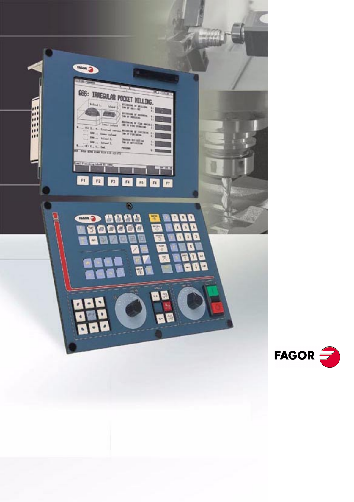
Page 1
8040 CNC
N
EW
EATURES
F
REF. 0307
OFT
(S
(S
T: 8.XX)
OFT
T: 8.1X)
Page 2

8040 CNC
NEW F
EATURES
(S
T: 8.XX)
OFT
T: 8.1X)
(S
OFT
Page 2 of 2
Page 3

NDEX
I
Version 8.01
1 Detected errors ..................................................................................................................1
2 The meaningless zeros will not be displayed .....................................................................2
3 Management of the new Sercos board ..............................................................................2
4 Key inhibiting codes for the monitors .................................................................................2
5 New work languages ..........................................................................................................2
6 Load version without using an external microprocessor. ...................................................2
7 WINDNC improvements .....................................................................................................3
8 Telediagnosis .....................................................................................................................4
9 Improvements to the profile editor ......................................................................................5
10 Modified variables ..............................................................................................................5
11 New variables .....................................................................................................................6
12 New range of OEM subroutines. ........................................................................................8
13 RPT instruction with program number definition ................................................................8
14 Improved non-random tool magazine management ..........................................................9
15 Improved drive parameter management ............................................................................9
16 User and OEM arithmetic parameters ................................................................................9
17 Exponential type of leadscrew backlash peak .................................................................10
18 Functions associated to machine safety ..........................................................................11
18.1 Limit the feedrate of the axes and the spindle speed ................................................11
18.2 Cycle Start disabled by hardware errors ...................................................................11
18.3 Maximum spindle machining speed. .........................................................................11
19 Axes (2) controlled by a drive ...........................................................................................13
20 Mandatory home search ..................................................................................................13
21 Change of active tool from the PLC .................................................................................13
22 Synchronize a PLC axis with a CNC axis ........................................................................14
23 Minimum step "L" in cycles G83, G60 and G61 ...............................................................15
24 Threads with different entries ...........................................................................................15
25 Error register ....................................................................................................................15
26 Proportional and Derivative Gain with the "C" axis ..........................................................15
27 Path JOG mode ...............................................................................................................16
28 Tool inspection .................................................................................................................17
29 New instructions in the configuration language ................................................................18
30 Oscilloscope function .......................................................................................................18
30.1 Configuration .............................................................................................................20
30.2 Scale / Offsets ...........................................................................................................24
30.3 Analysis .....................................................................................................................25
30.4 Parameters ................................................................................................................25
30.5 Actions .......................................................................................................................26
30.6 Begin .........................................................................................................................26
31 TC model. Execute a part-program ..................................................................................27
32 TC model. Maintain F, S y Smax on power up .................................................................27
33 TC model. Messages and warnings .................................................................................27
34 TC model. Tool calibration ...............................................................................................27
35 TC model. Modifications in the turning cycle ....................................................................28
36 TC model. Modifications in the facing cycle .....................................................................29
37 TC model. Modifications in the taper turning cycle ..........................................................29
38 TC model. Modifications in the tapping cycle ...................................................................30
39 TC model. Modifications to the grooving cycle .................................................................35
40 TC model. Modifications in the profile cycle .....................................................................36
41 TC model. Cycle selection ...............................................................................................36
NEW F
8040 CNC
EATURES
Page i of ii
Page 4

8040 CNC
Version 8.11
1 Detected errors ................................................................................................................39
2 New validation codes .......................................................................................................41
3 Smooth stop in probing move (G75/G76) ........................................................................41
4 Square-corner or round-corner machining when changing tool offset .............................41
5 New management of the distance-coded reference mark (I0) .........................................42
6 Improved look ahead ........................................................................................................42
7 Leadscrew error compensation in both directions ............................................................42
8 Parameters accessible from the oscilloscope or OEM subroutine ...................................43
8.1 Axis parameters that may be modified from the oscilloscope ...................................43
8.2 General parameters modifiable from the oscilloscope ..............................................43
8.3 Machine parameters modifiable from an OEM program ...........................................43
9 Sampling period ...............................................................................................................44
10 Thread exit going through the end point ..........................................................................44
NEW F
EATURES
Page ii of ii
Page 5
ERSION
V
8.01
1 Detected errors
NBTOOL Variable
The installation and programming manuals indicate that this variable
is read-only from the CNC, PLC and DNC.
Actually, it is read-only from the CNC and DNC and it can only be
used inside a tool-change subroutine.
OPMODE Variable
This variable also returns the following code:
8040 CNC
25 Rapid simulation with S=0
56 User parameter table
57 OEM parameter table
117 Oscilloscope.
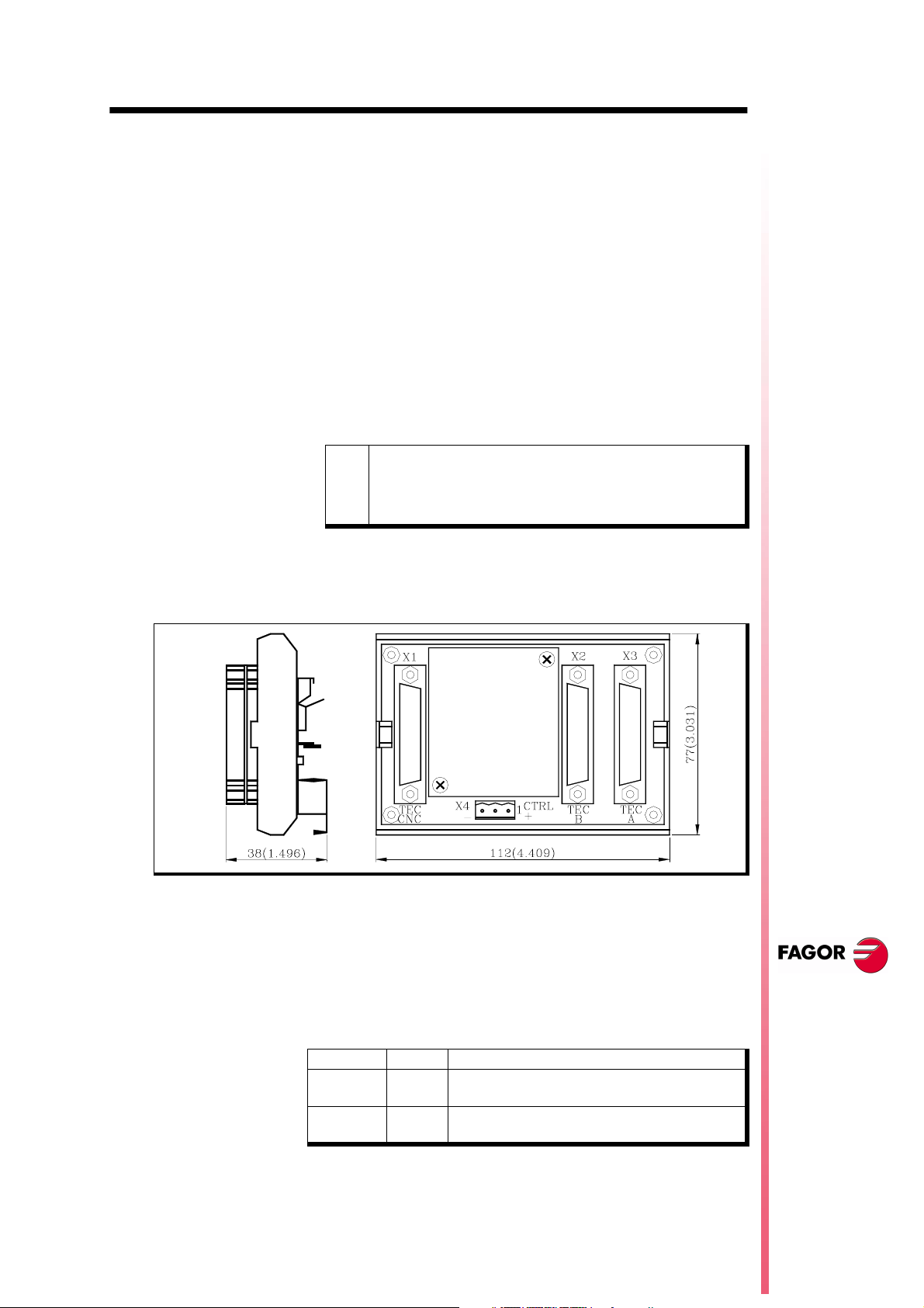
Connection of the KS50/55 adapter:
The installation manual describes how to use this adapter, but the
correct connection is the following:
25-pin female SUB-D type (normal density) connector to connect
X1
the "Central Unit + Monitor".
25-pin female SUB-D type (normal density) connector to connect
X2
the "Alphanumeric keyboard + Monitor".
25-pin female SUB-D type (normal density) connector to connect
X3
the "Operator panel".
3-pin male Phoenix connector, 7,62 mm pitch, to select the
X4
keyboard to be attended by the Central Unit.
Pin Value Meaning
10V
2
3
If connector X4 is not supplied with voltage, the CNC attends to
the operator panel.
24V
----
GND
The CNC attends to the operator panel
The CNC attends to the alphanumeric keyboard
Not being used
External power supply
NEW F
EATURES
(S
T: 8.XX)
OFT
Detected errors
Page 1 of 46
Page 6
8040 CNC
2 The meaningless zeros will not be displayed
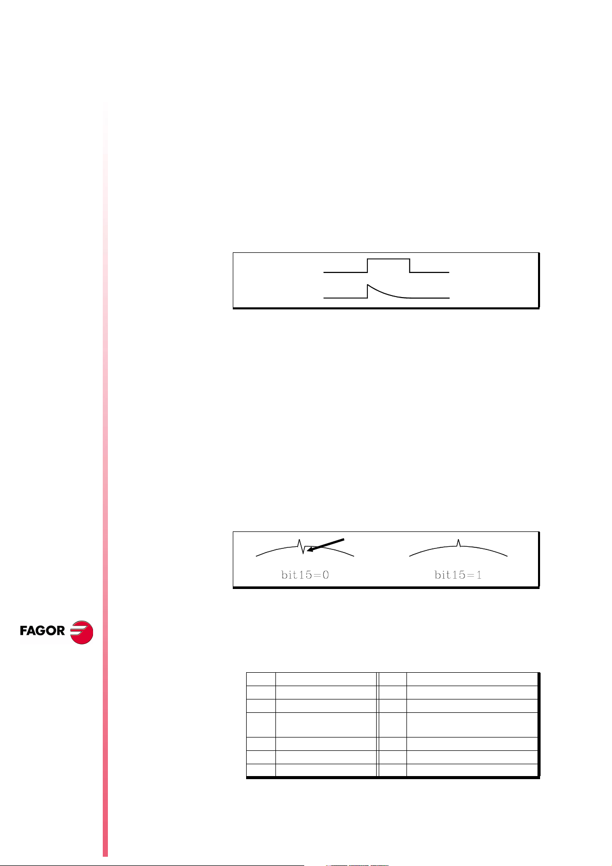
From this version on, the data displayed on the screen (positions,
feedrates, etc.) will not display the meaningless zeros to the left of
the value. Example:
From this version on Z -4.210
Previous versions Z -00004.210
3 Management of the new Sercos board
This software version is ready to work with the new Sercos boards,
reference: 902103 and newer.
The "Hardware diagnosis" function shows these boards as
"SERCOS816" because they carry the SERCON 816 chip.
4 Key inhibiting codes for the monitors
The inhibiting codes for softkeys F1 through F7 of monitors models
such as “NMON-55-11-LCD” are:
F1 F2 F3 F4 F5 F6 F7
Bit 24
R508
Bit 25
R508
Bit 26
R508
Bit 27
R508
Bit 28
R508
Bit 29
R508
Bit 30
R508
N
EW FEATURES
(S
T: 8.XX)
OFT
5 New work languages
Basque and Russian are now available from this version on.
LANGUAGE (P122)
Defines the work language
Possible values:
0 English 1 Spanish 2 French
3 Italian 4 German 5 Dutch
6Portuguese 7Czech 8Polish
9 Mainland Chinese 10 Basque 11
Russian
By default 0
6 Load version without using an external microprocessor.
This feature is available on 8040 CNC models whose identifying
label shows "03 A" or later and whose software version is V08.01 or
later.
It is not necessary to turn the CNC off and back on or actuate the
external switch to update the software version, as indicated in
section 2.2 of the Operating Manual.
To update the CNC software, proceed as follows:
The meaningless
zeros will not be
displayed
Page 2 of 46
Remove the "Memkey Card" and insert the "Memory Card" that
•
contains the software version to be updated.
Access the Diagnosis mode - Software Configuration and press
•
the [Load version] softkey.
The CNC will show the software updating stages and their status.
Page 7
When done updating it, remove the "Memory Card" that contains
•
the software version and insert the "Memkey Card" back.
Note:
• If the "[load version]" softkey is pressed but the Memory
Card containing the software version is missing, the CNC
will issue the relevant error message.
• The CNC cannot execute anything if it has the Memory
Card that contains the software version.
7 WINDNC improvements
From this CNC version on and having WINDNC version V2.0 and the
following, it is possible:
Select the work unit for CNC files Option (a).
•
(b)
(c)
(a)
(d)
Then indicate the desired work unit: Memory (b), Hard Disk (c) or
Card A (d).
From a PC, using the WINDNC application, copy from the CNC
•
to the PC or vice versa, any file, program or table available in the
CARDA or hard disk. The available new tables are:
OEP OEM arithmetic parameters
USP USER arithmetic parameters
DRS Spindle drive table
DS2 Table of the Second Spindle drive
DPX Table for the Auxiliary spindle drive
DRX, DRY,
DRZ, DRU,
DRV, DRW,
DRA, DRB,
DRC
8040 CNC
Tables for axis drives
These tables are compatible with the tables that have been
saved from the drive to a PC via serial line using WINDDS.
Consult the table directory (machine parameters, zero offsets,
•
magazine, tools, tool offsets, geometry, user parameter, OEM
parameter, etc.).
Read global and local arithmetic parameters individually using
•
variables GUPn and LUP(a,b).
The installation and programming manuals describe how to use
these variables.
Having telediagnosis, display CNC screens at the PC in remote
•
mode via serial line or via MODEM.
Having telediagnosis, dial the telephone number associated with
•
the modem at the PC.
NEW F
EATURES
(S
T: 8.XX)
OFT
WINDNC
improvements
Page 3 of 46
Page 8
8040 CNC
(
)
Línea telefónica
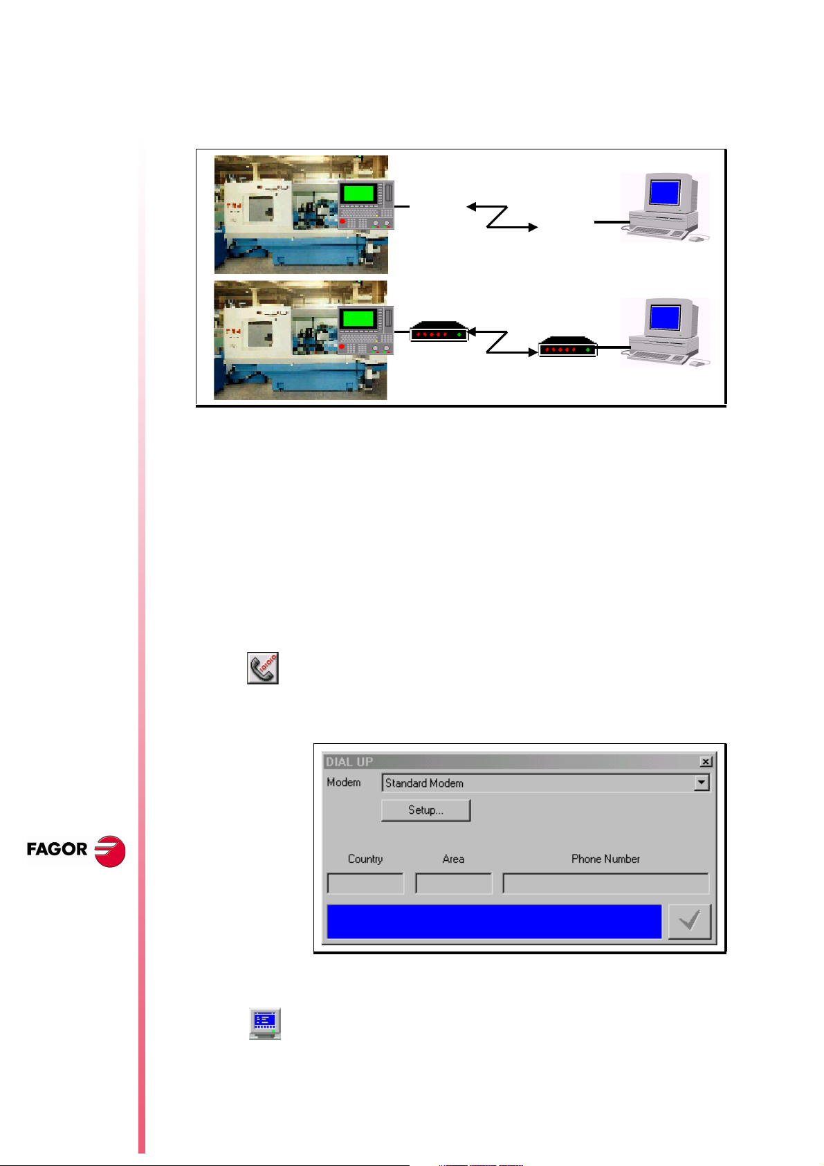
8 Telediagnosis
It may be used to govern and monitor the CNC status remotely
through the RS232 serial line or using a modem through a telephone
line.
CNC PC
(RS232)
RS232
CNC PC
The remote PC must have the WINDNC application version 2.00 or
later installed in it and the CNC software version must be V08.01 or
later.
CNC connection to the telephone line
It must be done through the RS232 serial line and using a modem
that has RS232 serial line communication.
First, turn on the modem, then the CNC and then the remote PC, in
that order.
PC connection to the telephone line
Connect the PC to the telephone line through a modem and execute
the WINDNC application. Within the options for the serial line, select
(a)
option (a).
Módem
Módem
Telephone line
Internet - RDSI
N
EW FEATURES
(S
T: 8.XX)
OFT
Telediagnosis
Page 4 of 46
The application shows the following window. Indicate which modem
is being used and the telephone number to dial.
PC-CNC communication (Telediagnosis)
Once the connection has been established (either via serial line or
via modem), select the "telediagnosis" option (b) of the WINDNC
(b)
application.
From this moment on, the CNC may be governed either from its own
keyboard or remotely from the PC keyboard.
Page 9
The PC will display the same information (screens) as the CNC.
•
It is possible to access the different CNC modes, modify tables
•
and parameters when knowing the password, simulate
programs, etc.
For safety reasons, it is not possible to move the axes of the
•
machine or execute part-programs.
With the WINDNC application, it is also possible to send to the CNC
a file containing a keystroke sequence, option (c).
(c)
While in remote control mode, no other DNC command may be
executed through the same serial line (for example the execution of
an infinite program).
With option (d), it is possible to save into a BMP file a CNC screen
image that is being displayed.
(d)
End the communication (End telediagnosis)
To end the communication, select option (e) from those associated
to the serial line in the WINDNC application.
(e)
9 Improvements to the profile editor
8040 CNC
The following improvements have been made:
It is possible to select the coordinate system of the work plane, axes
and their direction.
The right window, under "Display Area", indicates whether the
autozoom is on or not and the selected coordinate system.
It includes graphic data editing. Use the up-arrow and down-arrow
keys to select the desired window and key in the desired value.
It is possible to modify rectangular and circular elements.
There are 2 new softkeys:
Save and continue
To save a profile without having to quit the session.
Undo
To undo the last modification.
On conversational models, TC and TCO, it indicates the number of
the profile being edited.
10 Modified variables
HARCON
It indicates, with bits, the CNC's hardware configuration.
The bit will be "1" when the relevant configuration is available.
From now on, bits 24, 25, 26 indicate the type of monitor and bits 27,
28 the CPU turbo board being used.
bit
26,25,24 000
001
28,27 00
01
Color LCD Monitor
Monochrome LCD monitor
Turbo board at 25 Mhz
Turbo board at 40 Mhz
NEW F
EATURES
(S
T: 8.XX)
OFT
Improvements to
the profile editor
Page 5 of 46
Page 10

8040 CNC
MPGn
MP(X-C)n
MPSn
MPSSn
MPASn
These variables, related to machine parameters, that until now were
read-only, from this version on, can be read and written from the
CNC in the following cases:
•
•
MPLCn
To modify machine parameters from the PLC, an OEM subroutine
containing the relevant variables must be executed using the
CNCEX instruction.
In order for the CNC to assume the new values, one must operate
according to the indicators associated with each machine
parameter.
11 New variables
Feedrate related variables
When they are executed inside an OEM program.
When they are executed inside an OEM subroutine.
// It is necessary to press the keystroke sequence: "Shift -
Reset" or turn the CNC off and back on.
/ Just press Reset.
The rest of the parameters (those unmarked) will be updated
automatically, only by changing them.
N
EW FEATURES
FREAL(X-C)
FTEO(X-C)
Actual (real) X-C axis feedrate Is read-only from the CNC, DNC and
PLC.
Theoretical X-C axis feedrate Is read-only from the CNC, DNC and
PLC.
Coordinate related variables
DPLY(X-C)
DRPO(X-C)
GPOS(X-C)n p
"Coordinates of the selected axis" displayed on the screen Is readonly from the CNC, DNC and PLC.
Position indicated by the X-C axis Sercos drive (Sercos variable
PV51 or PV53 of the drive). Is read-only from the CNC, DNC and
PLC.
Programmed coordinate for a particular axis (X-C), in the indicated
block (n) and program (p).
(P100 = GPOSX N99 P100)
It assigns to P100 the value of the coordinated programmed for
the X axis in label N99 and located in program P100.
It Is read-only and it is only enabled at the CNC. Only programs
located in RAM memory may be consulted.
(S
T: 8.XX)
OFT
New variables
Page 6 of 46
If the defined program number does not exist, it issues Error 69
•
"Program does not exist".
If the defined block number does not exist, it issues error 1060
•
"undefined label".
If the requested axis is not programmed in the indicated block, it
•
returns the value: 100000.0000
Page 11

Spindle related variables
DRPOS
SDRPOS
FTEOS
SFTEOS
Position indicated by the Sercos drive of the spindle. Is read-only
from the CNC, DNC and PLC.
Position indicated by the Sercos drive of the second spindle. Is readonly from the CNC, DNC and PLC.
Theoretical spindle turning speed. Is read-only from the CNC, DNC
and PLC.
Theoretical second spindle turning speed. Is read-only from the
CNC, DNC and PLC.
Speed limit related variables
MDISL
Maximum spindle machining speed. It is read-write from the PLC
and read-only from DNC and CNC.
This variable is also updated with the programmed S value, in the
following cases:
When programming "G92 S" in MDI mode
When programming "G92 S" in ISO code in MC mode.
8040 CNC
Variables related to Probe cycles
TIPPRB
It indicates the PROBE cycle being executed at the CNC. Is readonly from the CNC, DNC and PLC.
PLC related variables
PLCMM(n)
It permits reading modifying a single PLC mark (the PLCM variable
permits reading or modifying 32 marks at once). It is read-write and
it is only available from the CNC.
(PLCMM4 = 1)
It sets mark M4 to "1" and leaves the rest untouched
(PLCM4 = 1)
It sets mark M4 to "1" and the following 31 marks (M5, through
M35) to "0"
Feedback related variables
ASIN(X-C)
"A" signal of the CNC sinusoidal feedback for the X-C axis. Is readonly from the CNC, DNC and PLC.
NEW F
EATURES
BSIN(X-C)
ASINS
BSINS
"B" signal of the CNC sinusoidal feedback for the X-C axis. Is readonly from the CNC, DNC and PLC.
"A" signal of the CNC sinusoidal feedback for the spindle. Is readonly from the CNC, DNC and PLC.
"B" signal of the CNC sinusoidal feedback for the spindle. Is readonly from the CNC, DNC and PLC.
(S
T: 8.XX)
OFT
New variables
Page 7 of 46
Page 12
SASINS
"A" signal of the CNC sinusoidal feedback for the second spindle. Is
read-only from the CNC, DNC and PLC.
8040 CNC
SBSINS
"B" signal of the CNC sinusoidal feedback for the second spindle. Is
read-only from the CNC, DNC and PLC.
Variables related to the WGDRAW application
PANEDI
DATEDI
Number of the screen created by the user or by the OEM using the
WGDRAW application for diagnosis, consultation, work cycle, etc,
that is being consulted. Is read-only from the CNC, DNC and PLC.
Number of the screen element created using the WGDRAW
application that is being consulted. Is read-only from the CNC, DNC
and PLC.
12 New range of OEM subroutines.
A new range of OEM subroutines has now been defined.
Available subroutine ranges:
General subroutines SUB 0001 - SUB 9999
OEM subroutines SUB 10000 - SUB 20000
Although OEM subroutines are treated like the general ones, the
have the following restrictions:
N
EW FEATURES
(S
T: 8.XX)
OFT
They can only be defined in OEM programs, having the [O]
•
attribute. Otherwise, it shows error 63 "Program subroutine
number between 1 and 9999.".
If the subroutine to be executed using CALL, PCALL or MCALL
•
is an OEM subroutine and it is located in a program that does not
the [O] attribute, it will issue Error 1255 "Subroutine restricted to
OEM program".
13 RPT instruction with program number definition
From this version on, the RPT instruction can execute a portion of
the same program or of the indicated program.
(RPT N(expression), N(expression), P(expression))
The new parameter "P" indicates the number of the program located
in RAM memory containing the two blocks defined by the N labels.
If parameter "P" is not defined, the CNC interprets that the portion
•
to be repeated is located in the same program.
If the defined program number does not exist, it issues Error 69
•
"Program does not exist".
New range of OEM
subroutines.
Page 8 of 46
Page 13
Warning:
Since the RPT instruction does not interrupt block preparation or tool
i
compensation, it may be used when using the EXEC instruction and
while needing to maintain tool compensation active.
14 Improved non-random tool magazine management
When the tool changer is configured as non-random, the tools must
be placed in the tool magazine table in the pre-established order (P1
T1, P2 T2, P3 T3, P4 T4, etc.).
With this improvement, it is possible to assign several tools to each
tool position.
8040 CNC
TOOLMATY (P164)
This g.m.p. is taken into account when using a non-random tool
magazine. It indicates how many tools may be assigned to each
turret position.
0 One tool per position
1 Several tools per position.
15 Improved drive parameter management
From this version on, it also possible to save and load into a
peripheral device or PC the drive parameter tables via Sercos serial
line.
For that, select the parameter page of the desired drive at the CNC
and press the relevant softkey.
A file saved from the CNC via WINDNC may be loaded into the drive
via DDSSETUP and vice versa.
16 User and OEM arithmetic parameters
There are now two new ranges of global arithmetic parameters.
User parameters Range: P1000 - P1255.
OEM parameters Range: P2000 - P2255
By default 0
For compatibility with previous versions, global arithmetic
parameters P100-P299 are maintained and may be used by the
user, by the OEM and by the CNC cycles.
There are now 2 new tables of global arithmetic parameters.
Arithmetic parameter tables available:
GUP Global parameters P100-P299
USP User parameters P1000-P1255
OEP OEM parameters P2000 - P2255
Changing an OEM parameter requires an OEM password.
OEM parameters and subroutines having OEM parameters may
only be written in OEM programs having the [O] attribute.
NEW F
EATURES
(S
T: 8.XX)
OFT
Improved non-
random tool
magazine
management
Page 9 of 46
Page 14
8040 CNC
On the TC and TCO models, when using OEM parameters in the
configuration programs, these programs must have the [O] attribute.
If they don't, an error will be issued when editing a user cycle that
refers to OEM parameters in write mode.
General machine parameters “ROPARMIN” and “ROPARMAX” may
be used to protect any global parameter (user and OEM included)
against being written.
There is no restriction to read these parameters.
17 Exponential type of leadscrew backlash peak
The additional command pulse used to make up for the possible
leadscrew backlash in movement reversals may be rectangular or
exponential.
If the duration of the rectangular pulse is adjusted for low speed, it
could be excessive for high speed or insufficient for low speed when
adjusted for high speed.
N
EW FEATURES
(S
T: 8.XX)
OFT
Exponential type of
leadscrew
backlash peak
ACTBAKAN (P144)
In this cases, it is recommended to use the exponential type that
applies a strong pulse at the beginning and decreases in time.
Bit 16 of g.m.p. “ACTBAKAN (P144)” indicates the backlash peak
being used.
0 rectangular leadscrew backlash peak
1 exponential type of leadscrew backlash peak
By default 0
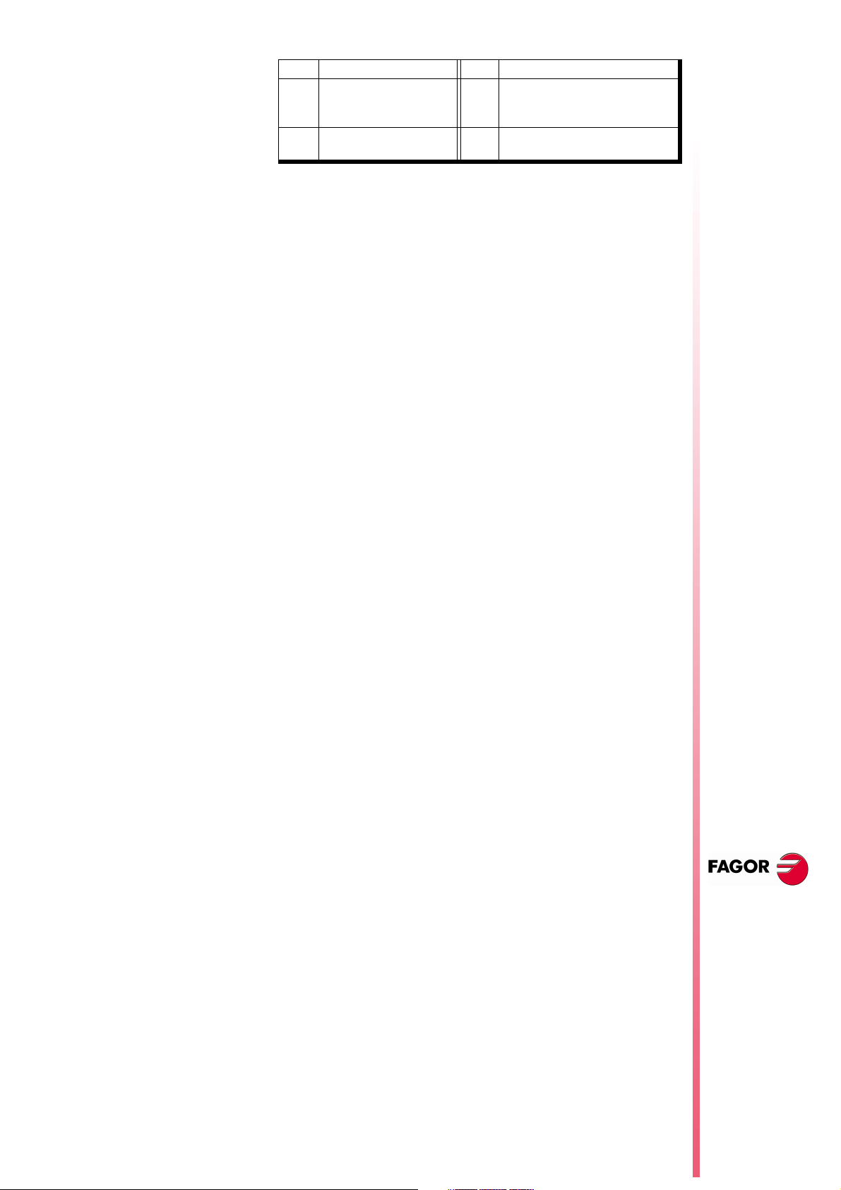
A finer tuning of the leadscrew backlash consists in testing the circle
geometry and watch for internal peaks when changing quadrants
(left figure). In these cases, it is recommended to set bit 15 of g.m.p.
“ACTBAKAN (P144)” to "1" to eliminate the internal peaks.
Under these conditions, the CNC eliminates the leadscrew backlash
peak as soon as it detects a movement reversal. If the internal peaks
are not eliminated, adjust the leadscrew backlash compensation
better.
It has 16 bits counted from left to right.
bit Function bit Function
19
210
Additional pulse with G2
3
412
513
614
/ G3
11
Page 10 of 46
Page 15
bit Function bit Function
It minimizes internal peaks
715
816
detected with the circle
geometry test
Exponential leadscrew
backlash peak
By default, all bits are set to "0".
18 Functions associated to machine safety
18.1 Limit the feedrate of the axes and the spindle speed
It is possible to limit the feedrate of the axes and the spindle turning
speed.
8040 CNC
FLIMIT (P75)
SLIMIT (P66)
The a.m.p. "FLIMIT" sets the maximum feedrate for each axis and
the s.m.p. "SLIMIT" sets the maximum turning speed for each
spindle.
FLIMITAC (M5058)
When the PLC sets this signal high, it limits the feedrate of all the
axes. It does not let any feedrate to exceed the value set by the
corresponding a.m.p. "FLIMIT (P75)" .
SLIMITAC (M5059)
When the PLC sets this signal high, it limits the speed of all the
spindles. It does not let any feedrate to exceed the value set by the
corresponding s.m.p. "SLIMIT (P66)" .
The limitation is applied in all work modes, including the PLC
channel. When the mark is high, the CNC applies the limitation and
when going low, it restores the programmed F or S.
When the spindle moves with PLCCNTL, the spindle limitation is
ignored.
18.2 Cycle Start disabled by hardware errors
If when pressing the Cycle-Start key, a hardware error is detected
(Sercos board error, CAN board error, etc.), the CNC issues the
corresponding error message and does not allow executing or
simulating the program.
18.3 Maximum spindle machining speed.
The following safety regulation requires limiting the spindle speed on
lathes:
"A program will not be executed in machining mode unless the maximum
spindle speed value for the part is entered as well as the proper
maximum speed for the part holding fixture for the machine.
If the operator does not enter or validate these speeds every time the
program is changed, it will not be possible to execute the program
machining mode.
The speed cannot exceed the lower speed among the maximum set by
parameter, the maximum set by program and the maximum entered by
hand
A new variable (MDISL) associated with speed limits is now
available to make this safety maneuver easier. It is read-write from
the PLC and read-only from DNC and CNC.
NEW F
EATURES
(S
T: 8.XX)
OFT
Functions
associated to
machine safety
Page 11 of 46
Page 16

8040 CNC
This variable is also updated with the programmed S value, in the
following cases:
When programming "G92 S" in MDI mode
•
When programming "G92 S" in ISO code in TC mode.
•
In TC mode, when a new speed limit is defined in the "SMAX"
•
field.
The speed limits entered via CNC, PLC (PLCSL) and DNC (DNCSL)
keep the same functionality and priority unaffected by the new
MDISL variable; in other words, the CNC keeps limiting the spindle
speed like until now.
In order to comply with the safety regulation, it is recommended to
manage from the PLC the variables associated with speed limits as
shown in the following example:
A new part-program cannot be executed without previously
•
entering the speed limit. Otherwise, a message will be displayed.
If the program is executed again, the limit does not have to be
entered again, it is only required when executing the program for
the first time.
While executing a program if a new limit is entered in MDI, the
•
new one will replace the previous one.
In independent TC cycles it is not required to enter the SMAX
•
because it is already defined in each cycle.
N
EW FEATURES
(S
T: 8.XX)
OFT
Functions
associated to
machine safety
Page 12 of 46
If the program being executed already has a G92S, it will be
•
validated only if it is smaller than the one programmed in MDI.
When having two main spindles, the speed limit entered will be
•
valid for both.
PRG
REA
()=CNCRD(OPMODA,R100,M1000) ; Reading of OPMODA
B0R100 AND INCYCLE = M100 ; Indicator of program in execution
;
DFU M100 ; At the beginning of the execution
= CNCRD(PRGN,R101,M1000) ; reads the program in execution
= CNCRD(MDISL,R102,M1000) ; and the S limitation from MDI
;
M100 ; During the execution
= CNCRD(PRGSL,R103,M1000) ; and the S limitation from CNC
;
M100 AND CPS R101 NE R201 ; If new program in execution
= M101 ; activates mark M101
;
M100 AND CPS R101 EQ R201 ; If same program in execution
= M102 ; activates mark M102
;
M101 ; If new program in execution
AND CPS R102 EQ 0 ; and the "S" has not been limited from MDI
= ERR10 ; Error 10: "The S has not been limited from
MDI"
;
M101 ; If new program in execution
AND CPS R102 NE 0 ; and the "S" has been limited from MDI
= MOV R101 R201 ; it copies the number of the program in
execution
= MOV R102 R202 ; and the S limitation from MDI
;
M102 ; If same program in execution
AND CPS R102 NE 0 ; and the "S" is limited again from MDI
= MOV R102 R202 ; it copies the S limitation from MDI
;
M100 ; If program in execution
Page 17
AND CPS R202 LT R103 ; and "S" limitation from MDI < "S" limitation
= CNCWR(R202,PLCSL,M1000) ; Applies "S" limitation from the PLC with the
;
M100 ; If program in execution
AND CPS R202 GT R103 ; and "S" limitation from MDI > "S" limitation
= CNCWR(R210,PLCSL,M1000) ; It does not limit "S" from PLC (R210=0)
;
DFD M100 ; At the end of execution
= CNCWR(R210,PLCSL,M1000) ; it cancels "S" limitation from the PLC
= CNCWR(R210,MDISL,M1000) ; and it resets the MDISL variable
;
END
19 Axes (2) controlled by a drive
Until this version, when having 2 axes controlled by a single drive,
the polarity of the analog output (command sign) always
corresponded to that of the main axis.
From this version on, since sometimes the turning direction of the
two axes may be different, the sign of the command for each axis will
taken into account [the one set by a.m.p “LOOPCHG (P26)”].
Warning
from CNC
value set in MDI
from CNC
8040 CNC
This new version is not compatible with previous versions.
On machines having axes controlled by a single drive the secondary
axis might run away.
Before installing the new software, make sure that the a.m.p.
"LOOPCHG (P26)" of the associated axis has the same value as that of
the main axis.
20 Mandatory home search
The CNC forces a home search on an axis by setting the relevant
REFPOIN* mark low in the following cases:
On CNC power-up
•
After executing SHIFT RESET
•
When the feedback is direct through the axes board and a
•
feedback alarm occurs.
When losing feedback count via Sercos due to broken
•
communication. Difference greater than 10 microns (0.00039")
or 0.01º
When changing machine parameters that affect the memory
•
distribution, for example: number of axes.
In all these cases, a home search must be carried out so the signal
is set back high.
NEW F
(S
OFT
EATURES
T: 8.XX)
21 Change of active tool from the PLC
If the tool change process is interrupted, the values of the tool
magazine table and active tool may not reflect the machine's reality.
To update the tool table, variables TOOL, NXTOOL, TOD and
NXTOD that until now were read-only are now read-write from the
Axes (2) controlled
by a drive
Page 13 of 46
Page 18
8040 CNC
PLC as long as a block or a part-program is not being executed or
simulated.
TOOL Number of the active tool
NXTOOL Number of the next tool that is selected, but waiting for the
execution of an M06 to become active.
TOD Number of the active tool offset
NXTOD Number of the offset of the next tool that is selected, but
waiting for the execution of an M06 to become active.
This way, it is possible to resume the tool change from the PLC and
redefine the tool table according to their positions using the TMZT
variable.
To allocate a magazine position to the tool that is considered active
by the CNC and is physically in the tool magazine, proceed as
follows:
Cancel the tool, TOOL=0 and TOD=0
1.
Assign the relevant position using the TMZT variable.
2.
When trying to write in variables TOOL, NXTOOL, TOD and NXTOD
check the OPMODA variable to make sure that no block or partprogram is being executed or simulated. The following bits must be
at "0".
OPMODA
bit 0 Program in execution
bit 1 Program in simulation
bit 2 Block in execution via MDI, JOG
bit 8 Block in execution via CNCEX1
N
EW FEATURES
(S
T: 8.XX)
OFT
Synchronize a PLC
axis with a CNC
axis
22 Synchronize a PLC axis with a CNC axis
To synchronize an axis of the PLC channel with another one of the
CNC channel (main channel), set a.m.p. SYNCHRO (P3) of the PLC
axis indicating which axis it must synchronize with.
Axis synchronization is carried out from the PLC by activating the
general input "SYNCHRO" of the axis to be coupled as slave (PLC
axis).
To assure that both axes are stopped when they are being
synchronized, we suggest:
To execute a special M function at the CNC so the PLC executes
•
another M function in the PLC channel and activates the general
input "SYNCHRO".
The M function of the main channel must not end until the PLC's
•
M function execution is completed and the ENABLE signal of the
slave axis is set high.
Once both axes are synchronized, it won't be possible to program
movements of the PLC axis. Otherwise, error 1099 will be issued:
"Do not program a slaved axis".
During synchronization, it does not check whether the PLC axis gets
in position or not. For this reason:
The logic output "ENABLE" of the PLC axis is activated (allowing
•
motion).
Page 14 of 46
The logic output "INPOS" of the PLC axis is deactivated (the axis
•
is NOT in position).
Page 19

General input "INHIBIT" of the PLC axis is ignored, thus not being
•
possible to prevent it from moving.
The execution of the movement of the synchronized slave axis
•
cannot be aborted even by activating the general input
"PLCABORT".
If an error occurs canceling the "ENABLE" logic outputs of all the
axes, it also cancels the synchronization.
To end synchronization, cancel the "SYNCHRO" general input of the
PLC axis.
To assure that the PLC axis recovers its position after the
synchronization, it is recommended to use other 2 special M
functions, one at the CNC and another one at the PLC.
23 Minimum step "L" in cycles G83, G60 and G61
A new "L" parameter has been added to the drilling cycles G83, G60
and G61.
G83 X Z I B D K H C L R
G60 X Z I B Q A J D K H C S L R
G61 X Z I B Q A J D K H C S L R
It is an optional parameter used with "R" values other than "1". It
indicates the minimum value allowed for the drilling peck. If not
programmed, a value of 0 mm is assumed.
8040 CNC
24 Threads with different entries
Available when setting s.m.p. “M19TYPE (P43)=1”
A new "V" parameter has been added to the tapping cycles G86 and
G87.
G86-G87: X Z Q R I B D L C J A V
It is an optional parameter that indicates the number of thread
entries to make. If not programmed or programmed with a value of
"0", it means that the thread has only one entry.
25 Error register
The "CNC" screen of the "STATUS" mode offers the softkey: [BB].
Pressing this softkey displays the error history indicating the error
number and when it occurred.
This information is very useful to the service technician. Pressing the
[SAVE] softkey requests the number of the CNC program to store
that information.
If the service department asks you for that program, transfer it to a
PC via DNC and send it to the corresponding address via internet.
26 Proportional and Derivative Gain with the "C" axis
NEW F
EATURES
(S
T: 8.XX)
OFT
Minimum step "L"
in cycles G83, G60
and G61
For smoother machining, the proportional and derivative gains are
canceled automatically when machining in the XC and ZC planes.
Page 15 of 46
Page 20
8040 CNC
CAXGAIN (P163)
This g.m.p. lets the OEM decide whether these gains are to be
canceled or not.
With “CAXGAIN (P163) =1” and high values of FFGAIN and
DERGAIN the machine could be jerky depending on the type of part
being machined. In these cases, we suggest to select a gain range
whose FFGAIN AND DERGAIN values small or zero.
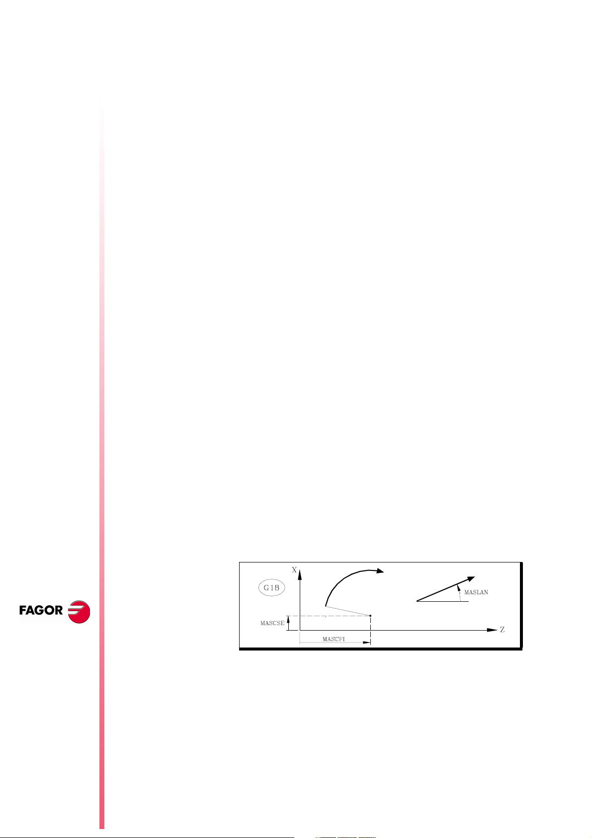
27 Path JOG mode
It is similar to the "Path Handwheel" mode.
The "Path Handwheel" mode acts at the Handwheel position of the
selector switch whereas the "Path JOG" acts at the continuous and
incremental jog positions of the selector switch.
"Path JOG" may be used to act upon the jog keys of an axis to move
both axes of the plane at the same time for chamfering (straight
sections) and rounding (curved sections).
The CNC assumes as "Path JOG" the keys associated with the Z
axis.
0 They are canceled
1 They are not canceled
Default value
N
EW FEATURES
This feature must be managed from the PLC.
To turn on or off the "Path JOG" work mode, use CNC logic input
“MASTRHND” M5054,
M5054 = 0 "Path JOG" function off.
M5054 = 1 "Path JOG" function on.
To indicate the type of movement, use CNC logic input
“HNLINARC” M5053
M5053 = 0 Linear Path
M5053 = 1 Circular path.
For a linear path, indicate the path angle in the MASLAN variable
(value in degrees between the linear path and the first axis of the
plane)
For an arc, indicate the arc center coordinates in the MASCFI,
MASCSE variables (for the first and second axes of the main
plane)
(S
T: 8.XX)
OFT
Path JOG mode
Page 16 of 46
Variables MASLAN, MASCFI and MASCSE may be read and
written from the CNC, DNC and PLC.
Page 21
Operation
Considerations
When pressing one of the associated keys, Z+ and Z-, the CNC acts
as follows:
Selector
Switch
Position
Continuous
Incremental
Handwheel It ignores the keys.
Path JOG Type of movement
OFF
ON
OFF
ON
Only the axis and in the indicated
direction
Both axes in the indicated direction along
the indicated path
Only the axis, the selected distance and
in the indicated direction
Both axes, the indicated distance and
direction, but along the indicated path
The rest of the keys always operate the same way regardless of
whether the "Path JOG" function is on or off. It only moves the
selected axis and in the indicated direction.
It assumes as axis feedrate the one selected in JOG mode and it is
affected by the override. If F0 is selected, it assumes the one
indicated by a.m.p. “JOGFEED (P43)”. The [Rapid] key is ignored.
8040 CNC
The movements in "Path JOG" observe the travel limits and zone
boundaries
The movements in "Path JOG" may be aborted:
•
•
•
•
28 Tool inspection
The tool inspection mode now offers a new option: "Modify Offsets".
This window shows (at the top) a help graphic and the tool fields that
can be edited.
When editing the active tool, it is possible:
When NOT editing the active tool, it is possible:
By pressing the [CYCLE STOP] key
By selecting one of the handwheel positions of the JOG selector
switch.
By setting the general logic input “MASTRHND (M5054)” =0.
Setting the general logic input “\STOP (M5001)”=0.
To modify the I and K data.
Select another tool for calibration (T xx Enter).
To modify the I, K and D data.
Select another tool for calibration (T xx Enter).
NEW F
(S
OFT
EATURES
T: 8.XX)
The I and K values
The values entered in the I, K fields are incremental, they are added
to the ones already in the table. The "I" data is given in diameter.
The new g.m.p. “MAXOFFI (P165)” and “MAXOFFK (P166)” indicate
the maximum value that may be entered in each field. When trying
to enter a greater value, the relevant message will be displayed.
Tool inspection
Page 17 of 46
Page 22
8040 CNC
Warning
To assume the new I and K values, select the tool again.
29 New instructions in the configuration language
The new token "UNMODIFIED" of the configuration language
indicates that the associated element must not take the editing
focus.
;(UNMODIFIED)
It is programmed as a prefix of the instructions
;(W1=GUP100)
It may be used to associate the "W1" data with the value of a
global parameter, variable or resource of the PLC and the
"W1" element is assigned the editing focus.
;(AUTOREFRESH W6=FLWEX)
It refreshes (updates) the value of the graphic element W6
and it assigns the editing focus to it.
The resulting new instructions are:
;(UNMODIFIED W1=GUP170)
It associates the "W" data with the value of a global
parameter, variable or resource of the PLC, but the "W1"
element does not take the editing focus.
;(UNMODIFIED AUTOREFRESH W6=FLWEX)
It refreshes (updates) the value of the graphic element W6 but
it does not take the editing focus.
30 Oscilloscope function
The oscilloscope function is a help tool to adjust the CNC and the
drives.
N
EW FEATURES
(S
T: 8.XX)
OFT
New instructions in
the configuration
language
Page 18 of 46
How to operate
It is possible to represent 4 previously selected variables and
manipulate CNC machine parameters and variables. When using
Fagor Sercos drives, it is also possible to set the parameters of the
drive.
When requesting information (variable or parameter) of a drive that
is not connected via Sercos or when having an old software version,
the message "Variable does not exist" will be displayed.
Changing the machine parameters of the CNC and the drive
requires a password.
To access the Oscilloscope mode, select:
Op Mode - Diagnosis - Adjustements - Scope
Define the variables to be analyzed, the trigger conditions and the
machine parameters of the CNC or the drive to be modified.
Execute a part-program moving the axis or axes to be adjusted.
Page 23

Capture data and then analyze it.
Once data capture has ended, or has been interrupted, it is possible
to analyze the signals and modify the parameters that have been
previously selected, in order to improve the machining conditions.
Capture data, analyze it and modify the parameters again until
achieving the best machining conditions.
8040 CNC
Suggestions
Operation
Execute endless repetitive movements.
After adjusting the axis separately, readjust the interpolating axes
together.
It is up to the user to judge what the best adjustment is, the
oscilloscope function is an assistance tool.
To enter or modify a data on the screens, it must be selected and it
must have the editing focus.
To select another editable data or field, use the [Ï] [Ð]. It is a rotary
selection, if the first element is selected on the screen, when
pressing [Ï] the focus goes to the last one, whereas if the last
element is selected, when pressing [Ð] the focus goes to the first
one.
Not all the data may be edited, only the ones that may be selected,
those having the focus. There are two types of editable fields:
Editable values:
They may be assigned a value, sometimes numerical (numbers
only) and sometimes alphanumerical (numbers and letters).
Before validating the data, it is checked; if the data is incorrect, it
is rejected and a warning message is issued.
Softkeys
Values that may be selected:
The possible values are fixed and one of them may be selected.
Use the [Í] [Î] keys to see the possible values. On this type
values that are icons, the [White/Green] key has the same effect
as the [Î] key.
Accessing the oscilloscope mode enables the following softkeys:
Scale / Offsets
To change the amplitude of each signal, move them vertically
or adjust the time base for all of them.
Analysis
To analyze, using 2 cursors, each signal of the last data
capture.
Parameters
To assign new values to the machine parameters of the CNC
and drive that have been defined in the "Configuration" screen.
Configuration
To define the variables to be analyzed, the trigger conditions
and the machine parameters of the CNC or the drive to be
modified.
Actions
It shows various softkeys to modify the data of each field
(amplitude of the signals, vertical movement, time base
adjustment, position of the cursors, etc.).
NEW F
EATURES
(S
T: 8.XX)
OFT
Oscilloscope
function
Page 19 of 46
Page 24

8040 CNC
Begin
It captures data according to the conditions set on the
"Configuration" screen to be analyzed later on.
30.1 Configuration
To define the variables to be analyzed, the trigger conditions and the
machine parameters of the CNC or the drive to be modified.
It offers 2 screens, one to set the parameters and the other one to
define the variables and trigger conditions.
On the screen for defining variables and the trigger condition, it is
possible to go from block of elements to another using the [page up]
and [page down] keys.
The parameters defining page shows the definition code on the left
column, the parameter name on the center column and the
maximum and minimum values on the right column.
To add a parameter to the list, select the row for the parameter,
enter the definition code indicated later on and press [Enter]. If it
is valid, the rest of the fields are updated and if not, it issues a
warning.
N
EW FEATURES
(S
T: 8.XX)
OFT
Oscilloscope
function
Variable definition
To replace a parameter from the list, select the parameter to be
replaced, enter the definition code of the new parameter and
press [Enter]. If the previous content has been deleted and no
code is entered, the line appears empty.
The [Add a parameter to the list] softkey enters a new empty line
above the currently selected line.
The [Eliminate parameter] softkey eliminates the currently
selected line and shifts all the ones below upwards.
The "Parameter editing" screen shows the parameters in the same
place where they were defined and the empty rows appear blank.
When a parameter is changed on the "Parameter Editing" screen,
the CNC machine parameter table and the drive's work parameters
are updated. The [Save Parameters] softkey is also activated on the
"Configuration - Parameters" screen.
We suggest to access that screen and press the [Save Parameters]
softkey to save the parameter tables that have been changed, those
of the CNC into the CARDA and those of the drive in its FLASH. If
only the CNC parameters have been changed, the drive tables
remain unchanged and vice versa.
Once the values saved are the same as the ones edited last, the
softkey disappears until a new modification is made.
The oscilloscope has 4 graphics channels (CH1, CH2, CH3, CH4).
The following must be defined in each channel:
The code or name of the variable to be shown. See attached
•
tables.
The color used to show them.
•
Whether it will be visible or not.
•
Page 20 of 46
When defining a variable that cannot be captured, an error message
will be issued. If no variable is to be captured in a channel, just leave
Page 25
the name field blank. If all 4 channels are deactivated (without
associated variable) no capture is possible.
The "hidden" channels are not shown graphically (they are not
shown on the screen after the data capture). It is useful when using
this channel to set the trigger condition.
CNC variables that may be assigned to a channel
Variable Characteristics
ANAI(1-8) Voltage of input 1-8
ANAO(1-8) Voltage to apply to output 1-8
FREAL CNC real feedrate
FREAL(X-C) Actual (real) X-C axis feedrate
FTEO(X-C) Theoretical X-C axis feedrate
FLWE(X-C) X-C axis following error
ASIN(X-C) "A" signal of the CNC sinusoidal feedback for the X-C axis
BSIN(X-C) "B" signal of the CNC sinusoidal feedback for the X-C axis
DRPO(X-C) Position indicated by the Sercos drive of the X-C axis
SREAL Real (actual) spindle turning speed.
FTEOS Theoretical spindle turning speed
FLWES Spindle following error
ASINS "A" signal of the CNC sinusoidal feedback for the spindle
BSINS "B" signal of the CNC sinusoidal feedback for the spindle
DRPOS Position indicated by the Sercos drive of the spindle
SSREAL Real (actual) second spindle turning speed.
SFTEOS Theoretical second spindle turning speed
SFLWES Second Spindle following error
SASINS "A" signal of the CNC sinusoidal feedback for the second
spindle
SBSINS "B" signal of the CNC sinusoidal feedback for the second
spindle
SDRPOS Position indicated by the Sercos drive of the second spindle
8040 CNC
Examples: ANAI1, FREAL, FLWEX, FREALZ
Fagor Sercos Drive variables that may be assigned to a channel
Indicate the desired axis and variable, separated by a period.
Examples: X.CV3, Y.SV1, S1.SV2
Variable Characteristics
CV3 CurrentFeedback
SV1 VelocityCommand
SV2 VelocityFeedback
SV7 VelocityCommandFinal
TV1 TorqueCommand
TV4 VelocityIntegralAction
RV1 FeedbackSine
RV2 FeedbackCosine
RV51 Feedback2Sine
RV52 Feedback2Cosine
Trigger conditions
Channel
Trigger
Indicates which variable or channel (CH1, CH2, CH3, CH4) is to be
used as a reference or trigger condition.
Indicates the beginning of the data capture.
NEW F
EATURES
(S
T: 8.XX)
OFT
Oscilloscope
function
If not selected, the data capture begins as soon as the operator
gives the go ahead. The Flank, Level and Position data are ignored.
Page 21 of 46
Page 26

If selected, specify the trigger condition using the Flank, Level and
Position data.
8040 CNC
Flank
Level
Position (%)
It is taken into account when Trigger has been selected. It may be
an up flank or a down flank.
With an up flank, the data capture begins when in a sample the data
value is lower than the level and in the next sample the value is
greater than or equal to the level.
With a down flank, the data capture begins when in a sample the
data value is greater than the level and in the next sample the value
is lower than or equal to the level.
It is taken into account when Trigger has been selected.
It sets the value that the variable must take to begin the data capture.
It is taken into account when Trigger has been selected. It is defined
as a percentage, between 0% and 100%.
It indicates the number of samples that are taken before the Trigger.
For example, a 10% position means that 10% of the total number of
samples programmed will be taken before the trigger and the
remaining 90% after the trigger.
The trigger condition starts evaluating after having the indicated %
of samples. If the position is defined at 50% and the trigger condition
occurs when a 10% of the samples have been taken, it will be
ignored until the 50% of the samples have been collected.
N
EW FEATURES
(S
T: 8.XX)
OFT
Oscilloscope
function
Number of
samples
Sample T
Mode
It indicates the number of sample to be captured. It is common to all
the channels. Value between 1 and 1024.
The sample will be taken at the same time in all the channels so they
are synchronized.
It indicates the sampe period or the time period between data
captures. It is given in milliseconds, integers between 1 and 1000
(between 1ms and 1s).
When analyzing CNC variables, the sample period must be a
multiple of the loop time. If it is not, a message is displayed indicating
that it has been automatically rounded off.
The sample time may be shorter than the CNC loop time only when
analyzing 1 or 2 variables of the same drive.
When the requested number of variables forces a reconfiguration of
the CNC's Sercos ring, a warning message is issued requesting its
confirmation.
It indicates the type of data capture: Single or Continuous.
With Single capture, the process ends when the specified number of
samples has been taken or when interrupted by the user.
The continuous data capture begins like a single capture, but when
the process ends, the data is shown on the screen and it
automatically resumes the data capture. It goes on like that
indefinitely until the user stops it.
Page 22 of 46
Superimposed
channels
If this option is not selected, all the signals appear separated. The
screen is divided into as many horizontal strips as active and visible
channels have been defined. The signals are shown with their own
graphic zero and ordered from top to bottom in the defined order
(CH1, CH2, CH3, CH4).
Page 27
If this option is selected all the signals appear superimposed, with a
single graphic zero located at the center of the screen.
During the analysis of the signals, it is possible to change modes by
pressing the [M] key.
CNC machine parameters that may be modified
When defining the CNC machine parameters, that could be changed
to adjust the machine, use the following nomenclature:
Machine parameters of an axis: Indicate the axis and the parameter
number separated by a dot. Examples: [X.P18], [Z.P23]
Number Parameter Update
P14 BACKLASH Immediate
P18 ACCTIME Beginning of the next block
P19 INPOSW Immediate
P23 PROGAIN Immediate
P24 DERGAIN Immediate
P25 FFGAIN Immediate
P27 MINANOUT Immediate
P28 SERVOFF Immediate
P29 BAKANOUT Immediate
P30 BAKTIME Immediate
P37 MAXVOLT Immediate
P38 G00FEED Beginning of the next block
P59 ACCTIME2 Beginning of the next block
P60 PROGAIN2 Immediate
P61 DERGAIN2 Immediate
P62 FFGAIN2 Immediate
P67 JERKLIM Beginning of the next block
8040 CNC
Spindle machine parameters: Indicate the spindle (S, S1, S2) and
the parameter number separated by a dot. Examples: [S.P18],
[S1.P23], [S2.P25]
Number Parameter Update
P2 MAXGEAR1 Beginning of the next block
P3 MAXGEAR2 Beginning of the next block
P4 MAXGEAR3 Beginning of the next block
P5 MAXGEAR4 Beginning of the next block
P18 ACCTIME Beginning of the next block
P19 INPOSW Immediate
P23 PROGAIN Immediate
P24 DERGAIN Immediate
P25 FFGAIN Immediate
P27 MINANOUT Immediate
P28 SERVOFF Immediate
P37 MAXVOLT1 Immediate
P38 MAXVOLT2 Immediate
P39 MAXVOLT3 Immediate
P40 MAXVOLT4 Immediate
P45 OPLACETI Immediate
P47 ACCTIME2 Beginning of the next block
P48 PROGAIN2 Immediate
P49 DERGAIN2 Immediate
P50 FFGAIN2 Immediate
NEW F
EATURES
(S
T: 8.XX)
OFT
Oscilloscope
function
Note:
A modification in the MAXGEAR1/2/3/4 parameters sets the
square corner mode even if a round corner has been
programmed.
Page 23 of 46
Page 28

8040 CNC
Drive machine parameters that may be modified
When defining the drive machine parameters, that could be changed
to adjust the machine, use the following nomenclature:
Indicate the axis and the parameter number and the gear separated
by a dot. Examples: [X.CP1.0], [Y.CP20.2], [Z.SP1.1]
Save and load the configurations.
The system lets you save the current configuration into a program
type file in ASCII format. To do that, set general machine parameter
STPFILE with the number (other than 0) to be assigned to the
configuration file.
The configuration file may be treated like any other program, sent
out via DNC or even edited.
When saving or loading a configuration, the CNC first checks if the
file already exists in User RAM and if not, it will look for it in the
Memkey Card.
Several configurations may be saved in the configuration file. Each
configuration must be assigned a name of up to 40 characters.
The following softkeys are related to this feature.
N
EW FEATURES
(S
T: 8.XX)
OFT
Save
Load
Delete
Reset
30.2 Scale / Offsets
To save the current configuration, press the [Save] softkey and enter
the name to save it with up to 40 characters. If there is a previously
saved configuration with the same name, it will ask whether it must
be replaced or not.
To load a previously saved configuration, press the [Load] softkey
and select it from the list on the screen. If the configuration makes
not sense (for example, because the CNC does not have an axis that
that configuration refers to), the CNC will warn the user and it will
only load the portion of the configuration read until that error came
up.
To delete one of the saved configurations, press the [Delete] softkey,
select it from the list on the screen and press [Enter].
Pressing the [Reset] softkey deletes or resets the current
configuration. There are no variables or parameters selected and the
rest of conditions (colors, trigger, etc.) assume the values assigned
by default.
To change the amplitude of each signal, move them vertically or
adjust the time base for all of them.
The right side of the screen shows:
The vertical scale or amplitude by square for each signal (next to
•
the name of the variable)
The horizontal scale or time base (t/div) for all the signals.
•
Oscilloscope
function
Page 24 of 46
To change the amplitude, use the [Ï] [Ð] keys to place the focus in
the "Scale" field of the desired variable. Then use the [Í] [Î] keys
or [page up] [page down] to select one of the permitted values or
press [X] for auto-scaling.
To move the signal vertically, use the [Ï] [Ð] keys to place the focus
in the "Offset" field of the desired variable. Then use the [Í] [Î]
Page 29

keys or [page up] [page down] to move the signal or press one of
these keys:
[U] To move it up as high as possible
[D] To move it down as low as possible
[0] To center it
[X] for the CNC to scale it automatically.
When auto-scaling a channel, the system sets the right vertical scale
and offset so the signal shows as big as possible within its graphic
strip.
To modify the time base of all the signals, use the [Ï] [Ð] keys to
place the focus in the "t/div" field. Then use the [Í] [Î] keys or
[page up] [page down] to select one of the permitted values or press
[X] for auto-scaling.
To select another portion of the sample use the [Ï] [Ð] keys to place
the focus in the "Win" field. Then use the [Í] [Î] keys or [page up]
[page down] to move the signal or press one of these keys:
[F] To show the beginning of the trace (First)
[T] To show the trigger zone
[S] To show the final portion of the trace (Second)
[X] for the CNC to scale it automatically.
8040 CNC
30.3 Analysis
To analyze, using 2 cursors, each signal of the last data capture.
The right side of the screen shows:
Next to each variable, the value (V1 and V2) of the signal in the
•
position of each cursor and the difference between them (∆v).
The position, in milliseconds, of each cursor (C1 and C2) and the
•
time difference between them (∆t)
To select the first or second cursor, use the teclas [Ï] [Ð] keys to
place the focus in the "C1" or "C2" fields respectively. Then use the
[Í] [Î] keys or [page up] [page down] to move the signal or press
one of these keys:
[F] To show the beginning of the trace (First)
[T] To show the trigger zone
[S] To show the final portion of the trace (Second)
[X] for the CNC to scale it automatically.
To select another portion of the sample use the [Ï] [Ð] keys to place
the focus in the "Win" field. Then use the [Í] [Î] keys or [page up]
[page down] to move the signal or press one of these keys:
[F] To show the beginning of the trace (First)
[T] To show the trigger zone
[S] To show the final portion of the trace (Second)
[X] for the CNC to scale it automatically.
NEW F
(S
OFT
EATURES
T: 8.XX)
30.4 Parameters
Holding the [Í] [Î] keys pressed accelerates the movement.
Oscilloscope
function
To assign new values to the machine parameters of the CNC and
drive that have been defined in the "Configuration-Parameters"
screen.
Page 25 of 46
Page 30

8040 CNC
The machine parameters of the axis or the spindle are updated
according to the criteria defined in the previous tables, the rest of the
parameters are updated according to the general criteria:
// It is necessary to press the keystroke sequence: "Shift -
Reset" or turn the CNC off and back on.
/ Just press Reset.
The rest of the parameters (those unmarked) will be updated
automatically, only by changing them.
If the password to the machine parameters has been defined
(SETUPPSW), it will be requested when modifying a parameter for
the first time. If entered correctly, it is stored in memory and it is not
requested again unless the CNC is turned off. If the password is
wrong, the parameter cannot be modified and it will be requested
again the next time.
When a parameter is changed, the CNC machine parameter table
and the drive's work parameters are updated. The [Save
Parameters] softkey is also activated on the "Configuration Parameters" screen.
We suggest to access that screen and press the [Save Parameters]
softkey to save the parameter tables that have been changed, those
of the CNC into the CARDA and those of the drive in its FLASH. If
only the CNC parameters have been changed, the drive tables
remain unchanged and vice versa.
N
EW FEATURES
(S
T: 8.XX)
OFT
Once the values saved are the same as the ones edited last, the
softkey disappears until a new modification is made.
30.5 Actions
It is available on the following screens: "Parameter Editing",
"Analysis" and "Scales /Offsets".
It is very useful when not having an alpha-numeric keyboard (TC or
TCO operator panels) because it shows several softkeys to change
the data of each field (amplitude of the signals, vertical movement,
time base, position of the cursors, etc.)
30.6 Begin
It is available on the following screens: "Parameter Editing",
"Analysis" and "Scales /Offsets".
It captures data according to the conditions set on the
"Configuration" screen and enables the following softkeys:
[Stop]
interrupts the capture and shows the data collected until then.
[Continuous Stop]
available when the capture is continuous. It interrupts the
capture and shows the last full trace.
Oscilloscope
function
Page 26 of 46
Once data capture has ended, or has been interrupted, it is possible
to analyze the signals and modify the parameters that have been
previously selected, in order to improve the machining conditions.
Capture data, analyze it and modify the parameters again until
achieving the best machining conditions.
Page 31

31 TC model. Execute a part-program
After accessing the list of stored part-programs and selecting the
program to be executed from the left column, it is possible to:
Execute the whole part-program.
1.
(Start)
Position, on the left column, over the desired program and press
(Start).
Subroutine 9998 is executed before the part-program and
subroutine 9999 after the part-program.
Execute a portion of the part-program.
2.
Select the program from the left column and the operation (on the
right column) from which to begin executing the part program and
press the (Start) key.
In this case, the initial 9998 subroutine is not executed, only the
part-program and the 9999 subroutine are execute.
Execute the part-program starting at the first operation.
3.
Select the program from the left column and the first operation
from the right column and press the (Start) key.
Subroutine 9998 is executed before the part-program and
subroutine 9999 after the part-program.
Note:
Programs created in ISO mode do not have subroutines
9998 and 9999.
32 TC model. Maintain F, S y Smax on power up
8040 CNC
MAINTASF (P162)
This g.m.p indicates whether on CNC power-up, the F, S and Smax
values are maintained or initialized.
0 They are initialize with the values of F=0, S=0 and Smax=0
1 F, S and Smax maintain the values they had in the last
machining operation.
With “MAINTASF (P162)=1”, the CNC acts as follows:
It assumes the G94/G95 feedrate set by g.m.p. "IFEED (P14)",
•
but it restores the F in mm/min (G94) and the F in mm/rev (G95)
programmed last.
It maintains the feedrate type G96/G97 used last, but it restores
•
the S in rev/min (G97) and the S in m/min (G96) programmed
last.
33 TC model. Messages and warnings
From this version on, some messages that come up in T mode at the
bottom of the screen over a green stripe will also come up in TC
mode. For example:
"Software limit reached"
"Zone limit reached"
34 TC model. Tool calibration
NEW F
EATURES
(S
T: 8.XX)
OFT
TC model. Execute
a part-program
When accessing the tool calibration mode, there are a some
limitation during execution or tool inspection
Page 27 of 46
Page 32

Program in execution or interrupted.
When editing the active tool, it is possible:
To modify the I and K data.
Select another tool (T xx Recall) and modify its I and K data.
8040 CNC
When NOT editing the active tool, it is possible:
To modify the I, K and D data.
Select another tool (T xx Recall) and modify its I, K and D data.
Program in tool inspection.
When editing the active tool, it is possible:
To modify the I and K data.
Select another tool (T xx Recall) and modify its I and K data.
Change the active tool (T xx Start).
When NOT editing the active tool, it is possible:
To modify the I, K and D data.
Select another tool (T xx Recall) and modify its I, K and D data.
Change the active tool (T xx Start).
Rest of cases (program neither in execution nor in tool inspetion)
When editing the active tool, it is possible:
Modify all the data.
Change the active tool (T xx Start).
When NOT editing the active tool, it is possible:
Modify all the data except the part dimensions.
Change the active tool (T xx Start).
N
EW FEATURES
(S
T: 8.XX)
OFT
TC model.
Modifications in
the turning cycle
The I and K values
The values entered in the I, K fields are incremental, they are added
to the ones already in the table. The "I" data is given in diameter.
The new g.m.p. “MAXOFFI (P165)” and “MAXOFFK (P166)” indicate
the maximum value that may be entered in each field. When trying
to enter a greater value, the relevant message will be displayed.
Warning
To assume the new I and K values, select the tool again.
35 TC model. Modifications in the turning cycle
Finishing stock
It is now possible to define the finishing stock in X and Z.
Page 28 of 46
Page 33

New level
This second definition level offers the possibility to select the type of
machining for each corner.
A square corner. A rounding. A chamfer.
To modify the type of machining, place the cursor over this icon and
(a)
press the (a) key.
For a rounded corner, define the rounding radius (R); for a chamfer,
define the distance from the theoretical corner to the chamfer point
(C).
36 TC model. Modifications in the facing cycle
Finishing stock
It is now possible to define the finishing stock in X and Z.
8040 CNC
New level
This second definition level offers the possibility to select the type of
machining for each corner.
A square corner. A rounding. A chamfer.
To modify the type of machining, place the cursor over this icon and
(a)
press the (a) key.
For a rounded corner, define the rounding radius (R); for a chamfer,
define the distance from the theoretical corner to the chamfer point
(C).
37 TC model. Modifications in the taper turning cycle
New level
A third definition level has been created for easier data entry
demanding less calculation from the operator.
NEW F
EATURES
It is defined like the first level, except for the taper surface to be
machined.
The final diameter and the taper angle are defined on the first level.
The Z distance and the taper angle are defined on the third level.
(S
T: 8.XX)
OFT
TC model.
Modifications in
the facing cycle
Page 29 of 46
Page 34

8040 CNC
N
EW FEATURES
(S
T: 8.XX)
OFT
TC model.
Modifications in
the tapping cycle
Page 30 of 46
38 TC model. Modifications in the tapping cycle
Standard threads
On all the levels except in face threading, it is possible to enter the
diameter so the CNC calculates the corresponding pitch and depth.
A new field (window) may be used to select the type of standard
thread. If none is selected, the operator must define the pitch and the
total depth of the thread.
The types of threads available are:
M (S.I.) Regular pitch metric thread
M (S.I.F.) Fine pitch metric thread
BSW (W.) Regular pitch Whitworth thread
BSF Fine pitch Whitworth thread
UNC (NC,USS) Regular pitch Unified American Thread
UNF (NF,SAE) Fine pitch Unified American Thread
Regular pitch metric thread: M (S.I.)
Diameter Pitch Depth (mm)
(mm) (inches) (mm) (inches) Inside Outside
0,3000 0,0118 0,0750 0,0030 0,0406 0,0460
0,4000 0,0157 0,1000 0,0039 0,0541 0,0613
0,5000 0,0197 0,1250 0,0049 0,0677 0,0767
0,6000 0,0236 0,1500 0,0059 0,0812 0,0920
0,8000 0,0315 0,2000 0,0079 0,1083 0,1227
1,0000 0,0394 0,2500 0,0098 0,1353 0,1534
1,2000 0,0472 0,2500 0,0098 0,1353 0,1534
1,4000 0,0551 0,3000 0,0118 0,1624 0,1840
1,6000 0,0630 0,3500 0,0138 0,1895 0,2147
1,7000 0,0669 0,3500 0,0138 0,1895 0,2147
1,8000 0,0709 0,3500 0,0138 0,1895 0,2147
2,0000 0,0787 0,4000 0,0157 0,2165 0,2454
2,2000 0,0866 0,4500 0,0177 0,2436 0,2760
2,3000 0,0906 0,4000 0,0157 0,2165 0,2454
2,5000 0,0984 0,4500 0,0177 0,2436 0,2760
2,6000 0,1024 0,4500 0,0177 0,2436 0,2760
3,0000 0,1181 0,5000 0,0197 0,2707 0,3067
3,5000 0,1378 0,6000 0,0236 0,3248 0,3680
4,0000 0,1575 0,7000 0,0276 0,3789 0,4294
4,5000 0,1772 0,7500 0,0295 0,4060 0,4601
5,0000 0,1969 0,8000 0,0315 0,4330 0,4907
5,5000 0,2165 0,9000 0,0354 0,4872 0,5521
6,0000 0,2362 1,0000 0,0394 0,5413 0,6134
7,0000 0,2756 1,0000 0,0394 0,5413 0,6134
8,0000 0,3150 1,2500 0,0492 0,6766 0,7668
9,0000 0,3543 1,2500 0,0492 0,6766 0,7668
10,0000 0,3937 1,5000 0,0591 0,8120 0,9201
11,0000 0,4331 1,5000 0,0591 0,8120 0,9201
12,0000 0,4724 1,7500 0,0689 0,9473 1,0735
14,0000 0,5512 2,0000 0,0787 1,0826 1,2268
16,0000 0,6299 2,0000 0,0787 1,0826 1,2268
18,0000 0,7087 2,5000 0,0984 1,3533 1,5335
20,0000 0,7874 2,5000 0,0984 1,3533 1,5335
22,0000 0,8661 2,5000 0,0984 1,3533 1,5335
24,0000 0,9449 3,0000 0,1181 1,6239 1,8402
27,0000 1,0630 3,0000 0,1181 1,6239 1,8402
30,0000 1,1811 3,5000 0,1378 1,8946 2,1469
33,0000 1,2992 3,5000 0,1378 1,8946 2,1469
36,0000 1,4173 4,0000 0,1575 2,1652 2,4536
39,0000 1,5354 4,0000 0,1575 2,1652 2,4536
42,0000 1,6535 4,5000 0,1772 2,4359 2,7603
45,0000 1,7717 4,5000 0,1772 2,4359 2,7603
48,0000 1,8898 5,0000 0,1969 2,7065 3,0670
Page 35

Diameter Pitch Depth (mm)
(mm) (inches) (mm) (inches) Inside Outside
52,0000 2,0472 5,0000 0,1969 2,7065 3,0670
56,0000 2,2047 5,5000 0,2165 2,9772 3,3737
60,0000 2,3622 5,5000 0,2165 2,9772 3,3737
64,0000 2,5197 6,0000 0,2362 3,2478 3,6804
68,0000 2,6772 6,0000 0,2362 3,2478 3,6804
72,0000 2,8346 6,0000 0,2362 3,2478 3,6804
76,0000 2,9921 6,0000 0,2362 3,2478 3,6804
80,0000 3,1496 6,0000 0,2362 3,2478 3,6804
Depth in inside threads = 0.5413 x Pitch
Depth in outside threads = 0.6134 x Pitch
Fine pitch metric thread: M (S.I.F.)
Diameter Pitch Depth (mm)
(mm) (inches) (mm) (inches) Inside Outside
1,0000 0,0394 0,2000 0,0079 0,1083 0,1227
1,2000 0,0472 0,2000 0,0079 0,1083 0,1227
1,4000 0,0551 0,2000 0,0079 0,1083 0,1227
1,7000 0,0669 0,2000 0,0079 0,1083 0,1227
2,0000 0,0787 0,2500 0,0098 0,1353 0,1534
2,3000 0,0906 0,2500 0,0098 0,1353 0,1534
2,5000 0,0984 0,3500 0,0138 0,1895 0,2147
2,6000 0,1024 0,3500 0,0138 0,1895 0,2147
3,0000 0,1181 0,3500 0,0138 0,1895 0,2147
3,5000 0,1378 0,3500 0,0138 0,1895 0,2147
4,0000 0,1575 0,5000 0,0197 0,2707 0,3067
4,5000 0,1772 0,5000 0,0197 0,2707 0,3067
5,0000 0,1969 0,5000 0,0197 0,2707 0,3067
6,0000 0,2362 0,7500 0,0295 0,4060 0,4601
7,0000 0,2756 0,7500 0,0295 0,4060 0,4601
8,0000 0,3150 1,0000 0,0394 0,5413 0,6134
9,0000 0,3543 1,0000 0,0394 0,5413 0,6134
10,0000 0,3937 1,0000 0,0394 0,5413 0,6134
12,0000 0,4724 1,2500 0,0492 0,6766 0,7668
13,0000 0,5118 1,5000 0,0591 0,8120 0,9201
14,0000 0,5512 1,5000 0,0591 0,8120 0,9201
16,0000 0,6299 1,5000 0,0591 0,8120 0,9201
18,0000 0,7087 1,5000 0,0591 0,8120 0,9201
20,0000 0,7874 1,5000 0,0591 0,8120 0,9201
22,0000 0,8661 1,5000 0,0591 0,8120 0,9201
24,0000 0,9449 2,0000 0,0787 1,0826 1,2268
27,0000 1,0630 2,0000 0,0787 1,0826 1,2268
30,0000 1,1811 2,0000 0,0787 1,0826 1,2268
33,0000 1,2992 2,0000 0,0787 1,0826 1,2268
36,0000 1,4173 3,0000 0,1181 1,6239 1,8402
39,0000 1,5354 3,0000 0,1181 1,6239 1,8402
42,0000 1,6535 3,0000 0,1181 1,6239 1,8402
45,0000 1,7717 3,0000 0,1181 1,6239 1,8402
48,0000 1,8898 3,0000 0,1181 1,6239 1,8402
52,0000 2,0472 3,0000 0,1181 1,6239 1,8402
56,0000 2,2047 4,0000 0,1575 2,1652 2,4536
60,0000 2,3622 4,0000 0,1575 2,1652 2,4536
64,0000 2,5197 4,0000 0,1575 2,1652 2,4536
68,0000 2,6772 4,0000 0,1575 2,1652 2,4536
72,0000 2,8346 4,0000 0,1575 2,1652 2,4536
76,0000 2,9921 4,0000 0,1575 2,1652 2,4536
80,0000 3,1496 4,0000 0,1575 2,1652 2,4536
Depth in inside threads = 0.5413 x Pitch
Depth in outside threads = 0.6134 x Pitch
NEW F
EATURES
(S
T: 8.XX)
OFT
TC model.
Modifications in
the tapping cycle
8040 CNC
Page 31 of 46
Page 36

8040 CNC
Regular pitch Whitworth thread: BSW (W.)
Thread Pitch Depth (mm)
(mm) (inches) Edges (mm) (inches) Inside Outside
1/16 1,5875 0,0625 60 0,4233 0,0167 0,2710 0,2710
3/32 2,3812 0,0937 48 0,5292 0,0208 0,3388 0,3388
1/8 3,1750 0,1250 40 0,6350 0,0250 0,4066 0,4066
5/32 3,9687 0,1562 32 0,7938 0,0313 0,5083 0,5083
3/16 4,7625 0,1875 24 1,0583 0,0417 0,6776 0,6776
7/32 5,5562 0,2187 24 1,0583 0,0417 0,6776 0,6776
1/4 6,3500 0,2500 20 1,2700 0,0500 0,8132 0,8132
5/16 7,9375 0,3125 18 1,4111 0,0556 0,9035 0,9035
3/8 9,5250 0,3750 16 1,5875 0,0625 1,0165 1,0165
7/16 11,1125 0,4375 14 1,8143 0,0714 1,1617 1,1617
1/2 12,7000 0,5000 12 2,1167 0,0833 1,3553 1,3553
9/16 14,2875 0,5625 12 2,1167 0,0833 1,3553 1,3553
5/8 15,8750 0,6250 11 2,3091 0,0909 1,4785 1,4785
3/4 19,0500 0,7500 10 2,5400 0,1000 1,6264 1,6264
7/8 22,2250 0,8750 9 2,8222 0,1111 1,8071 1,8071
1 25,4000 1,0000 8 3,1750 0,1250 2,0330 2,0330
1 1/8 28,5750 1,1250 7 3,6286 0,1429 2,3234 2,3234
1 1/4 31,7500 1,2500 7 3,6286 0,1429 2,3234 2,3234
1 3/8 34,9250 1,3750 6 4,2333 0,1667 2,7106 2,7106
1 1/2 38,1000 1,5000 6 4,2333 0,1667 2,7106 2,7106
1 5/8 41,2750 1,6250 5 5,0800 0,2000 3,2527 3,2527
1 3/4 44,4500 1,7500 5 5,0800 0,2000 3,2527 3,2527
1 7/8 47,6250 1,8750 5 5,6444 0,2222 3,6141 3,6141
2 50,8000 2,0000 5 5,6444 0,2222 3,6141 3,6141
2 1/8 53,9750 2,1250 5 5,6444 0,2222 3,6141 3,6141
2 1/4 57,1500 2,2500 4 6,3500 0,2500 4,0659 4,0659
2 3/8 60,3250 2,3750 4 6,3500 0,2500 4,0659 4,0659
2 1/2 63,5000 2,5000 4 6,3500 0,2500 4,0659 4,0659
2 5/8 66,6750 2,6250 4 6,3500 0,2500 4,0659 4,0659
2 3/4 69,8500 2,7500 4 7,2571 0,2857 4,6467 4,6467
2 7/8 73,0250 2,8750 4 7,2571 0,2857 4,6467 4,6467
3 76,2000 3,0000 4 7,2571 0,2857 4,6467 4,6467
3 1/4 82,5500 3,2500 3 7,8154 0,3077 5,0042 5,0042
3 1/2 88,9000 3,5000 3 7,8154 0,3077 5,0042 5,0042
3 3/4 95,2500 3,7500 3 8,4667 0,3333 5,4212 5,4212
4 101,6000 4,0000 3 8,4667 0,3333 5,4212 5,4212
4 1/4 107,9500 4,2500 3 8,8348 0,3478 5,6569 5,6569
4 1/2 114,3000 4,5000 3 8,8348 0,3478 5,6569 5,6569
4 3/4 120,6500 4,7500 3 9,2364 0,3636 5,9141 5,9141
5 127,0000 5,0000 3 9,2364 0,3636 5,9141 5,9141
N
EW FEATURES
(S
T: 8.XX)
OFT
TC model.
Modifications in
the tapping cycle
Page 32 of 46
The threads must be defined in mm or inches. For example, to define
a 1/16 pitch Whitworth thread, enter the value of 1.5875 mm or
0.0625 inches.
The CNC calculates the pitch and the depth according to these
formulae:
Pitch in mm = 25.4 / number of edges
Pitch in inches = 1 / number of edges
Depth in inside threads = 0.6403 x Pitch
Depth in outside threads = 0.6403 x Pitch
Fine pitch Whitworth thread: BSF
Thread Pitch Depth (mm)
(mm) (inches) Edges (mm) (inches) Inside Outside
3/16 4,7625 0,1875 32 0,7937 0,0312 0,5082 0,5082
7/32 5,5562 0,2187 28 0,9071 0,0357 0,5808 0,5808
1/4 6,3500 0,2500 26 0,9769 0,0385 0,6255 0,6255
9/32 7,1437 0,2812 26 0,9769 0,0385 0,6255 0,6255
5/16 7,9375 0,3125 22 1,1545 0,0455 0,7392 0,7392
3/8 9,5250 0,3750 20 1,2700 0,0500 0,8132 0,8132
7/16 11,1125 0,4375 18 1,4111 0,0556 0,9035 0,9035
1/2 12,7000 0,5000 16 1,5875 0,0625 1,0165 1,0165
Page 37

Thread Pitch Depth (mm)
(mm) (inches) Edges (mm) (inches) Inside Outside
9/16 14,2875 0,5625 16 1,5875 0,0625 1,0165 1,0165
5/8 15,8750 0,6250 14 1,8143 0,0714 1,1617 1,1617
11/16 17,4625 0,6875 14 1,8143 0,0714 1,1617 1,1617
3/4 19,0500 0,7500 12 2,1167 0,0833 1,3553 1,3553
13/16 20,6375 0,8125 12 2,1167 0,0833 1,3553 1,3553
7/8 22,2250 0,8750 11 2,3091 0,0909 1,4785 1,4785
1 25,4000 1,0000 10 2,5400 0,1000 1,6264 1,6264
1 1/8 28,5750 1,1250 9 2,8222 0,1111 1,8071 1,8071
1 1/4 31,7500 1,2500 9 2,8222 0,1111 1,8071 1,8071
1 3/8 34,9250 1,3750 8 3,1750 0,1250 2,0330 2,0330
1 1/2 38,1000 1,5000 8 3,1750 0,1250 2,0330 2,0330
1 5/8 41,2750 1,6250 8 3,1750 0,1250 2,0330 2,0330
1 3/4 44,4500 1,7500 7 3,6286 0,1429 2,3234 2,3234
2 50,8000 2,0000 7 3,6286 0,1429 2,3234 2,3234
2 1/4 57,1500 2,2500 6 4,2333 0,1667 2,7106 2,7106
2 1/2 63,5000 2,5000 6 4,2333 0,1667 2,7106 2,7106
2 3/4 69,8500 2,7500 6 4,2333 0,1667 2,7106 2,7106
3 76,2000 3,0000 5 5,0800 0,2000 3,2527 3,2527
The threads must be defined in mm or inches. For example, to define
a 3/16 pitch Whitworth thread, enter the value of 4.7625 mm or
0.1875 inches.
The CNC calculates the pitch and the depth according to these
formulae:
Pitch in mm = 25.4 / number of edges
Pitch in inches = 1 / number of edges
Depth in inside threads = 0.6403 x Pitch
Depth in outside threads = 0.6403 x Pitch
8040 CNC
Regular pitch Unified American Thread: UNC (NC,USS)
Thread Pitch Depth (mm)
(mm) (inches) Edges (mm) (inches) Inside Outside
0,0730 1,8542 0,0730 64 0,3969 0,0156 0,2148 0,2435
0,0860 2,1844 0,0860 56 0,4536 0,0179 0,2455 0,2782
0,0990 2,5146 0,0990 48 0,5292 0,0208 0,2865 0,3246
0,1120 2,8448 0,1120 40 0,6350 0,0250 0,3437 0,3895
0,1250 3,1750 0,1250 40 0,6350 0,0250 0,3437 0,3895
0,1380 3,5052 0,1380 32 0,7938 0,0313 0,4297 0,4869
0,1640 4,1656 0,1640 32 0,7938 0,0313 0,4297 0,4869
0,1900 4,8260 0,1900 24 1,0583 0,0417 0,5729 0,6492
0,2160 5,4864 0,2160 24 1,0583 0,0417 0,5729 0,6492
1/4 6,3500 0,2500 20 1,2700 0,0500 0,6875 0,7790
5/16 7,9375 0,3125 18 1,4111 0,0556 0,7638 0,8656
3/8 9,5250 0,3750 16 1,5875 0,0625 0,8593 0,9738
7/16 11,1125 0,4375 14 1,8143 0,0714 0,9821 1,1129
1/2 12,7000 0,5000 13 1,9538 0,0769 1,0576 1,1985
9/16 14,2875 0,5625 12 2,1167 0,0833 1,1458 1,2984
5/8 15,8750 0,6250 11 2,3091 0,0909 1,2499 1,4164
3/4 19,0500 0,7500 10 2,5400 0,1000 1,3749 1,5580
7/8 22,2250 0,8750 9 2,8222 0,1111 1,5277 1,7311
1 25,4000 1,0000 8 3,1750 0,1250 1,7186 1,9475
1 1/8 28,5750 1,1250 7 3,6286 0,1429 1,9642 2,2258
1 1/4 31,7500 1,2500 7 3,6286 0,1429 1,9642 2,2258
1 3/8 34,9250 1,3750 6 4,2333 0,1667 2,2915 2,5967
1 1/2 38,1000 1,5000 6 4,2333 0,1667 2,2915 2,5967
1 5/8 41,2750 1,6250 5 5,0800 0,2000 2,7498 3,1161
1 3/4 44,4500 1,7500 5 5,0800 0,2000 2,7498 3,1161
2 50,8000 2,0000 5 5,6444 0,2222 3,0553 3,4623
2 1/4 57,1500 2,2500 5 5,6444 0,2222 3,0553 3,4623
2 1/2 63,5000 2,5000 4 6,3500 0,2500 3,4373 3,8951
2 3/4 69,8500 2,7500 4 6,3500 0,2500 3,4373 3,8951
3 76,2000 3,0000 4 6,3500 0,2500 3,4373 3,8951
NEW F
EATURES
(S
T: 8.XX)
OFT
TC model.
Modifications in
the tapping cycle
Page 33 of 46
Page 38

8040 CNC
The threads must be defined in mm or inches. For example, to define
a 1/4 pitch American thread, enter the value of 6.3500 mm or 0.2500
inches.
The CNC calculates the pitch and the depth according to these
formulae:
Pitch in mm = 25.4 / number of edges
Pitch in inches = 1 / number of edges
Depth in inside threads = 0.5413 x Pitch
Depth in outside threads = 0.6134 x Pitch
Fine pitch Unified American Thread: UNF (NF,SAE)
Thread Pitch Depth (mm)
(mm) (inches) Edges (mm) (inches) Inside Outside
0,0600 1,5240 0,0600 80 0,3175 0,0125 0,1719 0,1948
0,0730 1,8542 0,0730 72 0,3528 0,0139 0,1910 0,2164
0,0860 2,1844 0,0860 64 0,3969 0,0156 0,2148 0,2435
0,0990 2,5146 0,0990 56 0,4536 0,0179 0,2455 0,2782
0,1120 2,8448 0,1120 48 0,5292 0,0208 0,2865 0,3246
0,1250 3,1750 0,1250 44 0,5773 0,0227 0,3125 0,3541
0,1380 3,5052 0,1380 40 0,6350 0,0250 0,3437 0,3895
0,1640 4,1656 0,1640 36 0,7056 0,0278 0,3819 0,4328
0,1900 4,8260 0,1900 32 0,7937 0,0312 0,4296 0,4869
19/88 5,4864 0,2160 28 0,9071 0,0357 0,4910 0,5564
1/4 6,3500 0,2500 28 0,9071 0,0357 0,4910 0,5564
5/16 7,9375 0,3125 24 1,0583 0,0417 0,5729 0,6492
3/8 9,5250 0,3750 24 1,0583 0,0417 0,5729 0,6492
7/16 11,1125 0,4375 20 1,2700 0,0500 0,6875 0,7790
1/2 12,7000 0,5000 20 1,2700 0,0500 0,6875 0,7790
9/16 14,2875 0,5625 18 1,4111 0,0556 0,7638 0,8656
5/8 15,8750 0,6250 18 1,4111 0,0556 0,7638 0,8656
3/4 19,0500 0,7500 16 1,5875 0,0625 0,8593 0,9738
7/8 22,2250 0,8750 14 1,8143 0,0714 0,9821 1,1129
1 25,4000 1,0000 12 2,1167 0,0833 1,1458 1,2984
1 1/8 28,5750 1,1250 12 2,1167 0,0833 1,1458 1,2984
1 1/4 31,7500 1,2500 12 2,1167 0,0833 1,1458 1,2984
1 1/2 38,1000 1,5000 12 2,1167 0,0833 1,1458 1,2984
N
EW FEATURES
(S
T: 8.XX)
OFT
TC model.
Modifications in
the tapping cycle
The threads must be defined in mm or inches. For example, to define
a 1/4 pitch American thread, enter the value of 6.3500 mm or 0.2500
inches.
The CNC calculates the pitch and the depth according to these
formulae:
Pitch in mm = 25.4 / number of edges
Pitch in inches = 1 / number of edges
Depth in inside threads = 0.5413 x Pitch
Depth in outside threads = 0.6134 x Pitch
Repeat the last threading pass.
The finishing zone of all the levels includes a new icon that offers the
possibility to repeat the last pass.
Do not repeat the last pass Repeat the last pass
To select the desired one, position over this icon and press the (a)
(a)
key.
Page 34 of 46
Page 39
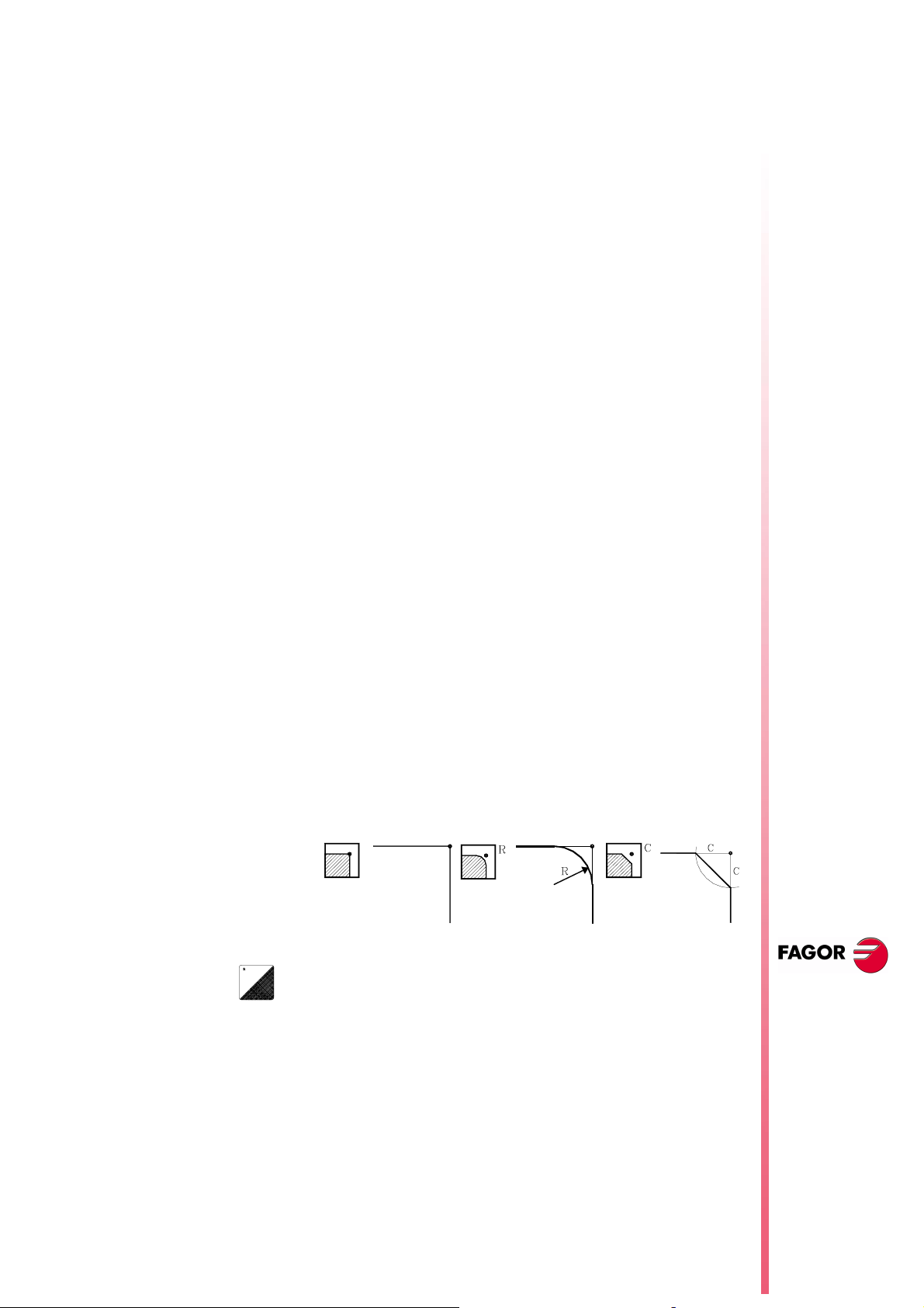
Threads with different entries
The threading range is completed with a new level (5) for multi-entry
threads.
Available when setting s.m.p. “M19TYPE (P43)=1”
The following must be defined:
The coordinates of the starting point (Xi, Zi)
The coordinates of the final point (Xf, Zf)
The pitch (P) and the depth (H) of the thread
The number of thread entries (N)
The distance to the end of the thread (σ)
The spindle angular position (Io)
In ISO mode, presently the threading cycles are G86 and G87, with
the new feature, a new parameter (V) with 4.0 format may be
entered to define the number of entries. It is an optional parameter
that goes at the end of the cycle and if not programmed or
programmed with a "0" value, it means that the thread only has one
entry. The syntax of the ISO instructions is now:
· G86-G87: X Z Q R I B [D L] C [J A V]
It does not affect thread repair.
39 TC model. Modifications to the grooving cycle
New level
8040 CNC
(a)
The grooving range is completed with a new level (5) for cut-off
operations.
The following must be defined:
The coordinates of the starting point (Xi, Zi)
The final cut-off diameter (φf)
The cut-off feedrate (F)
An intermediate diameter (φr) where the feedrate starts
slowing down.
The final cut-off feedrate (Fr)
The type of corner at the beginning of the cut-off.
A square corner. A rounding. A chamfer.
To modify the type of machining, place the cursor over this
icon and press the (a) key.
The cut-off begins in (Xi, Zi) and at the indicated feedrate (F). Up to
the intermediate diameter (φf), it is cut-off at the feedrate (F), but
from that point on, the feedrate slows down gradually until the final
diameter (φf) is reached at the feedrate (Fr).
NEW F
(S
OFT
EATURES
T: 8.XX)
When cutting-off, it is also possible to make a rounding, a chamfer
or leave it as a square corner.
TC model.
Modifications to
the grooving cycle
Page 35 of 46
Page 40

8040 CNC
40 TC model. Modifications in the profile cycle
Minimize the machining time in XC and ZC profile cycles
Until this version, after each roughing pass, the tool withdrew to the
safety position.
From this version on, this movement does not take place, thus
minimizing the execution time.
Starting point coordinates in XC and ZC profile cycles
From this version on, the CNC does not request the coordinates of
the starting point (X, C) because it assumes the first point of the
profile as the starting point of the cycle.
Finishing stock in XC and ZC profile cycles
When the finishing operation is carried out with tool compensation,
the following data must be defined:
Depth stock (δx) or (δz).
•
Side stock (δ) and the number of passes (N) to remove that stock
•
It is machined as follows:
Roughing operation leaving the indicated side stock (δ) and
•
depth stock (δx) or (δz).
Finishing of the bottom of the profile removing the finishing stock
•
(δx) or (δz).
Finishing of the side wall, removing the (δ) stock in (N) passes.
•
N
EW FEATURES
(S
T: 8.XX)
OFT
TC model.
Modifications in
the profile cycle
Page 36 of 46
Finishing tool in XC and ZC profile cycles
From now on, it is possible to use one tool for roughing and another
one for finishing, "T" and "D" fields.
This makes it possible to select a tool for the finishing operation that
could machine sideways.
41 TC model. Cycle selection
From this version on, it is possible to hide unused operations or
cycles and only show the used ones.
COCYF1 (P148)
COCYF2 (P149)
COCYF3 (P150)
COCYF4 (P151)
COCYF5 (P152)
COCYF6 (P153)
COCYF7 (P154)
COCYZ (P155)
COCYPOS (P156)
COCYPROF (P157)
COCYGROO (P158)
COCYF1
COCYF2 Turning 1 Turning 2
COCYF3 Facing 1 Facing 2
COCYF4 Taper turning 1 Taper turning 2 Taper turning 3
Each one of these g.m.p. is associated with an operation or cycle
and each one of their bits refers to each available level.
All the bits are initialized to "0", available option. To hide the desired
one, set the corresponding bit to "1".
bit 1 bit 2 bit 3 bit 4 bit 5
Page 41

bit 1 bit 2 bit 3 bit 4 bit 5
COCYF5 Rounding 1 Rounding 2
COCYF6 Threading 1 Threading 2 Threading 3 Threading 4 Threading 5
COCYF7 Grooving 1 Grooving 2 Grooving 3 Grooving 4 Cut-off
COCYZ Drilling 1 Drilling 2 Drilling 3 Drilling 4 Drilling 5
COCYPOS Positioning 1 Positioning 2
COCYPROF Profile 1 Profile 2 Profile 3 Profile 4
COCYGROO
8040 CNC
NEW F
EATURES
(S
T: 8.XX)
OFT
TC model. Cycle
selection
Page 37 of 46
Page 42

8040 CNC
User notes:
NEW F
EATURES
(S
T: 8.XX)
OFT
Page 38 of 46
Page 43

ERSION
V
8.11
1 Detected errors
A.m.p. DFORMAT (P1)
The installation manual shows wrong work units. The right work units
are:
Value Work units Format in
0 radius 5.3 5.3 4.4
1 radius 4.4 4.4 3.5
2 radius 5.2 5.2 5.3
3 radius It is not displayed
4 diameters 5.3 5.3 4.4
5 diameters 4.4 4.4 3.5
6 diameters 5.2 5.2 5.3
Connector X4. To connect the analog spindle
degrees
8040 CNC
Format in mmFormat in
inches
The installation manual shows the wrong function associated with
pins 11 and 12. The right pin values are:
Pin Signal and Function
1
2
3
4
5
6
7
8
9
10
11
12
13
14
15
Ac
/ Ac
Bc
/ Bc
I0c
/ I0c
ALc
/ ALc
+5 V
ConsCab
GND
GND
----
----
Chassis
Feedback signals
+5V output for feedback
Analog voltage output
0V output for feedback
0V output for the analog voltage
Shield
It admits TTL and differential TTL feedback.
Connector X5. To connect electronic handwheels
It admits TTL and differential TTL feedback.
Connector X10, X11, X12 and X13. Feedback inputs for the axes
It admits 1Vpp, TTL and differential TTL feedback.
NEW F
(S
OFT
EATURES
T: 8.1X)
Detected errors
Page 39 of 46
Page 44
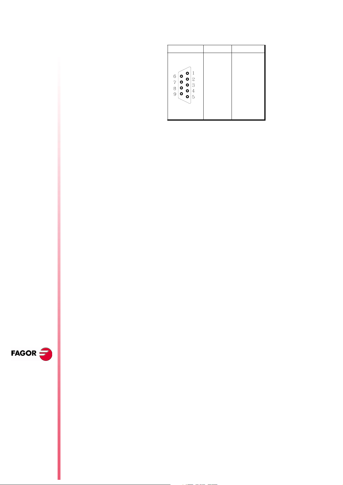
8040 CNC
Connector X1. RS232 serial line (8055i model)
From this version on, pin 9 no longer supplies 5V.
Variables POS(X-C) and TPOS(X-C)
The values of variables POS(X-C) and TPOS(X-C) are in the
following units.
They are read from the CNC in radius or diameter depending on
•
the setting of a.m.p. "DFORMAT (P1)".
They are always read in radius from the PLC.
•
Pin Signal
1 DCD
2RxD
3TxD
4DTR
5 GND ISO
6 ----7RTS
8CTS
9 -----
46
N
EW FEATURES
(S
T: 8.1X)
OFT
Detected errors
Page 40 of 46
Page 45

2 New validation codes
Due to new software options, the validation code changes from 16
to 24 characters. The new codes are also valid for the Memory
Cards with software versions older than V7.11
3 Smooth stop in probing move (G75/G76)
From this version on, a smooth stop may be defined for probing
moves. When the probe pulse is detected, the following error is not
reset, thus making the probe stop more smoothly.
8040 CNC
PROBEDEF (P168)
It defines the type of stop for the probing moves. It has 16 bits. Bit 16
selects the selected type of stop.
PROBEDEF xxxx xxxx xxxx xxx 0/1
0 Standard Stop.
1 Smooth stop.
By default 0
When setting the smooth stop, a.m.p "DERGAIN (P25)" and s.m.p.
"FFGAIN (P25)" should be set to zero. This may be done by setting
the range of gains through g.m.p. "ACTGAIN2 (P108)" with the bit
corresponding to G75/G76.
4 Square-corner or round-corner machining when changing
tool offset
When executing a tool change, the change takes place at the end of
the path. Using g.m.p. "TOOLTYPE (P167)" it is possible to define
how to machine the corner where the tool offset is being changed.
This corner may be machined in square corner (sharp) or rounded.
This parameter is only taken into consideration when working in
round corner. When working in square corner, the corner is always
machined in square corner mode.
TOOLTYPE (P167)
It has 16 bits. Bit 2 selects the type of corner.
TOOLTYPE x 0/1 xx xxxx xxxx xxxx
0 Square corner.
1 Round corner.
By default 0
NEW F
EATURES
(S
T: 8.1X)
OFT
New validation
codes
Page 41 of 46
Page 46

8040 CNC
5 New management of the distance-coded reference mark (I0)
From this version on, the distance-coded I0 via SERCOS may be
managed using the input of the drive's second feedback.
• The axis parameters to define the distance-coded I0 are at the
CNC.
I0TYPE (P52) I0CODI1 (P68) I0CODI2 (P69)
ABSOFF (P53) REFDIREC (P33) REFEED2 (P35)
AXISCHG (P16) LOOPCHG (P26)
We recommend to set axis parameter POSINREF=NO. Otherwise,
it generates a movement to the position defined by axis parameter
REFVALUE.
• The parameters related to the counting of pulses (feedback) are
at the drive. At FAGOR drives, the parameters are:
GP10 Feedback2Type
NP117 ResolutionOfFeedback2
NP118 ResolutionOfLinearFeedback
PP115.0 PositionFeedback2Type
The drive version must be V4.10 or V5.10 ( or greater).
46
N
EW FEATURES
(S
T: 8.1X)
OFT
6 Improved look ahead
Machining feedrate variations are now smoother thanks to filtered
acc/dec in short movements.
7 Leadscrew error compensation in both directions
Bidirectional leadscrew error compensation
From this version on, it is possible to define a different leadscrew
compensation for each moving direction.
This is defined in the leadscrew compensation tables. Each row of
the table contains the following data:
• The position of the axis to be compensated.
• The amount of error of the axis at that point. In the positive
direction.
• The amount of error of the axis at that point. In the negative
direction.
For each axis position, define the amount of error to compensate in
both directions. If the error in the negative direction has a zero value
in all positions, it is assumed that the error defined for the positive
direction is valid for both directions.
New management
of the distance-
coded reference
mark (I0)
Page 42 of 46
Likewise, the compensation defined in a single direction or for both,
the compensation error at the reference point does not need to be
zero.
Page 47

Software compatibility with respect to version V8.11:
i
• When updating from a version older than V8.11.
It maintains the values of the error in the positive direction of the
tables and assigns a zero error in the negative direction to all the
points.
• When changing to a version older than V8.11.
It maintains the error values in the tables in the positive direction, but
it loses the ones in the negative direction.
8 Parameters accessible from the oscilloscope or OEM
subroutine
8.1 Axis parameters that may be modified from the oscilloscope
The following axis machine parameters may be modified.
8040 CNC
Indicate the axis and the parameter number separated by a dot.
Example: [X.P18], [Z.P23].
Number Parameter Update
P42 MAXFEED Beginning of the next block
P43 JOGFEED Beginning of the next block
8.2 General parameters modifiable from the oscilloscope
The following general machine parameter (needed to adjust the
machine) may be modified from the oscilloscope.
Enter the indicator of the general parameter and the parameter
number separated with a dot. Example: [G.P161].
Number Parameter Update
P161 TLOOK Beginning of the execution of a program.
8.3 Machine parameters modifiable from an OEM program
All the parameters modifiable from the oscilloscope can also be
changed from an OEM program using the following variables.
MPGn MP(X-C)n MPSn
MPSSn MPASn MPLCn
NEW F
EATURES
The new values are updated according to the tables described in
chapter
[RESET] or [SHIFT]+[RESET] to update the values.
30 Oscilloscope function
It is not necessary to press
(S
T: 8.1X)
OFT
Parameters
accessible from the
oscilloscope or
OEM subroutine
Page 43 of 46
Page 48
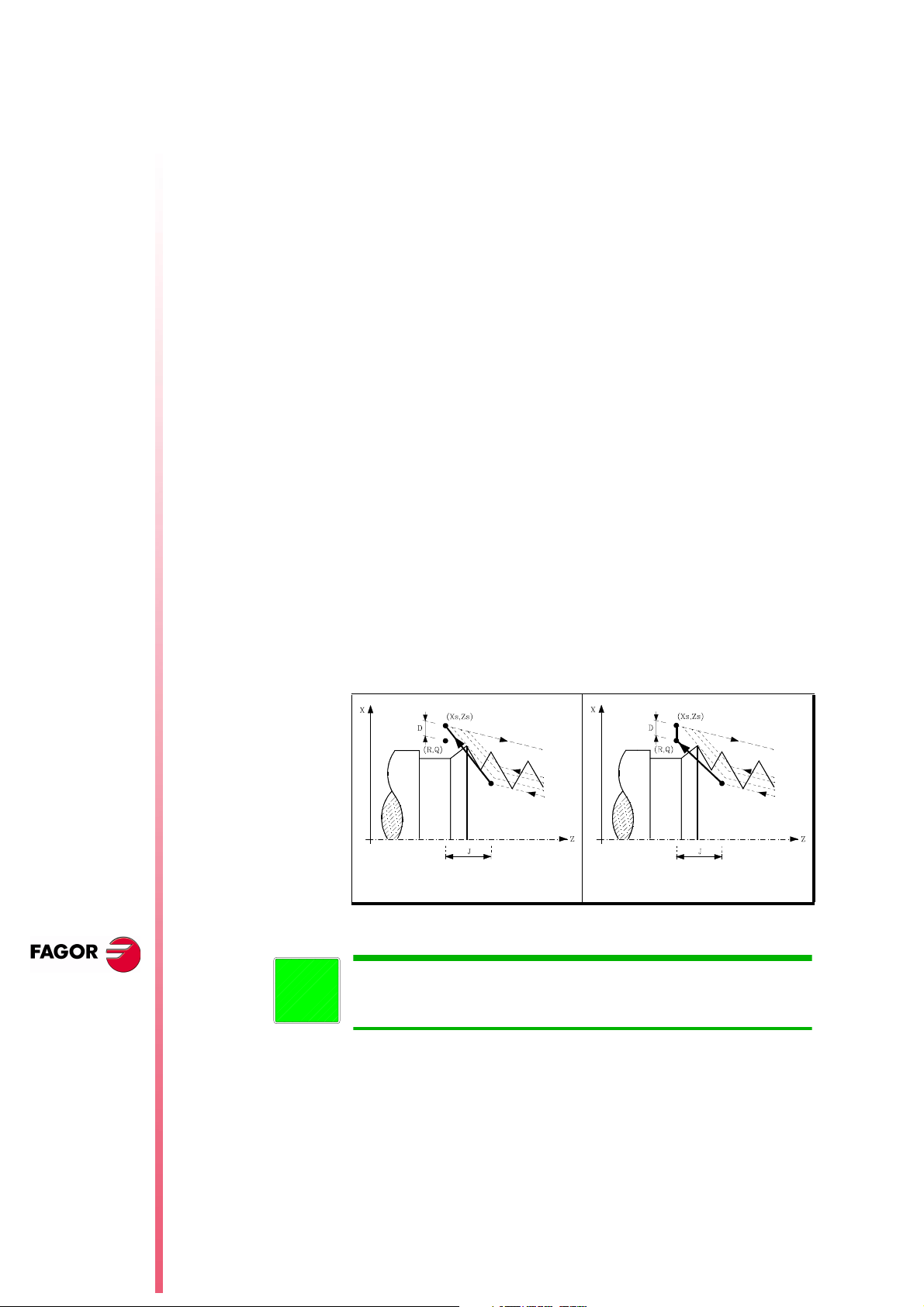
9 Sampling period
From this version on, on the 8055/C and 8055i/C models that do not
have the CPU turbo, it is possible to set a sampling period of 2
milliseconds g.m.p. “LOOPTIME (P72)”.
8040 CNC
The following values may be allocated to plc.m.p. "CPUTIME (P26)
that sets the time the System CPU dedicates to the PLC when
programming a "LOOPTIME = 2 ms":
CPUTIME = 0 1 ms every 8 samplings, every 16 ms
CPUTIME = 1 1 ms every 4 samplings, every 8 ms
CPUTIME = 2 1 ms every 2 samplings, every 4 ms
10 Thread exit going through the end point
It affects the "end of thread" parameter of canned cycles G86 and
G87.
G86 Longitudinal threading cycle
G87 Face threading cycle
The "end of thread" parameter (J) defines the beginning of the end
of the thread. It may be set with either a positive or negative value.
Parameter "J" positive.
•
If programmed with a positive value, the tool moves directly from
the "J" point to the safety distance Xs, Zs.
Parameter "J" negative.
•
The tool moves from the "J"point to the end of the thread (R,Q),
and then to the safety distance Xs.
By default 0
46
N
EW FEATURES
(S
T: 8.1X)
OFT
Sampling period
Page 44 of 46
i
J > 0 J < 0
At the TC model, this change affects all five threading levels. The "end
of thread" parameter may be defined with either a positive or negative
value. It works just as described earlier.
Page 49

User notes:
8040 CNC
NEW F
EATURES
(S
T: 8.1X)
OFT
Page 45 of 46
Page 50

8040 CNC
User notes:
NEW F
EATURES
(S
T: 8.1X)
OFT
Page 46 of 46
Page 51

Operating Manual
(TC option)
Ref. 0204-ing
Page 52

The information described in this manual may be subject to variations
due to technical modifications.
FAGOR AUTOMATION, S.Coop. Ltda. reserves the right to modify
the contents of the manual without prior notice.
iii
Page 53

INDEX
1. GENERAL CONCEPTS
1.1 Keyboard ..................................................................................................................1
1.2 General ......................................................................................................................2
1.2.1 Management of text program P999997 .......................................................................4
1.3 Power-up ...................................................................................................................5
1.4 Operating in T mode with TC keyboard.....................................................................6
1.5 Video OFF..................................................................................................................6
1.6 Handling the CYCLE-START key ..............................................................................6
2. OPERATING IN JOG MODE
2.1 Introduction ..............................................................................................................2
2.2 Axis Control ..............................................................................................................6
2.2.1 Work Units ...............................................................................................................6
2.2.2 Coordinate preset ......................................................................................................6
2.2.3 Handling the Feedrate of the Axes (F) .......................................................................6
2.3 Home search (Machine reference zero ) .....................................................................7
2.4 Jogging the axes ........................................................................................................8
2.4.1 Continuous jog ..........................................................................................................8
2.4.2 Incremental jog..........................................................................................................9
2.4.3 Jogging with an Electronic Handwheel......................................................................10
2.4.3.1 Standard handwheel mode ........................................................................................11
2.4.3.2 Path handwheel mode ...............................................................................................12
2.4.3.3 Feed handwheel mode...............................................................................................13
2.5 Tool control ...............................................................................................................14
2.5.1 Tool change...............................................................................................................15
2.5.1.1 Variable tool change point.........................................................................................16
2.5.2 Tool calibration..........................................................................................................17
2.5.2.1 Modify values during execution................................................................................20
2.5.3 Live tool ....................................................................................................................21
2.6 Spindle Control..........................................................................................................23
2.6.1 Spindle in RPM..........................................................................................................24
2.6.2 Constant Surface Speed ............................................................................................25
2.6.2.1 Operating at Constant Surface Speed (CSS)..............................................................26
2.6.3 Spindle orientation ....................................................................................................27
2.6.3.1 Operation with spindle orientation ............................................................................28
2.7 Control of external devices ........................................................................................29
2.8 Handling ISO code ....................................................................................................30
v
Page 54

3. OPERA TING WITH OPERA TIONS OR CYCLES
3.1. Operation edit mode ..................................................................................................2
3.1.1 Definition of spindle conditions ................................................................................3
3.1.2 Definition of machining conditions ...........................................................................4
3.1.3 Cycle level .................................................................................................................5
3.2 Simulating and executing the cycle ...........................................................................6
3.2.1 Background editing of cycles ....................................................................................6
3.3 Positioning cycle .......................................................................................................7
3.3.1 Definition of data.......................................................................................................8
3.4 Turning cycle ............................................................................................................9
3.4.1 Definition of geometry...............................................................................................9
3.4.2 Basic operation..........................................................................................................10
3.5 Facing cycle ..............................................................................................................12
3.5.1 Definition of geometry...............................................................................................12
3.5.2 Basic operation..........................................................................................................13
3.6 Taper cycle ................................................................................................................15
3.6.1 Definition of geometry...............................................................................................16
3.6.2 Basic operation..........................................................................................................19
3.7 Rounding cycle .........................................................................................................21
3.7.1 Definition of geometry...............................................................................................22
3.7.2 Basic operation..........................................................................................................25
3.8 Threading cycle.........................................................................................................27
3.8.1 Definition of geometry...............................................................................................29
3.8.2 Definition of the type of machining ...........................................................................31
3.8.3 Longitudinal threading. Basic operation....................................................................32
3.8.4 Taper threading. Basic operation. ..............................................................................33
3.8.5 Face threading. Basic operation ................................................................................34
3.8.6 Thread repair. basic operation ...................................................................................35
3.9 Grooving cycle ..........................................................................................................36
3.9.1 Calibration of the grooving tool ................................................................................38
3.9.2 Definition of geometry...............................................................................................39
3.9.3 Basic operation..........................................................................................................42
3.10 Drilling and tapping cycles ........................................................................................44
3.10.1 Definition of geometry...............................................................................................46
3.10.2 Basic operation. Drilling cycle ...................................................................................48
3.10.3 Basic operation. Tapping cycle .................................................................................49
3.10.4 Basic operation. Multiple DRILLING cycle................................................................50
3.10.5 Basic operation. Multiple tapping cycle ....................................................................52
3.10.6 Basic operation. Multiple slot milling cycle ............................................................... 53
3.11 Profile cycle ...............................................................................................................54
3.11.1 Level 1. Profile definition ........................................................................................... 55
3.11.2 Level 2. Profile definition ........................................................................................... 56
3.11.3 Level 2. Optimizing of the machining of a profile ....................................................... 57
3.11.4 Geometry definition. Levels 1, 2. ZX profile...............................................................58
3.11.5 Basic operation. Levels 1,2. ZX profile ......................................................................61
3.11.6 Level 1. Example ........................................................................................................62
3.11.7 Level 2. Examples.......................................................................................................63
vi
Page 55

4. PROGRAM STORAGE
4.1 List of stored programs .............................................................................................2
4.2 See content of a program........................................................................................... 3
4.2.1 Seeing the operations in detail ..................................................................................3
4.3 Edit a new part-program ............................................................................................4
4.3.1 Storage of an ISO block or a cycle.............................................................................4
4.4 Erasing a part-program ..............................................................................................5
4.5 Copy a part-program in another.................................................................................5
4.6 Modifying a part-program .........................................................................................6
4.6.1 Erasing an operation .................................................................................................6
4.6.2 Moving an operation to another position .................................................................6
4.6.3 Adding or inserting a new operation.........................................................................7
4.6.4 Modifying an already existing operation ...................................................................7
5. EXECUTION AND SIMULA TION
5.1 Simulating or executing an operation or cycle ...........................................................2
5.2 Simulating or executing a part-program .....................................................................3
5.2.1 Simulating or executing a section of a part-program..................................................3
5.3 Simulating or executing a stored operation................................................................3
5.4 Execution Mode ........................................................................................................4
5.4.1 Tool inspection ..............................................................................................................5
5.5 Graphic representation ..............................................................................................6
vii
Page 56

TC work mode
1.1 KEYBOARD
1. General Concepts
1.1 Keyboard
1. GENERAL CONCEPTS
speed
Alphanumeric keys and command keys.
Selects character X
Selects character A
Selects character R
Specific keys for the TC model
Enable Selection and definition of Machining Operations
Governing external devices
Selecting the spindle’s operating mode
Selecting single or automatic execution mode
The JOG key
Enables Moving the axes of the machine
Governing the spindle
Modifying the feedrate of the axes and the spindle
Starting and stopping execution
Chapter 1 - page 1
Page 57

1. General Concepts
1.2 General
TC work mode
1.2 GENERAL
It has all the performance features of the T model plus the specific features of the TC mode.
For example, the setting of the numerical Control must be done in "T" mode.
In the TC operating mode the programs P900000 to P999999 are reserved for the CNC itself, that is,
these cannot be used as part-programs by the user as they have a special significance.
Furthermore, to be able to work in TC mode, the CNC has to have in its memory programs P999997
and P999998, which are supplied by Fagor Automation.
Every time the CNC detects a new software version, updates these programs automatically and makes
a backup copy of the old ones in the "Memkey Card" (CARD A).
Also routines 0000 a 8999 are free for use and routines 9000 to 9999 are reserved for the CNC itself.
Some of the programs reserved for the CNC itself have the following meaning:
Warning: Programs P999997 and P999998 are associated with the software version.
Fagor Automation shall not be held responsible of any possible malfunction if
programs P999997 and P999998 have been deleted from memory or do not
correspond to the software version.
Some of the routines reserved for the CNC itself have the following meaning:
9998 Routine to be executed by the CNC at the beginning of each part-program.
9999 Routine to be executed by the CNC at the end of each part-program.
Every time a new part-program is edited the CNC adds a call to the corresponding
routine at the beginning and end of each program.
Warning Both subroutines must be defined by the machine manufacturer even if no operation
is to be carried out at the beginning or at the end of the part-program.
Otherwise, the CNC will issue an error when attempting to run a part-program.
Example of how to define subroutine 9998.
(SUB 9998) ; Definition of subroutine 9998.
; Programmed blocks defined by the machine manufacturer
(RET) ; End of subroutine
Chapter 1 - page 2
Page 58

TC work mode
1. General Concepts
1.2 General
Some of the programs reserved for the CNC itself have the following meaning:
P999998 This is a routines program used by the CNC for interpreting the programs edited in TC
format and executing these afterwards.
Warning
No modifications of this program are allowed. If this program is
modified, Fagor Automation will not be held responsible for the
performance of the CNC.
If the manufacturer needs to create his own subroutines (home
search subroutine, tool change, etc. ...) as well as subroutines
9998 and 9999 should be included in another program, for
example P999999.
P999997 This is a text program which contains:
All the phrases and texts displayed on the different screens in the TC mode.
The help texts for the icons in work cycles shown at the bottom left side of the screen.
The messages (MSG) and errors (ERR) to be issued at the TC model.
All these texts, messages and errors may be translated into the desired language.
Points to consider:
All the lines of the program have to start with the character ";"
If a line starts with ";;", the CNC will understand that the whole line is a program
comment.
The format of a line is as follows:
";Nr. of text - explanatory remark (not displayed) - $Text to be displayed"
Examples
;; General text ...............................The CNC treats this as a remark
;;44 Feedrate $M/MIN .................The CNC treats this as a remark.
;44 $M/MIN ..................................This is message 44 and the text "M/MIN" is
displayed
;;44 Feedrate $M/MIN .................This is message 44, and has the explanatory
remark "Feedrate" which is not displayed and the
text
"M/MIN" is shown.
Notes regarding messages:
The format must be respected. Only the text after "SAVEMSG:" may be translated
Example:
Original: N9500(MSG"SAVEMSG: TURNING CYLE")
Translated: N9500(MSG"SAVEMSG: ZILINDRAKETA ZIKLOA")
Notes regarding errors:
The format must be respected. Only the text between quotes( "xxxx") may be
translated
Example:
Original: N9000(ERROR"Cycle with neither roughing nor finishing operation")
Translated: N9000(ERROR"Arbastatu eta Akabatu gabeko zikloa")
Warning
When modifying program 999997, it is recommended to make a
backup copy because the CNC replaces it every time another
language is selected or the software version is updated.
P998000 ... P998999 These are user-defined profile part-programs. In TC mode the user defines
them with 3 digits, (from 0 to 999) and the CNC saves these internally as P 998xxx.
Chapter 1 - page 3
Page 59

1. General Concepts
1.2 General
1.2.1 System of coordinates
TC work mode
1.2.1 MANAGEMENT OF TEXT PROGRAM P999997
On power-up, the CNC copies the texts of program P999997 into the system memory.
It checks if program P999997 is in the user memory. If it is not, it looks in "CARD A", if it is not
there either, it assumes the ones provided by default and it copies them into the P999997 program
of the user memory.
If the mainland Chinese language is selected, program P999997 is ignored. It always assumes the
ones provided by default.
If when switching from M mode to MC or MCO mode, program P999997 cannot be found, because
it has been erased, it is re-initialized like after power-up.
After modifying the texts of program P999997, turn the CNC off and back on to assume the new texts.
When changing a language, software version or adding conversational modes MC, MCO (new
software features) the CNC carries out the following operations:
The texts that were being used are saved into "CARD A" as program P999993.
Program P999997 is erased from "CARD A"
The new default texts are assumed and are copied into program P999997 of the user memory.
When changing the texts, turn the CNC off and back on after modifying program P999997 so it
assumes the new texts.
Chapter 1 - page 4
Page 60

TC work mode
1. General Concepts
1.3 Power-up
1.3 POWER-UP
Both on CNC power-up and after the keystroke sequence: the CNC acts as follows:
Shows «page 0» if it has been defined by the manufacturer. To access this operating mode, press
any key.
If there is no «page 0», the CNC will display the standard screen for the selected work mode.
There are two operating modes: TC mode and T mode. To switch from one mode to the other, press
The standard TC mode screen is:
Warning
CNC setting should be done in T mode.
Some errors should also be removed in T mode.
Chapter 1 - page 5
Page 61

1. General Concepts
1.4 Operating in T mode with TC keyboard
1.5 Video OFF
TC work mode
1.4 OPERATING IN T MODE WITH TC KEYBOARD
The TC keyboard has been designed to also operate in T mode. The alphanumeric keyboard must
be used for the keys replacing softkeys F1 to F7.
Alphanumeric keyboard:
The keys which replace softkeys F1 to F7 are:
To toggle from operating mode to the other press key sequence
1.5 VIDEO OFF
The CRT can be blanked out by hitting the keystroke sequence: .
To recover the video signal, just press any key.
On the other hand, when receiving any message (PLC, program, etc.) the CNC also recovers the
display.
1.6 HANDLING THE CYCLE-START KEY
In order to avoid unwanted executions when keying sequences not supported in the TC mode, the
CNC changes the color of the "CYCLE START" icon located at the top of the window from green
to grey and it shows a message indicating that it is an invalid action.
For example, if while a part-program is selected, "M3 Start" is pressed, (sequence not supported by
the TC model), the CNC displays a warning message and prevents the part-program from running
when detecting the "cycle start" key.
Chapter 1 - page 6
Page 62

TC work mode
The standard TC operating mode screen is:
2. Operating in JOG mode
2. OPERA TING IN JOG MODE
If one presses key
The CNC displays the special TC operating mode screen.
Chapter 2 - page 1
Page 63

2. Operating in JOG mode
2.1 Introduction
2.1 INTRODUCTION
The standard TC operating mode screen contains the following information:
TC work mode
1.- Clock
2.- This window can display the following data:
SBK when the Single Block execution mode is selected.
DNC when the DNC mode is activated.
P..... number of the program selected.
Message «In Position» - «Execution» - «Interrupted» - «RESET»
PLC messages
3.- The CNC messages are shown in this window.
4.- This window can display the following data:
* The X, Z coordinates of the axes. The ? symbol indicates that the axis is working in diameters.
* In small characters, the axis coordinates referred to machine zero reference (home). This
values are very useful when allowing the operator to set a tool change position (see zone 6).
The CNC does not show this data when text 33 has not defined in program 999997.
* The coordinates of the auxiliary axes which are defined.
* The real spindle rpm, S1000 or the real rpm of the second spindle, S2 1000
5.- The information shown in this window depends on the position of the left-hand switch.
In all cases it shows the feedrate of the «F» axes that has been selected and the % of F being
applied.
When Feed-hold is active, the value of the feedrate changes colors.
All the possible cases are shown next.
Chapter 2 - page 2
Page 64
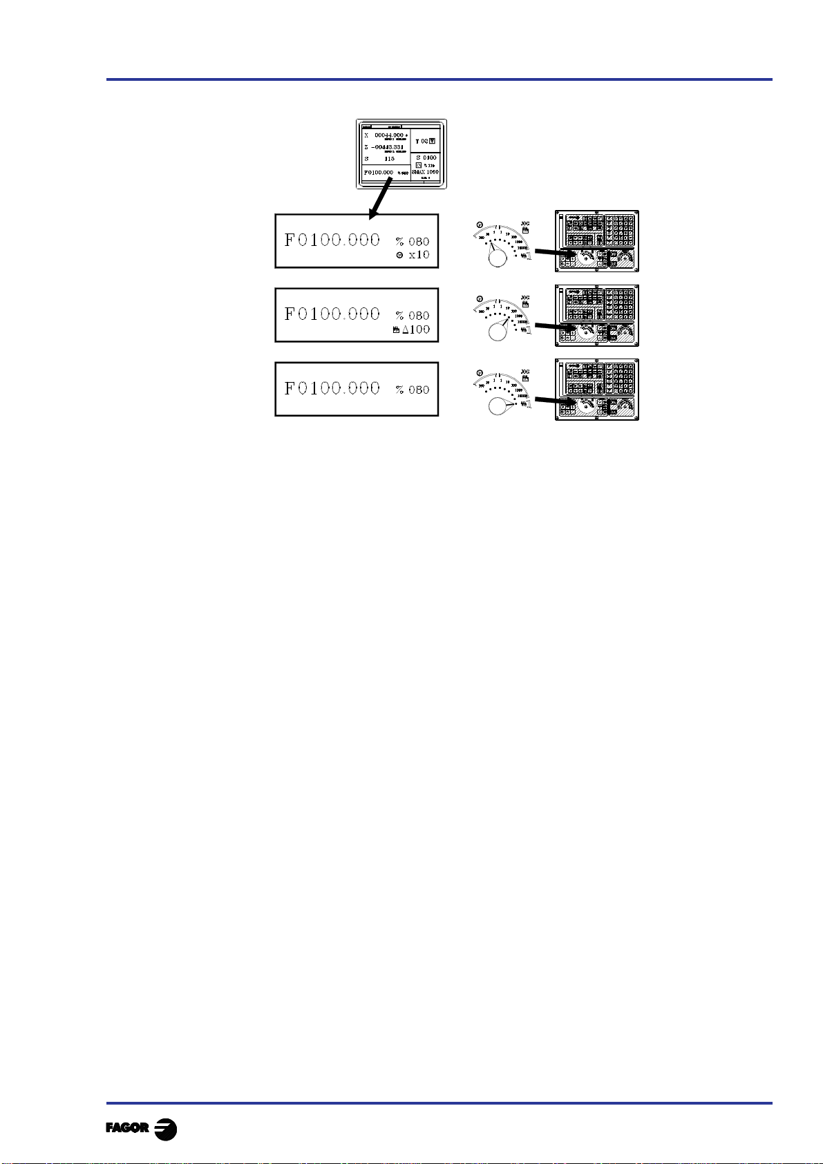
TC work mode
2. Operating in JOG mode
2.1 Introduction
6.- This window displays, in large characters, the tool number «T» selected.
The graphic representation corresponding to the location code associated with the tool.
The offset number «D» associated with the tool. If the tool number and the offset number
coincide, the CNC will not display value «D».
The coordinates for the tool change point referred to home. The CNC does not display this
window when text 47 of program 999997 is not defined.
7.- This window shows all the details of the spindle :
* The theoretical turning speed selected. «S» value when working in rpm. and «CSS» value
when working at constant surface speed.
* The condition of the spindle. This is represented by an icon and can be turning to the right,
to the left or idle.
* The % of the spindle speed being applied.
* The maximum revolutions of the spindle.
* The range of spindle active.
* The range of the active spindle. The CNC does not display this information when text 28 of
program 999997 is not defined.
8.- Angular increment when working in spindle orientation mode.
9.- Whenever a work cycle is accessed, the CNC shows the help text associated with the icon
selected in this window.
This help text must be defined in P999997 program and be written in the language required.
The format and the points to be considered in the P999997 program are detailed in the chapter
on "General concepts".
10.- Reserved.
Chapter 2 - page 3
Page 65

2. Operating in JOG mode
2.1 Introduction
The special screen for TC operating mode contains the following information:
TC work mode
1.- Clock
2.- This window can display the following data:
SBK when the Single Block mode of execution is selected.
DNC when the DNC mode is active.
P..... number of the program selected.
Message «In Position» - «Execution» - «Interrupted» - «RESET»
PLC messages
3.- The CNC messages are shown in this window.
4.- In manual operating mode this window does not display any data, but during execution, it shows
the lines of the program being executed.
5.- The X, Z and C axes have the following fields:
COMMAND States the coordinate programmed, that is, the position that the axis must
reach.
ACTUAL States the actual coordinate or actual position of the axis.
TO GO States the distance that the axis has still to go to reach the coordinate
programmed.
FOLLOWING ERROR Difference between the theoretical and real values of the position.
The spindle (S) has the following fields available:
THEORETICAL theoretical speed S programmed.
RPM speed in rpm.
M/MIN speed in meters/ minute.
FOLLOWING ERROR When operating with spindle guided stop (M19) this indicates the
difference between theoretical and real speeds.
The auxiliary axes only show the actual position of the axis
Chapter 2 - page 4
Page 66
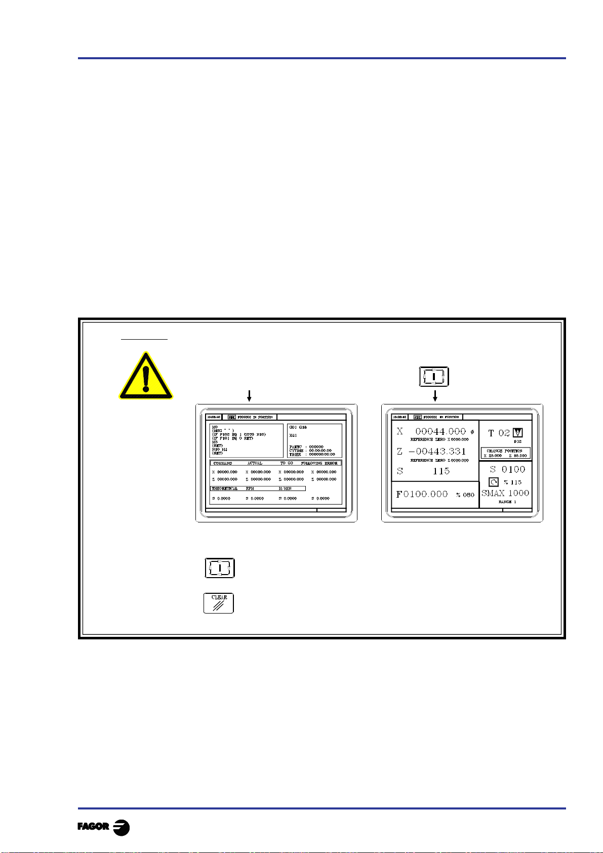
TC work mode
6.- This window shows the state of the «G» functions and the auxiliary functions «M» that are
activated. It also displays the value of variables.
PARTC States the number of consecutive parts that have been executed with the same
program.
Whenever a new program is selected, this variable assumes value 0.
CYTIME States the time elapsed during the execution of the parts. It is expressed in the
following format: “hours : minutes : seconds : hundredths of second”.
Whenever the execution of a program is started, even though this is repetitive, this
variable assumes value 0.
TIMER States the reading of the clock enabled by the PLC. It is expressed in format “hours
: minutes : seconds”.
7.- Reserved.
8.- Reserved.
2. Operating in JOG mode
2.1 Introduction
Warning
Whenever a part-program or an operation stored as part of a part-program is
selected for simulation or execution, the CNC selects this part-program in the
top center window and highlights it next to the symbol.
When the selected program is highlighted, the CNC acts as follows:
If is pressed, the CNC executes the selected part-program.
If is pressed the program is de-selected, the CNC deletes it from the top
center window.
Chapter 2 - page 5
Page 67

2. Operating in JOG mode
2.2 Axis control
TC work mode
2.2 AXIS CONTROL
2.2.1 WORK UNITS
Whenever the TC work mode is accessed, the CNC assumes the work units, «mm or inches», «radii
or diameters», «millimeters/minute or millimeters/revolution», etc., that are selected by machine
parameter.
To modify these values, the "T" mode has to be accessed, modifying the relevant machine parameter.
2.2.2 COORDINATE PRESET
Coordinate preset must be made axis to axis, in the following stages:
1st Press the key for the axis required or
The CNC will frame the position for said axis, to indicate that this is selected.
2nd Enter the value required for preset of the axis.
To exit coordinate preset press
3rd Press so that the CNC assumes said value as the new value for the point.
The CNC requests confirmation of the command. Press to confirm or to
exit preset.
2.2.3 HANDLING THE FEEDRATE OF THE AXES (F)
To fix any particular value for the axis feedrate the following steps have to be carried out:
1st Press
The CNC will frame the present value, to indicate that this is selected.
2nd Enter the new feedrate required.
To exit coordinate preset press
3rd Press for the CNC to assume said value as the new feedrate for the axes.
Chapter 2 - page 6
Page 68

TC work mode
2. Operating in JOG mode
2.3 Home search
2.3 HOME SEARCH (MACHINE REFERENCE ZERO )
Home search can be done in 2 ways:
- Home search on all the axes.
- Home search on a single axis.
Home search on all the axes
To carry out a search for machine reference zero for all axes the user should press key:
The CNC will request confirmation of the command (text 48 of program 999997)
Press ,The CNC will execute the machine reference zero routine defined by the
manufacture in the general machine parameter P34 (REFPSUB).
Warning: After carrying out the search for machine reference zero (home)
position in this mode, the CNC saves the part zero or zero offset that
is active at the time.
A home search routine, general machine parameter P34 other than 0 has
to be defined. Otherwise the CNC will display the relevant error.
Home search on a single axis
To carry out the search for machine reference zero for only one axis the key for the required axis
should be pressed as well as the key for machine reference zero search.
In either case, the CNC will request confirmation of the command (text 48 of program 999997)
Carries out the home search on the X axis
Carries out the home search on the Z axis
Warning: After carrying out the search for machine home position in this mode
the CNC does not save the part zero or zero offset that is active at the
time and assumes as new part zero the position taken by machine
reference zero (home).
Chapter 2 - page 7
Page 69

2. Operating in JOG mode
2.4 Jogging the axes
2.4.1 Continuous jog
TC work mode
2.4 JOGGING THE AXES
The axes of the machine can be moved in the following ways:
- [X] [target position] or [Z] [target position]
- continuous jog
- incremental jog
- jogging with an electronic handwheel
2.4.1 CONTINUOUS JOG
Place the left-hand switch in position and on the right-hand switch select the percentage (0%
to 120%) of the feedrate selected to be applied.
Continuous movement should be done axis to axis. To do this press the JOG
key for the direction of the axis to be moved.
The axis moves with a feedrate equal to the percentage (0% to 120%) of the «F»
feedrate selected.
If during movement the key is pressed the maximum feedrate possible is carried out, as is stated
in the “G00FEED” axis machine parameter. This feedrate will be applied as long as said key is
pressed, and when released the previous feedrate will be resumed.
Depending on the state of the “LATCHM” general logic input the movement will be made in the
following way:
* If the PLC sets this mark at a low logic level (0V), the axis will only move while the relevant
JOG key is pressed.
* If the PLC sets this mark at a high logic level (24V), the axis will start to move when the JOG
key is pressed and will not stop until said JOG key or another JOG key is pressed again, and in
this case the movement is transferred to what is indicated by the next key pressed.
When operating with feedrate "F" in millimeters/revolution the following cases may arise:
a) The spindle is started. or
The CNC moves the axes to the F programmed.
b) The spindle is stopped but there is a spindle speed S selected.
The CNC calculates the feedrate in millimeters/minute corresponding to the theoretical "S" and
moves the axis.
For example, if «F 2.000» and «S 500»:
Feedrate = F (mm/rev.) x S (rev/min)= 2 x 500 = 1000 mm/min
The axis moves at a feedrate of 1000 in millimeters/minute.
c) The spindle is stationary and there is no spindle speed S selected.
If feedrate F has value 0, the CNC moves the axes at rapid feedrate.
If feedrate F has any other value, the axes will only be able to be moved if key is pressed
and the key for one axis. The CNC moves the axis at fast feedrate.
Chapter 2 - page 8
Page 70

TC work mode
2. Operating in JOG mode
2.4 Jogging the axes
2.4.2 Incremental jog
2.4.2 INCREMENTAL JOG
Place the left-hand switch in one of the positions
Incremental movement must be done axis to axis. To do this press the JOG key for the direction of
the axis to be moved.
Each time a key is pressed, the corresponding axis moves the amount set by the switch. This
movement effects the «F» feedrate selected.
Position of the switch Movement per turn
1 0.001 mm or 0.0001 inches
10 0.010 mm or 0.0010 inches
100 0.100 mm or 0.0100 inches
1000 1.000 mm or 0.1000 inches
10000 10.000 mm or 1.0000 inches
Chapter 2 - page 9
Page 71

2. Operating in JOG mode
2.4 Jogging the axes
2.4.3 Jogging with an electronic handwheel
2.4.3 JOGGING WITH AN ELECTRONIC HANDWHEEL
The various handwheel configurations are:
General handwheel It can be used to jog any axis one by one.
Select the axis and turn the handwheel to move it.
Individual handwheel: It replaces the mechanical handwheels.
Up to 3 handwheels can be used (one per axis).
It only moves the axis it is associated with.
To move any of them, turn the switch to any of the handwheel positions.
Positions 1, 10 and 100 indicate the multiplying
factor being applied besides the internal x4 to
the feedback pulses supplied by the electronic
handwheel.
For example, if the manufacturer has set a
distance of 0.100 mm or 0.0100 inches per
handwheel turn, thus:
TC work mode
Switch position Distance per turn
1 0.100 mm or 0.0100 inch
10 1.000 mm or 0.1000 inch
100 10.000 mm or 1.0000 inch
Warning:
When operating with individual handwheels and depending on how fast the handwheel is
turned and on the selected handwheel switch position, the CNC might be demanded to
move the axis faster than the maximum permitted. In that case, the CNC will move the axis
the indicated distance but it will limit the axis speed to that maximum value.
There are 3 operating modes with handwheels:
Standard handwheel:
With the general handwheel, select the axis to be moved and turn the
handwheel.
With individual handwheels, turn the handwheel associated with the axis to be
moved.
Path handwheel: For chamfering and rounding corners.
2 axes are moved along a selected path (chamfer or rounding) by moving a
single handwheel.
This feature must be activated via PLC.
The general handwheel is assumed as the "path handwheel" or the individual
handwheel associated with the Z axis.
Feed handwheel To control the feedrate of the machine.
Chapter 2 - page 10
This feature must be activated via PLC.
Page 72

TC work mode
2.4.3.1 STANDARD HANDWHEEL MODE
With the general handwheel proceed as follows:
1.- Select the axis to be jogged.
Press one of the JOG keys of the axis to be jogged. The selected axis will be highlighted.
When using a FAGOR handwheel with an axis selector button, the axis may be selected as
follows:
Push the button on the back of the handwheel. The CNC select the first axis and it highlights it.
When pressing the button again, the CNC selects the next axis and so on in a rotary fashion.
To deselect the axis, hold the button pressed for more than 2 seconds.
2.- Jog the axis
Once the axis has been selected, it will move as the handwheel is being turned and in the direction
indicated by it.
2. Operating in JOG mode
2.4 Jogging the axes
2.4.3 Jogging with an electronic handwheel
With individual handwheels:
Each axis will move as the corresponding handwheel is being turned according to the switch position
and in the direction indicated by it.
With several simultaneous handwheels:
The machine may have a general handwheel and up to 3 individual handwheels associated with each
axis.
The individual handwheels have priority over the general handwheel. So, if an individual handwheel
is moving, the general handwheel will be ignored.
Chapter 2 - page 11
Page 73

2. Operating in JOG mode
2.4 Jogging the axes
2.4.3 Jogging with an electronic handwheel
TC work mode
2.4.3.2 PATH HANDWHEEL MODE
With this feature, it is possible to jog two axes at the same time along a linear path (chamfer) or circular
path (rounding) with a single handwheel.
The CNC assumes as the path handwheel the general handwheel or, when this one is missing, the one
associated with the Z axis.
This feature must be handled by the manufacturer of the machine.
While in handwheel mode and selecting the “path handwheel”, the CNC shows the following data:
When choosing a linear jog (upper drawing) , the angle of the path must be indicated and when
choosing a circular jog (lower drawing), the arc center coordinates must be indicated in radius.
To define these variables, press the [F] and, then, one of these keys:
Example: The [O2] key is used to activate or deactivate the "path handwheel" mode and the [O3] key
to indicate the type of movement.
DFU B29 R561 = CPL M5054 Activate / deactivate the "path handwheel" mode
DFU B31 R561 = CPL M5053 Selects the type of movement, along a straight line or an arc
Chapter 2 - page 12
Page 74

TC work mode
2. Operating in JOG mode
2.4 Jogging the axes
2.4.5 Master Handwheel
2.4.3.3 FEED HANDWHEEL MODE
Usually, when making a part for the first time, the machine feedrate is controlled by means of the
feedrate override switch.
From this version on, it is also possible to use the machine handwheels to control that feedrate. This
way, the machining feedrate will depend on how fast the handwheel is turned.
To do this, proceed as follows:
Inhibit all the feedrate override switch positions from the PLC.
Detect how far the handwheel is turned (reading of pulses received)
Set the corresponding feedrate from the PLC depending on the pulses received from the
handwheel.
The following CNC variables return the number of pulses the handwheel has turned.
HANPF shows the number of pulses of the 1st handwheel.
HANPS shows the number of pulses of the 2nd handwheel.
HANPT shows the number of pulses of the 3rd handwheel.
HANPFO shows the number of pulses of the 4th handwheel.
To use this feature, the handwheel must be associated with one of the axes of the machine. General
machine parameters “AXIS1....8” or “HANDWHE1....4” set with values: “21....29”
Example: The machine has a button to activate and deactivate this feature (feed handwheel) and the
feedrate control is carried out with the second handwheel.
CY1
R101=0 Resets the register containing the previous handwheel
reading
END
PRG
DFU I71 = CPL M1000 Every time the button is pressed, mark M1000 is inverted
M1000 = MSG1 If the feature is active, a message is displayed.
NOT M1000 If the feature is not active
= AND KEYDIS4 $FF800000 KEYDIS4 enables all the positions of the feedrate override
switch
= JMP L101 and goes on with program execution
If the feature is active
DFU M2009 and a leading edge (up flank) occurs at the clock mark
M2009
= CNCRD(HANPS,R100,M1) We read the number of handwheel pulses contained in
R100
= SBS R101 R100 R102 calculates the number of pulses received from the last
reading
= MOV R100 R101 updates R101 for the next reading
= MLS R102 3 R103 calculates in R103 the proper % of feedrate override
= OR KEYDIS4 $7FFFFF KEYDIS4 inhibits all the other positions of the feedrate override
switch
CPS R103 LT 0 = SBS 0 R103 R103 ignores the handwheel turning direction
CPS R103 GT 120 = MOV 120 R103 Limits the maximum feedrate override to 120%.
DFU M2009 With the leading edge (up flank) of the clock mark
M2009
= CNCWR(R103,PLCFRO,M1) set the calculated feedrate override (PLCFRO=R103)
L101
END
Chapter 2 - page 13
Page 75

2. Operating in JOG mode
2.5 Tool control
TC work mode
2.5 TOOL CONTROL
The standard screen for TC operating mode displays the following information about the tool.
CHANGE POSITION
This window displays the following information:
> In large characters, the number "T" of the selected tool and a graphic representation of its tip.
> The offset number «D» associated with the tool.
> The selected rpm "S" for the live tool .
This value is only displayed when a live tool is selected.
> The coordinates for the tool change point.
The CNC does not display this window when text 47 of program 999997 is not defined.
To select any other tool take the following steps:
1st Press
The CNC will frame the tool number
2nd Enter the tool number to be selected
To exit the selection process press
3rd Press key for the CNC to select the new tool.
The CNC will handle the tool change
4th After selecting the new tool, the CNC updates the graphic representation for the location
code associated with the new tool.
It is possible to temporarily assign another offset to the tool without modifying the one it has
associated.
To access the "D" filed, press and
Key in the desired tool offset number and press
The CNC temporarily assumes the new offset of the current tool. The internal table is not
modified, the tool keeps having the same tool offset associated with it when it was calibrated.
Chapter 2 - page 14
Page 76

TC work mode
2.5.1 TOOL CHANGE
Depending on the type of tool changer, one can have:
Machine with automatic tool changer
Machine with manual tool changer
In both cases the CNC:
Executes the routine associated with the tool change (general machine P60 «TOOLSUB»).
Sends the PLC all the information required for this to handle the tool change.
And assumes the new values for the tool (offsets, geometry, etc. ...).
An example of how a manual tool changer is handled.
Subroutine 55 as associated with the tools. General machine parameter P60 «TOOLSUB» = 55.
Define the general machine parameter P71 "TAFTERS" = YES so that the tool is selected after
executing the subroutine.
2. Operating in JOG mode
2.5 Tool control
2.5.1 Tool change
The movement to the change point, block N3, is carried out only when an operation of cycle of
the TC mode is being executed.
If a cycle is selected ....................................CYCEXE other than 0
If the program is in execution ....................OPMODA bit 0 = 1
Therefore (IF ((CYCEXE NE 0) AND (OPMODA AND $1) EQ 1) there is movement.
The subroutine associated with the tools can contain the following information:
(SUB 55)
(P100 = NBTOOL) ; Assigns the No. of tool requested to P100
(P101 = MS3) ; If spindle clockwise P101=1
(P102 = MS4) ; If spindle counter-clockwise P102=1
(IF ((CYCEXE NE 0) AND (OPMODA AND $1) NE 1) GOTO N5
N3 G0 G53 .... XP??? ZP??? ; Movement to change point
N5 M5 ; Spindle stop
(MSG "SELECT T?P100 - THEN PRESS START")
; Message for requesting tool change
M0 ; Program stop and wait until START is pressed
(MSG "" "") ; Erases previous message
(IF P102 EQ 1 GOTO N10) ; Recovers turning direction of spindle
(IF P101 EQ 0 RET)
M3
(RET)
N10 M4
(RET)
After completing the subroutine, the CNC executes function T??, sends the PLC all the
information required for the latter to handle the tool change and assumes the new values for
the tool, (tool offsets, geometry, etc.)
Chapter 2 - page 15
Page 77

2. Operating in JOG mode
2.5 Tool control
2.5.1 Variable tool change point
TC work mode
2.5.1.1 VARIABLE TOOL CHANGE POINT
If the manufacturer wishes the user can be allowed to define the tool change point at all times. This
feature logically depends on the type of machine and type of changer.
This feature allows the tool change to be made beside the part, thus avoiding movements to a change
point farther away from the same.
To allow this:
Define text 47 of the program 999997 for the CNC to request the coordinates on X and Z of the
change point.
For example: ;47 $CHANGE POSITION
These coordinates should always refer to machine reference zero (home), for the zero offsets not
to affect the tool change point.
For this reason, the CNC can display, along with coordinates X, Z and in small characters, the
coordinates for the axes referring to home.
For the CNC to show the coordinates of the axes referring to home text 33 of program 999997
has to be defined. For example: ;33 $REFERENCE ZERO (HOME)
Since the tool change point can be modified by the operator at any time, the subroutine associated
with the tools must take these values into account.
Arithmetical parameters P290 and P291 contain the values set by the operator as change position on
X, Z.
Arithmetical parameter P290
Change position on X
Arithmetical parameter P291
Change position on Z
In subroutine 55 of the previous section, the line fixing the movement to the change point must be
modified:
Where it says: G0 G53 XP??? ZP??? ; Movement to the change point.
It should say: G0 G53 XP290 ZP291 ; Movement to the change point defined by the user.
Define the coordinates of the change point (X, Z)
Press to select the "T" . Then press key for the relevant axis or:
After moving over the coordinates for the axis to be defined, one can:
a) Enter the value manually. Key in the value required and press
b) Assign the present position of the machine.
Move the axis, by means of the handwheel or the JOG keys, up to the point required.
Press . The CNC assigns said coordinate to the field selected.
Press
Chapter 2 - page 16
Page 78

TC work mode
2.5.2 TOOL CALIBRATION
To access tool calibration mode press key
The CNC displays the following information:
2. Operating in JOG mode
2.5 Tool control
2.5.2 Tool calibration
1.- Indicator of the operating mode selected: «Tool calibration».
2.- Help graphics for tool calibration.
3.- Help graphics for defining the tool geometry.
4.- Current status of the machine.
Actual X, Z coordinates, actual axis feedrate F, actual spindle speed S and currently
selected tool T.
5.- Tool number, offset number, family and location code (shape).
6.- Tool length values defined for this tool.
7.- Tool geometry values.
Chapter 2 - page 17
Page 79

2. Operating in JOG mode
2.5 Tool control
2.5.2 Tool calibration
To calibrate a tool, proceed as follows:
1.- Select a tool and access the tool calibration mode.
2.- Use a part of known dimensions
Place that part in in the chuck.
Define the part dimensions:
(value)
(value)
3.- Define the tool data.
Define the tool number «T»:
(tool number)
· If it is defined, the values stored in the tool table
will be displayed.
· If it is not defined, all the data will be reset to "0".
TC work mode
Define the tool offset «D»:
(tool offset number)
Select the type of tool using the key
The possible types are:
Define the location code (shape) of the tool using the
Location codes available for the type
Location codes available for the type
Chapter 2 - page 18
Page 80

TC work mode
Location codes available for the type
Location codes available for the type
2. Operating in JOG mode
2.5 Tool control
2.5.2 Tool calibration
Location codes available for the type
4.- Tool calibration. There are two methods:
When using a tool presetting table, define the X, I, Z,
K data.
- The X, Z data indicate the tool dimensions in X and
Z.
- The I, K data indicate the tool wear to be compesated
for.
When not using a tool presetting table.
- Approach the tool to the part until touching it along
the X axis and press
- Approach the tool to the part until touching it along the Z axis and press
- The tool is now calibrated. The CNC updates the X, Z data and sets the I, K data to "0".
The actual tool length is (X+I) and (Z+K) and the «I» value must always be in diameter.
Chapter 2 - page 19
Page 81
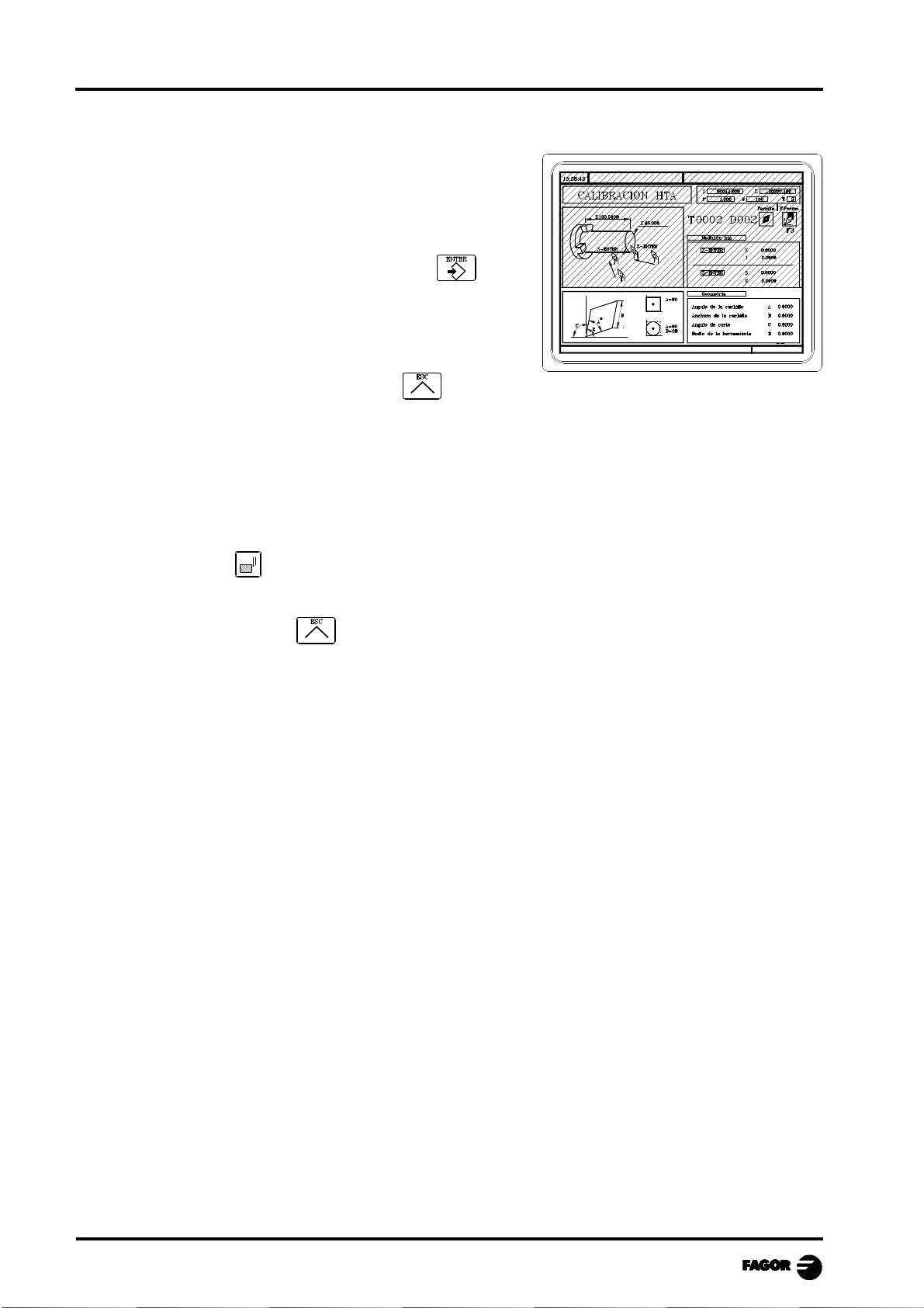
2. Operating in JOG mode
2.5 Tool control
2.5.2 Tool calibration
5.- Define the values for the tool geometry.
The window on the right contains the tool geometry
values and the window on the left contains a help
diagram.
To define one of these values, select the corresponding
field, key in the desired value and press
6.- To calibrate another tool, repeat steps 3, 4 and 5.
To quit the tool calibration mode, press
2.5.2.1 MODIFY VALUES DURING EXECUTION
TC work mode
It is possible to modify the tool values (dimensions and geometry) without interrupting program
execution.
To do this, press , the CNC will display the Tool Calibration screen with the data for the active
tool and it is possible to change its data or that of any other tool.
To quit this screen, press
Chapter 2 - page 20
Page 82

TC work mode
2. Operating in JOG mode
2.5 Tool control
2.5.3 Live Tool
2.5.3 LIVE TOOL
When a live tool is selected, the standard screen of the TC operating mode shows the following
information:
CHANGE POSITION
To select the rpm "S" of the live tool, take these steps:
1. Press to select the "T" field.
2. Press or to select the rpm "S" of the live tool.
3. Key in the value and press
The keys for the live tool are:
Live tool clockwise .................................................
Live tool counter-clockwise ...................................
Stop the live tool ......................................................
When the machine uses a live tool, the following considerations must be born in mind:
Set one of the general machine parameters P0 through P9 to "13"
The location code (shape) of the live tool must be "10", "20" or "30".
It is up to the PLC to manage the keys for the live tool.
Every time one of these keys is pressed, the CNC updates the corresponding register bit.
Bit 7 of Register 561 (B7 R561) indicates the status of the key.
Bit 3 of Register 562 (B3 R562) indicates the status of the key.
Bit 5 of the Register 562 (B5 R562) indicates the status of the key
Here is an example of the section of the PLC program in charge of managing the live tool:
( ) = CNCRD (TOOL, R101, M1)
Assigns the number of the active tool to register R101.
= CNCRD (TOF R101, R102, M1)
Assigns the location code (shape) of the active tool to register R102.
CPS R102 EQ 10 OR CPS R102 EQ 20 OR CPS R102 EQ 30 = M2
If the active tool is a live tool, (location code=10, 20 or 30), it activates mark M2.
Chapter 2 - page 21
Page 83

2. Operating in JOG mode
2.5 Tool control
2.5.3 Live Tool
TC work mode
CUSTOM AND (DFU B7R561 OR DFD M2) = CNCEX1 (M45 S0, M1)
If while the TC operating mode is selected (CUSTOM=1) ...
... the "stop live tool" key is pressed (DFU B7R561) or the live tool is de-selected
(DFD M2) .....
... the PLC "tells" the CNC to execute block "M45 S0" to stop the live tool.
CUSTOM AND M2 AND DFU B3R562 = CNCRD (LIVRPM, R117, M1) = CNCWR (R117,
GUP100, M1)= CNCEX1 (M45 SP100, M1)
If in TC mode (CUSTOM=1) a live tool is selected (M2) and the "live tool
clockwise" key is pressed, (DFU B3R562) ...
... the PLC reads in R117 the rpm selected for the live tool (LIVRPM) and it assigns
them to general parameter P100... It, then, "tells" the CNC to execute block "M45
SP100" (clockwise turning of the live tool at the selected rpm).
CUSTOM AND M2 AND DFU B5R562 = CNCRD (LIVRPM, R117, M1) = CNCWR (R117,
GUP100, M1= CNCEX1 (M45 S-P100, M1)
If in 8055 TC mode (CUSTOM=1) a live tool is selected (M2) and the "live tool
counter-clockwise" key is pressed (DFU B5R562) ...
... the PLC "tells" the CNC to execute block M45 S-P100 (counter-clockwise
turning of the live tool at the selected rpm).
Chapter 2 - page 22
Page 84

TC work mode
2. Operating in JOG mode
2.6 Spindle control
2.6 SPINDLE CONTROL
The standard TC working mode screen has a window for displaying information about the spindle.
Since the CNC allows operating with the spindle in RPM, at Constant Surface Speed or in the Spindle
Orientation mode, the information being displayed will be different for each mode.
CSS
(CSS) RPM without RPM with
spindle orientation spindle orientation
To change from one mode to another press
RANGE 1
Both on power-up of the CNC and after the key sequence the CNC selects the operating
mode as Revolutions / minute (RPM)
When working at Constant Surface Speed (CSS), the key is lit up.
Chapter 2 - page 23
Page 85

2. Operating in JOG mode
2.6 Spindle control
2.6.1 Spindle in rpm.
2.6.1 SPINDLE IN RPM
The CNC displays the following information:
1.- Actual spindle speed in rpm.
2.- Theoretical spindle speed in rpm.
To select any other speed press . The CNC will frame the present value.
Enter the new value and press . The CNC assumes said value and updates the actual speed
of the spindle.
TC work mode
3.- State of the spindle: turning clockwise, turning counter-clockwise or stopped.
To modify the state of the spindle press keys:
4.- % of the theoretical turning speed of the spindle that is being applied.
To modify this percentage (%) press keys:
5.- Maximum spindle speed in rpm.
To select any other speed press twice. The CNC will frame the present value.
Enter the new value and press . The CNC assumes said value and will not let the spindle
exceed this number of revolutions.
6.- Spindle range currently selected.
When having an automatic gear changer, this value cannot be modified.
When not having an automatic gear changer, press and then use the key to frame the
current value.
Enter the range number to be selected and press or
Note: When the machine does not have spindle ranges this message is superfluous. For this
reason, when text 28 of program 999997 is not defined, the CNC does not display this
message.
Chapter 2 - page 24
Page 86

TC work mode
2. Operating in JOG mode
2.6 Spindle control
2.6.2 Constant Surface Speed
2.6.2 CONSTANT SURFACE SPEED
In Constant surface speed mode the user sets the tangential speed that there must be at all times
between the tool tip and the part.
The spindle revolutions therefore depend on the position taken by the tool tip with respect to the
turning axis. If the tool tip moves away from the turning axis, the spindle revolutions thus go down,
and if it gets closer, they go up.
When Constant Surface Speed is selected the CNC displays the following information.
1.- Actual spindle speed in rpm.
2.- Theoretical constant surface speed. Defined in m/minute or in feet/minute.
To select any other speed press . The CNC will frame the present value.
Enter the new value and press . The CNC assumes this value and if the spindle is started
it will update the actual speed of the spindle (in rpm.)
3.- State of the spindle: turning clockwise, turning counter-clockwise or stopped.
To modify the state of the spindle press:
4.- % of the theoretical Constant Surface Speed being applied.
To modify this percentage (%) press :
5.- Maximum spindle speed in rpm.
To select any other speed press twice and the CNC will frame the present value.
Enter the new value and press . The CNC will assume this value.
6.- Spindle range currently selected.
When having an automatic gear changer, this value cannot be modified.
When not having an automatic gear changer, press and then use the key to frame the
current value.
Enter the range number to be selected and press or
Note: When the machine does not have spindle ranges this message is superfluous. For this
reason, when text 28 of program 999997 is not defined, the CNC does not display this
message.
Chapter 2 - page 25
Page 87

2. Operating in JOG mode
2.6 Spindle control
2.6.2.1Operating at Constant Surface Speed
TC work mode
2.6.2.1 OPERATING AT CONSTANT SURFACE SPEED (CSS)
When Constant Surface Speed operating mode is selected (CSS), the CNC assumes the spindle range
selected at present.
In this operating mode, when a new constant surface speed is selected, the following cases may arise:
a) The spindle is stopped
The CNC selects the new speed but does not apply this until the spindle moves.
b) The spindle is started
The CNC, depending on the position of the axis, calculates and makes the spindle turn at the
corresponding rpm. speed for the Constant Surface Speed to be as defined.
As the axes move, when working at Constant Surface Speed, the following cases may arise:
a) The spindle is started
The CNC moves the axes to the F programmed.
As the X axis is moved, the CNC makes the spindle speed (rpm.) match to maintain the constant
surface speed selected.
If the tool tip moves away from the turning axis the spindle revolutions therefore go down, and
if it gets nearer, they go up.
The CNC limits the spindle revolutions to the maximum speed set «SMAX».
b) The spindle is stopped but a spindle speed S is selected
The CNC calculates, in millimeters/minute, the feedrate corresponding to the last programmed
"S" and moves the axis.
For example, if «F 2.000» and «CSS 500»:
F (mm/min) = F (mm/min.) x S (rev/min) = 2 x 500 = 1000 mm/min
The axis moves at a feedrate of 1000 millimeters/minute
c) The spindle is stationary and there is no spindle speed S selected.
If feedrate F has value 0, the CNC moves the axes at fast feedrate.
If feedrate F has any other value, the axes will only be able to be moved if key is pressed
and the key for one axis. The CNC moves the axis at fast feedrate.
Chapter 2 - page 26
Page 88

TC work mode
2. Operation in JOG mode
2.6 Spindle Control
2.6.3 Spindle Orientation
2.6.3 SPINDLE ORIENTATION
When having spindle orientation (general machine parameter REFEED1 (P34) other than 0) the CNC
shows the following information:
1.- Actual spindle speed in rpm.
2.- Angular spindle position in degrees.
This data is displayed when working in Spindle Orientation mode. When switching to RPM
mode, only the actual spindle speed is shown (1).
3.- Theoretical spindle speed in rpm.
To select another speed, press The CNC will frame the current value.
Enter the new value and press . The CNC assumes this value and it updates the actual
spindle speed.
4.- Spindle status: turning clockwise, turning counter-clockwise or .
When working in Spindle Orientation mode, it always shows the symbol.
5.- % of the theoretical spindle speed being applied.
The CNC does not apply this factor when working in Spindle
Orientation mode. It only applies it when working in RPM mode.
To change this percentage (%) press:
6.- Maximum spindle rpm.
To select another speed, press twice. The CNC will frame the current value.
Enter the new value and press The CNC assumes this value and will not let the spindle
exceed these rpm.
7.- Selected spindle range.
To select another range when there is no automatic range changer, press and then use the
key to frame the current value.
Enter the range number to be selected and press or
When the machine does not have a range changer, this message is superfluous. That's why the
CNC does not show this message when text 28 of program 999997 is not defined.
8.- Angular spindle increment when operating in Spindle Orientation mode.
To select another value, press key three times. The CNC will frame the current value.
Key in the new value and press
Chapter 2 - page 27
Page 89

2. Operation in JOG mode
2.6 Spindle Control
2.6.3 Spindle Orientation
TC work mode
2.6.3.1 OPERATION WITH SPINDLE ORIENTATION
When having spindle orientation, the CNC uses the same screen as when operating in RPM mode.
RPM mode.
To select this mode, press one of these three keys. The screen will not show the angular position
of the spindle.
Spindle Orientation mode:
To select this operating mode, press the key for spindle orientation:
The spindle will stop (if it was turning), it then searches home and, finally, it turns to the angular
position indicated at the lower right-hand side of the screen (the top figure shows 20º ).
Every time the key for Spindle Orientation is pressed, the spindle position is incremented by that
amount (the top figure shows 20).
Chapter 2 - page 28
Page 90

TC work mode
2. Operating in JOG mode
2.7 Control of external devices
2.7 CONTROL OF EXTERNAL DEVICES
The CNC allows up to 6 external devices to be activated and deactivated from the keyboard. One of
these is the cooling fluid.
The activation and deactivation of the devices must be carried out by the machine manufacturer by
means of the PLC program.
The CNC will inform the PLC of the status of each one of the keys. The relevant Register bit will have
value 1 when the key is pressed and value 0 when this is not pressed.
The Register bit for each one of the keys is as follows:
The status of the light for each one of these keys must be controlled by the machine manufacturer
by means of the PLC program, with the TCLED* input variables shown in the figure being available
for this purpose.
Examples:
Control of the coolant: DFU B28R561 = CPL TCLED1
= CPL O33
Control of the tail-stock (O1). To activate or deactivate the tail-stock a number of conditions must
be satisfied such as spindle stopped, ....
DFU B30R561 AND (Remaining conditions) = CPL TCLED2
= CPL O34
Chapter 2 - page 29
Page 91

2. Operation in Jog mode
2.8 Handling ISO code
2.8 HANDLING ISO CODE
With the ISO key, it is possible to access the MDI mode or the ISO work mode.
To access the MDI mode, put the CNC in jog mode and then press
The CNC displays a window at the bottom of the standard (or special) screen
TC work mode
An ISO coded block may be edited in this window to be executed later on, like in MDI in the "T" mode.
To access the ISO mode, while working with operations or cycles, press once and while working
in JOG mode, press that key twice.
When accessing the ISO mode, a special screen is displayed where it is possible to edit up to 6
program blocks in ISO or in high level language.
Example: [ISO]
G95 G96 S120 M3
G0 Z100
G1 X30 F0.1
Once the desired block or blocks have been edited, press The upper right-hand side of the
screen will show the symbol
From this moment on, the blocks being edited may be simulated, executed or stored as any operation
or cycle.
Press to simulate it. Press to execute it.
It is possible to combine blocks edited in ISO code with standard or User machining cycles to make
up part-programs. The chapter on "Storing part-programs" describes how to edit them and operate
with them.
To store blocks edited in ISO code, press
Chapter 2 - page 30
Page 92

TC work mode
3. Operating with operations or cycles
3. OPERA TING WITH OPERATIONS OR CYCLES
The following CNC keys should be used to select the machining Operations or Cycles:
When pressing the CNC shows all the user cycles already defined by the machine manufacturer
by means of the application program: WGDRAW.
The user cycle is edited like any other standard cycle of the TC mode.
Once all the necessary data has been defined, the user can Simular or Execute the cycle like any
other standard cycle of the TC mode.
When pressing any other key, the CNC selects the corresponding standard machining cycle, changes
the screen and lights up the lamp of the key just pressed indicating that the cycle has been selected.
The machining operations or cycles that can be selected with each one of these keys are:
Positioning cycle Turning cycle
Facing cycle Taper cycle
Rounding cycle Threading cycle
Grooving cycle Drilling and tapping cycles
Profile Cycle
When the Machining Operation or Cycle involves several levels key has to be pressed to select
the cycle level required:
With this CNC, it is possible to combine ISO-coded blocks with standard and/or user-defined
machining operations to create part-programs as described in the chapter on "Part-program storage".
To deselect the cycle and return to the standard display, press the key corresponding to the selected
cycle (the one with the indicator lamp on) or
Note: the operations or cycles can modify global parameters 150 through 299 (both included).
Chapter 3 - page 1
Page 93

3. Operating with operations or cycles
GEAR
3.1 Operation edit mode
3.1. OPERATION EDIT MODE
After selecting the cycle edition mode the CNC displays a screen looking like this:
TURNING CYCLE
TC work mode
1.- Denomination of the Operation or Work cycle selected.
2.- Help graphics.
3.- Spindle Conditions for cycle execution.
4.- Present status of the machine. Coordinates and machining conditions.
5.- Data defining the geometry of the Machining Cycle.
6.- Machining conditions for the roughing operation.
7.- Machining conditions for the finishing operation.
The CNC will display an icon, a coordinate or one of the data items defining the operation or cycle
in highlighted print, to show that this item has been selected.
To select another icon, data item or coordinate, one can:
a) Use keys . The CNC will select the previous or next data item.
b) Press key or . The CNC will select the first data item for said axis. Pressing this key
again will select the following piece of data for said axis.
c) Press key or . The CNC selects the relevant roughing data. Pressing said key again
will select the relevant finishing data.
d) Press key . The CNC selects data item «S» for roughing. Pressing this key a second time
selects data item «S» for finishing, and pressing it again selects the data for spindle SMAX.
The coordinates for axis X are defined in operating units, radii or diameters.
Later on, in each one of the operations or cycles, the units in which the data associated with axis X
(safety distance, pass, excess stock, etc.) are displayed.
Chapter 3 - page 2
Page 94

TC work mode
3. Operating with operations or cycles
3.1 Operation edit mode
3.1.1 Definition of spindle conditions
3.1.1 DEFINITION OF SPINDLE CONDITIONS
Work mode (RPM) or (CSS)
RANGE RANGE
Move over the "RPM" or "CSS" icon. this can be done:
a) By using the keys
b) by pressing . The CNC selects this item directly.
After selecting the item, press or to change the work mode.
Spindle range
Move over this item, key in the desired value and press
Maximum spindle turning speed in rpm (S)
Move onto this item, type in the required value and press
Spindle turning direction
There are 2 ways to select the spindle turning direction:
a) Move onto this item and press to change the icon.
b) Start the spindle in the direction required by means of the JOG keys
The CNC starts the spindle and assumes said turning direction as spindle turning data for the
cycle.
Coolant
Place the cursor over this data and press to change the icon.
means turning the coolant on. The CNC outputs the M8 function to the PLC.
means turning the coolant off. The CNC outputs the M9 function to the PLC.
Once the operation or the cycle is completed or the part program it belongs to, the CNC outputs
the M9 function to the PLC.
Chapter 3 - page 3
Page 95

3. Operating with operations or cycles
3.1 Operation edit mode
3.1.2 Definition of machining conditions
TC work mode
3.1.2 DEFINITION OF MACHINING CONDITIONS
Some cycles maintain the same machining conditions during the whole execution process (positioning
cycle, drilling cycle ...)
Other cycles use machining cycles for roughing and other conditions for finishing ,(turning cycle,
rounding cycle, ...)
This section shows how all this data has to be defined.
Axis feedrate (F)
Move onto this item, key in the value required and press
Spindle turning speed (S)
Move onto this item, key in the value required and press
Tool for machining (T)
Move onto this item, key in the value required and press
The CNC updates the "D" offset and the adjacent icon, displaying the graphic representation for
the location code associated with the new tool.
Tool calibration may also be accessed to consult or change the data corresponding to the selected
tool. To do this, position over the "T" field and press
To exit the tool calibration mode and return to the cycle, press
Roughing Pass (?)
Move onto this item, key in the value required and press
Finishing Stock (?)
Move onto this item, key in the value required and press
The finishing stock is always defined in radii.
Machining direction
Some cycles allow the machining direction to be selected (turning direction or facing direction).
To do this, move onto this icon and press
The icon changes and the help graph is updated.
Chapter 3 - page 4
Turning direction Facing direction
Page 96

TC work mode
3.1.3 CYCLE LEVEL
All the cycles have several editing levels.
Each level has its own screen and the main window of the cycle indicates (with tabs) the available
levels and which one is currently selected.
3. Operating with operations or cycles
3.1 Operation edit mode
3.1.3 Cycle level
To change levels, use the key or the "Page up" and "Page down" keys to scroll up and down
through the different levels.
Chapter 3 - page 5
Page 97

3. Operating with operations or cycles
GEAR
GEAR
3.2 Simulating and executing the operation
3.2 SIMULATING AND EXECUTING THE CYCLE
There are ways to work with operations or cycles: Editing mode and Execution mode.
Editing mode Execution mode
To switch from Editing mode to Execution mode, press
TC work mode
To switch from the Execution mode to the Editing mode, press one of these keys:
An operation or cycle may be simulated in any of these modes. To do that, press
For further information, refer to the chapter on "Execution and Simulation".
To execute an operation or cycle, select the Execution mode and press
For further information, refer to the chapter on "Execution and Simulation".
3.2.1 BACKGR OUND EDITING OF CYCLES
It is possible to edit an operation or cycle while running a part-program (background editing).
The new operation edited may be stored as part of the part-program (other than the one being
executed).
No operation being edited in the background may be executed or simulated, or the current position
of the machine be assigned to a coordinate.
To make a tool inspection or change while background editing, proceed as follows:
Press => To interrupt the execution of the program and resume background editing.
Press => To quit background editing.
Press => To go into tool inspection.
When pressing [T] without quitting background editing, it select the "T" field of the operation or
canned cycle being edited.
Warning
Background editing is not possible while executing an independent operation or
cycle. It is only possible while executing a part-program.
Chapter 3 - page 6
Page 98

TC work mode
GEAR
GEAR
3.3 POSITIONING CYCLE
To select the Positioning cycle press
This cycle can be defined in two different ways
Level 1.
3. Operating with operations or cycles
3.3 Positioning cycle
The coordinates of the target point have to be defined
The way the positioning is to be done
The type of feedrate, fast or at the F stated
Level 2.
The coordinates of the target point have to be defined
The way the positioning is to be done
The type of feedrate, fast or at the F stated
The auxiliary functions to be executed before and after positioning
Coordinate (Xi, Zi)
To change levels, use the key or the "Page up" and "Page down" keys to scroll up and down
through the different levels.
Chapter 3 - page 7
Page 99

3. Operating with operations or cycles
3.3 Positioning cycle
3.3.1 Definition of data
3.3.1 DEFINITION OF DATA
Type of positioning
To select the type of positioning move onto this icon and press
The icon changes and the help graphics are updated.
Type of feedrate
Feedrate at te selected F In rapid traverse
TC work mode
To select the type of feedrate move onto this icon and press
Coordinates of the target point (X,Z)
The coordinates are defined one by one. After moving onto the coordinates for the axis required
for definition, one can:
a) Manually enter the value. Enter the value required and press
b) Assign the present position of the machine.
Move the axis, by means of the handwheel or the JOG keys, to the point required. The top
right-hand window shows the tool coordinate at all times.
Press for the data item selected to take on the value displayed in the top right-hand
window.
Press
The auxiliary functions “M” which will be executed before and after positioning
Auxiliary function “M” is the name given to the functions determined by the manufacturer which
allow the different machine devices to be governed.
There are auxiliary functions “M” for activating a program stop, for selecting the spindle turning
direction, for controlling the coolant, for controlling the spindle gearbox, etc..
The Programming manual states how these functions should be programmed and the Installation
manual explains how the system should be set to operate with them.
To define the auxiliary functions to be executed before and after positioning:
a) Move into the relevant window by means of the keys
b) Define the auxiliary functions required.
The functions will be executed in the same order as these are arranged on the list.
To erase a function, select this and press
Chapter 3 - page 8
To move around within the window use the keys
Page 100
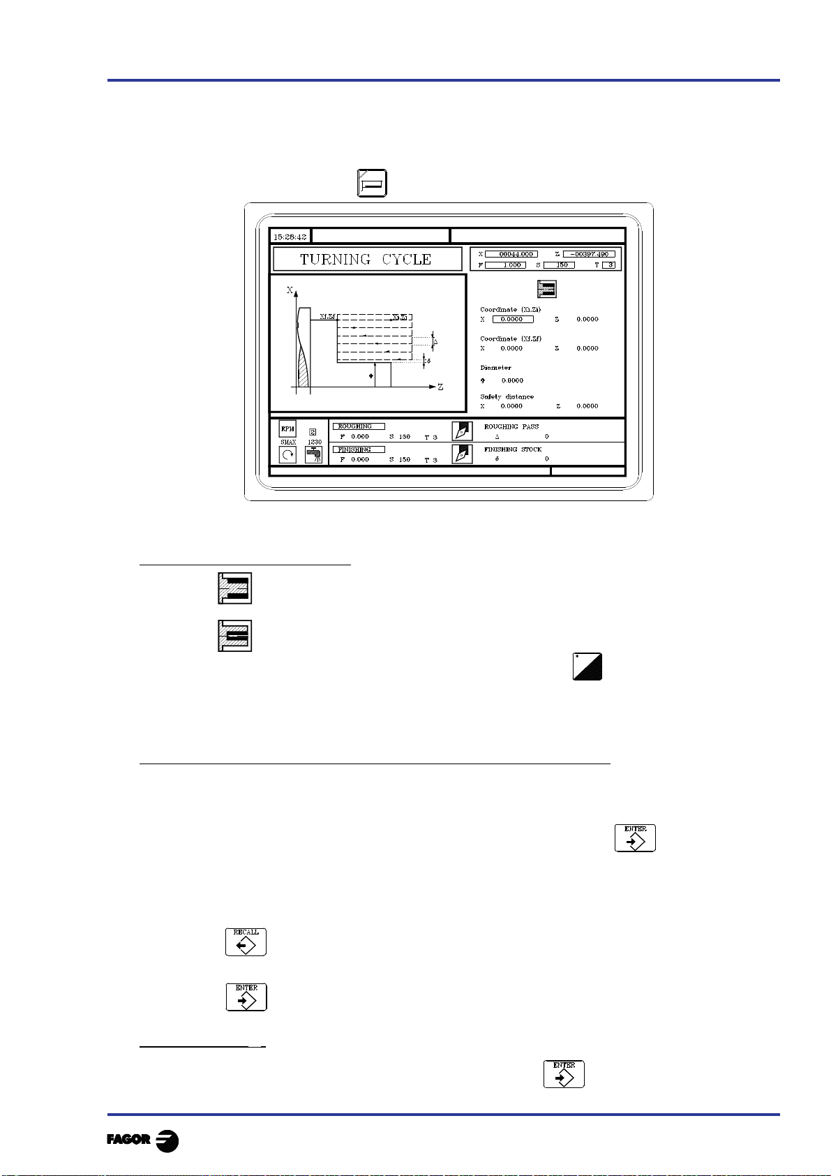
TC work mode
GEAR
3.4 TURNING CYCLE
To select the turning cycle press
3. Operating with operations or cycles
3.4 Turning cycle
3.4.1 Definition of geometry
3.4.1 DEFINITION OF GEOMETRY
Type of turning: internal or external
External turning
Internal turning
To modify the type of turning move onto this icon and press
Each time the turning type is changed the CNC modifies the icon and displays the relevant
geometrical help screen.
Coordinates of the starting point (Xi, Zi) and coordinates of the end point (Xf, Zf)
The coordinates are defined one by one. After moving onto the coordinates of the axis to be
defined, one can:
a) Manually enter the value. Key in the value required and press
b) Assign the present position of the machine.
Move the axis, by means of the handwheel or the JOG keys, to the point required. The top
right-hand window displays the tool coordinate at all times.
Press for the data item selected to take on the value displayed in the top right-hand
window.
Press
Final diameter (? )
Move onto this item, key in the required value and press
Chapter 3 - page 9
 Loading...