

fagor 8037 Operating Manual

CNC
8037 ·TC·
Operating manual
Ref. 1310
Soft: V01.4x

It is possible that CNC can execute more functions than those described in its
associated documentation; however, Fagor Automation does not guarantee the
validity of those applications. Therefore, except under the express permission
from Fagor Automation, any CNC application that is not described in the
documentation must be considered as "impossible". In any case, Fagor
Automation shall not be held responsible for any personal injuries or physical
All rights reserved. No part of this documentation may be transmitted,
transcribed, stored in a backup device or translated into another language
without Fagor Automation’s consent. Unauthorized copying or distributing of this
software is prohibited.
The information described in this manual may be subject to changes due to
technical modifications. Fagor Automation reserves the right to change the
contents of this manual without prior notice.
All the trade marks appearing in the manual belong to the corresponding owners.
The use of these marks by third parties for their own purpose could violate the
rights of the owners.
This product uses the following source code, subject to the terms of the GPL license. The applications busybox V0.60.2;
dosfstools V2.9; linux-ftpd V0.17; ppp V2.4.0; utelnet V0.1.1. The librarygrx V2.4.4. The linux kernel V2.4.4. The linux boot
ppcboot V1.1.3. If you would like to have a CD copy of this source code sent to you, send 10 Euros to Fagor Automation
for shipping and handling.
damage caused or suffered by the CNC if it is used in any way other than as
explained in the related documentation.
The content of this manual and its validity for the product described here has been
verified. Even so, involuntary errors are possible, hence no absolute match is
guaranteed. However, the contents of this document are regularly checked and
updated implementing the necessary corrections in a later edition. We appreciate
your suggestions for improvement.
The examples described in this manual are for learning purposes. Before using
them in industrial applications, they must be properly adapted making sure that
the safety regulations are fully met.

Operating manual
About the product ......................................................................................................................... 5
Declaration of conformity .............................................................................................................. 7
Version history .............................................................................................................................. 9
Safety conditions ........................................................................................................................ 11
Warranty terms ........................................................................................................................... 15
Material returning terms.............................................................................................................. 17
Additional remarks ...................................................................................................................... 19
Fagor documentation.................................................................................................................. 21
CHAPTER 1 GENERAL CONCEPTS
1.1 Keyboard........................................................................................................................ 23
1.2 General concepts........................................................................................................... 25
1.2.1 P999997 text program management.......................................................................... 27
1.3 Power-up........................................................................................................................ 28
1.4 Operating in T mode ...................................................................................................... 29
1.5 Video off......................................................................................................................... 30
1.6 Managing the CYCLE START key................................................................................. 31
INDEX
CHAPTER 2 OPERATING IN JOG MODE
2.1 Introduction .................................................................................................................... 34
2.1.1 Standard screen of the TC mode ............................................................................... 34
2.1.2 Description of the special screen of the TC mode ..................................................... 36
2.1.3 Selecting a program for simulation or execution ........................................................ 38
2.2 Axis control .................................................................................................................... 39
2.2.1 Work units .................................................................................................................. 39
2.2.2 Coordinate preset....................................................................................................... 40
2.2.3 Managing the axis feedrate (F) .................................................................................. 41
2.3 Home search..................................................................................................................42
2.4 Zero offset table ............................................................................................................. 43
2.5 Jog movement ............................................................................................................... 44
2.5.1 Moving an axis to a particular position (coordinate)................................................... 45
2.5.2 Incremental movement............................................................................................... 46
2.5.3 Continuous movement ............................................................................................... 47
2.5.4 Path-jog...................................................................................................................... 49
2.5.5 Movement with an electronic handwheel ................................................................... 51
2.5.6 Feed handwheel......................................................................................................... 52
2.5.7 Path-handwheel ......................................................................................................... 53
2.6 Tool control .................................................................................................................... 54
2.6.1 Tool change ............................................................................................................... 55
2.6.2 Variable tool change point.......................................................................................... 56
2.7 Tool calibration............................................................................................................... 57
2.7.1 Define the tool in the tool table................................................................................... 58
2.7.2 Manual tool calibration ............................................................................................... 61
2.8 Spindle control ............................................................................................................... 63
2.8.1 Spindle in rpm ............................................................................................................ 64
2.8.2 Spindle in constant surface speed mode ................................................................... 66
2.8.3 Spindle orientation ..................................................................................................... 68
2.9 ISO management........................................................................................................... 70
CHAPTER 3 WORKING WITH OPERATIONS OR CYCLES
3.1 Operation editing mode.................................................................................................. 75
3.1.1 Definition of spindle conditions................................................................................... 76
3.1.2 Definition of machining conditions.............................................................................. 77
3.1.3 Cycle level.................................................................................................................. 79
3.2 Simulating and executing the operation......................................................................... 80
3.2.1 Background cycle editing ........................................................................................... 81
3.3 Positioning cycle ............................................................................................................82
3.3.1 Definition of data ........................................................................................................ 83
3.4 Turning cycle.................................................................................................................. 84
3.4.1 Definition of data ........................................................................................................ 85
3.4.2 Basic operation .......................................................................................................... 87
CNC 8037
SOFT: V01.4X
·3·

Operating manual
3.5 Facing cycle................................................................................................................... 89
3.5.1 Definition of data ........................................................................................................ 90
3.5.2 Basic operation .......................................................................................................... 91
3.6 Taper turning cycle ........................................................................................................ 93
3.6.1 Definition of data ........................................................................................................ 94
3.6.2 Basic operation .......................................................................................................... 97
3.7 Rounding cycle .............................................................................................................. 99
3.7.1 Definition of geometry .............................................................................................. 100
3.7.2 Basic operation ........................................................................................................ 103
3.8 Threading cycle ........................................................................................................... 105
3.8.1 Definition of geometry .............................................................................................. 107
3.8.2 Standard threads ..................................................................................................... 111
3.8.3 Basic operation. Longitudinal threadcutting ............................................................. 118
3.8.4 Basic operation. Taper thread.................................................................................. 119
3.8.5 Basic operation. Face tapping ................................................................................. 120
3.9 Grooving cycle ............................................................................................................. 121
3.9.1 Calibration of the grooving tool ................................................................................ 123
3.9.2 Definition of geometry .............................................................................................. 124
3.9.3 Basic operation. Slot milling..................................................................................... 128
3.9.4 Basic operation. Cut-off ........................................................................................... 130
3.10 Drilling and tapping cycles ........................................................................................... 131
3.10.1 Definition of geometry .............................................................................................. 132
3.10.2 Drilling cycle. Basic operation .................................................................................. 133
3.10.3 Tapping cycle. Basic operation ................................................................................ 134
3.11 Profiling cycle............................................................................................................... 135
3.11.1 Level 1. Profile definition.......................................................................................... 136
3.11.2 Level 2. Profile definition.......................................................................................... 138
3.11.3 Level 2. Optimizing of the machining of a profile ..................................................... 139
3.11.4 Definition of geometry levels 1 and 2. ZX profile ..................................................... 140
3.11.5 Basic operation at levels 1 and 2. ZX profile............................................................ 143
3.11.6 Example. Level 1 ..................................................................................................... 144
3.11.7 Examples. Level 2.................................................................................................... 145
CNC 8037
SOFT: V01.4X
CHAPTER 4 OPERATING IN ISO MODE
4.1 Editing blocks in ISO mode.......................................................................................... 156
4.2 Programming assistance ............................................................................................. 157
4.2.1 Zero offsets and presets .......................................................................................... 157
4.2.2 Work zones .............................................................................................................. 158
4.2.3 Place labels and repetitions from label to label........................................................ 159
4.2.4 Mirror image............................................................................................................. 160
4.2.5 Scaling factor ........................................................................................................... 161
CHAPTER 5 SAVING PROGRAMS
5.1 List of saved programs ................................................................................................ 164
5.2 See the contents of a program .................................................................................... 165
5.2.1 Seeing one of the operations in detail...................................................................... 166
5.3 Edit a new part-program .............................................................................................. 167
5.4 Saving an ISO block or a cycle.................................................................................... 168
5.5 Delete a new part program .......................................................................................... 169
5.6 Copying a part-program into another one .................................................................... 170
5.7 Modify a part-program ................................................................................................. 171
5.7.1 Delete an operation.................................................................................................. 172
5.7.2 Add or insert a new operation .................................................................................. 173
5.7.3 Move an operation to another position..................................................................... 174
5.7.4 Modify an existing operation .................................................................................... 175
5.8 Managing programs using the explorer ....................................................................... 176
CHAPTER 6 EXECUTION AND SIMULATION
6.1 Simulating or executing an operation or cycle ............................................................. 178
6.2 Simulating or executing a part-program....................................................................... 179
6.2.1 Simulating or executing a portion of a part-program ................................................ 180
6.3 Simulating or executing an operation that has been saved ......................................... 181
6.4 Execution mode ........................................................................................................... 182
6.4.1 Tool inspection......................................................................................................... 183
6.5 Graphic representation ................................................................................................ 184
·4·

ABOUT THE PRODUCT
BASIC CHARACTERISTICS
Monitor 7.5" Color LCD
Block processing time 7 ms
Look-ahead 75 blocks
RAM memory 1 Mb
Flash memory 128 MB
PLC cycle time 3 ms / 1000 instructions
Minimum position loop 4 ms
USB Standard
RS-232 serial line Standard
DNC ( via RS232 ) Standard
Ethernet Option
5 V or 24 V probe inputs 2
Local digital inputs and outputs. 16 I / 8 O
40 I / 24 O
56 I / 32 O
Feedback inputs for the axes and spindle 4 TTL / 1Vpp inputs
Feedback inputs for handwheels 2 TTL inputs
Analog outputs 4 for axes and spindle
CAN servo drive system for Fagor servo drive connection. Option
Remote CAN modules, for digital I/O expansion (RIO). Option
Before start-up, verify that the machine that integrates this CNC meets the 89/392/CEE Directive.
CNC 8037
·5·

About the product
SOFTWARE OPTIONS
Model
M T TC
Number of axes 3 2 2
Number of spindles 1 1 1
Electronic threading Standard Standard Standard
Tool magazine management: Standard Standard Standard
Machining canned cycles Standard Standard Standard
Multiple machining Standard ----- -----
Rigid tapping Standard Standard Standard
DNC Standard Standard Standard
Tool radius compensation Standard Standard Standard
Retracing Standard ----- -----
Jerk control Standard Standard Standard
Feed forward Standard Standard Standard
Oscilloscope function (Setup assistance) Standard Standard Standard
Roundness test (Setup assistance) Standard Standard Standard
CNC 8037
·6·
DECLARATION OF CONFORMITY
The manufacturer:
Fagor Automation S. Coop.
Barrio de San Andrés Nº 19, C.P. 20500, Mondragón -Guipúzcoa- (SPAIN).
Declares:
Under their responsibility that the product:
8037 CNC
Consisting of the following modules and accessories:
8037-M, 8037-T, 8037-TC
Remote modules RIO
ETHERNET, ETHERNET-CAN-CAN AXES, ETHERNET-CAN AXES
Note.
Some additional characters may follow the references mentioned above. They all comply with the directives
listed. However, check that that's the case by checking the label of the unit itself.
Referred to by this declaration with following directives:
Low voltage regulations.
EN 60204-1: 2006 Electrical equipment on machines — Part 1. General requirements.
Regulation on electromagnetic compatibility.
EN 61131-2: 2007 PLC — Part 2. Requirements and equipment tests.
As instructed by the European Community Directives 2006/95/EEC on Low Voltage and
2004/108/EC on Electromagnetic Compatibility and its updates.
In Mondragón, March 14th, 2012
CNC 8037
·7·


VERSION HISTORY
Here is a list of the features added in each software version and the manuals that describe them.
The version history uses the following abbreviations:
INST Installation manual
PRG Programming manual
OPT Operating manual
OPT-TC Operating manual for the TC option.
Software V01.42 March 2012
First version.
CNC 8037
·9·

Version history
CNC 8037
·10·
SAFETY CONDITIONS
Read the following safety measures in order to prevent harming people or damage to this product and those
products connected to it.
This unit may only be repaired by authorized personnel at Fagor Automation.
Fagor Automation shall not be held responsible of any physical damage or defective unit resulting from not
complying with these basic safety regulations.
PRECAUTIONS AGAINST PERSONAL DAMAGE
• Interconnection of modules.
Use the connection cables provided with the unit.
• Use proper Mains AC power cables
To avoid risks, use only the Mains AC cables recommended for this unit.
• Avoid electrical overloads.
In order to avoid electrical discharges and fire hazards, do not apply electrical voltage outside the range
selected on the rear panel of the central unit.
• Ground connection.
In order to avoid electrical discharges, connect the ground terminals of all the modules to the main
ground terminal. Before connecting the inputs and outputs of this unit, make sure that all the grounding
connections are properly made.
• Before powering the unit up, make sure that it is connected to ground.
In order to avoid electrical discharges, make sure that all the grounding connections are properly made.
• Do not work in humid environments.
In order to avoid electrical discharges, always work under 90% of relative humidity (non-condensing)
and 45 ºC (113º F).
• Do not work in explosive environments.
In order to avoid risks or damages, do no work in explosive environments.
CNC 8037
·11·

CNC 8037
• Working environment.
This unit is ready to be used in industrial environments complying with the directives and regulations
effective in the European Community.
Fagor Automation shall not be held responsible for any damage suffered or caused when installed in
other environments (residential or homes).
• Install this unit in the proper place.
It is recommended, whenever possible, to install the CNC away from coolants, chemical product, blows,
etc. that could damage it.
This unit complies with the European directives on electromagnetic compatibility. Nevertheless, it is
recommended to keep it away from sources of electromagnetic disturbance such as:
Powerful loads connected to the same AC power line as this equipment.
Safety conditions
Nearby portable transmitters (Radio-telephones, Ham radio transmitters).
Nearby radio/TV transmitters.
Nearby arc welding machines.
Nearby High Voltage power lines.
Etc.
•Enclosures.
The manufacturer is responsible of assuring that the enclosure involving the equipment meets all the
currently effective directives of the European Community.
• Avoid disturbances coming from the machine tool.
The machine-tool must have all the interference generating elements (relay coils, contactors, motors,
etc.) uncoupled.
DC relay coils. Diode type 1N4000.
AC relay coils. RC connected as close to the coils as possible with approximate values of R=220
AC motors. RC connected between phases, with values of R=300 / 6 W y C=0,47 µF / 600 V.
• Use the proper power supply.
Use an external regulated 24 Vdc power supply for the inputs and outputs.
• Grounding of the power supply.
The zero volt point of the external power supply must be connected to the main ground point of the
machine.
• Analog inputs and outputs connection.
It is recommended to connect them using shielded cables and connecting their shields (mesh) to the
corresponding pin.
• Ambient conditions.
The working temperature must be between +5 ºC and +40 ºC (41ºF and 104º F)
The storage temperature must be between -25 ºC and +70 ºC. (-13 ºF and 158 ºF)
• Central unit enclosure (8037 CNC).
Make sure that the needed gap is kept between the central unit and each wall of the enclosure. Use
a DC fan to improve enclosure ventilation.
• Power switch.
This power switch must be mounted in such a way that it is easily accessed and at a distance between
0.7 meters (27.5 inches) and 1.7 meters (5.5ft) off the floor.
PRECAUTIONS AGAINST PRODUCT DAMAGE
1 W y C=0,2 µF / 600 V.
·12·
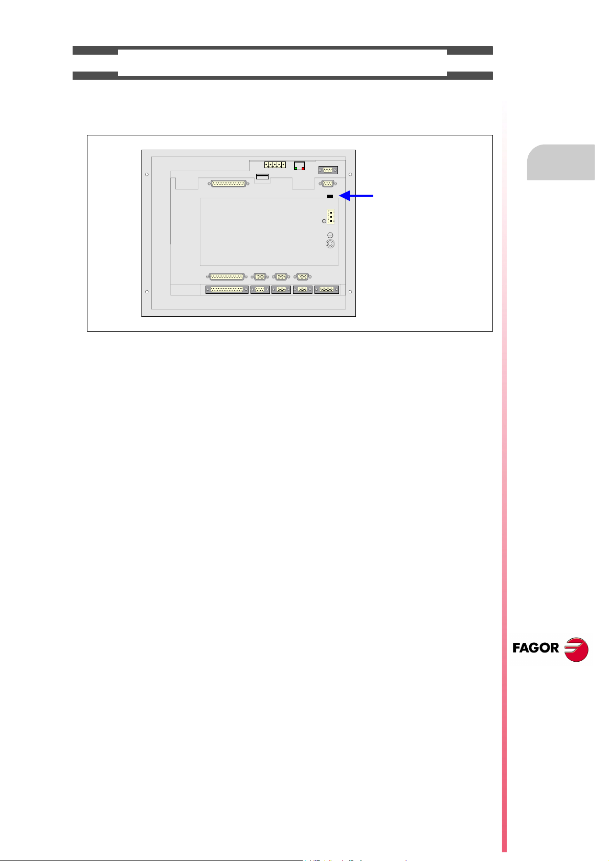
PROTECTIONS OF THE UNIT ITSELF (8037)
FUSE
X7
X1
X8
X9
X2
X10
X3
X11X4X12
X5
X6
+24V
0V
• Central Unit.
It has a 4 A 250V external fast fuse (F).
• Inputs-Outputs.
All the digital inputs and outputs have galvanic isolation via optocouplers between the CNC circuitry
and the outside.
Safety conditions
CNC 8037
·13·
PRECAUTIONS DURING REPAIR
i
Do not get into the inside of the unit. Only personnel authorized by Fagor Automation may manipulate
the inside of this unit.
Do not handle the connectors with the unit connected to main AC power. Before manipulating the
connectors (inputs/outputs, feedback, etc.) make sure that the unit is not connected to AC power.
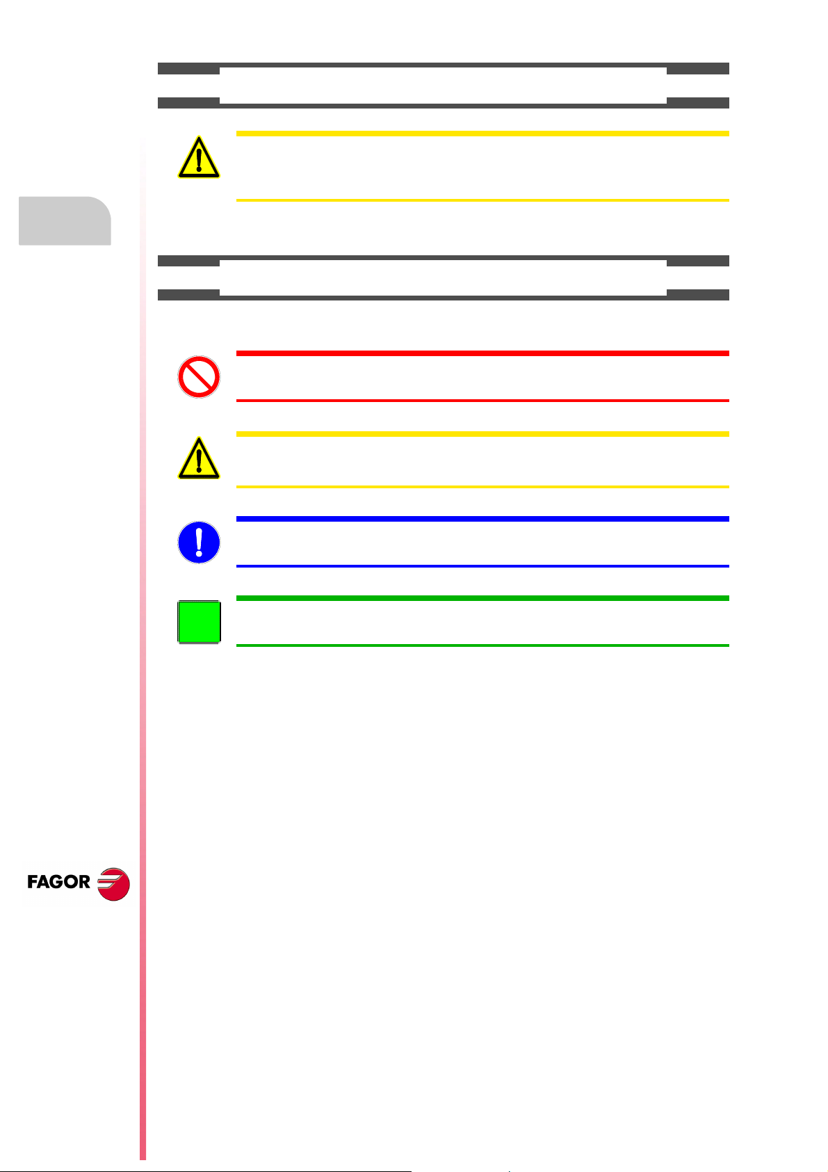
SAFETY SYMBOLS
Safety conditions
• Symbols which may appear on the manual.
Symbol for danger or prohibition.
It indicates actions or operations that may cause damage to people or to units.
Warning symbol.
It indicates situations that may be caused by certain operations and the actions to be taken to prevent
them.
Obligation symbol.
It indicates actions and operations that must be carried out.
Information symbol.
It indicates notes, warnings and advises.
CNC 8037
·14·

WARRANTY TERMS
INITIAL WARRANTY
All products manufactured or marketed by FAGOR carry a 12-month warranty for the end user which could
be controlled by the our service network by means of the warranty control system established by FAGOR
for this purpose.
In order to prevent the possibility of having the time period from the time a product leaves our warehouse
until the end user actually receives it run against this 12-month warranty, FAGOR has set up a warranty
control system based on having the manufacturer or agent inform FAGOR of the destination, identification
and on-machine installation date, by filling out the document accompanying each FAGOR product in the
warranty envelope. This system, besides assuring a full year of warranty to the end user, enables our service
network to know about FAGOR equipment coming from other countries into their area of responsibility.
The warranty starting date will be the one appearing as the installation date on the above mentioned
document. FAGOR offers the manufacturer or agent 12 months to sell and install the product. This means
that the warranty starting date may be up to one year after the product has left our warehouse so long as
the warranty control sheet has been sent back to us. This translates into the extension of warranty period
to two years since the product left our warehouse. If this sheet has not been sent to us, the warranty period
ends 15 months from when the product left our warehouse.
This warranty covers all costs of material and labour involved in repairs at FAGOR carried out to correct
malfunctions in the equipment. FAGOR undertakes to repair or replace their products within the period from
the moment manufacture begins until 8 years after the date on which it disappears from the catalog.
FAGOR has exclusive competence in deciding whether the repair enters within the term defined as the
warranty period.
EXCLUDING CLAUSES
Repairs will be carried out on our premises. Therefore, all expenses incurred as a result of trips made by
technical personnel to carry out equipment repairs, despite these being within the above-mentioned period
of warranty, are not covered by the warranty.
Said warranty will be applied whenever the equipment has been installed in accordance with instructions,
has not be mistreated, has not been damaged by accident or by negligence and has not been tampered
with by personnel not authorized by FAGOR. If, once servicing or repairs have been made, the cause of
the malfunction cannot be attributed to said elements, the customer is obliged to cover the expenses
incurred, in accordance with the tariffs in force.
Other warranties, implicit or explicit, are not covered and FAGOR AUTOMATION cannot be held responsible
for other damages which may occur.
CNC 8037
·15·
WARRANTY ON REPAIRS
In a similar way to the initial warranty, FAGOR offers a warranty on standard repairs according to the
following conditions:
PERIOD
CONCEPT
EXCLUDING CLAUSES
When the customer does not choose the standard repair and just the faulty material has been replaced,
Warranty terms
the warranty will cover just the replaced parts or components within 12 months.
For sold parts the warranty is 12 moths length.
The SERVICE CONTRACT is available for the distributor or manufacturer who buys and installs our CNC
systems.
12 months.
Covers parts and labor for repairs (or replacements) at the network's own
facilities.
The same as those applied regarding the chapter on initial warranty.
If the repair is carried out within the warranty period, the warranty extension
has no effect.
MAINTENANCE CONTRACTS
CNC 8037
·16·

MATERIAL RETURNING TERMS
When sending the central nit or the remote modules, pack them in its original package and packaging
material. If the original packaging material is not available, pack it as follows:
1. Get a cardboard box whose three inside dimensions are at least 15 cm (6 inches) larger than those
of the unit. The cardboard being used to make the box must have a resistance of 170 kg. (375 pounds).
2. Attach a label indicating the owner of the unit, person to contact, type of unit and serial number.
3. In case of failure, also indicate the symptom and a short description.
4. Wrap the unit in a polyethylene roll or similar material to protect it.
5. When sending the central unit, protect especially the screen.
6. Pad the unit inside the cardboard box with polyurethane foam on all sides.
7. Seal the cardboard box with packing tape or industrial staples.
CNC 8037
·17·

Material returning terms
CNC 8037
·18·

ADDITIONAL REMARKS
Mount the CNC away from coolants, chemical products, blows, etc. which could damage it. Before turning
the unit on, verify that the ground connections have been properly made.
In case of a malfunction or failure, disconnect it and call the technical service. Do not get into the inside
of the unit.
CNC 8037
·19·

Additional remarks
CNC 8037
·20·

FAGOR DOCUMENTATION
OEM manual
It is directed to the machine builder or person in charge of installing and starting-up the CNC.
USER-M manual
Directed to the end user.
It describes how to operate and program in M mode.
USER-T manual
Directed to the end user.
It describes how to operate and program in T mode.
TC Manual
Directed to the end user.
It describes how to operate and program in TC mode.
It contains a self-teaching manual.
CNC 8037
·21·

Fagor documentation
CNC 8037
·22·

GENERAL CONCEPTS
F1 F2 F3 F4 F5 F6 F7
FAGOR
PCALL
ISO
ZERO
HELP
i
MAIN
MENU
ESC RECALL ENTER RESETEDIT SIMUL EXEC
A B C D E F
LKJIHG
M N Ñ O P Q
WVUTSR
X Y Z
SP
\
CAPS
@
SHIFT
_
INS
CLEAR
=
7(8
)
$
9
/
%
4[5]6
&
1!2"3
·
*
?
+
>-<
0
;
:
.
%+
%-
SINGLE
CSS
m / min
SPINDLE
FEED
%
JOG
2
10
20
40
50
100
110
120
10
1
0
4
30
60
70
80
90
100
100
10
1
F1 F2 F3 F4 F5 F6 F7
FAGOR
PCALL
ISO
ZERO
HELP
i
MAIN
MENU
ESC RECALL ENTER RESETEDIT SIM UL EXEC
A B C D E F
LKJIHG
M N Ñ O P Q
WVUTSR
X Y Z SP
\
CAPS
@
SHIFT
_
INS
CLEAR
=
7(8
)
$
9
/
%
4[5]6
&
1!2"3
·*?
+
>-<
0
;
:
.
%+
%-
SINGLE
CSS
m / min
SPINDLE
FEED
%
JOG
2
10
20
40
50
100
110
120
10
1
0
4
30
60
70
80
90
100
100
10
1
7
(
SHIFT
7
(
F1 F2 F3 F4 F5 F6 F7
FAGOR
PCALL
ISO
ZERO
HELP
i
MAIN
MENU
ESC RECALL ENTER RESETEDIT SIMUL EXEC
A B C D E F
LKJIHG
M N Ñ O P Q
WVUTSR
X Y Z
SP
\
CAPS
@
SHIFT
_
INS
CLEAR
=
7(8
)
$
9
/
%
4[5]6
&
1!2"3
·*?
+
>-<
0
;
:
.
%+
%-
SINGLE
CSS
m / min
SPINDLE
FEED
%
JOG
2
10
20
40
50
100
110
120
10
1
0
4
30
60
70
80
90
100
100
10
1
1.1 Keyboard
1
Alphanumeric keyboard and command keys
Select the 7 character.
Select the ( character.
Specific keys of the TC model
These keys may be used for:
• Selecting and defining the machining operations.
• Selecting the spindle work mode.
• Selecting the single block or automatic execution Mode.
CNC 8037
·TC· OPTION
SOFT: V01.4X
·23·

1.
F1 F2 F3 F4 F5 F6 F7
FAGOR
PCALL
ISO
ZERO
HELP
i
MAIN
MENU
ESC RECALL ENTER RESETEDIT SIMUL EXEC
A B C D E F
LKJIHG
M N Ñ O P Q
WVUTSR
X Y Z
SP
\
CAPS
@
SHIFT
_
INS
CLEAR
=
7(8
)
$
9
/
%
4[5]6
&
1!2"3
·*?
+
>-<
0
;
:
.
%+
%-
SINGLE
CSS
m / min
SPINDLE
FEED
%
JOG
2
10
20
40
50
100
110
120
10
1
0
4
30
60
70
80
90
100
100
10
1
Operating manual
JOG keys
These keys may be used for:
• Moving the axes of the machine.
• Governing the spindle.
• Modifying the feedrate of the axes and the spindle speed.
• Starting and stopping the execution.
Keyboard
GENERAL CONCEPTS
CNC 8037
·TC· OPTION
SOFT: V01.4X
·24·

Operating manual
1.2 General concepts
It offers all the features of the T model plus those specific of the TC mode. For example, the CNC
setup must be done in T mode.
In TC work mode, programs P900000 through P999999 are reserved for the CNC itself; in other
words, the user cannot use them as part-programs.
On the other hand, in order to work in TC mode, the CNC must have programs P999997 and
P999998 stored in its memory. Both programs are related to the software version and, consequently,
are not supplied by Fagor Automation. Whenever the CNC detects a new software version , it updates
these programs automatically and, for safety, it makes a copy of the old ones in the KeyCF.
Likewise, subroutines 0000 through 8999 are free to use and subroutines 9000 through 9999 are
reserved for the CNC.
Programs P999997 and P999998 are associated with the software version. Fagor Automation shall
not be held responsible of the CNC's performance if programs P999997 and P999998 have been
deleted from memory or do not match the software version.
1.
General concepts
Subroutines reserved for the CNC
Some of the subroutines reserved for the CNC have the following meaning:
9998 Subroutine that the CNC will execute at the beginning of each part-program.
9999 Subroutine that the CNC will execute at the end of each part-program.
Every time a new part-program is edited, the CNC inserts a call to the relevant
subroutine at the beginning and at the end of the program.
Both subroutines must be defined by the machine manufacturer, even when no operation is to be
carried out at the beginning and at the end of the part-program. If they are not defined, the CNC
will issue an error message when trying to execute a part-program.
Example of how to define subroutine 9998.
( SUB 9998) ; Definition of subroutine 9998.
··· ; Program blocks defined by the OEM.
(RET) ; End of subroutine.
OEM (manufacturer's) parameters
OEM parameters and subroutines with OEM parameters can only be used in OEM programs; those
defined with the [O] attribute. Modifying one of these parameters in the tables requires an OEM
password.
GENERAL CONCEPTS
When using OEM parameters in the configuration programs, this program must have the [O]
attribute; otherwise, the CNC will issue an error when editing the user cycles that refer to OEM
parameters in write mode.
CNC 8037
·TC· OPTION
SOFT: V01.4X
·25·
1.
i
General concepts
GENERAL CONCEPTS
Operating manual
Programs reserved for the CNC
Some of the programs reserved for the CNC have the following meaning:
P999998
It is a program of subroutines that the CNC uses to interpret the programs edited in TC format and
execute them later on.
This program must not be modified. If this program is modified or deleted, Fagor Automation will not
be held responsible of the CNC's performance.
If the manufacturer needs to create his own subroutines (for home search, tool change, etc.), as well
as subroutines 9998 and 9999, they must be included in another program, for example P899999.
P999997
It is a text program that contains:
• The sentences and texts that will be displayed on the various screens of the TC mode.
• The help texts for the icons, in the work cycles, that are shown on the lower left side of the screen.
• The messages (MSG) and errors (ERR) that may come up at the TC model.
All the texts, messages and errors that may be translated into the desired language.
When modifying program 999997, it is recommended to make a backup copy of it because the CNC
replaces that program when selecting another language or updating the software version.
Considerations about the texts
The format of a line is as follows:
;Text number - explanatory comment (not displayed) - $Text to be displayed
All the program lines must begin with the ";" character and the text to be displayed must be preceded
by the "$" symbol. If a line begins with ";;", the CNC assumes that the whole line is a program
comment.
Examples:
;44 $M/MIN Is message 44 and displays the text "M/MIN"
;;General text The CNC treats it as a comment
;;44 Feedrate $M/MIN The CNC treats it as a comment
;44 Feedrate $M/MIN Is message 44 whose hidden explanatory comment is
"Feedrate" and displays the text "M/MIN"
Considerations about the messages
The format must be respected. Only the text after SAVEMSG may be translated:
Example:
Original message: N9500(MSG"SAVEMSG: TURNING CYCLE")
Translated message: N9500(MSG"SAVEMSG: ZILINDRAKETA ZIKLOA")
CNC 8037
·TC· OPTION
SOFT: V01.4X
Considerations about the errors
The format must be respected. Only the text between quote marks ("text") may be translated.
Example:
Original text: N9000(ERROR"Cycle without roughing")
Translated text: N9000(ERROR"Arbastatu gabeko zikloa")
P998000 ··· P998999
They are the profiles defined by the user with the profile editor. In the TC mode, the user defines
them with 3 digits (from 0 to 999) and the CNC saves them internally as P998xxx.
·26·

Operating manual
1.2.1 P999997 text program management
On power up, the CNC copies the texts of program P999997 into the system memory.
• It checks if program P999997 is in user memory, if not, it looks in the KeyCF and if it is not there
either, it assumes the default ones and copies them into program P999997 of the user memory.
• When selecting mainland Chinese, it ignores program P999997 and it always assumes the
default ones.
If when switching from T mode to TC mode, it cannot find program P999997 because it has been
deleted, it is initialized like on power-up.
When modifying the texts of program P999997, turn the CNC off and back on so it assumes the
new texts.
The CNC carries out the following operations when changing the language, the software version
and when adding TC conversational modes (new software features):
• It copies, for safety, the texts that were being used into KeyCF as program P999993.
• It deletes the program P999997 that may be in the KeyCF.
• It assumes the new texts that are provided by default and copies them into program P999997
of the user memory.
To change the texts, after modifying program P999997, turn the CNC off and back on so it assumes
the new texts.
1.
General concepts
GENERAL CONCEPTS
CNC 8037
·TC· OPTION
SOFT: V01.4X
·27·

1.
SHIFT
RESET
15:28:42 SBK P000002 IN POSITION
X
Z
S
00044.000
-00443.331
0
REFERENCE ZERO X 0000.000
REFERENCE ZERO Z 0000.000
F 0100.000
% 080
T 02
S 0100
D 12
CHANGE POSITION
X 25.000 Z 85.000
% 115
SMAX 1000 RANGE 1
020.0000
ESC
SHIFT
Operating manual
1.3 Power-up
On power-up and after the keystroke sequence [SHIFT] [RESET], the CNC shows
"page 0" defined by the manufacturer; if there is no "page 0", it shows the standard
screen of the work mode. Press any key to access the work mode.
The standard screen of the TC mode is the following:
Power-up
GENERAL CONCEPTS
CNC 8037
There are two work modes; TC mode and T mode. Press the key sequence
[SHIFT] [ESC] to toggle from one mode to the other.
The CNC setup must be done in T mode.
Likewise, some errors must be eliminated in T mode.
·TC· OPTION
SOFT: V01.4X
·28·

Operating manual
ESC
SHIFT
F1 F2 F3 F4 F5 F6 F7
FAGOR
PCALL
ISO
ZERO
HELP
i
MAIN
MENU
ESC RECALL ENTER RESETEDIT SIMUL EXEC
A B C D E F
LKJIHG
M N Ñ O P Q
WVUTSR
X Y Z SP
\
CAPS
@
SHIFT
_
INS
CLEAR
=
7(8
)
$
9
/
%
4[5]6
&
1!2"3
·
*
?
+
>-<
0
;
:
.
%+
%-
SINGLE
CSS
m / min
SPINDLE
FEED
%
JOG
2
10
20
40
50
100
110
120
10
1
0
4
30
60
70
80
90
100
100
10
1
F1 F2 F3 F4 F5
F6 F7
1.4 Operating in T mode
There are two work modes; TC mode and T mode. Press the key sequence
[SHIFT] [ESC] to toggle from one mode to the other.
The keyboard is designed for also working in T mode. In T mode, use the alphanumeric keyboard
and softkeys F1 through F7.
Alphanumeric keyboard:
Softkeys F1 to F7 are:
1.
Operating in T mode
GENERAL CONCEPTS
CNC 8037
·TC· OPTION
SOFT: V01.4X
·29·

1.
CLEAR
SHIFT
Operating manual
1.5 Video off
The keystroke sequence [SHIFT] [CLEAR] clears the CRT screen (it goes blank).
Press any key to restore the image.
Also, any message (PLC, program, etc.) restores the CNC image.
Video off
GENERAL CONCEPTS
CNC 8037
·TC· OPTION
SOFT: V01.4X
·30·
 Loading...