


CNC
8037 ·T·
Programming manual
Ref. 1310
Soft: V01.4x

It is possible that CNC can execute more functions than those described in its
associated documentation; however, Fagor Automation does not guarantee the
validity of those applications. Therefore, except under the express permission
from Fagor Automation, any CNC application that is not described in the
documentation must be considered as "impossible". In any case, Fagor
Automation shall not be held responsible for any personal injuries or physical
All rights reserved. No part of this documentation may be transmitted,
transcribed, stored in a backup device or translated into another language
without Fagor Automation’s consent. Unauthorized copying or distributing of this
software is prohibited.
The information described in this manual may be subject to changes due to
technical modifications. Fagor Automation reserves the right to change the
contents of this manual without prior notice.
All the trade marks appearing in the manual belong to the corresponding owners.
The use of these marks by third parties for their own purpose could violate the
rights of the owners.
This product uses the following source code, subject to the terms of the GPL license. The applications busybox V0.60.2;
dosfstools V2.9; linux-ftpd V0.17; ppp V2.4.0; utelnet V0.1.1. The librarygrx V2.4.4. The linux kernel V2.4.4. The linux boot
ppcboot V1.1.3. If you would like to have a CD copy of this source code sent to you, send 10 Euros to Fagor Automation
for shipping and handling.
damage caused or suffered by the CNC if it is used in any way other than as
explained in the related documentation.
The content of this manual and its validity for the product described here has been
verified. Even so, involuntary errors are possible, hence no absolute match is
guaranteed. However, the contents of this document are regularly checked and
updated implementing the necessary corrections in a later edition. We appreciate
your suggestions for improvement.
The examples described in this manual are for learning purposes. Before using
them in industrial applications, they must be properly adapted making sure that
the safety regulations are fully met.

Programming manual
INDEX
About the product ......................................................................................................................... 7
Declaration of conformity.............................................................................................................. 9
Version history............................................................................................................................ 11
Safety conditions ........................................................................................................................ 13
Warranty terms ........................................................................................................................... 17
Material returning terms.............................................................................................................. 19
Additional remarks ...................................................................................................................... 21
Fagor documentation.................................................................................................................. 23
CHAPTER 1 GENERAL CONCEPTS
1.1 Part programs ................................................................................................................26
1.1.1 Considerations regarding the Ethernet connection .................................................... 28
1.2 DNC connection............................................................................................................. 29
1.3 Communication protocol via DNC or peripheral device ................................................. 30
CHAPTER 2 CREATING A PROGRAM
2.1 Program structure at the CNC ....................................................................................... 32
2.1.1 Block header .............................................................................................................. 32
2.1.2 Program block............................................................................................................ 33
2.1.3 End of block ...............................................................................................................34
CHAPTER 3 AXES AND COORDINATE SYSTEMS
3.1 Axis nomenclature ......................................................................................................... 36
3.2 Plane selection (G16, G17, G18, G19) .......................................................................... 37
3.3 Part dimensioning. Millimeters (G71) or inches (G70) ................................................... 38
3.4 Absolute/incremental programming (G90, G91) ............................................................ 39
3.5 Programming in radius or in diameters (G152, G151) ................................................... 40
3.6 Coordinate programming ............................................................................................... 41
3.6.1 Cartesian coordinates ................................................................................................ 42
3.6.2 Polar coordinates ....................................................................................................... 43
3.6.3 Angle and Cartesian coordinate................................................................................. 45
3.7 Rotary axes.................................................................................................................... 46
3.8 Work zones.................................................................................................................... 47
3.8.1 Definition of the work zones ....................................................................................... 47
3.8.2 Using the work zones................................................................................................. 48
CHAPTER 4 REFERENCE SYSTEMS
4.1 Reference points............................................................................................................ 49
4.2 Machine reference (Home) search (G74) ...................................................................... 50
4.3 Programming with respect to machine zero (G53) ........................................................ 51
4.4 Coordinate preset and zero offsets................................................................................ 52
4.4.1 Coordinate preset and S value limitation (G92) ......................................................... 53
4.4.2 Zero offsets (G54..G59 and G159) ............................................................................ 54
4.5 Polar origin preset (G93)................................................................................................ 56
CHAPTER 5 ISO CODE PROGRAMMING
5.1 Preparatory functions..................................................................................................... 58
5.2 Feedrate F ..................................................................................................................... 60
5.2.1 Feedrate in mm/min or inches/min (G94)................................................................... 61
5.2.2 Feedrate in mm/rev.or inches/rev (G95) .................................................................... 62
5.3 Spindle speed (S) .......................................................................................................... 63
5.3.1 Constant surface speed (G96) ................................................................................... 64
5.3.2 Spindle speed in rpm (G97) ....................................................................................... 65
5.4 Tool number (T) and tool offset (D)................................................................................ 66
CNC 8037
SOFT: V01.4X
·3·

5.5 Auxiliary function (M) ..................................................................................................... 68
5.5.1 M00. Program stop .................................................................................................... 69
5.5.2 M01. Conditional program stop.................................................................................. 69
5.5.3 M02. End of program ................................................................................................. 70
5.5.4 M30. End of program with return to the first block ..................................................... 70
5.5.5 M03 Clockwise spindle rotation ................................................................................. 71
5.5.6 M04. Counterclockwise spindle rotation .................................................................... 71
5.5.7 M05. Spindle stop ...................................................................................................... 72
5.5.8 M06. Tool change code ............................................................................................. 72
5.5.9 M19. Spindle orientation ............................................................................................ 73
5.5.10 M41, M42, M43, M44. Spindle gear change .............................................................. 74
CHAPTER 6 PATH CONTROL
6.1 Rapid traverse (G00) ..................................................................................................... 76
6.2 Linear interpolation (G01) .............................................................................................. 77
6.3 Circular interpolation (G02, G03)................................................................................... 78
6.4 Circular interpolation with absolute arc center coordinates (G06) ................................. 82
6.5 Arc tangent to previous path (G08)................................................................................ 83
6.6 Arc defined by three points (G09).................................................................................. 84
6.7 Tangential entry at the beginning of a machining operation (G37) ................................ 85
6.8 Tangential exit at the end of a machining operator (G38) ............................................. 86
6.9 Automatic radius blend (G36) ........................................................................................ 87
6.10 Chamfer (G39)...............................................................................................................88
6.11 Threading (G33) ............................................................................................................ 89
6.12 Withdrawal of axes when interrupting a threading operation (G233)............................. 92
6.13 Variable pitch threads (G34).......................................................................................... 94
6.14 Move to hardstop (G52)................................................................................................. 95
6.15 Feedrate "F" as an inverted function of time (G32)........................................................ 96
Programming manual
CNC 8037
CHAPTER 7 ADDITIONAL PREPARATORY FUNCTIONS
7.1 Interruption of block preparation (G04).......................................................................... 97
7.1.1 G04 K0: Block preparation interruption and coordinate update ................................. 99
7.2 Dwell (G04 K) .............................................................................................................. 100
7.3 Working with square (G07) and round (G05,G50) corners.......................................... 101
7.3.1 G07 (square corner)................................................................................................. 101
7.3.2 G05 (round corner) .................................................................................................. 102
7.3.3 Controlled round corner (G50) ................................................................................. 103
7.4 Look-ahead (G51)........................................................................................................ 104
7.4.1 Advanced look-ahead algorithm (integrating Fagor filters) ...................................... 106
7.4.2 Look-ahead operation with Fagor filters active ........................................................ 107
7.5 Mirror image (G10, G11. G12, G13, G14) ................................................................... 108
7.6 Scaling factor (G72)..................................................................................................... 109
7.6.1 Scaling factor applied to all axes. ............................................................................ 110
7.6.2 Scaling factor applied to one or more axes.............................................................. 111
CHAPTER 8 TOOL COMPENSATION
8.1 Tool length compensation............................................................................................ 113
8.2 Tool radius compensation............................................................................................ 114
8.2.1 The location code of the tool (tool type)................................................................... 115
8.2.2 Working without tool radius compensation .............................................................. 118
8.2.3 Working with tool radius compensation ................................................................... 119
8.2.4 Beginning of tool radius compensation (G41, G42) ................................................. 120
8.2.5 Sections of tool radius compensation ...................................................................... 123
8.2.6 Cancellation of tool radius compensation (G40) ...................................................... 124
8.2.7 Temporary cancellation of tool compensation with G00 .......................................... 128
8.2.8 Change of type of tool radius compensation while machining ................................. 130
8.2.9 Tool compensation in any plane .............................................................................. 131
8.3 Collision detection (G41 N, G42 N) ............................................................................. 132
CHAPTER 9 CANNED CYCLES
SOFT: V01.4X
·4·
9.1 G66. Pattern repeat cycle canned cycle ...................................................................... 134
9.1.1 Basic operation ........................................................................................................ 137
9.1.2 Profile programming syntax ..................................................................................... 139
9.2 G68. X axis roughing canned cycle ............................................................................. 140
9.2.1 Basic operation ........................................................................................................ 143
9.2.2 Profile programming syntax ..................................................................................... 146
9.3 G69. Z axis roughing canned cycle ............................................................................. 147
9.3.1 Basic operation ........................................................................................................ 150
9.3.2 Profile programming syntax ..................................................................................... 153

Programming manual
9.4 G81. Turning canned cycle for straight sections.......................................................... 154
9.4.1 Basic operation ........................................................................................................ 156
9.5 G82. Facing canned cycle for straight sections ........................................................... 158
9.5.1 Basic operation ........................................................................................................ 160
9.6 G83. Axial drilling and tapping canned cycle ............................................................... 162
9.6.1 Basic operation ........................................................................................................ 164
9.7 G84. Turning canned cycle for curved sections........................................................... 165
9.7.1 Basic operation ........................................................................................................ 167
9.8 G85. Facing canned cycle for curved sections ............................................................ 169
9.8.1 Basic operation ........................................................................................................ 171
9.9 G86. Longitudinal threading canned cycle................................................................... 173
9.9.1 Basic operation ........................................................................................................ 178
9.10 G87. Face threading canned cycle .............................................................................. 179
9.10.1 Basic operation ........................................................................................................ 185
9.11 G88. X axis grooving canned cycle.............................................................................. 186
9.11.1 Basic operation ........................................................................................................ 187
9.12 G89. Z axis grooving canned cycle.............................................................................. 188
9.12.1 Basic operation ........................................................................................................ 189
CHAPTER 10 PROBING
10.1 Probing (G75, G76)...................................................................................................... 192
CHAPTER 11 HIGH-LEVEL LANGUAGE PROGRAMMING
11.1 Lexical description ....................................................................................................... 193
11.2 Variables ...................................................................................................................... 195
11.2.1 General purpose parameters or variables................................................................ 196
11.2.2 Variables associated with tools. ............................................................................... 198
11.2.3 Variables associated with zero offsets. .................................................................... 201
11.2.4 Variables associated with machine parameters....................................................... 202
11.2.5 Variables associated with work zones ..................................................................... 203
11.2.6 Variables associated with feedrates......................................................................... 205
11.2.7 Variables associated with coordinates ..................................................................... 207
11.2.8 Variables associated with electronic handwheels .................................................... 209
11.2.9 Variables associated with feedback ......................................................................... 211
11.2.10 Variables associated with the main spindle ............................................................. 212
11.2.11 PLC related variables............................................................................................... 215
11.2.12 Variables associated with local parameters ............................................................. 217
11.2.13 Operating-mode related variables............................................................................ 218
11.2.14 Other variables......................................................................................................... 221
11.3 Constants..................................................................................................................... 225
11.4 Operators ..................................................................................................................... 226
11.5 Expressions ................................................................................................................. 228
11.5.1 Arithmetic expressions ............................................................................................. 228
11.5.2 Relational expressions............................................................................................. 229
CHAPTER 12 PROGRAM CONTROL INSTRUCTIONS
12.1 Assignment instructions ............................................................................................... 232
12.2 Display instructions ...................................................................................................... 233
12.3 Enable-disable instructions .......................................................................................... 234
12.4 Flow control instructions .............................................................................................. 235
12.5 Subroutine instructions ................................................................................................ 237
12.6 Interruption-subroutine instructions.............................................................................. 241
12.7 Program instructions.................................................................................................... 242
12.8 Screen customizing instructions .................................................................................. 245
CHAPTER 13 ANGULAR TRANSFORMATION OF AN INCLINE AXIS
13.1 Turning angular transformation on and off................................................................... 253
13.2 Freezing the angular transformation ............................................................................ 254
APPENDIX
A ISO code programming................................................................................................ 257
B Program control instructions ........................................................................................ 259
C Summary of internal CNC variables............................................................................. 261
D Key code...................................................................................................................... 267
E Maintenance ................................................................................................................ 269
CNC 8037
SOFT: V01.4X
·5·

Programming manual
CNC 8037
SOFT: V01.4X
·6·

ABOUT THE PRODUCT
BASIC CHARACTERISTICS
Monitor 7.5" Color LCD
Block processing time 7 ms
Look-ahead 75 blocks
RAM memory 1 Mb
Flash memory 128 MB
PLC cycle time 3 ms / 1000 instructions
Minimum position loop 4 ms
USB Standard
RS-232 serial line Standard
DNC ( via RS232 ) Standard
Ethernet Option
5 V or 24 V probe inputs 2
Local digital inputs and outputs. 16 I / 8 O
40 I / 24 O
56 I / 32 O
Feedback inputs for the axes and spindle 4 TTL / 1Vpp inputs
Feedback inputs for handwheels 2 TTL inputs
Analog outputs 4 for axes and spindle
CAN servo drive system for Fagor servo drive connection. Option
Remote CAN modules, for digital I/O expansion (RIO). Option
Before start-up, verify that the machine that integrates this CNC meets the 89/392/CEE Directive.
CNC 8037
·7·

About the product
SOFTWARE OPTIONS
Model
M T TC
Number of axes 3 2 2
Number of spindles 1 1 1
Electronic threading Standard Standard Standard
Tool magazine management: Standard Standard Standard
Machining canned cycles Standard Standard Standard
Multiple machining Standard ----- -----
Rigid tapping Standard Standard Standard
DNC Standard Standard Standard
Tool radius compensation Standard Standard Standard
Retracing Standard ----- -----
Jerk control Standard Standard Standard
Feed forward Standard Standard Standard
Oscilloscope function (Setup assistance) Standard Standard Standard
Roundness test (Setup assistance) Standard Standard Standard
CNC 8037
·8·

DECLARATION OF CONFORMITY
The manufacturer:
Fagor Automation S. Coop.
Barrio de San Andrés Nº 19, C.P. 20500, Mondragón -Guipúzcoa- (SPAIN).
Declares:
Under their responsibility that the product:
8037 CNC
Consisting of the following modules and accessories:
8037-M, 8037-T, 8037-TC
Remote modules RIO
ETHERNET, ETHERNET-CAN-CAN AXES, ETHERNET-CAN AXES
Note.
Some additional characters may follow the references mentioned above. They all comply with the directives
listed. However, check that that's the case by checking the label of the unit itself.
Referred to by this declaration with following directives:
Low voltage regulations.
EN 60204-1: 2006 Electrical equipment on machines — Part 1. General requirements.
Regulation on electromagnetic compatibility.
EN 61131-2: 2007 PLC — Part 2. Requirements and equipment tests.
As instructed by the European Community Directives 2006/95/EEC on Low Voltage and
2004/108/EC on Electromagnetic Compatibility and its updates.
In Mondragón, March 14th, 2012
CNC 8037
·9·


VERSION HISTORY
Here is a list of the features added in each software version and the manuals that describe them.
The version history uses the following abbreviations:
INST Installation manual
PRG Programming manual
OPT Operating manual
OPT-TC Operating manual for the TC option.
Software V01.42 March 2012
First version.
CNC 8037
·11·

Version history
CNC 8037
·12·

SAFETY CONDITIONS
Read the following safety measures in order to prevent harming people or damage to this product and those
products connected to it.
This unit may only be repaired by authorized personnel at Fagor Automation.
Fagor Automation shall not be held responsible of any physical damage or defective unit resulting from not
complying with these basic safety regulations.
PRECAUTIONS AGAINST PERSONAL DAMAGE
• Interconnection of modules.
Use the connection cables provided with the unit.
• Use proper Mains AC power cables
To avoid risks, use only the Mains AC cables recommended for this unit.
• Avoid electrical overloads.
In order to avoid electrical discharges and fire hazards, do not apply electrical voltage outside the range
selected on the rear panel of the central unit.
• Ground connection.
In order to avoid electrical discharges, connect the ground terminals of all the modules to the main
ground terminal. Before connecting the inputs and outputs of this unit, make sure that all the grounding
connections are properly made.
• Before powering the unit up, make sure that it is connected to ground.
In order to avoid electrical discharges, make sure that all the grounding connections are properly made.
• Do not work in humid environments.
In order to avoid electrical discharges, always work under 90% of relative humidity (non-condensing)
and 45 ºC (113º F).
• Do not work in explosive environments.
In order to avoid risks or damages, do no work in explosive environments.
CNC 8037
·13·

CNC 8037
• Working environment.
This unit is ready to be used in industrial environments complying with the directives and regulations
effective in the European Community.
Fagor Automation shall not be held responsible for any damage suffered or caused when installed in
other environments (residential or homes).
• Install this unit in the proper place.
It is recommended, whenever possible, to install the CNC away from coolants, chemical product, blows,
etc. that could damage it.
This unit complies with the European directives on electromagnetic compatibility. Nevertheless, it is
recommended to keep it away from sources of electromagnetic disturbance such as:
Powerful loads connected to the same AC power line as this equipment.
Safety conditions
Nearby portable transmitters (Radio-telephones, Ham radio transmitters).
Nearby radio/TV transmitters.
Nearby arc welding machines.
Nearby High Voltage power lines.
Etc.
•Enclosures.
The manufacturer is responsible of assuring that the enclosure involving the equipment meets all the
currently effective directives of the European Community.
• Avoid disturbances coming from the machine tool.
The machine-tool must have all the interference generating elements (relay coils, contactors, motors,
etc.) uncoupled.
DC relay coils. Diode type 1N4000.
AC relay coils. RC connected as close to the coils as possible with approximate values of R=220
AC motors. RC connected between phases, with values of R=300 / 6 W y C=0,47 µF / 600 V.
• Use the proper power supply.
Use an external regulated 24 Vdc power supply for the inputs and outputs.
• Grounding of the power supply.
The zero volt point of the external power supply must be connected to the main ground point of the
machine.
• Analog inputs and outputs connection.
It is recommended to connect them using shielded cables and connecting their shields (mesh) to the
corresponding pin.
• Ambient conditions.
The working temperature must be between +5 ºC and +40 ºC (41ºF and 104º F)
The storage temperature must be between -25 ºC and +70 ºC. (-13 ºF and 158 ºF)
• Central unit enclosure (8037 CNC).
Make sure that the needed gap is kept between the central unit and each wall of the enclosure. Use
a DC fan to improve enclosure ventilation.
• Power switch.
This power switch must be mounted in such a way that it is easily accessed and at a distance between
0.7 meters (27.5 inches) and 1.7 meters (5.5ft) off the floor.
PRECAUTIONS AGAINST PRODUCT DAMAGE
1 W y C=0,2 µF / 600 V.
·14·
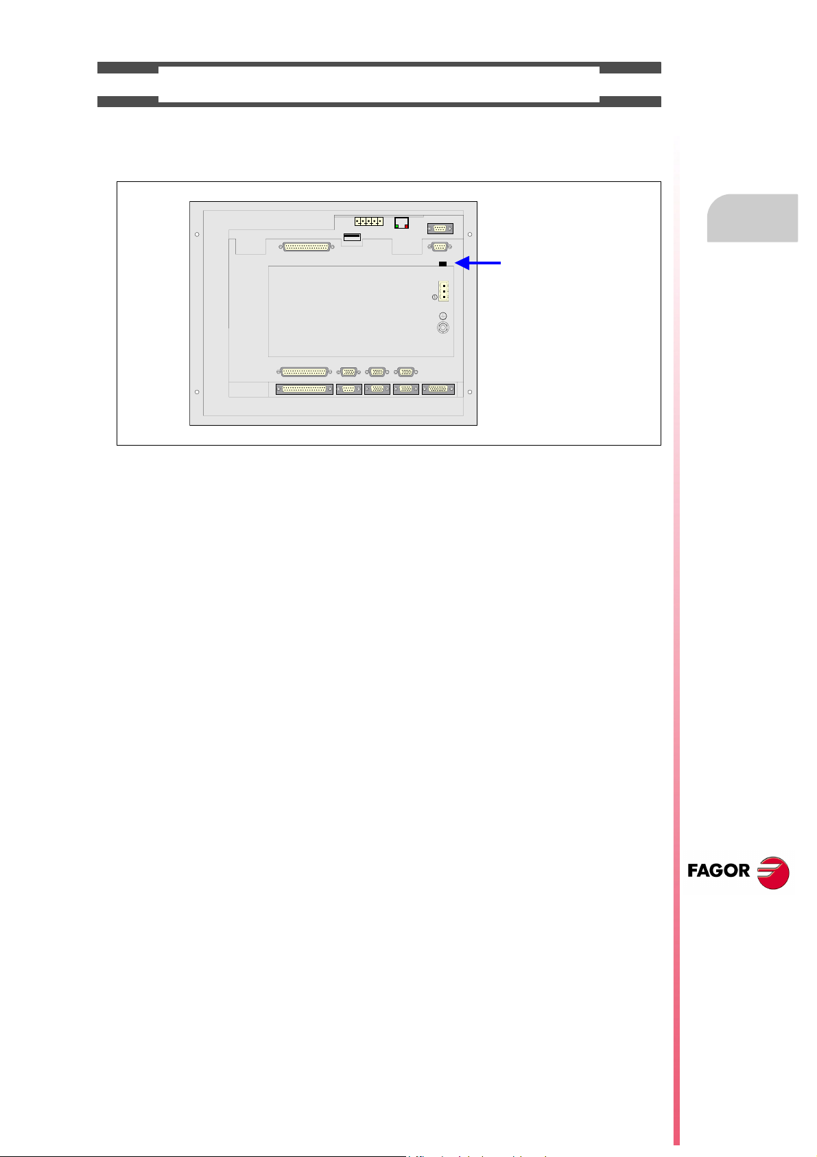
PROTECTIONS OF THE UNIT ITSELF (8037)
FUSE
X7
X1
X8
X9
X2
X10
X3
X11X4X12
X5
X6
+24V
0V
• Central Unit.
It has a 4 A 250V external fast fuse (F).
• Inputs-Outputs.
All the digital inputs and outputs have galvanic isolation via optocouplers between the CNC circuitry
and the outside.
Safety conditions
CNC 8037
·15·

PRECAUTIONS DURING REPAIR
i
Do not get into the inside of the unit. Only personnel authorized by Fagor Automation may manipulate
the inside of this unit.
Do not handle the connectors with the unit connected to main AC power. Before manipulating the
connectors (inputs/outputs, feedback, etc.) make sure that the unit is not connected to AC power.
SAFETY SYMBOLS
Safety conditions
• Symbols which may appear on the manual.
Symbol for danger or prohibition.
It indicates actions or operations that may cause damage to people or to units.
Warning symbol.
It indicates situations that may be caused by certain operations and the actions to be taken to prevent
them.
Obligation symbol.
It indicates actions and operations that must be carried out.
Information symbol.
It indicates notes, warnings and advises.
CNC 8037
·16·

WARRANTY TERMS
INITIAL WARRANTY
All products manufactured or marketed by FAGOR carry a 12-month warranty for the end user which could
be controlled by the our service network by means of the warranty control system established by FAGOR
for this purpose.
In order to prevent the possibility of having the time period from the time a product leaves our warehouse
until the end user actually receives it run against this 12-month warranty, FAGOR has set up a warranty
control system based on having the manufacturer or agent inform FAGOR of the destination, identification
and on-machine installation date, by filling out the document accompanying each FAGOR product in the
warranty envelope. This system, besides assuring a full year of warranty to the end user, enables our service
network to know about FAGOR equipment coming from other countries into their area of responsibility.
The warranty starting date will be the one appearing as the installation date on the above mentioned
document. FAGOR offers the manufacturer or agent 12 months to sell and install the product. This means
that the warranty starting date may be up to one year after the product has left our warehouse so long as
the warranty control sheet has been sent back to us. This translates into the extension of warranty period
to two years since the product left our warehouse. If this sheet has not been sent to us, the warranty period
ends 15 months from when the product left our warehouse.
This warranty covers all costs of material and labour involved in repairs at FAGOR carried out to correct
malfunctions in the equipment. FAGOR under takes to repair or replace their products within the period from
the moment manufacture begins until 8 years after the date on which it disappears from the catalog.
FAGOR has exclusive competence in deciding whether the repair enters within the term defined as the
warranty period.
EXCLUDING CLAUSES
Repairs will be carried out on our premises. Therefore, all expenses incurred as a result of trips made by
technical personnel to carry out equipment repairs, despite these being within the above-mentioned period
of warranty, are not covered by the warranty.
Said warranty will be applied whenever the equipment has been installed in accordance with instructions,
has not be mistreated, has not been damaged by accident or by negligence and has not been tampered
with by personnel not authorized by FAGOR. If, once servicing or repairs have been made, the cause of
the malfunction cannot be attributed to said elements, the customer is obliged to cover the expenses
incurred, in accordance with the tariffs in force.
Other warranties, implicit or explicit, are not covered and FAGOR AUTOMATION cannot be held responsible
for other damages which may occur.
CNC 8037
·17·

WARRANTY ON REPAIRS
In a similar way to the initial warranty, FAGOR offers a warranty on standard repairs according to the
following conditions:
PERIOD
CONCEPT
EXCLUDING CLAUSES
When the customer does not choose the standard repair and just the faulty material has been replaced,
Warranty terms
the warranty will cover just the replaced parts or components within 12 months.
For sold parts the warranty is 12 moths length.
The SERVICE CONTRACT is available for the distributor or manufacturer who buys and installs our CNC
systems.
12 months.
Covers parts and labor for repairs (or replacements) at the network's own
facilities.
The same as those applied regarding the chapter on initial warranty.
If the repair is carried out within the warranty period, the warranty extension
has no effect.
MAINTENANCE CONTRACTS
CNC 8037
·18·

MATERIAL RETURNING TERMS
When sending the central nit or the remote modules, pack them in its original package and packaging
material. If the original packaging material is not available, pack it as follows:
1. Get a cardboard box whose three inside dimensions are at least 15 cm (6 inches) larger than those
of the unit. The cardboard being used to make the box must have a resistance of 170 kg. (375 pounds).
2. Attach a label indicating the owner of the unit, person to contact, type of unit and serial number.
3. In case of failure, also indicate the symptom and a short description.
4. Wrap the unit in a polyethylene roll or similar material to protect it.
5. When sending the central unit, protect especially the screen.
6. Pad the unit inside the cardboard box with polyurethane foam on all sides.
7. Seal the cardboard box with packing tape or industrial staples.
CNC 8037
·19·

Material returning terms
CNC 8037
·20·

ADDITIONAL REMARKS
Mount the CNC away from coolants, chemical products, blows, etc. which could damage it. Before turning
the unit on, verify that the ground connections have been properly made.
In case of a malfunction or failure, disconnect it and call the technical service. Do not get into the inside
of the unit.
CNC 8037
·21·

Additional remarks
CNC 8037
·22·

FAGOR DOCUMENTATION
OEM manual
It is directed to the machine builder or person in charge of installing and starting-up the CNC.
USER-M manual
Directed to the end user.
It describes how to operate and program in M mode.
USER-T manual
Directed to the end user.
It describes how to operate and program in T mode.
TC Manual
Directed to the end user.
It describes how to operate and program in TC mode.
It contains a self-teaching manual.
CNC 8037
·23·

Fagor documentation
CNC 8037
·24·

GENERAL CONCEPTS
1
The CNC may be programmed at the machine (from the front panel) and from a peripheral
(computer). Memory available to the user for carrying out the part programs is 1 Mbyte.
The part programs and the values in the tables which the CNC has can be entered from the front
panel, from a pc (DNC) or from a peripheral.
Entering programs and tables from the front panel.
Once the editing mode or desired table has been selected, the CNC allows you to enter data from
the keyboard.
Entering programs and tables from a Computer (DNC) or peripheral device.
The CNC allows data to be exchanged with a computer or peripheral device, using the RS232C serial
line.
If this is controlled from the CNC, it is necessary to preset the corresponding table or part program
directory (utilities) you want to communicate with.
Depending on the type of communication required, the ser ial port machine parameter "PROTOCOL"
should be set.
"PROTOCOL" = 0 If the communication is with a peripheral device.
"PROTOCOL" = 1 If the communication is via DNC.
CNC 8037
·T· MODEL
SOFT: V01.4X
·25·

1.
1.1 Part programs
Part programs
Programming manual
The operating manual describes the different operating modes. Refer to that manual for further
information.
Editing a part-program
To create a part-program, access the –Edit– mode.
The new part-program edited is stored in the CNC's RAM memory. A copy of the part-programs may
be stored in the hard disk (KeyCF) at a PC connected through the serial line or in the USB disk.
To transmit a program to a PC through the serial, proceed as follows:
1. Execute the "WinDNC.exe" application program at the PC.
2. Activate DNC communications at the CNC.
3. Select the work directory at the CNC. It is selected from the –Utilities– mode, option Directory
\Serial L \Change directory
GENERAL CONCEPTS
In –Edit– mode, it is possible to modify part-programs residing in the CNC's RAM memory. To modify
a program stored in the hard disk (KeyCF), in a PC or in the USB disk, it must be previously copied
into RAM memory.
Executing and editing a part-program
Part-programs stored anywhere may be executed or simulated. Simulation is carried out in the
–Simulation– mode, whereas the execution is done in the –Automatic– mode
When executing or simulating a part-program, bear in mind the following points:
• Only subroutines stored in the CNC's RAM memory can be executed. Therefore, to execute a
subroutine stored in the hard disk (KeyCF), in a PC or in the USB disk, it must be first copied
into the CNC's RAM memory.
• The GOTO and RPT instructions cannot be used in programs that are executed from a PC
connected through the serial line.
• From a program in execution, it is possible to execute another program located in RAM memory,
in the hard disk (KeyCF) or in a PC using the EXEC instruction.
The user customizing programs must be in RAM memory so the CNC can execute them.
–Utilities– operating mode.
CNC 8037
·T· MODEL
SOFT: V01.4X
·26·
The –Utilities– mode, lets display the part-program directory of all the devices, make copies, delete,
rename and even set the protections for any of them.

Programming manual
Operations that may be carried out with part-programs.
See the program directory of ...
See the subroutine directory of ...
Create the work directory from ...
Change the work directory from ...
Edit a program from ...
Modify a program from ...
Delete a program from ...
Copy from/to RAM memory to/from ...
Copy from/to HD to/from ...
Copy from/to DNC to/from ...
Rename a program from ...
Change the comment of a program from ...
Change the protections of a program from ...
Execute a part-program from ...
Execute a user program from ...
Execute a PLC program from ...
Execute programs with GOTO or RPT instructions from ...
Execute subroutines residing in ...
Execute programs with the EXEC instruction, in RAM from ...
Execute programs with the EXEC instruction, in HD from ...
Execute programs with the EXEC instruction, in DNC from ...
RAM
memory
Ye s
Ye s
No
No
Ye s
Ye s
Ye s
Ye s
Ye s
Ye s
Ye s
Ye s
Ye s
Ye s
Ye s
Ye s
Ye s
Ye s
Ye s
Ye s
Ye s
Hard
disk
Ye s
No
No
No
Ye s
Ye s
Ye s
Ye s
Ye s
Ye s
Ye s
Ye s
Ye s
Ye s
Ye s
No
Ye s
No
Ye s
Ye s
Ye s
DNC
Ye s
No
No
Ye s
No
No
Ye s
Ye s
Ye s
Ye s
No
No
No
Ye s
No
No
No
No
Ye s
Ye s
No
1.
Part programs
GENERAL CONCEPTS
Open programs with the OPEN instruction, in RAM from ...
Open programs with the OPEN instruction, in HD from ...
Open programs with the OPEN instruction, in DNC from ...
Via Ethernet:
See from a PC the program directory of ...
See from a PC the subroutine directory of ...
See from a PC, a directory in ...
Ye s
Ye s
Ye s
No
No
No
Ye s
Ye s
Ye s
Ye s
No
No
(*) If it is not in RAM memory, it generates the executable code in RAM and it executes it.
Ethernet
When having the Ethernet option and if the CNC is configured as another node within the computer
network, the following operations are possible from any PC of the network:
• Access the part-program directory of the hard disk (KeyCF).
• Edit, modify, delete, rename, etc. the programs stored on the hard disk.
• Copy programs from the hard disk to the PC and vice versa.
To configure the CNC as another node within the computer network, see the installation manual.
Ye s
Ye s
No
No
No
No
CNC 8037
·T· MODEL
SOFT: V01.4X
·27·

1.
Part programs
GENERAL CONCEPTS
Programming manual
1.1.1 Considerations regarding the Ethernet connection
When configuring the CNC as another node in the computer network, the programs stored in the
hard disk (KeyCF) may be edited and modified from any PC.
Instructions for setting up a PC to access CNC directories
To set up the PC to access the CNC directories, we recommend to proceed as follows.
1. Open the "Windows Explorer"
2. On the "Tools" menu, select the "Connect to Network Drives" option.
3. Select the drive, for example "D".
4. Indicate the path. The path will be the CNC name followed by the name of the shared directory.
For example: \\FAGORCNC\CNCHD
5. When selecting the option: "Connect again when initiating the session", the selected CNC will
appear on each power-up as another path of the "Windows Explorer" without having to define
it again.
Data format
This connection is established through Ethernet and, therefore, the CNC does not control the syntax
of the programs while they are received or modified. However, whenever accessing the program
directory of the Hard Disk (HD), the following verification takes place:
File name.
The file number must always have 6 digits and the extension PIM (for milling) or PIT (for lathe).
Examples: 001204.PIM 000100.PIM 123456.PIT 020150.PIT
If the file has been given the wrong name, for example: 1204.PIM or 100.PIT, the CNC will not change
it, but it will display it with the comment "****************". The file name cannot be modified
at the CNC; it must be edited from the PC to correct the error.
File size.
If the file is empty (size = 0) the CNC will display it with the comment "********************".
The file can be edited or deleted either from the CNC or from the PC.
First line of the program.
The first line of the program must have the % character, the comment associated with the file (up
to 20 characters) and between the two commas (,) the program attributes O (OEM), H (hidden), M
(modifiable), X (executable).
Examples: %Comment ,MX,
% ,OMX,
CNC 8037
·T· MODEL
SOFT: V01.4X
·28·
If the first line does not exist, the CNC will display the program with an empty comment and with
the modifiable (M) and executable (X) attributes.
When the format of the first line is wrong, the CNC does not modify it, but it displays it with the
comment "****************". The file can be edited or deleted either from the CNC or from the
PC.
The format is incorrect when the comment has more than 20 characters, a comma (,) is missing
to group the attributes or there is a strange character in the attributes.

Programming manual
1.2 DNC connection
The CNC offers as optional feature the possibility of working in DNC (Distributed Numerical Control),
enabling communication between the CNC and a computer to carry out the following functions:
• Directory and delete commands.
• Transfer of programs and tables between the CNC and a computer.
• Remote control of the machine.
• The ability to supervise the status of advanced DNC systems.
1.
DNC connection
GENERAL CONCEPTS
CNC 8037
·T· MODEL
SOFT: V01.4X
·29·

1.
GENERAL CONCEPTS
Communication protocol via DNC or peripheral device
Programming manual
1.3 Communication protocol via DNC or peripheral device
This type of communication enables program-and-table transfer commands, plus the organization
of CNC directories such as the computer directory, for copying/deleting programs, etc. to be done
either from the CNC or the computer.
When you want to transfer files, it is necessary to follow this protocol:
• The "%" symbol will be used to start the file, followed by the program comment (optional), of up
to 20 characters.
Then, and separated by a comma ",", comes the protection of each file, read, write, etc. These
protections are optional and need not be programmed.
To end the file header, RT (RETURN ) or LF (LINE FEED) characters should be sent separated
by a comma (",").
Example: %Fagor Automation, MX, RT
• Following the header, the file blocks should be programmed. These will all be programmed
according to the programming rules indicated in this manual. After each block, to separate it from
the others, the RT (RETURN ) or LF (LINE FEED) characters should be used.
Example: N20 G90 G01 X100 Y200 F2000 LF
(RPT N10, N20) N3 LF
If communication is made with a peripheral device, you will need to send the ‘end of file’ command.
This command is selected via the machine parameter for the serial port: "EOFCHR", and can be
one of the following characters :
ESC ESCAPE
EOT END OF TRANSMISSION
SUB SUBSTITUTE
EXT END OF TRANSMISSION
CNC 8037
·T· MODEL
SOFT: V01.4X
·30·
 Loading...