


CNC
8037
Installation manual
Ref. 1310
Soft: V01.4x

It is possible that CNC can execute more functions than those described in its
associated documentation; however, Fagor Automation does not guarantee the
validity of those applications. Therefore, except under the express permission
from Fagor Automation, any CNC application that is not described in the
documentation must be considered as "impossible". In any case, Fagor
Automation shall not be held responsible for any personal injuries or physical
All rights reserved. No part of this documentation may be transmitted,
transcribed, stored in a backup device or translated into another language
without Fagor Automation’s consent. Unauthorized copying or distributing of this
software is prohibited.
The information described in this manual may be subject to changes due to
technical modifications. Fagor Automation reserves the right to change the
contents of this manual without prior notice.
All the trade marks appearing in the manual belong to the corresponding owners.
The use of these marks by third parties for their own purpose could violate the
rights of the owners.
This product uses the following source code, subject to the terms of the GPL license. The applications busybox V0.60.2;
dosfstools V2.9; linux-ftpd V0.17; ppp V2.4.0; utelnet V0.1.1. The librarygrx V2.4.4. The linux kernel V2.4.4. The linux boot
ppcboot V1.1.3. If you would like to have a CD copy of this source code sent to you, send 10 Euros to Fagor Automation
for shipping and handling.
damage caused or suffered by the CNC if it is used in any way other than as
explained in the related documentation.
The content of this manual and its validity for the product described here has been
verified. Even so, involuntary errors are possible, hence no absolute match is
guaranteed. However, the contents of this document are regularly checked and
updated implementing the necessary corrections in a later edition. We appreciate
your suggestions for improvement.
The examples described in this manual are for learning purposes. Before using
them in industrial applications, they must be properly adapted making sure that
the safety regulations are fully met.

Installation manual
About the product ......................................................................................................................... 7
Declaration of conformity .............................................................................................................. 9
Version history ............................................................................................................................ 11
Safety conditions ........................................................................................................................ 13
Warranty terms ........................................................................................................................... 17
Material returning terms.............................................................................................................. 19
Additional remarks ...................................................................................................................... 21
Fagor documentation.................................................................................................................. 23
CHAPTER 1 CNC CONFIGURATION
1.1 CNC structure ................................................................................................................26
1.1.1 Connectors.................................................................................................................28
CHAPTER 2 HEAT DISSIPATION
2.1 Heat dissipation by natural convection .......................................................................... 52
2.2 Heat dissipation by forced convection with inside fan.................................................... 53
2.3 Heat dissipation by air flow to the outside using a fan ................................................... 54
INDEX
CHAPTER 3 REMOTE MODULES (BUS CAN WITH CANOPEN PROTOCOL)
3.1 Installation of the modules ............................................................................................. 57
3.2 Power supply .................................................................................................................58
3.3 Digital inputs and digital outputs (single module)........................................................... 64
3.4 Digital inputs and digital outputs (double module) ......................................................... 66
3.5 Electrical characteristics of the inputs and outputs ........................................................ 68
3.6 Numbering of the digital inputs and outputs................................................................... 70
CHAPTER 4 MACHINE AND POWER CONNECTION
4.1 Digital inputs and outputs............................................................................................... 74
4.2 Analog inputs and outputs ............................................................................................. 75
4.3 Setup.............................................................................................................................. 76
4.4 Connection of the emergency input and output ............................................................. 80
CHAPTER 5 MACHINE PARAMETERS
5.1 Parameters that may be modified from the oscilloscope, OEM program or OEM
5.2 General machine parameters ........................................................................................ 91
5.3 Axis parameters .......................................................................................................... 131
5.4 Spindle parameters...................................................................................................... 159
5.5 Drive parameters ......................................................................................................... 176
5.6 Serial line parameters .................................................................................................. 178
5.7 Ethernet parameters .................................................................................................... 181
5.8 PLC Parameters ......................................................................................................... 185
5.9 Tables ......................................................................................................................... 192
5.9.1 Miscellaneous (M) function table.............................................................................. 192
5.9.2 Leadscrew error compensation table ....................................................................... 194
5.9.3 Cross compensation parameter table ...................................................................... 196
subroutine................................................................................................................ 89
CHAPTER 6 CONCEPTS
6.1 Axes and coordinate systems ...................................................................................... 197
6.1.1 Rotary axes .............................................................................................................. 200
6.1.2 Gantry axes.............................................................................................................. 202
6.1.3 Incline axis ............................................................................................................... 203
6.2 Jog ............................................................................................................................... 205
6.2.1 Relationship between the axes and the JOG keys .................................................. 205
6.2.2 Path-jog mode.......................................................................................................... 206
CNC 8037
SOFT: V01.4X
·3·

Installation manual
6.3 Movement with an electronic handwheel .................................................................... 208
6.3.1 Standard handwheel ................................................................................................ 209
6.3.2 Path handwheel ....................................................................................................... 210
6.3.3 Feed handwheel mode ............................................................................................ 211
6.3.4 "Additive handwheel" mode ..................................................................................... 212
6.4 feedback system.......................................................................................................... 214
6.4.1 Counting speed limitation......................................................................................... 215
6.4.2 Resolution ................................................................................................................ 216
6.5 Axis adjustment ........................................................................................................... 220
6.5.1 Drive setting ............................................................................................................. 221
6.5.2 Gain setting.............................................................................................................. 222
6.5.3 Proportional gain setting .......................................................................................... 223
6.5.4 Feed-forward gain setting ........................................................................................ 224
6.5.5 Derivative (AC-forward) gain setting ........................................................................ 225
6.5.6 Leadscrew backlash compensation. ........................................................................ 226
6.5.7 Leadscrew error compensation................................................................................ 227
6.5.8 Circle geometry test ................................................................................................. 229
6.6 Reference systems ...................................................................................................... 231
6.6.1 Home search............................................................................................................ 232
6.6.2 Setting on systems without distance-coded feedback ............................................. 235
6.6.3 Setting on systems with distance-coded feedback .................................................. 237
6.6.4 Axis travel limits (software limits) ............................................................................. 238
6.7 Unidirectional approach ............................................................................................... 239
6.8 Auxiliary M, S, T function transfer................................................................................ 240
6.8.1 Transferring M, S, T using the AUXEND signal ....................................................... 242
6.8.2 Transferring the auxiliary (miscellaneous) M functions without the AUXEND signal 243
6.9 Spindle......................................................................................................................... 244
6.9.1 Spindle types ........................................................................................................... 244
6.9.2 Spindle speed (S) control......................................................................................... 245
6.9.3 Spindle gear change ................................................................................................ 247
6.9.4 Spindle in closed loop .............................................................................................. 249
6.10 Treatment of emergency signals ................................................................................. 255
6.11 Digital CAN servo ........................................................................................................ 258
6.11.1 Communications channel......................................................................................... 258
6.11.2 Drive’s absolute feedback........................................................................................ 261
6.12 Fagor handwheels: HBA, HBE and LGB .................................................................... 262
6.13 Machine safety related functions ................................................................................. 266
6.13.1 Maximum machining spindle speed......................................................................... 266
6.13.2 Cycle start disabled when hardware errors occur.................................................... 267
6.14 Tool magazine ............................................................................................................. 268
6.14.1 Tool change via PLC................................................................................................ 268
6.14.2 Tool magazine management ................................................................................... 269
6.15 Gear ratio management on axes and spindle.............................................................. 270
6.15.1 Axis example: Encoder at the motor ........................................................................ 271
6.15.2 Axis example: external feedback device without a gear box ................................... 272
6.15.3 Axis example: external feedback device with gear box ........................................... 275
6.15.4 Spindle example: Encoder at the motor................................................................... 277
6.15.5 Spindle example: external encoder without gear box .............................................. 279
6.15.6 Spindle example: external encoder with gear box ................................................... 281
CNC 8037
SOFT: V01.4X
·4·
CHAPTER 7 PLC RESOURCES
7.1 Inputs ........................................................................................................................... 283
7.2 Outputs ........................................................................................................................ 284
7.3 Marks ........................................................................................................................... 285
7.4 Registers...................................................................................................................... 287
7.5 Timers.......................................................................................................................... 288
7.5.1 Monostable mode. TG1 input................................................................................... 291
7.5.2 Delayed activation mode. TG2 input........................................................................ 293
7.5.3 Delayed deactivation mode. TG3 input.................................................................... 295
7.5.4 Signal limiting mode. TG4 Input............................................................................... 297
7.6 Counters ...................................................................................................................... 299
7.6.1 Operating mode of a counter ................................................................................... 302
CHAPTER 8 INTRODUCTION TO THE PLC
8.1 PLC resources ............................................................................................................. 304
8.2 PLC program execution ............................................................................................... 305
8.3 Loop time ..................................................................................................................... 308
8.4 Modular structure of the program ................................................................................ 309
8.4.1 First cycle module (CY1).......................................................................................... 310
8.4.2 Main module (PRG) ................................................................................................. 311
8.4.3 Periodic execution module (PE t)............................................................................. 312
8.4.4 Priority of execution of the PLC modules................................................................. 313

Installation manual
CHAPTER 9 PLC PROGRAMMING
9.1 Module structure .......................................................................................................... 316
9.2 Directing instructions.................................................................................................... 317
9.3 Consulting instructions................................................................................................. 320
9.4 Operators and symbols................................................................................................ 322
9.5 Action instruction.......................................................................................................... 323
9.5.1 Binary assignment instructions ................................................................................ 324
9.5.2 Conditional binary action instructions....................................................................... 325
9.5.3 Sequence breaking action instructions .................................................................... 326
9.5.4 Arithmetic action instructions ................................................................................... 327
9.5.5 Logic action instructions........................................................................................... 329
9.5.6 Specific action instructions....................................................................................... 331
CHAPTER 10 CNC-PLC COMMUNICATION
10.1 Auxiliary M, S, T functions ........................................................................................... 334
10.2 Auxiliary M, S, T function transfer ................................................................................ 337
10.2.1 Transferring M, S, T using the AUXEND signal ....................................................... 338
10.2.2 Transferring the auxiliary (miscellaneous) M functions without the AUXEND signal 339
10.3 Displaying messages, errors and screens ................................................................... 340
10.4 Access to the PLC from the CNC ................................................................................ 342
10.5 Access to the PLC from a PC, via DNC....................................................................... 343
CHAPTER 11 LOGIC CNC INPUTS AND OUTPUTS
11.1 General logic inputs ..................................................................................................... 346
11.2 Axis logic inputs. .......................................................................................................... 355
11.3 Spindle logic inputs. ..................................................................................................... 360
11.4 Key inhibiting logic inputs............................................................................................. 365
11.5 Logic inputs of the PLC channel .................................................................................. 366
11.6 General logic outputs ................................................................................................... 368
11.7 Logic outputs of the axes ............................................................................................. 375
11.8 Spindle logic outputs.................................................................................................... 377
11.9 Logic outputs of key status .......................................................................................... 378
CHAPTER 12 ACCESS TO INTERNAL CNC VARIABLES
12.1 Variables associated with tools.................................................................................... 381
12.2 Variables associated with zero offsets......................................................................... 385
12.3 Variables associated with machine parameters........................................................... 386
12.4 Variables associated with work zones ......................................................................... 387
12.5 Variables associated with feedrates ............................................................................ 389
12.6 Variables associated with coordinates......................................................................... 392
12.7 Variables associated with electronic handwheels........................................................ 394
12.8 Variables associated with feedback............................................................................. 396
12.9 Variables associated with the main spindle ................................................................. 397
12.10 Variables associated with local and global parameters ............................................... 400
12.11 Operating-mode related variables................................................................................ 401
12.12 Other variables............................................................................................................. 404
CHAPTER 13 AXES CONTROLLED FROM THE PLC
13.1 PLC execution channel ................................................................................................ 414
13.1.1 Considerations ......................................................................................................... 415
13.1.2 Blocks which can be executed from the PLC........................................................... 417
13.1.3 Control of the PLC program from the CNC .............................................................. 421
13.2 Action CNCEX1 ........................................................................................................... 423
CHAPTER 14 PLC PROGRAMMING EXAMPLE
14.1 Definition of symbols (mnemonics) .............................................................................. 426
14.2 First cycle module. ....................................................................................................... 428
14.3 Main module. ............................................................................................................... 429
CNC 8037
SOFT: V01.4X
·5·

APPENDIX
Installation manual
A CNC technical characteristics...................................................................................... 439
B Probe connection......................................................................................................... 443
C Summary of internal CNC variables. ........................................................................... 445
D Summary of PLC commands....................................................................................... 451
E Summary of PLC inputs and outputs ........................................................................... 455
F 2-digit BCD code output conversion table ................................................................... 461
G Key code...................................................................................................................... 463
H Logic outputs of key status .......................................................................................... 465
I Key inhibiting codes..................................................................................................... 467
J Machine parameter setting chart ................................................................................. 469
K M functions setting chart.............................................................................................. 475
L Leadscrew error compensation table........................................................................... 477
M Cross compensation table ........................................................................................... 479
N Maintenance ................................................................................................................ 481
CNC 8037
SOFT: V01.4X
·6·

ABOUT THE PRODUCT
BASIC CHARACTERISTICS
Monitor 7.5" Color LCD
Block processing time 7 ms
Look-ahead 75 blocks
RAM memory 1 Mb
Flash memory 128 MB
PLC cycle time 3 ms / 1000 instructions
Minimum position loop 4 ms
USB Standard
RS-232 serial line Standard
DNC ( via RS232 ) Standard
Ethernet Option
5 V or 24 V probe inputs 2
Local digital inputs and outputs. 16 I / 8 O
40 I / 24 O
56 I / 32 O
Feedback inputs for the axes and spindle 4 TTL / 1Vpp inputs
Feedback inputs for handwheels 2 TTL inputs
Analog outputs 4 for axes and spindle
CAN servo drive system for Fagor servo drive connection. Option
Remote CAN modules, for digital I/O expansion (RIO). Option
Before start-up, verify that the machine that integrates this CNC meets the 89/392/CEE Directive.
CNC 8037
·7·

About the product
SOFTWARE OPTIONS
Model
M T TC
Number of axes 3 2 2
Number of spindles 1 1 1
Electronic threading Standard Standard Standard
Tool magazine management: Standard Standard Standard
Machining canned cycles Standard Standard Standard
Multiple machining Standard ----- -----
Rigid tapping Standard Standard Standard
DNC Standard Standard Standard
Tool radius compensation Standard Standard Standard
Retracing Standard ----- -----
Jerk control Standard Standard Standard
Feed forward Standard Standard Standard
Oscilloscope function (Setup assistance) Standard Standard Standard
Roundness test (Setup assistance) Standard Standard Standard
CNC 8037
·8·
DECLARATION OF CONFORMITY
The manufacturer:
Fagor Automation S. Coop.
Barrio de San Andrés Nº 19, C.P. 20500, Mondragón -Guipúzcoa- (SPAIN).
Declares:
Under their responsibility that the product:
8037 CNC
Consisting of the following modules and accessories:
8037-M, 8037-T, 8037-TC
Remote modules RIO
ETHERNET, ETHERNET-CAN-CAN AXES, ETHERNET-CAN AXES
Note.
Some additional characters may follow the references mentioned above. They all comply with the directives
listed. However, check that that's the case by checking the label of the unit itself.
Referred to by this declaration with following directives:
Low voltage regulations.
EN 60204-1: 2006 Electrical equipment on machines — Part 1. General requirements.
Regulation on electromagnetic compatibility.
EN 61131-2: 2007 PLC — Part 2. Requirements and equipment tests.
As instructed by the European Community Directives 2006/95/EEC on Low Voltage and
2004/108/EC on Electromagnetic Compatibility and its updates.
In Mondragón, March 14th, 2012
CNC 8037
·9·


VERSION HISTORY
Here is a list of the features added in each software version and the manuals that describe them.
The version history uses the following abbreviations:
INST Installation manual
PRG Programming manual
OPT Operating manual
OPT-TC Operating manual for the TC option.
Software V01.42 March 2012
First version.
CNC 8037
·11·

Version history
CNC 8037
·12·

SAFETY CONDITIONS
Read the following safety measures in order to prevent harming people or damage to this product and those
products connected to it.
This unit may only be repaired by authorized personnel at Fagor Automation.
Fagor Automation shall not be held responsible of any physical damage or defective unit resulting from not
complying with these basic safety regulations.
PRECAUTIONS AGAINST PERSONAL DAMAGE
• Interconnection of modules.
Use the connection cables provided with the unit.
• Use proper Mains AC power cables
To avoid risks, use only the Mains AC cables recommended for this unit.
• Avoid electrical overloads.
In order to avoid electrical discharges and fire hazards, do not apply electrical voltage outside the range
selected on the rear panel of the central unit.
• Ground connection.
In order to avoid electrical discharges, connect the ground terminals of all the modules to the main
ground terminal. Before connecting the inputs and outputs of this unit, make sure that all the grounding
connections are properly made.
• Before powering the unit up, make sure that it is connected to ground.
In order to avoid electrical discharges, make sure that all the grounding connections are properly made.
• Do not work in humid environments.
In order to avoid electrical discharges, always work under 90% of relative humidity (non-condensing)
and 45 ºC (113º F).
• Do not work in explosive environments.
In order to avoid risks or damages, do no work in explosive environments.
CNC 8037
·13·

CNC 8037
• Working environment.
This unit is ready to be used in industrial environments complying with the directives and regulations
effective in the European Community.
Fagor Automation shall not be held responsible for any damage suffered or caused when installed in
other environments (residential or homes).
• Install this unit in the proper place.
It is recommended, whenever possible, to install the CNC away from coolants, chemical product, blows,
etc. that could damage it.
This unit complies with the European directives on electromagnetic compatibility. Nevertheless, it is
recommended to keep it away from sources of electromagnetic disturbance such as:
Powerful loads connected to the same AC power line as this equipment.
Safety conditions
Nearby portable transmitters (Radio-telephones, Ham radio transmitters).
Nearby radio/TV transmitters.
Nearby arc welding machines.
Nearby High Voltage power lines.
Etc.
•Enclosures.
The manufacturer is responsible of assuring that the enclosure involving the equipment meets all the
currently effective directives of the European Community.
• Avoid disturbances coming from the machine tool.
The machine-tool must have all the interference generating elements (relay coils, contactors, motors,
etc.) uncoupled.
DC relay coils. Diode type 1N4000.
AC relay coils. RC connected as close to the coils as possible with approximate values of R=220
AC motors. RC connected between phases, with values of R=300 / 6 W y C=0,47 µF / 600 V.
• Use the proper power supply.
Use an external regulated 24 Vdc power supply for the inputs and outputs.
• Grounding of the power supply.
The zero volt point of the external power supply must be connected to the main ground point of the
machine.
• Analog inputs and outputs connection.
It is recommended to connect them using shielded cables and connecting their shields (mesh) to the
corresponding pin.
• Ambient conditions.
The working temperature must be between +5 ºC and +40 ºC (41ºF and 104º F)
The storage temperature must be between -25 ºC and +70 ºC. (-13 ºF and 158 ºF)
• Central unit enclosure (8037 CNC).
Make sure that the needed gap is kept between the central unit and each wall of the enclosure. Use
a DC fan to improve enclosure ventilation.
• Power switch.
This power switch must be mounted in such a way that it is easily accessed and at a distance between
0.7 meters (27.5 inches) and 1.7 meters (5.5ft) off the floor.
PRECAUTIONS AGAINST PRODUCT DAMAGE
1 W y C=0,2 µF / 600 V.
·14·

PROTECTIONS OF THE UNIT ITSELF (8037)
FUSE
X7
X1
X8
X9
X2
X10
X3
X11X4X12
X5
X6
+24V
0V
• Central Unit.
It has a 4 A 250V external fast fuse (F).
• Inputs-Outputs.
All the digital inputs and outputs have galvanic isolation via optocouplers between the CNC circuitry
and the outside.
Safety conditions
CNC 8037
·15·
PRECAUTIONS DURING REPAIR
i
Do not get into the inside of the unit. Only personnel authorized by Fagor Automation may manipulate
the inside of this unit.
Do not handle the connectors with the unit connected to main AC power. Before manipulating the
connectors (inputs/outputs, feedback, etc.) make sure that the unit is not connected to AC power.
SAFETY SYMBOLS
Safety conditions
• Symbols which may appear on the manual.
Symbol for danger or prohibition.
It indicates actions or operations that may cause damage to people or to units.
Warning symbol.
It indicates situations that may be caused by certain operations and the actions to be taken to prevent
them.
Obligation symbol.
It indicates actions and operations that must be carried out.
Information symbol.
It indicates notes, warnings and advises.
CNC 8037
·16·

WARRANTY TERMS
INITIAL WARRANTY
All products manufactured or marketed by FAGOR carry a 12-month warranty for the end user which could
be controlled by the our service network by means of the warranty control system established by FAGOR
for this purpose.
In order to prevent the possibility of having the time period from the time a product leaves our warehouse
until the end user actually receives it run against this 12-month warranty, FAGOR has set up a warranty
control system based on having the manufacturer or agent inform FAGOR of the destination, identification
and on-machine installation date, by filling out the document accompanying each FAGOR product in the
warranty envelope. This system, besides assuring a full year of warranty to the end user, enables our service
network to know about FAGOR equipment coming from other countries into their area of responsibility.
The warranty starting date will be the one appearing as the installation date on the above mentioned
document. FAGOR offers the manufacturer or agent 12 months to sell and install the product. This means
that the warranty starting date may be up to one year after the product has left our warehouse so long as
the warranty control sheet has been sent back to us. This translates into the extension of warranty period
to two years since the product left our warehouse. If this sheet has not been sent to us, the warranty period
ends 15 months from when the product left our warehouse.
This warranty covers all costs of material and labour involved in repairs at FAGOR carried out to correct
malfunctions in the equipment. FAGOR undertakes to repair or replace their products within the period from
the moment manufacture begins until 8 years after the date on which it disappears from the catalog.
FAGOR has exclusive competence in deciding whether the repair enters within the term defined as the
warranty period.
EXCLUDING CLAUSES
Repairs will be carried out on our premises. Therefore, all expenses incurred as a result of trips made by
technical personnel to carry out equipment repairs, despite these being within the above-mentioned period
of warranty, are not covered by the warranty.
Said warranty will be applied whenever the equipment has been installed in accordance with instructions,
has not be mistreated, has not been damaged by accident or by negligence and has not been tampered
with by personnel not authorized by FAGOR. If, once servicing or repairs have been made, the cause of
the malfunction cannot be attributed to said elements, the customer is obliged to cover the expenses
incurred, in accordance with the tariffs in force.
Other warranties, implicit or explicit, are not covered and FAGOR AUTOMATION cannot be held responsible
for other damages which may occur.
CNC 8037
·17·

WARRANTY ON REPAIRS
In a similar way to the initial warranty, FAGOR offers a warranty on standard repairs according to the
following conditions:
PERIOD
CONCEPT
EXCLUDING CLAUSES
When the customer does not choose the standard repair and just the faulty material has been replaced,
Warranty terms
the warranty will cover just the replaced parts or components within 12 months.
For sold parts the warranty is 12 moths length.
The SERVICE CONTRACT is available for the distributor or manufacturer who buys and installs our CNC
systems.
12 months.
Covers parts and labor for repairs (or replacements) at the network's own
facilities.
The same as those applied regarding the chapter on initial warranty.
If the repair is carried out within the warranty period, the warranty extension
has no effect.
MAINTENANCE CONTRACTS
CNC 8037
·18·

MATERIAL RETURNING TERMS
When sending the central nit or the remote modules, pack them in its original package and packaging
material. If the original packaging material is not available, pack it as follows:
1. Get a cardboard box whose three inside dimensions are at least 15 cm (6 inches) larger than those
of the unit. The cardboard being used to make the box must have a resistance of 170 kg. (375 pounds).
2. Attach a label indicating the owner of the unit, person to contact, type of unit and serial number.
3. In case of failure, also indicate the symptom and a short description.
4. Wrap the unit in a polyethylene roll or similar material to protect it.
5. When sending the central unit, protect especially the screen.
6. Pad the unit inside the cardboard box with polyurethane foam on all sides.
7. Seal the cardboard box with packing tape or industrial staples.
CNC 8037
·19·

Material returning terms
CNC 8037
·20·

ADDITIONAL REMARKS
Mount the CNC away from coolants, chemical products, blows, etc. which could damage it. Before turning
the unit on, verify that the ground connections have been properly made.
In case of a malfunction or failure, disconnect it and call the technical service. Do not get into the inside
of the unit.
CNC 8037
·21·

Additional remarks
CNC 8037
·22·

FAGOR DOCUMENTATION
OEM manual
It is directed to the machine builder or person in charge of installing and starting-up the CNC.
USER-M manual
Directed to the end user.
It describes how to operate and program in M mode.
USER-T manual
Directed to the end user.
It describes how to operate and program in T mode.
TC Manual
Directed to the end user.
It describes how to operate and program in TC mode.
It contains a self-teaching manual.
CNC 8037
·23·

Fagor documentation
CNC 8037
·24·

CNC CONFIGURATION
1
The CNC is prepared to be used in industrial environments, especially on milling machines, lathes,
etc.
The CNC can control machine movements and devices.
CNC 8037
SOFT: V01.4X
·25·
1.
115.5 [4.54]
222.35 [8.8]
318 [12.51]
287.8 [11.3]
8.5 [0.3]
352 [13.9]
335 [13.2]
40 [1.6] 193 [7.6]
273 [10.7]
56.3 [2.21]
125 [4.92]
Installation manual
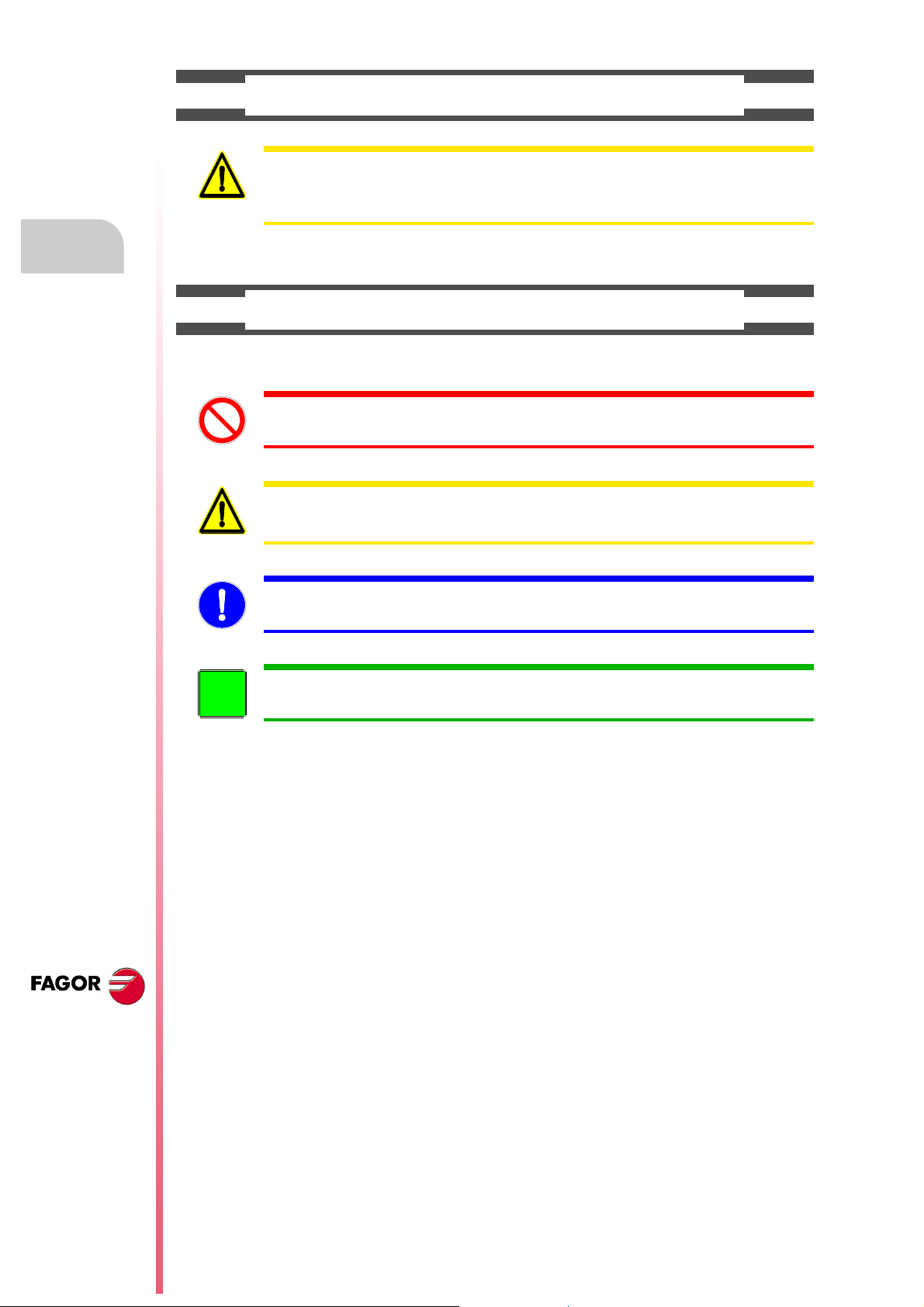
1.1 CNC structure
The central unit is located on the rear of the monitor.
CNC structure
CNC CONFIGURATION
Keyboard auto-identification
The keyboard has an auto-identification system. With this system, parameter CUSTOMTY is
updated (refreshed) automatically.
Dimensions
CNC 8037
SOFT: V01.4X
·26·
Installation manual
32 [1.26]
335 [13.2]
M5x0.7
6 [ 0.236]
323 [12.72]
193 [7.6]
257 [10.12]
50 [1.968]
50 [1.9 68]
50 [1.968]
50 [1.968]
180 [7.087]
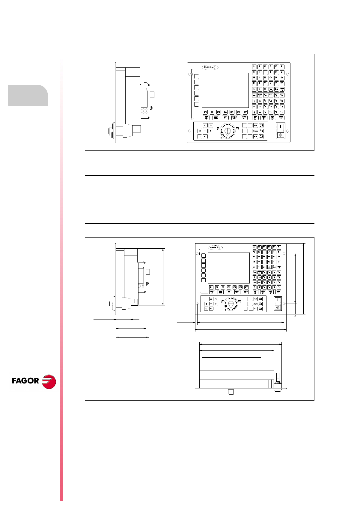
Enclosure
The minimum distance from each side of the monitor to its enclosure in order to guarantee the
required ambient conditions is shown below:
1.
CNC structure
CNC CONFIGURATION
It is up to the installer to make sure that the enclosure has forced ventilation or ventilation grooves
in order to prevent the inside temperature to exceed the specified ambient temperature.
Between 5º C and +50º C (41º F and 122º F)
Relative humidity between 5% and 95% non condensing
When using a fan to better ventilate the enclosure, a DC fan must be used since an AC fan may
generate electromagnetic interference resulting in distorted images being displayed by the CRT.
CNC 8037
SOFT: V01.4X
·27·

1.
+24V
0V
X9 X11X10 X12
X2 X3 X4 X5 X6
X8
X7
X1
B
A
C
D
E
F
Installation manual
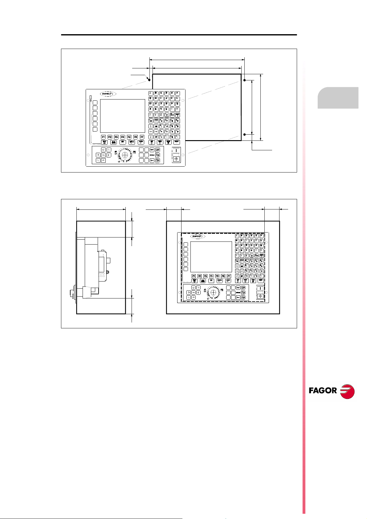
1.1.1 Connectors
The connectors are located in the rear of the CNC.
CNC structure
CNC CONFIGURATION
(A) Power supply.
(B) Ground connection.
(C) To connect the USB hard disk (Pen Drive) or USB extension cable.
(D) To connect the keyboard signal.
(E) Communications board
(F) Compact flash memory with the CNC configuration (KeyCF).
X1 For RS232 serial line connection.
X2 For digital I/O connection (I1 through I16 and O1 through O8).
X3 For probe connection.
X4 For analog spindle connection.
X5 For electronic handwheel connection.
X6 For Operator Panel connection.
X7 For digital I/O connection (I97 to I104 and O33 to O56).
X8 For axis velocity command connection.
X9 For digital input connection (I65 to I96).
X10 For feedback connection of the first axis.
X11 For feedback connection of the second axis.
X12 For feedback connection of the third axis.
CNC 8037
SOFT: V01.4X
·28·
Do not get into the inside of the unit. Only authorized personnel from Fagor Automation may do it.
Do not handle the connectors with the unit connected to main AC power. Before manipulating these
connectors, make sure that the unit is not connected to main AC power.
The machine manufacturer must comply with the EN 60204-1 (IEC-204-1) standard in terms of
protection against electrical shock due to faulty I/O contacts with external power supply.

Installation manual
Protection at the connectors
It detects over-currents or short-circuits at the +5 V of the feedback of the handwheels, spindle and
probe and it issues the relevant error message.
Besides this, it also detects the 24V of the external supply at the digital outputs.
Hardware protections
The axis board installed in the CNC includes the recognition of the 24V at the inputs and outputs.
Signal adapters
The following signal adapters are available to be used with the feedback inputs.
SA-TTL-TTLD Adapter for "Non-differential TTL" to "differential TTL" signals
SA-FS-P Adapter for Fagor sinusoidal signal to Vpp signal.
1.
CNC structure
CNC CONFIGURATION
Technical characteristics of the feedback inputs
Feedback inputs for the axes and spindle
Power supply consumption of +5 V 1 A (250 mA per axis).
Work levels for differential square signal (axes and spindle).
Maximum frequency: 1000 kHz.
Maximum gap between flanks: 460 ns.
Phase shift: 90º ± 20º.
Vmax in common mode: ± 7 V.
Vmax in differential mode: ± 6 V.
Hysteresis: 0.2 V.
Maximum differential input current: 3 mA.
Work levels for non-differential square signal (axes and spindle).
Maximum frequency: 400 kHz.
Maximum gap between flanks: 460 ns.
Phase shift: 90º ± 20º.
High threshold (logic level "1") V
Low threshold (logic level "0") V
Vmax: ± 7 V.
Hysteresis: 0.25 V.
Maximum differential input current: 3 mA.
: 1,25 V < VIH < 7 V.
IH
:-7 V < V
IL
< 1 V.
IL
CNC 8037
SOFT: V01.4X
·29·
1.
CNC structure
CNC CONFIGURATION
Installation manual
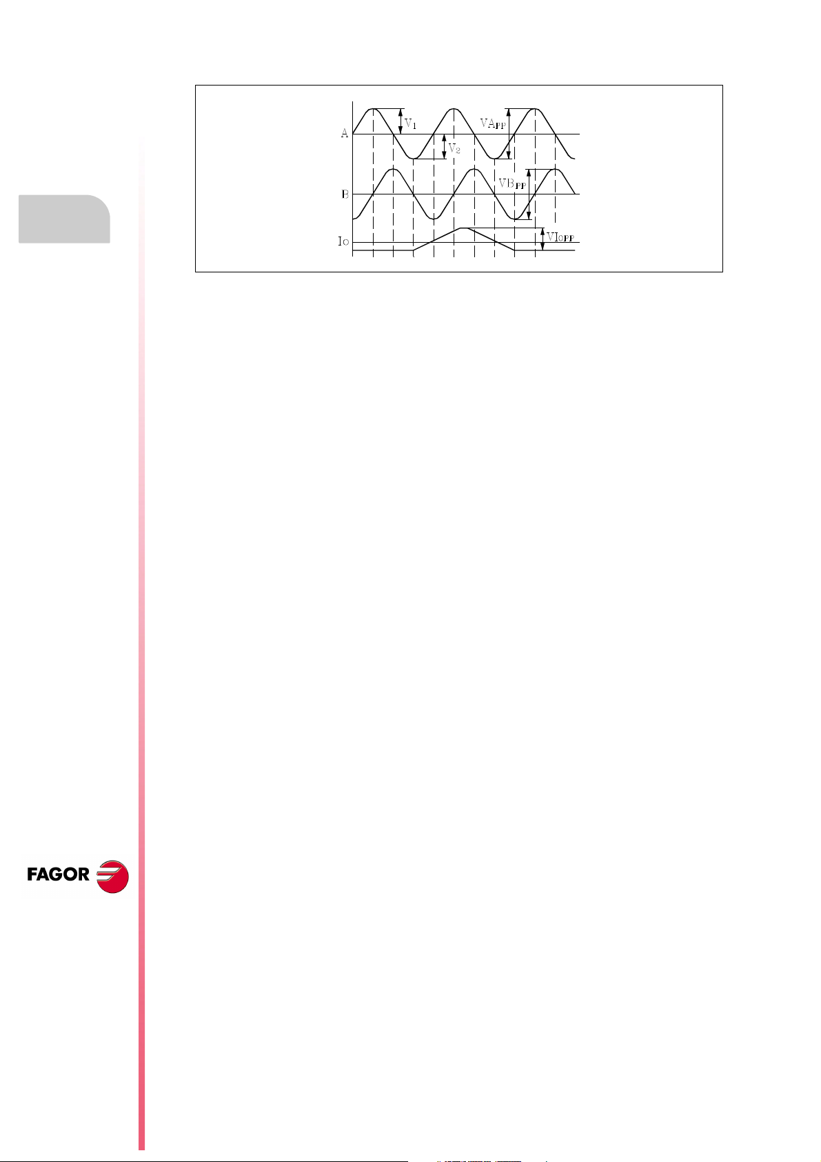
Work levels for sinusoidal signal (only for axes).
Maximum frequency 500 kHz.
A and B signals Amplitude: 0.6 ÷ 1.2 Vpp
Centered: |V1-V2| / 2 Vpp =< 6,5%
Relationship: VApp / VBpp = 0.8 ÷ 1.25
Phase shift: 90º ± 10º
Reference mark (I0) Amplitude: 0.2 ÷ 0.85 V
Width: T-90º =< I0 =< T+180º
Feedback input for the handwheels
Power supply consumption of +5 V 1 A (250 mA per axis).
Work levels for differential square signal.
Maximum frequency: 400 kHz.
Maximum gap between flanks: 460 ns.
Phase shift: 90º ± 20º.
Vmax in common mode: ± 7 V.
Vmax in differential mode: ± 6 V.
Hysteresis: 0.2 V.
Maximum differential input current: 3 mA.
Work levels for non-differential square signal.
Maximum frequency: 400 kHz.
Maximum gap between flanks: 460 ns.
Phase shift: 90º ± 20º.
High threshold (logic level "1") V
Low threshold (logic level "0") VIL:-7 V < V
Vmax: ± 7 V.
Hysteresis: 0.25 V.
Maximum differential input current: 3 mA.
:1,25 V < V
IH
IH
< 1 V.
IL
< 7 V.
CNC 8037
SOFT: V01.4X
·30·
 Loading...