

Page 1
CNC 8025 GP, M, MS
New Features (Ref. 0107 in)
Page 2

ERRORS FOUND IN THE INSTALLATION MANUAL (REF. 9707)
Appendix "F" page 10. P621(7)
It is wrong, it should say:
P621(7) The M06 function executes the M19 function (0=Yes, 1=No)
Appendix "G" page 20. P621(7)
It is wrong, it should say:
P621(7) The M06 function executes the M19 function (0=Yes, 1=No)
MODIFICATIONS TO THE INSTALLATION MANUAL (REF. 9707)
Comparison table xii. Technical description. Inputs/Outputs.
Feedback inputs for rotary axes, it should say: W (GP), W (M), W (MG), W V (MS)
Comparison table xii. Technical description. Axis control.
Electronic threading. It should say x x x
Comparison table xii. Technical description. Others. Add fields
Open loop motors without servodrives................................x
Laser machines...................................................................... x x x
JIG Grinders........................................................................... x x x
Section 3.3.3 (chapter 3 page 15). P612(6). Another example:
Having a Fagor electronic handwheel (25 lines/turn) set as follows:
P612(3) = 0 Millimeters P612(4) = 0 and P612(5) = 0 Resolution: 0.001 mm.
P612(6) = 0 Multiplication factor x4
Depending on the position of the MFO switch (Manual Feedrate Override) the selected axis will move:
Position 1 1 x 25 x 4 = 0.100 mm per turn
Position 10 10 x 25 x 4 = 1.000 mm per turn
Position 100 100 x 25 x 4 = 10.000 mm per turn
GP M MG MS
GP M MG MS
MODIFICATIONS TO THE PROGRAMMING MANUAL (REF. 9701)
Section 6.30.4 (page 128). G76 Automatic block generation
If the new program to be created is to be sent to a PC (G76 N), the DNC communication must be enabled and, at
the PC, the "program management" "Digitizing Reception" option must be selected.
If it is not, the CNC will issue error 56.
- 2 -
Page 3

Version 7.1 (July 1996)
1. EXPANSION OF THE INTEGRATED PLC RESOURCES
1.1 INPUTS
1.1.1 AXIS BEING HOMED (REFERENCED)
Input I88 indicates whether a home search is taking place and inputs I100, I101, I102, I103 and I104 indicates which axis
is being homed.
I88 Indicates whether any axis is being homed (0=No / 1=Yes)
I100 Indicates whether the X axis is being homed (0=No / 1=Yes)
I101 Indicates whether the Y axis is being homed (0=No / 1=Yes)
I102 Indicates whether the Z axis is being homed (0=No / 1=Yes)
I103 Indicates whether the W axis is being homed (0=No / 1=Yes)
I104 Indicates whether the V axis is being homed (0=No / 1=Yes)
1.1.2 AXIS MOVING DIRECTION
Inputs I42, I43, I44, I45 and I46 will show, at all times, the moving direction of each axis.
I42 Indicates the moving direction of the X axis (0=Positive / 1=negative)
I43 Indicates the moving direction of the Y axis (0=Positive / 1=negative)
I44 Indicates the moving direction of the Z axis (0=Positive / 1=negative)
I45 Indicates the moving direction of the W axis (0=Positive / 1=negative)
I46 Indicates the moving direction of the V axis (0=Positive / 1=negative)
1.2 OUTPUTS
1.2.1 ENABLING THE CYCLE-START KEY VIA PLCI
With this feature it is possible to set the treatment of the [CYCLE START] of the CNC via PLCI. Machine parameter
"P627(7)" indicates whether this feature is available or not.
P627(7) = 0 This feature is not available.
P627(7) = 1 This feature is available.
When using this feature, the way the CNC handles the [CYCLE START] key depends on the status of PLCI output O25
(CYCLE START ENABLE).
O25 = 0 The CNC ignores both the [CYCLE-START] key and the external [CYCLE-START] signal.
O25 = 1 The CNC takes into account both the [CYCLE-START] key and the external [CYCLE-START] signal.
1.2.2 TRAVEL LIMITS SET VIA PLCI
With this feature, the travel limits of the axes may be set via PLCI. Machine parameter "P627(7)" indicates whether this
feature is available or not.
P627(7) = 0 This feature is not available.
P627(7) = 1 This feature is available.
To set the travel limits for each axis, use the following outputs:
O52 / O53 Positive / negative X axis limits
O54 / O55 Positive / negative Y axis limits
O56 / O57 Positive / negative Z axis limits
O58 / O59 Positive / negative W axis limits
O60 / O61 Positive / negative V axis limits
When the PLCI activates one of this outputs while the axis is moving in the same direction, the CNC stops the axes and
the spindle and it displays an axis-travel-limit-overrun error.
- 3 -
Page 4

1.2.3 DENYING ACCESS TO THE EDITOR MODE VIA PLCI
Machine parameter "P627(7)" indicates whether this feature is available or not.
P627(7) = 0 This feature is not available.
P627(7) = 1 This feature is available.
When using this feature, access to the editor mode at the CNC depends on the status of PLCI output O26, as well as
on the current conditions (protected memory, number of the program to be locked).
O26 = 0 Free access to the editor mode (it is protected by current conditions).
O26 = 1 Denied access to the editor mode.
1.2.4 SPINDLE CONTROLLED VIA CNC OR VIA PLCI
From this version on, the spindle analog output may be set either by the CNC or by the PLCI. Machine parameter "P627(7)"
indicates whether this feature is available or not.
P627(7) = 0 This feature is not available
P627(7) = 1 This feature is available
Setting the spindle analog output via PLCI
To do this, use the combination: M1956 - R156.
Register R156 sets the spindle analog output in units of 2.442 mV. (10 / 4095)
R156 = 0000 1111 1111 1111 (R1256=4095) = 10V.
R156 = 0001 1111 1111 1111 = -10V.
R156 = 0000 0000 0000 0001 (R1256=1) = 2.5 mV.
R156 = 0001 0000 0000 0001 = -2.5 mV.
In order for the CNC to assume the value allocated to register R156, one must activate mark M1956 as described
in the PLCI Manual (section 5.5.2. Writing internal CNC variables).
Spindle controlled either by the CNC or by the PLCI
The CNC may have two internal spindle analog outputs, that of the CNC itself and the one set by the PLCI.
Use PLCI output O27 to "tell" the CNC which one of them to output.
O27 = 0 Spindle analog output set by the CNC itself.
O27 = 1 Spindle analog output set by the PLCI (combination: M1956-R156).
1.3 READING INTERNAL CNC VARIABLES
From this version on, the PLCI and the PLC64 have access to more internal CNC information.
With the PLCI, there is no need to activate a mark to access this information. The CNC itself updates this information
at the beginning of each PLCI cycle scan.
With the PLC 64, the corresponding mark must be consulted every time a CNC variable is to be checked.
The CNC information now accessible is:
Real S in rpm (REG119 at the PLCI, M1919 at the PLC64)
Not to be mistaken with R112 which indicates the programmed Spindle speed (S).
It is given in rpm and in hexadecimal format. Example: S 2487 R119= 967
Number of the block in execution (REG120 at the PLCI, M1920 at the PLC64)
It is given in hexadecimal format. Example: N120 R120= 78
Code of the last key pressed (B0-7 REG121 at the PLCI, Not available at the PLC64)
Not to be mistaken with register R118 which also indicates the code corresponding to the last key pressed, but-
When pressing a key, both registers have the same value; but the data in R121 is only kept there for one cycle
scan whereas R118 keeps its value until another key is pressed.
When pressing the same key several times, (for example: 1111):
R121 will show code "1" four times (once per cycle scan).
R118 will always show the same value, thus not being able to tell whether the "1" key has been pressed once
or more times.
The key codes are listed in the appendix of the PLCI manual.
- 4 -
Page 5
Operating mode selected at the CNC (B8-11 REG121 at the PLCI, Not available at the PLC64)
B8 B9 B10 B11
0 0 0 0 Automatic
0 0 0 1 Single block
0 0 1 0 Play-Back
0 0 1 1 Teach-in
0 1 0 0 Dry-Run
0 1 0 1 JOG
0 1 1 0 Editor
0 1 1 1 Peripherals
1 0 0 0 Tool Table and G functions
1 0 0 1 Special modes
Status of the miscellaneous "M" functions (REG122 at the PLCI, Not available at the PLC64)
The status of each one of these functions is given by a bit and will appear as a "1" when active and "0" when inactive.
B15 B14 B13 B12 B11 B10 B9 B8 B7 B6 B5 B4 B3 B2 B1 B0
M19 M1 M30 M6 M5 M4 M3 M2 M0
2. RETRACE FUNCTION.
This feature is available on the following models:
CNC-8025M CNC-8025MG CNC-8025MS
CNC-8025MI CNC-8025MGI CNC-8025MSI
Machine parameter "P627(6)" indicates whether this feature is available or not.
P627(6) = 0 This feature is not available
P627(6) = 1 This feature is available
This function may be selected by the operator. To do this, activate:
On models without PLCI: pin 7 of connector A5.
On models with PLCI: PLCI output O47
Operation:
As the CNC executes motion blocks, it always stores the last 10 blocks already executed
Whenever it executes a block containing an M,S,T type function, the machining conditions change and the CNC
deletes those previously stored motion blocks.
When the retrace function is activated, the block currently in execution is interrupted and the retrace process
begins.
First to the starting point of the current block and, then, to that of the previously stored program blocks.
If all the stored blocks are executed, the CNC stops the machine until the retrace function is canceled.
When this function is canceled, the CNC interrupts the current movement (if any) and it executes all the retraced
blocks again. Once the interruption point is reached, the CNC resumes the execution of the program.
3. OPERATION WITH TWO MOTORS AND 3 AXES.
Machine parameter "P627(8)" indicates whether this feature is available or not.
P627(8) = 0 This feature is not available.
P627(8) = 1 This feature is available.
Operation:
The CNC permits using 2 motors to move 3 axes with the following conditions:
One of the axes shared by a motor must be the Z axis and the other one must be either the X or the Y axis.
Only interpolations between the X and Y axes are possible. The Z axis cannot be interpolated with any other axis.
It must be moved alone.
Example: To move the tool from "X0 Y0 Z0" to "X20 Y20 Z20", The CNC will make this move in two steps.
First, it will move the X and Y axes to X20 Y20 and, then, the Z axis to Z20.
- 5 -
Page 6

4. SPINDLE FOLLOWING ERROR DISPLAY WHILE IN M19
From this version on, when operating with spindle orient (M19), the CNC also shows the spindle following error on the
screen corresponding to the following error in Automatic and Single block modes.
The Following Error screen shows, in large characters, the amount of axis lag and, under it, the following information
line.
F 00000.0000 & 100 S 0000 % 100 T 00.00 S 0000.000
The last value of this line "S 0000.000" shows the amount of following error (lag) of the spindle when it operates in
spindle orient mode (M19).
5. GANTRY AXES NOT MECHANICALLY SLAVED
From this version on, depending on the setting of machine parameter "P629(8)", it is possible to work with two different
types of Gantry axes.
"P629(8)=0" Mechanically slaved Gantry Axes. As until now.
When being homed, both axes behave as a single axis. The CNC takes into account only the parameter
settings and feedback pulses of the main axis, the slaved one being just a follower of the main axis,
"P629(8)=1" Not-mechanically slaved Gantry axes.
When being homed, the two axes behave as separate independent axes. First the main axis is homed
and, then, the slaved one.
6. SHEETMETAL FORMING MACHINES
This feature is available on GP models.
To enable it, set machine parameter "P626(7)=1". The CNC enables functions M98 and M99 to control the X axis
positioning loop.
Function M98 opens the X axis loop and M99 closes it.
When the CNC executes an M30, it also closes the X axis positioning loop.
When operating in jog mode, the CNC enables he following keys to control the X axis positioning loop:
Executes an M98 opening the X axis loop.
Executes an M98 opening the X axis loop.
Executes an M98 closing the X axis loop.
Version 7.2 (April 1997)
1. SCREEN SAVER
The screen saver function works as follows:
After 5 minutes without pressing a key or without the CNC refreshing the screen, the screen goes blank. Press any
key to restore the display.
Machine parameter "P626(5)" indicates whether this feature is to be used or not.
P626(5) = 0 This feature is not being used.
P626(5) = 1 This feature is being used.
2. JOGGING FEEDRATE
If while in JOG mode, the conditional input (block skip), pin 18 of connector I/O1, the CNC does not allow entering a
new F value. Only the feedrate override (%) may be varied by means of the MFO switch.
- 6 -
Page 7
3. PARAMETRIC PROGRAMMING. NEW FUNCTION: F34
Function F34 returns the number of the tool being dealt with.
P27=F34 Parameter P27 takes the value of the new tool being dealt with.
This function must be used when working with a subroutine associated with the tool change.
When using it outside that subroutine, function F34 returns the value of "100".
Version 7.3 (March 1998)
1. PLCI. Input I87
While the CNC is threading (G84), PLCI input I87 is set to “1”.
Note: Input I97 indicates rigid tapping.
Version 7.4 (May 1999)
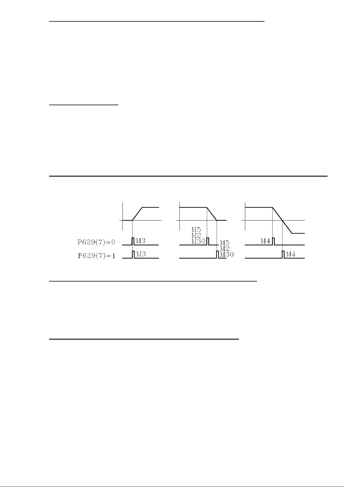
1. NEW MACHINE PARAMETER ASSOCIATED WITH THE M FUNCTIONS
Machine parameter "P629(7)" indicates when the M3, M4, M5 functions are sent out while accelerating or decelerating
the spindle.
2. CANCEL TOOL OFFSET DURING A TOOL CHANGE
From this version on, it is possible to execute a "T.0" type block inside the subroutine associated with the tool to cancel
the tool offset. This lets move to a particular position without the need for cumbersome calculations.
Only the tool offset may be canceled (T.0) or modified (T.xx). The tool cannot be changed (Txx.xx) inside the subroutine
associated with the tool.
3. DIVIDING FACTOR FOR FEEDBACK SIGNALS
Parameters P631(8), P631(7), P631(6), P631(5) and P631(4) are used together with P604(8), P604(7), P604(6), P604(5) and
P616(8) which indicate the multiplying factor to be applied to the feedback signals of the X, Y, Z, W, V axes respectively.
X axis Y axis Z axis W axis V axis
P604(8) P604(7) P604(6) P604(5) P616(8)
P631(8) P631(7) P631(6) P631(5) P631(4)
Indicate whether the feedback signals are divided (=1) or not (=0).
P631(8)=0, P631(7)=0, P631(6)=0, P631(5)=0 and P631(4)=0 They are not divided
P631(8)=1, P631(7)=1, P631(6)=1, P631(5)=1 and P631(4)=1 They are divided by two.
Example:
We wish to obtain a resolution of 0.01 mm with a squarewave encoders mounted on the X axis with 5mm pitch ballscrew
Nr of pulses = ballscrew pitch / (Multiplying factor x Resolution)
With P604(8)=0 & P631(8)=0 x4 multiplying factor Nr of pulses = 125
With P604(8)=1 & P631(8)=0 x2 multiplying factor Nr of pulses = 250
With P604(8)=0 & P631(8)=1 x2 multiplying factor Nr of pulses = 250
With P604(8)=1 & P631(8)=1 x1 multiplying factor Nr of pulses = 500
- 7 -
Page 8

Version 7.6 (July 2001)
1. G75 AFFECTED BY FEEDRATE OVERRIDE
From this version on, there is a new machine parameter indicating whether G75 is affected by the feedrate override or
not.
P631(1) = 0 Not affected. It is always at 100%, like in previous versions.
P631(1) = 1 It is affected by the Feedrate override.
2. FEEDBACK FACTOR.
From this version on, there is a new machine parameter to set the resolution of an axis having an encoder and a leadscrew.
P819 Feedback factor for the X axis P820 Feedback factor for the Y axis P821 Feedback factor for the Z axis
P822 Feedback factor for the W axis P823 Feedback factor for the V axis
Values between 0 and 65534. The “0” value indicates that this feature is not being used.
Use the following formula to calculate the “Feedback Factor” :
Feedback factor = (Gear Ratio x Leadscrew pitch / Number of Encoder pulses) x 8.192
Examples: Gear Ratio 1 1 2 1
Leadscrew pitch 5000 6000 6000 8000 (microns)
Encoder 2500 2500 2500 2500 (pulses/turn)
Feedback factor 16384 19660.8 39321.6 26214.4
The machine parameters only admit integer values and sometimes the “Feedback Factor” has decimals. In those cases,
assign the integer part to the machine parameter and use the leadscrew compensation table to make up for the decimal
part.
The values to be entered in the table are calculated with the following formula:
Leadscrew position = Leadscrew Error (microns) x Integer of feedback factor / decimals of the feedback factor
For example: Gear ratio = 1 Leadscrew pitch = 6000 Encoder = 2500
Feedback factor = 19660.8 Machine parameter = 19660
For a leadscrew error of 20 microns Leadscrew position = 20 x 19660 / 0.8 = 491520
Going on with the calculation, we come up with the following table.
Leadscrew position Leadscrew error
P0 = -1966.000 P1 = -0.080
P2 = -1474.500 P3 = -0.060
P4 = -983.000 P5 = -0.040
P6 = -491.500 P7 = -0.020
P8 = 0 P9 = 0
P10 = 491.500 P11 = 0.020
P12 = 983.000 P13 = 0.040
P14 = 1472.500 P15 = 0.060
P16 = 1966.000 P17 = 0.080
3. NEW MODEL
From this version on, the new model MLI is now available.
It offers the same features as the MGI model and it is sold together with the motors and ACS drives..
Headquarters (SPAIN): Fagor Automation S. Coop.
Bº San Andrés s/n, Apdo. 144
20500 Arrasate - Mondragón
Tel: +34-943-719200
Fax: +34- 943-791712
+34-943-771118 (Service Dept.)
www.fagorautomation.com
E-mail: info@fagorautomation.es
- 8 -
Page 9

FAGOR 8025/8030 CNC
Models: M, MG, MS, GP
OPERATING MANUAL
Ref. 9701 (in)
Page 10

ABOUT THE INFORMATION IN THIS MANUAL
This manual is addressed to the machine operator. It describes how to operate with this 8025
CNC.
It includes the necessary information for new users as well as advanced subjects for those who
are already familiar with this CNC product.
It may not be necessary to read this whole manual. Consult the list of "New Features and
Modifications" which will indicate to you the chapters and sections describing them.
Consult the Comparison Table in order to find the specific features offered by your particular
CNC model.
There is also an appendix on error codes which indicates some of the probable reasons which
could cause each one of them.
Notes:
The information described in this manual may be subject to variations due to
technical modifications.
FAGOR AUTOMATION, S.Coop. Ltda. reserves the right to modify the contents
of the manual without prior notice.
Page 11

INDEX
Section Page
Comparison table for Mill Model FAGOR 8025/8030 CNCs .........................................ix
New features and modifications ......................................................................................xv
INTRODUCTION
Safety Conditions ...........................................................................................................Intr. 3
Material Returning Terms ............................................................................................. Intr. 5
Fagor Documentation for the 8025/30 M CNC ..........................................................Intr. 6
Manual Contents ............................................................................................................Intr. 7
1. Overview..........................................................................................................................1
2. Front panel 8025/30 CNC............................................................................................... 2
2.1. Monitor/keyboard for the 8030 CNC .............................................................................2
2.2. Control panel for the 8030 CNC .....................................................................................4
2.3. Monitor/keyboard/control panel for the 8025 CNC ......................................................5
2.4. Selection of colors ...........................................................................................................7
2.5. Cancellation of monitor display .....................................................................................7
2.6. Function keys (soft keys) ................................................................................................7
3. OPERATING MODES .....................................................................................................8
3.1. 0 mode: AUTOMATIC (Continuous cycle) / 1 mode: SINGLE BLOCK .......................10
3.1.1. Execution of a program ...................................................................................................10
3.1.1.1. Selection of the Automatic (0) Single Block (1) operating modes ...............................10
3.1.1.2. Selection of the program to be executed ........................................................................ 10
3.1.1.3. Selection of the first block to be executed .....................................................................11
3.1.1.4. Display of the contents of the blocks ............................................................................. 11
3.1.1.5. Cycle Start .......................................................................................................................12
3.1.1.6. Cycle Stop .......................................................................................................................12
3.1.1.7. Changing the operating mode ........................................................................................13
3.1.2. Display modes .................................................................................................................13
3.1.2.1. Selection of the display mode ........................................................................................ 13
3.1.2.2. Standard display mode ....................................................................................................14
3.1.2.3. Current position display mode .......................................................................................15
3.1.2.4. Following error display mode .........................................................................................15
3.1.2.5. Arithmetic parameters display mode ..............................................................................15
3.1.2.6. Subroutine status, clock and parts counter display mode ..............................................16
3.1.2.7. Graphics display mode ....................................................................................................17
3.1.3. Programming while running a program. Background ....................................................18
3.1.4. PLC/LAN mode ...............................................................................................................18
3.1.5. Verification and modification of the values of the tool offset table
without stopping the cycle ............................................................................................. 19
3.1.6. Tool inspection ............................................................................................................... 19
3.1.7. CNC reset ........................................................................................................................21
3.1.8. Display and deletion of the Messages sent by the FAGOR PLC 64...............................21
3.2. Mode 2: PLAY-BACK .................................................................................................... 22
3.2.1 Selection of the operating mode PLAY-BACK ..............................................................22
Page 12

Section Page
3.2.2. Locking/Unlocking of memory ......................................................................................22
3.2.3. Deletion of a complete program......................................................................................22
3.2.4. Change of program number............................................................................................. 22
3.2.5. Display and search of memorized subroutines ...............................................................22
3.2.6. Selection of a program ....................................................................................................22
3.2.7. Creating a program..........................................................................................................23
3.2.8. Deletion of a block..........................................................................................................23
3.2.9. Copy a program ...............................................................................................................23
3.3. MODE 3: TEACH-IN....................................................................................................... 24
3.3.1. Selection of the operating mode TEACH-IN ..................................................................24
3.3.2. Locking/Unlocking of memory .......................................................................................24
3.3.3. Deletion of a complete program ......................................................................................24
3.3.4. Change of program number ............................................................................................ 24
3.3.5. Display and search of memorized subroutines ............................................................... 24
3.3.6. Selection of a program ....................................................................................................24
3.3.7. Program creation .............................................................................................................25
3.3.8. Deletion of a block ..........................................................................................................25
3.3.9. Copy a program ...............................................................................................................25
3.4. Mode 4: DRY RUN.........................................................................................................26
3.4.1. Execution of a program ...................................................................................................26
3.4.1.1. Selection of the operating mode DRY RUN (4) .............................................................26
3.4.1.1.1. Selection of execution mode ...........................................................................................28
3.4.1.2. Selection of the program to be executed......................................................................... 29
3.4.1.3. Selection of starting block...............................................................................................29
3.4.1.4. Display of the contents of the blocks ..............................................................................29
3.4.1.5. Cycle Start .......................................................................................................................29
3.4.1.6. Cycle Stop ....................................................................................................................... 29
3.4.1.7. Change of operating mode ..............................................................................................29
3.4.1.8. Tool inspection................................................................................................................30
3.4.2. Display modes .................................................................................................................30
3.5. Mode 5: JOG ...................................................................................................................31
3.5.1. Selection of the JOG operating mode .............................................................................31
3.5.2. Search for machine reference axis by axis ......................................................................32
3.5.3. Presetting a coordinate value ..........................................................................................32
3.5.4. Jogging the axes ..............................................................................................................33
3.5.4.1. Continuous movement ..................................................................................................... 33
3.5.4.2. Incremental movement.................................................................................................... 34
3.5.5. Entering F,S and M ......................................................................................................... 34
3.5.5.1. Entering an F value .........................................................................................................34
3.5.5.2. Entering an S value .........................................................................................................35
3.5.5.3. Entering an M value ........................................................................................................35
3.5.6. Operation of the CNC as a readout .................................................................................35
3.5.7. Change of measurement units.........................................................................................36
3.5.8. Handwheel operation.......................................................................................................36
3.5.9. Display/Modification of RANDOM table.......................................................................37
3.5.10. Measuring and loading of tool offsets with a probe ....................................................... 40
3.5.11. Spindle operating keys ....................................................................................................41
3.6. Mode 6: EDITING ..........................................................................................................42
3.6.1. Selection of the operating mode EDITING(6) ................................................................42
3.6.2. Locking/Unlocking of memory and formatting of 512 Kb memory ..............................42
3.6.3. Part-program directory .................................................................................................... 43
3.6.3.1. Deletion of a complete program......................................................................................43
3.6.4. Change of program number ............................................................................................ 44
3.6.5. Display and search of subroutines stored in memory .....................................................44
3.6.6. Selection of a program ....................................................................................................45
3.6.7. Creating a program ..........................................................................................................45
3.6.7.1 Displaying the block contents .........................................................................................45
3.6.7.2. Unassisted programming.................................................................................................46
3.6.7.3. Modification and deletion of a block ..............................................................................47
3.6.7.4. Assisted programming ..................................................................................................... 48
Page 13

Section Page
3.6.7.5. Save a program being edited (only on models with 512 Kb of memory) .......................49
3.6.7.6. Copying a program..........................................................................................................49
3.7. Mode 7: PERIPHERALS ................................................................................................50
3.7.1. Selection of the operating mode PERIPHERALS (7).....................................................50
3.7.2. Entering a program from the FAGOR cassette/recorder (0) ...........................................51
3.7.2.1. Transmission errors ......................................................................................................... 53
3.7.3. Transferring a program to the FAGOR cassette recorder (1)...........................................53
3.7.3.1. Transmission errors ......................................................................................................... 54
3.7.4. Entering a program from a peripheral other than the FAGOR cassette/recorder (2) .....55
3.7.5. Transferring a program to a peripheral other than the FAGOR cassette/recorder (3) ....55
3.7.6. FAGOR cassette’s directory (4) ......................................................................................56
3.7.7. Deletion of a FAGOR cassette program (5) ....................................................................56
3.7.8. Interruption of the transmission process .........................................................................57
3.7.9. DNC. Communication with a computer..........................................................................57
3.8. Mode 8: TOOL OFFSETS AND ZERO OFFSETS G53/G59 ........................................58
3.8.1. Selection of the operating mode TOOL OFFSET (8) .....................................................58
3.8.2. Read-out of tool table ......................................................................................................58
3.8.3. Entering the dimensions of the tools ...............................................................................59
3.8.4. Modification of tool dimensions .....................................................................................59
3.8.5. Change of measurement units .........................................................................................60
3.8.6. Zero offsets ......................................................................................................................61
3.8.6.1. Displaying the zero offset table ....................................................................................... 61
3.8.6.2. Entering zero offset values..............................................................................................61
3.8.6.3. Modification of zero offset values ..................................................................................62
3.8.6.4. Change of measuring units.............................................................................................. 62
3.8.7. Return to the tool offset table ..........................................................................................62
3.8.8. Complete deletion of tool offsets or zero table ...............................................................62
3.9. Mode 9: SPECIAL MODES ...........................................................................................62
3.10. Graphics...........................................................................................................................63
3.10.1. Display area definition ....................................................................................................64
3.10.2. Zooming (windowing) ....................................................................................................65
3.10.3. Redefinition of the display area by the Zoom function ..................................................66
3.10.4. Deletion of graphics ........................................................................................................66
3.10.5. Graphic representation in color ......................................................................................66
ERROR CODES
Page 14
COMPARISON TABLE
FOR MILL MODEL
FAGOR 8025/8030 CNCs
Page 15
8025/8030 MILL MODEL CNCS
Fagor offers the 8025 and 8030 mill type CNCs.
Both types operate the same way and offer similar characteristics. Their basic difference is that
the former is compact and the latter is modular.
Both CNC types offer basic models. Although the differences between the basic models are
detailed later on, each model may be defined as follows:
8025/8030 GP Oriented to General Purpose machines
8025/8030 M Oriented to Milling machines of up to 4 axes.
8025/8030 MG Same as the M model, but with dynamic graphics.
8025/8030 MS Oriented to Machining Centers (up to 5 axes).
When the CNC has an Integrated Programmable Logic Controller (PLCI), the letter "I" is added
to the CNC model denomination: GPI, MI, MGI, MSI.
Also, When the CNC has 512Kb of part-program memory, the letter "K" is added to the CNC
model denomination: GPK, MK, MGK, MSK, GPIK, MIK, MGIK, MSIK.
Basic With PLCI Basic With PLCI
With 512Kb and 512Kb
General Purpose GP GPI GPK GPKI
Mills up to 4 axes M MI MK MIK
Up to 4 axes with graphics MG MGI MGK MGIK
Machining Centers MS MSI MSK MSIK
Page 16
TECHNICAL DESCRIPTION
GP M MG MS
INPUTS/OUTPUTS
Feedback inputs......................................................................................... 6 6 6 6
Probe input ............................................................................................. x x x x
Square-wave feedback signal multiplying factor, x2/x4 ........................... x x x x
Sine-wave feedback signal multiplying factor, x2/x4/10/x20 ................... x x x x
Maximum counting resolution 0.001mm/0.001°/0.0001inch.................... x x x x
Analog outputs (±10V) for axis servo drives ............................................ 4 4 4 5
Spindle analog output (±10V) ................................................................... 1 1 1 1
AXIS CONTROL
Axes involved in linear interpolations....................................................... 3 3 3 3
Axes involved in circular interpolations.................................................... 2 2 2 2
Helical interpolation .................................................................................. x x x x
Electronic threading .................................................................................. x x x
Spindle control .......................................................................................... x x x x
Software travel limits ................................................................................ x x x x
Spindle orientation .................................................................................... x x x x
Management of non-servo-controlled Open-Loop motor ......................... x
PROGRAMMING
Part Zero preset by user............................................................................. x x x x
Absolute/incremental programming .......................................................... x x x x
Programming in cartesian coordinates ...................................................... x x x x
Programming in polar coordinates ............................................................ x x x x
Programming in cylindrical coordinates (radius, angle, axis) ................... x x x x
Programming by angle and cartesian coordinate....................................... x x x x
Linear axes ........................................................................... 4 4 4 5
Rotary axes........................................................................... 2 2 2 2
Spindle encoder.................................................................... 1 1 1 1
Electronic handwheels ......................................................... 1 1 1 1
COMPENSATION
Tool radius compensation ......................................................................... x x x
Tool length compensation ......................................................................... x x x x
Leadscrew backlash compensation............................................................ x x x x
Leadscrew error compensation.................................................................. x x x x
Cross compensation (beam sag) ................................................................ x x x x
DISPLAY
CNC text in Spanish, English, French, German and Italian ...................... x x x x
Display of execution time.......................................................................... x x x x
Piece counter ............................................................................................. x x x x
Graphic movement display and part simulation ........................................ x x
Tool base position display ......................................................................... x x x x
Tool tip position display............................................................................ x x x x
Geometric programming aide.................................................................... x x x x
COMMUNICATION WITH OTHER DEVICES
Communication vía RS232C ..................................................................... x x x x
Communication via DNC .......................................................................... x x x x
Communication via RS485 (FAGOR LAN) ............................................. x x x x
ISO program loading from peripherals...................................................... x x x x
OTHERS
Parametric programming ........................................................................... x x x x
Model digitizing ........................................................................................ x x x x
Possibility of an integrated PLC ................................................................ x x x x
Sheetmetal tracing on LASER machines................................................... x
Jig Grinder ............................................................................................. x
Page 17
PREPARATORY FUNCTIONS
GP M MG MS
AXES AND COORDINATE SYSTEMS
XY (G17) plane selection........................................................................... x x x x
XZ and YZ plane selection (G18,G19) ...................................................... x x x x
Part measuring units. Millimeters or inches (G70,G71)............................. x x x x
Absolute/incremental programming (G90,G91) ........................................ x x x x
Independent axis (G65) .............................................................................. x x x x
REFERENCE SYSTEMS
Machine reference (home) search (G74).................................................... x x x x
Coordinate preset (G92) ............................................................................. x x x x
Zero offsets (G53...G59) ............................................................................ x x x x
Polar origin preset (G93) ............................................................................ x x x x
Store current part zero (G31)...................................................................... x x x x
Recover stored part zero (G32) ................................................................. x x x x
PREPARATORY FUNCTIONS
Feedrate F .............................................................................................. x x x x
Feedrate in mm/min. or inches/minute (G94) ............................................ x x x x
Feedrate in mm/revolution or inches/revolution (G95) .............................. x x x x
Constant surface speed (G96)..................................................................... x x x x
Constant tool center speed (G97) ............................................................... x x x x
Programmable feedrate override (G49)...................................................... x x x x
Spindle speed (S)........................................................................................ x x x x
S value limit (G92) ..................................................................................... x x x x
Tool and tool offset selection (T) ............................................................... x x x x
AUXILIARY FUNCTIONS
Program stop (M00) ................................................................................... x x x x
Conditional program stop (M01)................................................................ x x x x
End of program (M02) ............................................................................... x x x x
End of program with return to first block (M30) ....................................... x x x x
Clockwise spindle start (M03).................................................................... x x x x
Counter-clockwise spindle start (M04) ...................................................... x x x x
Spindle stop (M05)..................................................................................... x x x x
Tool change in machining centers (M06)................................................... x x x x
Spindle orientation (M19) .......................................................................... x x x x
Spindle speed range change (M41, M42, M43, M44)................................ x x x x
Functions associated with pallets (M22, M23, M24, M25)........................ x x x
PATH CONTROL
Rapid traverse (G00) ................................................................................x x x x
Linear interpolation (G01)........................................................................x x x x
Circular interpolation (G02,G03) .............................................................x x x x
Circular interpolation with absolute center coordinates (G06).................x x x x
Circular path tangent to previous path (G08) ...........................................x x x x
Arc defined by three points (G09)............................................................x x x x
Tangential entry at beginning of a machining operation (G37) ..............x x x x
Tangential exit at the end of a machining operation (G38) ......................x x x x
Controlled radius blend (G36)..................................................................x x x x
Chamfer (G39) .........................................................................................x x x x
Electronic threading (G33) ......................................................................... x x x
ADDITIONAL PREPARATORY FUNCTIONS
Dwell (G04 K)..........................................................................................x x x x
Round and square corner (G05, G07) ......................................................x x x x
Mirror image (G10,G11,G12) ..................................................................x x x x
Mirror image along the Z axis (G13) .......................................................x x x x
Scaling factor (G72) .................................................................................x x x x
Pattern rotation (G73)...............................................................................x x x x
Slaving/unslaving of axes (G77, G78) .....................................................x x x x
Single block treatment (G47, G48) ..........................................................x x x x
User error display (G30)...........................................................................x x x x
Automatic block generation (G76)............................................................. x
Communication with FAGOR Local Area Network (G52)......................x x x x
Page 18
GP M MG MS
COMPENSATION
Tool radius compensation (G40,G41,G42) .............................................. x x x
Tool length compensation (G43,G44) ...................................................... x x x x
Loading of tool dimensions into internal tool table (G50) ....................... x x x x
CANNED CYCLES
Multiple arc-pattern machining (G64)...................................................... x x x
User defined canned cycle (G79) ............................................................. x x x x
Drilling cycle (G81) ................................................................................. x x x
Drilling cycle with dwell (G82)................................................................ x x x
Deep hole drilling cycle (G83) ................................................................. x x x
Tapping cycle (G84)................................................................................. x x x
Rigid tapping cycle (G84R)...................................................................... x x x
Reaming cycle (G85)................................................................................ x x x
Boring cycle with withdrawal in G00 (G86) ............................................ x x x
Rectangular pocket milling cycle (G87)................................................... x x x
Circular pocket milling cycle (G88) ......................................................... x x x
Boring cycle with withdrawal in G01 (G89) ............................................ x x x
Canned cycle cancellation (G80).............................................................. x x x x
Return to starting point (G98) .................................................................. x x x
Return to reference plane (G99) ............................................................... x x x
PROBING
Probing (G75)........................................................................................... x x x x
Tool length calibration canned cycle (G75N0) ........................................ x
Probe calibration canned cycle (G75N1).................................................. x
Surface measuring canned cycle (G75N2) ............................................... x
Surface measuring canned cycle with tool offset (G75N3) ...................... x
Outside edge measuring canned cycle (G75N4) ...................................... x
Inside edge measuring canned cycle (G75N5) ......................................... x
Angle measuring canned cycle (G75N6).................................................. x
Outside edge and angle measuring canned cycle (G75N7) ...................... x
Hole centering canned cycle (G75N8) ..................................................... x
Boss centering canned cycle (G75N9) ..................................................... x
Hole measuring canned cycle (G75N10).................................................. x
Boss measuring canned cycle (G75N11).................................................. x
SUBROUTINES
Number of standard subroutines............................................................... 99 99 99 99
Definition of standard subroutine (G22) .................................................. x x x x
Call to a standard subroutine (G20).......................................................... x x x x
Number of parametric subroutines ........................................................... 99 99 99 99
Definition of parametric subroutine (G23) ............................................... x x x x
Call to a parametric subroutine (G21) ..................................................... x x x x
End of standard or parametric subroutine (G24) ...................................... x x x x
JUMP OR CALL FUNCTIONS
Unconditional jump/call (G25)................................................................. x x x x
Jump or call if zero (G26) ........................................................................ x x x x
Jump or call if not zero (G27) .................................................................. x x x x
Jump or call if smaller (G28).................................................................... x x x x
Jump or call if equal or greater (G29) ...................................................... x x x x
Page 19
NEW FEATURES
AND
MODIFICATIONS
Date: February 1991 Software version: 2.1 and newer
FEATURE MODIFIED MANUAL AND SECTION
Error 65 is not issued while probing (G75) Installation Manual Section 3.3.4
It is possible to select the home searching Installation Manual Section 4.6
direction for each axis
New 1, 2, 5, 10 resolution values for Installation Manual Section 4.1
sine-wave feedback signals of each axis
PLCI register access from the CNC Programming Manual G52
Sheetmetal tracing on laser machines Applications Manual
Jig Grinder Applications Manual
Date: June 1991 Software version: 3.1 and newer
FEATURE MODIFIED MANUAL AND SECTION
Repetitive emergency subroutine Installation Manual Section 3.3.8
New function F29. It takes the value of the Programming Manual Chapter 13
selected tool
Function M06 does not execute M19 Installation Manual Section 3.3.5
Greater speed when executing several
parametric blocks in a row.
Page 20
Date: March 1992 Software version: 4.1 and newer
FEATURE MODIFIED MANUAL AND SECTION
Bell-shape acceleration/deceleration control Installation Manual Section 4.7
Expansion of cross compensation Installation Manual Section 4.10
Rigid Tapping G84 R Programming Manual G84
Possibility to enter the sign of the leadscrew Installation Manual Section 4.9
backlash for each axis
Independent execution of an axis Programming Manual G65
Date: July 1993 Software version: 5.1 and newer
FEATURE MODIFIED MANUAL AND SECTION
Double cross compensation Installation Manual Section 4.10
Linear and bell-shaped acc./dec. ramp Installation Manual Section 4.7
combination for the axes
Acceleration/deceleration control for the Installation Manual Section 5.
the spindle
Multiple arc pattern machining Programming Manual G64
Tool tip position display Installation Manual Section 3.3.5
The associated subroutine is executed before Installation Manual Section 3.3.5
the T function
The additional circular sections of a Installation Manual Section 3.3.8
compensated path are executed in G05 or G07
VGA monitor 8030 CNC. Installation Manual Chapter 1
Page 21
Date: March 1995 Software version: 5.3 and newer
FEATURE MODIFIED MANUAL AND SECTION
Management of feedback with coded Io Installation Manual Section 4.6 & 6.5
Spindle inhibit by PLC Installation Manual Section 3.3.9
Handwheel management by PLC Installation Manual Section 3.3.3
Rapid (JOG) key simulation via PLC PLCI Manual
Non-servo-controlled open-loop motors Applications Manual
Function G64, multiple machining in an arc. Installation Manual Section 3.3.9
To be selected by machine parameter.
Initialization of machine parameters after
memory loss.
Date: September 1995 Software version: 6.0 and newer
FEATURE MODIFIED MANUAL AND SECTION
512 Kb of part-program memory Operating Manual Section 3.6
When conditional input (block skip) active
while in JOG mode, the
key is ignored Installation Manual Section 1.3.6
Page 22

INTRODUCTION
Introduction - 1
Page 23

SAFETY CONDITIONS
Read the following safety measures in order to prevent damage to personnel, to
this product and to those products connected to it.
This unit must only be repaired by personnel authorized by Fagor Automation.
Fagor Automation shall not be held responsible for any physical or material
damage derived from the violation of these basic safety regulations.
Precautions against personal damage
Before powering the unit up, make sure that it is connected to ground
In order to avoid electrical discharges, make sure that all the grounding connections
are properly made.
Do not work in humid environments
In order to avoid electrical discharges, always work under 90% of relative humidity
(non-condensing) and 45º C (113º F).
Do not work in explosive environments
In order to avoid risks, damage, do not work in explosive environments.
Precautions against product damage
Working environment
This unit is ready to be used in Industrial Environments complying with the directives
and regulations effective in the European Community
Fagor Automation shall not be held responsible for any damage suffered or caused
when installed in other environments (residential or homes).
Install the unit in the right place
It is recommended, whenever possible, to instal the CNC away from coolants,
chemical product, blows, etc. that could damage it.
This unit complies with the European directives on electromagnetic compatibility.
Nevertheless, it is recommended to keep it away from sources of electromagnetic
disturbance such as.
- Powerful loads connected to the same AC power line as this equipment.
- Nearby portable transmitters (Radio-telephones, Ham radio transmitters).
- Nearby radio / TC transmitters.
- Nearby arc welding machines
- Nearby High Voltage power lines
- Etc.
Ambient conditions
The working temperature must be between +5° C and +45° C (41ºF and 113º F)
The storage temperature must be between -25° C and 70° C. (-13º F and 158º F)
Introduction - 3
Page 24
Protections of the unit itself
Central Unit
It carries two fast fuses of 3.15 Amp./ 250V. to protect the mains AC input.
All the digital inputs and outputs are protected by an external fast fuse (F) of 3.15
Amp./ 250V. against over voltage and reverse connection of the power supply.
Monitor
The type of fuse depends on the type of monitor. See the identification label of the
unit.
Precautions during repair
Do not manipulate the inside of the unit
Only personnel authorized by Fagor Automation may manipulate the
inside of this unit.
Do not manipulate the connectors with the unit connected to AC
power.
Before manipulating the connectors (inputs/outputs, feedback, etc.)
make sure that the unit is not connected to AC power.
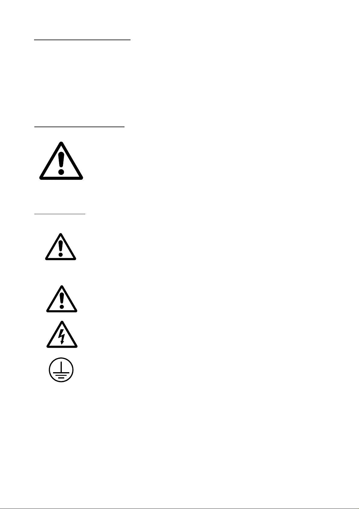
Safety symbols
Symbols which may appear on the manual
WARNING. symbol
It has an associated text indicating those actions or operations may hurt
people or damage products.
Symbols that may be carried on the product
WARNING. symbol
It has an associated text indicating those actions or operations may hurt
people or damage products.
"Electrical Shock" symbol
It indicates that point may be under electrical voltage
"Ground Protection" symbol
It indicates that point must be connected to the main ground point of the
machine as protection for people and units.
Introduction - 4
Page 25

MATERIAL RETURNING TERMS
When returning the CNC, pack it in its original package and with its original packaging
material. If not available, pack it as follows:
1.- Get a cardboard box whose three inside dimensions are at least 15 cm (6 inches) larger
than those of the unit. The cardboard being used to make the box must have a
resistance of 170 Kg (375 lb.).
2.- When sending it to a Fagor Automation office for repair, attach a label indicating the
owner of the unit, person to contact, type of unit, serial number, symptom and a brief
description of the problem.
3.- Wrap the unit in a polyethylene roll or similar material to protect it.
When sending the monitor, especially protect the CRT glass.
4.- Pad the unit inside the cardboard box with poly-utherane foam on all sides.
5.- Seal the cardboard box with packing tape or industrial staples.
Introduction - 5
Page 26

FAGOR DOCUMENTATION
FOR THE 8025/30 M CNC
8025M CNC OEM Manual Is directed to the machine builder or person in charge of installing and starting
8025M CNC USER Manual Is directed to the end user or CNC operator.
DNC 25/30 Software Manual Is directed to people using the optional DNC communications software.
DNC 25/30 Protocol Manual Is directed to people wishing to design their own DNC communications
PLCI Manual To be used when the CNC has an integrated PLC.
up the CNC.
It contains 2 manuals:
Installation Manual describing how to isntall and set-up the CNC.
LAN Manual describing how to instal the CNC in the Local
Area Network.
Sometimes, it may contain an additional manual describing New Software
Features recently implemented.
It contains 3 manuals:
Operating Manual describing how to operate the CNC.
Programming Manual describing how to program the CNC.
Applications Manual describing other applications for this CNC
non-specific of Milling machines
Sometimes, it may contain an additional manual describing New Software
Features recently implemented.
software to communicate with the 800 without using the DNC25/30 software..
Is directed to the machine builder or person in charge of installing and starting
up the PLCI.
DNC-PLC Manual Is directed to people using the optional communications software: DNC-PLC.
FLOPPY DISK Manual Is directed to people using the Fagor Floppy Disk Unit and it shows how to use
it.
Introduction - 6
Page 27

MANUAL CONTENTS
The operating manual consists of the following chapters:
Index
Comparison table of FAGOR models: 8025 M CNCs
New Features and modifications.
Introduction Safety conditions.
Material returning conditions.
FAGOR documentation for the 8025 M CNC.
Manual contents.
Overview
Front panel of the 8025 M CNC
Operating modes
0- Automatic
1- Single block
2- Play-back
3- Teach-in
4- Dry-run
5- Jog
6- Editor
7- Peripheral
8- Tool table and zero offset table
9- Special modes
Error codes
Introduction - 7
Page 28

1. OVERVIEW
This manual contains the information required for the proper operation of the CNC.
It describes the controls fitted on both the keyboard and the front panel.
Also the CNC operating modes and the information displayed on the screen are explained.
8025/8030 CNC OPERATING MANUAL 1
Page 29
2. FRONT PANEL 8025/30 CNC
2.1. MONITOR/KEYBOARD FOR THE 8030 CNC
1. Function keys (SOFT-KEYS)
2. Alphanumeric keyboard for editing programs.
3. ENTER. Allows information to be entered in the CNC memory, etc.
4. RECALL. To access a program, a block within a program,etc.
5. OP MODE. Allows a list of operating modes to be displayed on the screen. It is a
previous step to accessing any of them.
6. DELETE. It allows deletion of a complete program or a block of the programme.
Deletion of the graphic representation, etc.
2 8025/8030 CNC OPERATING MANUAL
Page 30

7. RESET. To revert the CNC to the initial conditions and recognise new machine
parameter values, decoded M functions, etc.
8. CL. To delete characters one by one during the editing process, etc.
9. INS. Key which allows characters to be inserted during the edition of a program block.
10. Arrow keys for moving cursor.
11. Page up and page down keys.
12. SP. Reserves a space between characters of a comment.
CAPS. Allows characters to be edited in capitals.
SHIFT. Allows characters to be edited which are found on keys with double meaning.
8025/8030 CNC OPERATING MANUAL 3
Page 31

2.2. CONTROL PANEL FOR THE 8030 CNC
1. Emergency Button or Electronic Handwheel (optional)
2. JOG keys for manual displacement of the axes.
3. RAPID FEED button.
4. Switch (M.F.O.), which allows a % variation of the programmed feedrate and to choose
the different ways of working in the JOG MODE (continuous, incremental, electronic
handwheel).
5. Spindle operating keys. Allow the spindle to be put into OPERATION and to STOP
it, in the JOG operating mode. The and keys allow a % variation of the
programmed turning speed of the spindle during operation.
6. START. Cycle START key.
7. STOP. Cycle STOP key.
4 8025/8030 CNC OPERATING MANUAL
Page 32

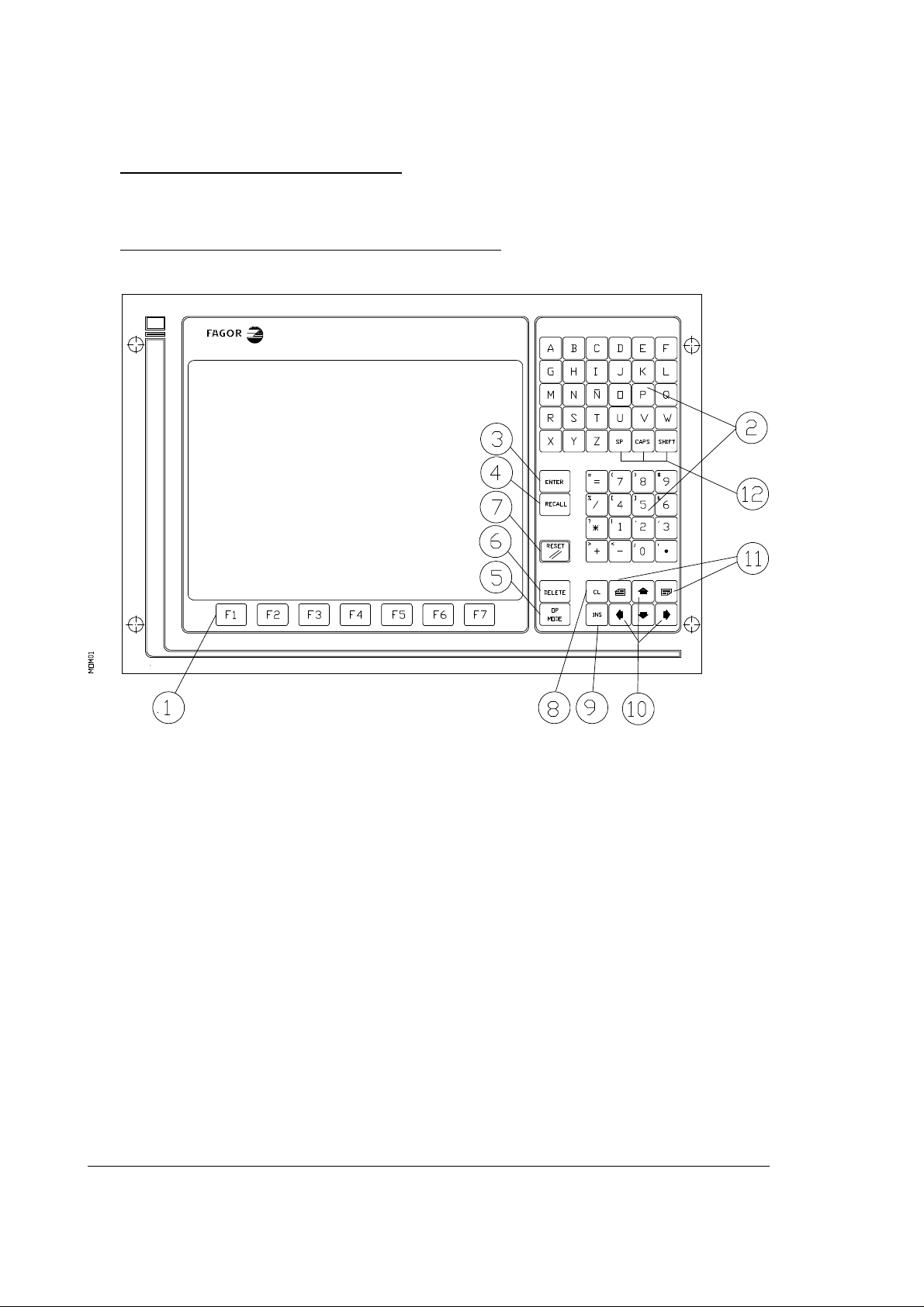
2.3. MONITOR/KEYBOARD/CONTROL PANEL FOR THE 8025 CNC
1. Function keys (SOFT-KEYS)
2. Alphanumeric keyboard for editing programs.
3. ENTER. Allows information to be entered in the CNC memory, etc.
4. RECALL. To access a program, a block within a program,etc.
5. OP MODE. Allows a list of operating modes to be displayed on the screen. It is a previous
step to accessing any of them.
6. DELETE. It allows deletion of a complete program or a block of the programme. Deletion
of the graphic representation, etc.
7. RESET. To revert the CNC to the initial conditions and recognise new machine parameter
values, decoded M functions, etc.
8025/8030 CNC OPERATING MANUAL 5
Page 33

8. CL. To delete characters one by one during the editing process, etc.
9. INS. Key which allows characters to be inserted during the edition of a program block.
10. Arrow keys for moving the cursor.
11. Page up and page down keys.
12. SP. Reserves a space between characters of a comment.
CAPS. Allows characters to be edited in capitals.
SHIFT. Allows characters to be edited which are found on keys with double meaning.
13. JOG keys for manual displacement of the axes.
14. RAPID FEED button.
15. Switch (M.F.O.), which allows a % variation of the programmed feed and to choose the
different ways of working in the JOG MODE (continuous, incremental, electronic
handwheel).
16. Spindle operating keys. Allow the spindle to be put into OPERATION and to STOP it,
in the JOG operating mode. The and keys allow a % variation of the programmed
turning speed of the spindle during operation.
17. START. Cycle START key.
18. STOP. Cycle STOP key.
6 8025/8030 CNC OPERATING MANUAL
Page 34

2.4. SELECTION OF COLORS
Whenever the CNC is fitted with a COLOR MONITOR, it is possible to choose the set of colors
one wishes to appear on the screen.
Colors are selected by means of the designation of values to the Machine Parameter P619 bits
(2) and (1).
P619 (2) P619(1) Monitor
0 0 Monitor
0 1 Combination 1
1 0 Combination 2
Each of the combinations, 1 and 2, are a group of 3 different colors to distinguish the characters
displayed.
2.5. Cancellation of the MONITOR DISPLAY
In any of the Modes of Operation of the CNC, it is possible to blank the MONITOR out.
First of all, it is necessary to press the key and then the key .
To restore the display just press any key.
In this case, the STOP key , in addition to recovering the last display, stops the possible
running of the CNC.
The display is also recovered when a message is received from the PLC64 or from the PLCI.
2.6. FUNCTION KEYS (SOFT KEYS)
The CNC has 7 function keys (F1/F7), placed under the screen, which allow the user to operate
with the CNC comfortably and quickly.
Their meaning will be displayed on the screen just above the corresponding function keys and
will be different in each of the situations and modes of operation.
Throughout the manual the meaning of the F1/F7 keys which must be pressed in each case, will
be indicated in square brackets [].
8025/8030 CNC OPERATING MANUAL 7
Page 35

3. OPERATING MODES
The CNC has 10 different operating modes:
0. AUTOMATIC : Execution of programs in a continuous cycle.
1. SINGLE BLOCK : Execution of part programs block by block.
2. PLAY-BACK : Creation of a program in memory while the machine is being operated
manually.
3. TEACH-IN :
-Creation and execution of a block without entering it into memory.
-Creation, execution and entering of a block into memory; thus a program is created
while being executed block by block.
4. DRY RUN : To check programs before actual execution of the first part.
5. JOG/HOME SEARCH :
- Manual movement of the machine.
- Machine-reference. (Home search).
- Presetting of any value and zero-setting the axes.
- Entering and executing of F,S,M.
- Setting initial conditions of the tool magazine.
- Handwheel operation.
8 8025/8030 CNC OPERATING MANUAL
Page 36

6. EDITING
Creation, modification and checking of blocks, programs and subroutines.
7. INPUT-OUTPUT
Transferring programs or machine-parameters from/to peripherals.
8. TOOL OFFSETS/ G53-G59
Input, modification and checking of the dimensions (radius and length) of up to
100 tools and of zero offsets (G53-G59).
9. SPECIAL MODES
- General testing of the CNC.
- Verification of inputs and outputs.
- Setting of decoded M functions.
- Setting of machine-parameters.
- Input of values for leadscrew error compensation.
- Operate with the PLC.
By means of these operating modes it is possible to program the CNC, produce parts in a
continuous run, work block by block and work manually.
Sequence for obtaining these operating modes:
- Press OP MODE: The list of 10 modes will appear on the screen.
- Press the number of the desired operating mode.
8025/8030 CNC OPERATING MANUAL 9
Page 37

3.1. 0 MODE: AUTOMATIC (Continuous cycle)
1 MODE: SINGLE BLOCK
The only difference between these two modes is that in single block mode (1), each time a block
is executed the CYCLE START button has to be pressed to continue exe-
cuting the program, whereas in automatic mode (0) the cycle is continuous.
3.1.1. Execution of a program
The execution of a program requires the following steps:
3.1.1.1. Selection of the AUTOMATIC operating mode (0).
SINGLE BLOCK (1)
- Press OP MODE : The list of 10 operating modes appears on the screen.
- Press 0/1 key : The standard display corresponding to this operating mode appears; i.e. in
the upper left-hand section of the screen the message AUTOMAT/SINGLE BLOCK
followed by the number of the program P —— and the number of the first block to be
executed N ——.
3.1.1.2. Selection of the program to be executed
Whenever a program number is wanted other than that appearing on the screen, the following
sequence should be followed:
- Press the P key
- Key in the number of the desired program
- Press RECALL
The new program selected will appear on the screen, if it exists. If not, the screen will display:
N*
10 8025/8030 CNC OPERATING MANUAL
Page 38

3.1.1.3. Selection of the first block to be executed
Once a program has been selected, the number of the first block to be executed appears to the
right of the program number.
If you wish to begin with a different block, the following procedure should be followed:
- Press the N key
- Key in the number of the block
- Press RECALL
The new number is displayed on the screen together with the contents of this block and those
of the subsequent blocks.
3.1.1.4. Display of the contents of the blocks
To display the contents of the blocks prior or subsequent to those appearing on the screen:
- Press : The previous blocks are displayed
- Press : The next blocks are displayed
Atention:
The program always starts with the block whose number appears to the right
of the program number, regardless of which ones are displayed on the screen.
8025/8030 CNC OPERATING MANUAL 11
Page 39

3.1.1.5. Cycle Start
- Press
. Once the program and block number have been selected, just press this key to execute the
program in AUTOMATIC or the block in SINGLE BLOCK.
. If the program contains any conditional block it will be executed when the relevant input
is activated (see INSTALLATION AND START-UP MANUAL). If it is not activated, the
CNC will disregard such block.
. During the time that the fast travel button is pressed carrying out a movement
in G01, G02, or G03, the percentage of the feedrate will be 200% of the programmed
feedrate, whenever the machine parameter P606(2) has a value equal to zero. This will
happen when the external input START is activated, if parameter P609(7) = 1.
. In the SINGLE BLOCK mode all those blocks which are programmed with parameters
will be executed by the FAGOR CNC as if they were a single BLOCK, whenever these are
in canned cycles.
3.1.1.6. Cycle stop
- Press
The CNC stops the execution of the block in progress. To resume the cycle just press .
The cycle is also stopped by means of:
- Codes M00,M02,M30,M06 [M06 depending on parameter P601(8)].
- Code M01 when the relevant input is activated.
- The external signal FEED HOLD (the cycle continues when the signal disappears)
- The external signal EMERGENCY STOP (in this case the program must be restarted,
since the CNC is reset to initial state).
- The external STOP signal
If machine parameter P727 has a value between 1 and 99, when the external STOP input is
activated while running a program, the CNC will interrupt the program and jump to execute
the standard subroutine corresponding to the number assigned to P727.
12 8025/8030 CNC OPERATING MANUAL
Page 40

3.1.1.7. Changing the operating mode
It is possible, at any time during the execution of a cycle in AUTOMATIC mode, to switch
to SINGLE BLOCK mode or vice versa. To do so:
- Press OP MODE. The listing of operating modes will appear on the screen.
- Press 1/0 (depending on the execution mode).
If any number other than 1/0 is pressed, the CNC returns to the previous position.
3.1.2. Display Modes
The display modes in AUTOMATIC or in SINGLE BLOCK are:
. STANDARD
. CURRENT POSITION
. FOLLOWING ERROR
. ARITHMETICAL PARAMETERS
. SUBROUTINE STATUS
. GRAPHICS
. EDITOR (BACKGROUND)
. PLC/LAN
. TOOL COMPENSATION
. TOOL INSPECTION
. PLC MESSAGES
3.1.2.1. Selection of display mode.
By pressing the function keys (F1/F7), placed under the screen, the user can select the desired
mode which appears displayed just above the corresponding function key.
By means of the [ETC] key, other function keys which are not displayed can be accessed.
8025/8030 CNC OPERATING MANUAL 13
Page 41

3.1.2.2. STANDARD display mode.
This mode is automatically imposed on selecting the AUTOMATIC or SINGLE BLOCK
mode of operation.
Information displayed on screen.
. Upper part. The message AUTOMATIC or SINGLE BLOCK and then the number of the
program, of the first block to run or the one which is being run. Underneath, the contents
of the first block of the programme or of the block being run and the following (2 or 3).
. Central part. Under the titles COMMAND, ACTUAL and TO GO appear the axis arrival
dimensions, the current position and those still to travel, respectively.
. Lower part. The programmed values of F and S appear and their %, as well as the list of
activated G, T and M functions.
This part of the screen also displays messages sent to the CNC from the PLC, programmed
comments, as well as the meaning of the function keys.
14 8025/8030 CNC OPERATING MANUAL
Page 42

3.1.2.3. ACTUAL POSITION display mode.
The position of the axes is displayed with large characters. The number of the programme, the
block, the status of the G, M, T, S and F functions, as well as PLC messages, if any, comments
and the meaning of the function keys, are also displayed.
3.1.2.4. FOLLOWING ERROR display mode.
The axis following error is displayed, as well as the programme number, the block number, the
status of the G, M, T, S and F functions, as well as PLC messages, if any, comments and the
meaning of the function keys, are also displayed.
3.1.2.5. ARITHMETIC PARAMETERS display mode.
If the [PARAMETERS] function key is pressed, on the upper part of the screen a list of
parameters will appear with their corresponding value at that moment. By pressing either
of the keys and the remaining parameters will appear with their values.
For example:
P46 = -1724.9281
P47 = -.10842021 E2
E-2 means ten to the power of minus two.
8025/8030 CNC OPERATING MANUAL 15
Page 43

3.1.2.6. SUBROUTINE STATUS, CLOCK AND PARTS COUNTER display mode.
Identical to the STANDARD display mode, except that instead of the following blocks to be
run, the subroutines which are active at that moment appear with the following format:
Standard subroutines : N2.2
Subroutine number Number of times still to be run
Parametric subroutines : P2.2
Subroutine number Number of times still to be run
Repetition of subprograms (G25):
G25.2
Indicates that it is a Number of times still to be run
repetition of a
subprogram by means of
a G25, G26, G27,G28 or
G29 function.
Should there be any active canned cycle it is also displayed with the following format:
G2.2
Canned cycle code Number of times still to be run
The following also appears on the screen in this display mode:
The CLOCK which indicates in hours, minutes and seconds the operation time of the CNC
in the AUTOMATIC, SINGLE BLOCK, TEACH IN and DRY RUN modes.
When the running of a program is interrupted or finished, the counting of the clock is also
interrupted.
16 8025/8030 CNC OPERATING MANUAL
Page 44

To reset the clock, push the DELETE button and then the function key [TIME], this clock
being displayed on the screen.
On the right, the clock appears with 4 digits THE PARTS NO. COUNTER.
This counter increments one unit every time the CNC runs the M30 function or the M02
function.
To reset the parts no. counter the DELETE key must be pressed and then the function key
[PART COUNT], this counter being displayed on the screen.
HOURS SECONDS PARTS
MINUTES COUNTER
3.1.2.7. GRAPHICS display mode.
This mode is used for the graphic representation of the program and an explanation of it appears
in paragraph 3.10 of this MANUAL.
8025/8030 CNC OPERATING MANUAL 17
Page 45

3.1.3. Programming while running a program. BACKGROUND.
The CNC allows the edition of a new program while it is running a cycle in AUTOMATIC
mode or in SINGLE BLOCK mode. For this:
Press the function key [BACKGROUND EDIT]
The P ----- program number which appears corresponds to the number of the last program
which was edited.
If the OP MODE key is pressed, we return to the Standard Display Mode.
The remaining operations are identical to those in the EDITOR (6).
Atention:
It is not possible to work (edit, correct, etc.) with the program which is being
run. It is recommended to give programs numbers which have not been
previously stored in the memory, as if the programme which is being run
contains calls to subroutines of other programs, there could be problems.
Specifically the 001 error may be generated. During an editing operation, the
AUTOMATIC mode controls and keys or those of the SINGLE BLOCK
mode remain active.
3.1.4. PLC/LAN mode.
When the [PLC] function key is pressed, access is gained to the main menu of the PLC and
the LOCAL AREA NETWORK without any need for stopping the execution of the program.
(See the FAGOR PLC 64/INTEGRATED manual).
If the OP MODE key is pressed, we return to the STANDARD Display Mode.
18 8025/8030 CNC OPERATING MANUAL
Page 46

3.1.5. Verification and modification of the values of the tool offset table without stopping
the cycle.
- Press the function key [TOOL OFFSETS]
- Key in the number of the offset desired (00-99).
- Press RECALL.
The values of the offset which has been called will appear on the screen.
Underneath and to the right, the letter I will appear.
If it is wished to modify the value of the I on the table, the amount which it is wished to add
or subtract is keyed in.
The value keyed in appears on the right of the I.
- Press K
- Key in the value to be added or subtracted
- Press ENTER
Once the values of the tool offset table have been introduced, press the key [END] to return
to the standard display.
3.1.6. Tool inspection.
If during the running of a program it is wished to inspect or change a tool, the procedure to
follow is indicated below:
a) Press
The programme being run will be interrupted and on the upper right-hand side of the screen
the message INTERRUPTED shall appear.
b) Press the function key [TOOL INSPEC].
At this time, M05 is run.
On the screen, there will appear:
JOG KEYS AVAILABLE
EXIT
8025/8030 CNC OPERATING MANUAL 19
Page 47

c) By means of the JOG keys, the axes can be moved to the desired point.
The TOOL INSPECTION sequence allows the spindle to start and stop during the
removal of the tool, by means of the spindle operating keys situated on the Control
panel.
d) Once the tool has been inspected or changed:
Press [CONTINUE] (According to the situation when [TOOL INSPEC] is pressed, M03
or M04 are executed).
The screen will show:
RETURN
AXES NOT POSITIONED
(Axes which have been moved manually).
By means of the JOG keys the axes are taken to the position in which the cycle was
interrupted. The CNC will not allow this position to be passed.
When the axes are in position, on the screen there will appear:
RETURN
AXES NOT POSITIONED
NONE
e) Press
The cycle will continue normally.
20 8025/8030 CNC OPERATING MANUAL
Page 48

3.1.7. CNC reset
In AUTOMATIC and SINGLE BLOCK operating modes, when the RESET key is pressed
twice, the CNC is reset to switch-on conditions.
When the RESET key is pressed the first time, the blinking message RESET? will appear on
the screen. If RESET is not desired, press CL to cancel it.
3.1.8. Display and deletion of messages sent by the FAGOR PLC 64
The CNC operates with the FAGOR PLC and the latter sends messages for display on the
CNC, it is possible to access to a table of messages which are active at that moment.
The CNC always displays the message with most priority, if there is more than one active
message, the + sign will be highlighted (displayed in reverse video).
To display the table, it is necessary to press the [PLC MESSAGES] function key.
If there is such a number of messages that they occupy more than one screen, by pressing
keys and it is possible to display these.
One of the messages will appear highlighted indicating that it can be deleted from the table by
pressing the DELETE key.
When a deletion is made in this way, the CNC will deactivate the MARK corresponding to the
PLC which sent the message.
To select the message to delete the and keys must be used.
8025/8030 CNC OPERATING MANUAL 21
Page 49

3.2. MODE 2: PLAY-BACK
This method of programming is basically the same as the EDITOR mode, except with regard
to programming the values of the coordinates.
It allows the machine to be operated manually and the coordinate values reached to be entered
as program coordinates. The execution of a program requires the following steps:
3.2.1. Selection of the operating mode PLAY-BACK
- Press OP MODE
- Press key 2
The meaning of the function keys to operate in this mode will appear on the screen.
3.2.2. Locking/Unlocking of memory
Same as section 3.6.2. in EDITING mode.
3.2.3. Deletion of a complete program
Same as section 3.6.3. in EDITING mode.
3.2.4. Change of program number
Same as section 3.6.4. in EDITING mode.
3.2.5. Display and search of memorized subroutines
Same as section 3.6.5. in EDITING mode.
3.2.6. Selection of a program
Same as section 3.6.6. in EDITING mode.
22 8025/8030 CNC OPERATING MANUAL
Page 50

3.2.7. Creating a program
The creation of a program in PLAY BACK mode is the same as in EDITING mode except
that the axes can be moved by means of the JOG keys. The axis coordinate values are displayed
at the bottom of the screen.
In a block which only contains the coordinates of one point, after using the JOG keys to move
the axes, press ENTER and the coordinates of the point will be stored in the memory. Every
time the ENTER key is pressed, the coordinates of the point according to the 3 active axes at
that moment will be stored in memory.
In order to activate an axis which is not active at that time, the key of the corresponding axis
(X,Y,Z,W,V) must be pressed.
If in addition to the coordinates of a point it is desired to write into the block further information
such as G,S,M,T functions etc., each time the key of the corresponding axis is pressed the CNC
will take as the value of the axis the coordinate at which the machine is at that moment.This
method of editing is highly practical when creating a program for copying a part using functions
G08 and G09.
When G08 has been written into a block requiring it, use the JOG keys to move the machine
to the end point of the tangent arc to the previous path, then press ENTER and the block will
be stored in the memory.
When G09 has been written into a block which requires it, use the JOG keys to move the
machine to an intermediate point on the arc and press the ENTER key. The CNC will take the
coordinates as those of the intermediate point on the arc. Then move the machine to the end
point of the arc and once the ENTER key has been pressed the block will be stored in the
memory.
Atention:
If the value 1 is entered in the machine-parameter P610(3), the START input
is equivalent to ENTER key in PLAY-BACK operating mode.
3.2.8. Deletion of a block
Same as in EDITING mode (6).
3.2.9.Copy a program
Same as in EDITING mode (6).
8025/8030 CNC OPERATING MANUAL 23
Page 51

3.3. MODE 3: TEACH-IN
This method of programming is basically the same as the EDITING mode, except that the
blocks which are written may be executed before being entered into memory. This enables a
part to be produced block by block while it is being programmed.
The execution of a program requires the following steps:
3.3.1. Selection of the operating mode TEACH-IN (3)
- Press OP MODE
- Press key 3
The meaning of the function keys to operate in this mode will appear on the screen.
3.3.2. Locking/Unlocking of memory
Same as section 3.6.2. in EDITING mode.
3.3.3. Deletion of a complete program
Same as section 3.6.3. in EDITING mode.
3.3.4. Change of program number
Same as section 3.6.4. in EDITING mode.
3.3.5. Display and search of memorized subroutines
Same as section 3.6.5. in EDITING mode.
3.3.6. Selection of a program
Same as section 3.6.6. in EDITING mode.
24 8025/8030 CNC OPERATING MANUAL
Page 52

3.3.7. Creation of a program
Same as section 3.6.7. in EDITING mode except that the block may be executed before
pressing ENTER. To do this:
- Press . The CNC executes the block.
- If it is correct, it may be recorded in memory by pressing ENTER.
- If it is incorrect, press DELETE.
- Rewrite the block.
Atention:
On pressing , the CNC executes the block and the display mode
changes to AUTOMATIC mode.
By pressing ENTER or DELETE the display returns to the TEACH- IN
display mode.
When the blocks are executed, the CNC retains the sequence of the completed
blocks.
Radius compensation cannot be performed in this mode.
If a subroutine is called, the CNC will execute all its blocks.
In machining centers, when M06 is programmed, the CNC will execute all
the movements associated with tool change.
3.3.8. Deletion of a block
Same as in EDITING mode (6).
3.3.9.Copy a program.
Same as in EDITING mode (6).
8025/8030 CNC OPERATING MANUAL 25
Page 53

3.4. MODE 4: DRY RUN
This operating mode is used for testing a program in a dry run before producing the first part.
3.4.1. Execution of a program
The execution of a program requires the following steps:
3.4.1.1. Selection of the operating mode DRY RUN (4)
- Press OP MODE
- Press key 4. The screen will display:
DRY RUN
0 - G FUNCTIONS
1 - G,S,T,M FUNCTIONS
2 - MAIN PLANE MOVE
3 - RAPID MOVE
4 - THEORETICAL PATH
0 - G FUNCTIONS
The CNC will only execute the programmed G functions.
1 - G,S,T,M FUNCTIONS
The CNC will only execute the programmed G,S,T,M functions.
2 - MOVEMENT ON THE MAIN PLANE
The CNC will execute the G,S,T,M functions plus the movements on the main plane.
26 8025/8030 CNC OPERATING MANUAL
Page 54

Three-axis machine
XY plane (G17)
XZ plane (G18)
YZ plane (G19)
Four (five) -axis machine
a) If W (V) is incompatible with X
XY or WY (VY) plane (G17)
YZ or WZ (VZ) plane (G18)
YZ plane (G19)
b) If W (V) is incompatible with Y
XY or XW (VX) plane (G17)
XZ plane (G18)
YZ or WZ (VZ) plane (G19)
c) If W (V) is incompatible with Z
XY plane (G17)
XZ or XW (XV) plane (G18)
YZ or YW (YV) plane (G19)
- The movements are carried out to maximum programmable feedrate (F0), whatever the
programmed F’s may be.
- The % Feedrate may be varied with the Feedrate Override (M.F.O.) switch.
3 - RAPID TRAVERSE
The CNC will execute the program completely. The movements are executed at max.
programmable Feedrate (F0) regardless of the F’s programmed. The Feedrate Override allows
the % feed to be varied.
It should be borne in mind that if machine parameters P721, P722, P723, P728 are activated the
Acceleration/Deceleration control will also be applied in F0, avoiding the generation of
following errors.
4 - THEORETICAL PATH
The CNC will execute the program without moving the axes and without taking tool
compensation into account.
8025/8030 CNC OPERATING MANUAL 27
Page 55

3.4.1.1.1. Selection of execution mode
- Key-in the desired number.
- The selected line will appear on the screen completed.
FINAL BLOCK:
N
Will be displayed at the bottom of the screen.
There are two possibilities:
a) If it is desired to run the entire program selected.
- Press ENTER
b) If it is desired to run the program as far as a specific block:
- Key-in the number of the last block whose execution in
Dry Run mode is desired including the execution of this block. If this block includes the
definition in a canned cycle, it will only be executed until it is positioned at the starting point
in the cycle.
- Press ENTER
- The letter P will appear on the screen.
- Enter the number of the program where the final block is located and then press
ENTER. If the number of the program is the one already selected, just press ENTER.
- The symbol # will be displayed.
- After this symbol, enter the number of times that the previous block must be repeated.
(Maximum value 9999.)
- Finally press ENTER.
In both cases, a) and b), the screen will display the same information as in AUTOMATIC and
SINGLE BLOCK.
28 8025/8030 CNC OPERATING MANUAL
Page 56

3.4.1.2. Selection of the program to be executed
Same as section 3.1.1.2.
3.4.1.3. Selection of starting block
Same as section 3.1.1.3.
3.4.1.4. Display of the contents of the blocks
Same as section 3.1.1.4.
3.4.1.5. Cycle start
Same as section 3.1.1.5.
3.4.1.6. Cycle stop
Same as section 3.1.1.6.
3.4.1.7. Change of operation mode
At any time during the execution of a cycle in the DRY RUN operating mode, it can be switched
to the operating modes AUTOMATIC or SINGLE BLOCK. To do this:
- Press OP MODE: The operating mode list will appear.
- Press 0 or 1.
If any number other than 0 or 1 is pressed, the CNC will return to the DRY RUN mode.
8025/8030 CNC OPERATING MANUAL 29
Page 57

3.4.1.8. Tool inspection
Same as section 3.1.6.
3.4.2. Display modes
Same as section 3.1.2. except BACKGROUND EDITING which is not available.
Regardless of the form of execution selected, the CNC will always examine the program as it
executes it and will indicate possible programming errors.
If during the execution of a program in DRY RUN mode we change to AUTOMATIC or
SINGLE BLOCK mode, one more block is executed in DRY RUN mode before changing
over to the mode selected, recovering in the first block of this new mode the position
corresponding to the point in the program in which the machine finds itself.
In DRY RUN operating mode, by pressing the RESET key twice, the CNC is reset to poweron conditions. The first time RESET is pressed, the message RESET? flashes at the top
righthand side of the screen; if it is not desired to carry out RESET, press the CL key.
30 8025/8030 CNC OPERATING MANUAL
Page 58

3.5. MODE 5: JOG
This operating mode is used for:
- Jogging the axes.
- Searching for the machine-reference points of the axes
- Presetting values on the axes
- Entering or executing F,S,M
- Operating as a readout
- Displaying/changing the RANDOM table
- RESETting the CNC (return to initial conditions).
- Handwheel operation.
- Measure and load the length of tools in the tool offset table, using a touch probe.
- Starting and stopping the spindle.
3.5.1. Selection of the JOG operating mode (5)
- Press OP MODE
- Press key 5
The coordinates of the axes will appear on the screen in large characters.
In 5 axis machines, to display the axis which is not active, the corresponding key, i.e., W or V,
must be pressed.
8025/8030 CNC OPERATING MANUAL 31
Page 59

3.5.2. Search for machine reference axis by axis
- Once the JOG operating mode is displayed, press the key corresponding to the axis to be
referenced. In the lower lefthand side of the screen X,Y,Z,W, or V will appear according to
the key pressed.
- Press [HOME] (ZERO). To the right of the axis letter will appear HOME SEARCH?.
- Press The axis will move at a feedrate selected by means of machine-parameter toward
the machine-reference point. On pressing the reference microswitch, it will change to a
feedrate of 100 mm/min. On receiving the machine-reference pulse from the feedback system,
it will stop, setting the counter to the value set as machine-parameter (P119, P219, P319, P419,
P519).
If the reference microswitch was pressed when pressing Cycle Start , the axis will
withdraw until the microswitch is released. Then the search will be carried out normally.
To cancel the machine reference search before pressing Cycle Start the CL key
must be pressed.
To cancel the search after pressing Cycle Start , Cycle Stop must be pressed.
3.5.3. Presetting a coordinate value
- Once displayed, press the key of the axis on which the preset is required.
- Key in the required value.
- Press ENTER. The new value will appear on the screen.
To cancel the preset, before pressing ENTER, operate CL as many times as characters to be
deleted.
32 8025/8030 CNC OPERATING MANUAL
Page 60

3.5.4. Jogging the axes
3.5.4.1. Continuous movement
- Front panel (M.F.O.) switch in any position of the % FEEDRATE zone.
- According to the axis and the direction in which it is desired to move, the JOG key
corresponding to this axis must be pressed:
- As established by means of the machine-parameter:
. (P12=Y). Releasing the key, the movement is stopped.
. (P12=N). Two possibilities:
- Press to stop the movement.
or.
- Press another JOG key.
To reverse or transfer the movement of one axis to another.
Atention:
On selecting the JOG operating mode the feedrate F0 (defined by
parameter P830) remains selected. If this parameter is 0, then
P110,P210,P310,P410 and P510, corresponding to axes
X,Y,Z,(W),(V), respectively, will determine the max. feedrate for
each axis in the JOG mode.
Rapid feed of an axis in JOG mode can be obtained while pressing the
RAPID FEED key .
8025/8030 CNC OPERATING MANUAL 33
Page 61

3.5.4.2. Incremental movement
- Front panel M.F.O. switch in the JOG zone.
- Press any of the following keys:
The axis will move in the direction chosen, a distance equal to that indicated on the knob
position:
Atention:
a) On selecting the JOG operating mode the feedrate F0 (defined by
parameter P830) remains selected. If this parameter is 0, then
P110,P210,P310,P410 and P510, corresponding to axes
X,Y,Z,(W),(V), respectively, will determine the max. feedrate for
each axis in the JOG mode.
Rapid feed of an axis in JOG mode can be obtained while pressing the
RAPID FEED key .
b) The positions of the knob are 1,10,100,1000 and 10000, and indicate the
value of the movement in microns or in 0.0001 inches. This value can be
limited to 1000 microns or 10000 (of 0.1 or 1 inches) by P609(6).
3.5.5. Entering F,S and M
The required values of F,S and M may be entered in this operating mode.
3.5.5.1. Entering an F value
- Press the F key
- Key in the required value
- Press
34 8025/8030 CNC OPERATING MANUAL
Page 62

3.5.5.2. Entering an S value
- Press the S key
- Key in the required value
- Press
3.5.5.3. Entering an M value
- Press the M key
- Key in the required value
- Press
Atention:
Except for M41,M42,M43 and M44 which are automatically generated by the
CNC when an S value requiring range change is programmed.
3.5.6. Operation of the CNC as a readout
Once the JOG operating mode is selected, if the external MANUAL input is activated, the CNC
acts as a readout.
In this case, the machine has to be moved by means of external controls and the analog signals
must be generated outside the CNC.The S and M functions may be entered in this form of
operation.
If when operating in this mode, the software travel limits (set via machine-parameters) are
overrun, the CNC will send the relevant error code and will only allow the machine to be moved
to bring it back to the permitted zone.
8025/8030 CNC OPERATING MANUAL 35
Page 63

3.5.7. Change of measurement units
Every time the key I is pressed the measurement units change from mm to inches and viceversa.
3.5.8. Handwheel operation
When an electronic handwheel is fitted, with this option the axes can, one at a time, be moved
manually. For this:
- Select the JOG operation mode.
- Turn the front knob to one of the positions.
- Press any of the two JOG keys which correspond to the axis to be moved by the
Handwheel. If a FAGOR Handwheel (mod 100 P) is used, the axis can also be selected
by means of the built-in selector button; the relevant axis will be displayed in reverse
video on the CRT.
- Turn the Handwheel, the axis will move according to the setting of the relevant machineparameter multiplied by the factor selected with the switch (X1,X10,X100). It should be
borne in mind that if we wish to move an axis at a speed of over G00 corresponding to this
axis, the CNC will assume this as maximum, ignoring additional pulses. In this way the
generation of following errors is avoided.
To change the axis being jogged:
- Press any of the two JOG keys of the new axis or the axis selector button if a FAGOR
Handwheel (mod 100 P) is used.
- Turn the Handwheel.
To end the Handwheel operation.
- Turn the M.F.O. switch to any other position or press the STOP key or keep the axis
selector button pressed until the CRT stops blinking the selected axis, if a FAGOR
Handwheel (mod 100 P) is used.
36 8025/8030 CNC OPERATING MANUAL
Page 64

3.5.9. Display/Modification of RANDOM table
I) Display of tool table
It is possible to display at any time the situation of the tool in the magazine. To do so, first select
the JOG operating mode and then:
- Press T. It will appear at the bottom of the screen.
- Key in the number of the tool to be displayed.
- Press RECALL. Pxx will appear to the right of the tool number keyed in. The xx(00-99)
indicates the position which the tool occupies in the magazine.
- Once a tool has been displayed, the keys can be used to display those preceding or following it.
Atention:
If P00 appears, it means that the tool is actually in the spindle.
If P99 appears, it means that the tool is in the tool changer or M06 has not been
executed yet.
If T00 is keyed in, the CNC seeks out the free position in the magazine.
II) Modification of the table
First select the JOG operating mode and then:
- Press T. It will appear at the bottom of the screen.
- Key in the number of the tool to be modified.
- Press P. Key in the store position number which is to be assigned to the preselected tool.
- Press ENTER.
Atention:
When it is a NON-RANDOM magazine, the only changes allowed on the
table are:
- Txx Pxx (assigns position Pxx to tool Txx)
- Txx P0 (assigns the position of the spindle to tool Txx)
- Txx P99 (assigns the position of the Tool changer to tool Txx)
8025/8030 CNC OPERATING MANUAL 37
Page 65

When trying to key any other sequence, the CNC will respond with ? indicating that such
sequence is not possible. Press CL to continue.
. If P00 is keyed in, it means that the tool goes to the spindle.
. If P99 is keyed in, it indicates that the tool is in the tool changer. When it is confirmed that a
tool is in the spindle (P00), the indication that the tool is in the tool changer (P99) is cancelled.
Therefore, if we wish to confirm both positions to the CNC, it must be told which tool occupies
the spindle position before “telling” which tool occupies the tool changer.
. If T00 is keyed in, the free position is assigned to it.
. If once the replacing tool has been selected by means of Txx.xx and before executing M06
the EMERGENCY error or power failure occurs, it is possible to indicate which tool is in
the tool changer by carrying out the following sequence:
- Select the JOG operating mode.
- Key in T and the number of the tool in the tool changer.
- Key in P99.
- Press ENTER.
III) Special tools
Also, In machines with automatic tool changer some tools may occupy more than one
position in the magazine. Follow this sequence in order to indicate the CNC which tools
are special:
a) Initialize the tool magazine by executing the following sequence in TEACH-IN mode.
T99.xx
CYCLE START
b) Go into JOG mode and enter the special tools by keying in:
Txx (number of the tool)
S
ENTER
This way, when the position of a special tool is displayed, it will appear:
Txx Pxx S
38 8025/8030 CNC OPERATING MANUAL
Page 66

c) The CNC will automatically assign the two positions next to the one entered (the one before
and the one after). So, if by doing this, another “normal” tool has been cancelled,it must be
reentered by keying:
Txx (Tool number)
Pxx (Position number)
ENTER
To redefine a special tool as “normal”:
Txx
N
ENTER
Atention:
If an improper programming of tool change originates error code 053 the
process to resume the operation is the following:
- Select JOG operation mode.
- Key in the number of the tool located in the spindle.
- Key-in P00.
- Press ENTER.
This way, the number of the tool presently engaged in the spindle has been
confirmed to the CNC.
In JOG operating mode, pressing the RESET key returns the CNC to poweron conditions.
8025/8030 CNC OPERATING MANUAL 39
Page 67

3.5.10. Measuring and loading of tool offsets with a probe.
With this CNC, in the JOG mode the tool dimensions can be quickly measured and loaded with
a probe. To do this, a tool measuring probe must be installed with its sides parallel to the axes
and in an established position on the machine.
The values on the sides of the probe on each axis and with respect to the machine reference zero
must be entered in the following parameters:
P910 minimum (X1) value along the X axis
P911 maximum (X2) value along the X axis
P912 minimum (Y1) value along the Y axis
P913 maximum (Y2) value along the Y axis
P914 minimum (Z1) value along the Z axis
P915 maximum (Z2) value along the Z axis
40 8025/8030 CNC OPERATING MANUAL
Page 68

The sequence to be followed is:
1- Press the [TOOL MEASUREMENT] key.
2- Place the tool to be measured in the tool holder.
3- Move the tool with the JOG keys up to a position close to the probe side to be touched.
4- Select the tool offset number by keying in: Txx START
5- Press the JOG key that indicates in which direction the axis must be moved to carry out
the probing movement. The feedrate is established by P804.
6- Once the probing is done, the machine stops and the CNC loads in the corresponding
position of the tool offset table the L value measured; setting to zero the K value.
7- Once the measured tool has been removed, repeat from step 2 to load the rest of the
tools.
The FEEDRATE override knob has no effect during the probing movements and is set to
100%
To go back to the JOG mode, press the [TOOL MEASUREMENT] key.
3.5.11. Spindle operating keys.
By means of these keys on the front panel, the spindle can be started in both directions as
well as stopping the spindle from turning, as long as the corresponding S has been
programmed, without need for executing M3,M4 or M5.
By means of the and keys it is possible to vary the S turning speed % programmed.
8025/8030 CNC OPERATING MANUAL 41
Page 69

3.6. MODE 6: EDITING
This is the fundamental operating mode for programming the CNC. In this mode programs,
subroutines as well as separate blocks may be written, amended and deleted.
The method of working in this operating mode is as follows:
3.6.1. Selection of the EDITOR (6) operating mode:
- Press OP MODE
- Press key 6
The meaning of the function keys to operate in the MODE will appear on the screen.
3.6.2. Locking/Unlocking of memory
- Press [LOCK/UNLOCK MEMORY]. CODE appears on the screen:
- Key in: MKJIY to lock the memory.
MKJIN to unlock the memory.
- Press ENTER.
Atention:
a) In the event of keying in any code other than those indicated, when pressing
b) Locking the memory implies not being able to alter the programs, but they
ENTER, the said code will be erased, with the CNC waiting for the correct
code.
can be displayed.
42 8025/8030 CNC OPERATING MANUAL
Page 70

3.6.3. Part-program directory
- Press [PROGram DIRectory]. The CNC shows a list of up to 7 part-programs with their
sizes (in characters) as well as the total free memory available.
Also, if the first block of each program has a comment, it will appear next to the program size.
Example: PROG. CHAR.
00001 42 PART 1
00002 115 PART 2
28513 free characters
Atention:
When having more than 7 programs in memory, use the keys to
scroll them up and down.
3.6.3.1. Delete a complete program
- Press [PROG DIR]. T he screen will show: DELETE PROGRAM.
- Press DELETE. The message DELETE PROGRAM appears on the screen.
- Key in the number of the program to be deleted. Check the number. If the number is
correct, press ENTER.
If the number is not correct:
- Press the CL key. We cancel the number with this key.
- Key-in the correct number.
- Press ENTER.
Atention:
If the [CONTINUE] key is pressed during this sequence, access is
obtained to the original display of this MODE.
DELETION OF ALL PROGRAMS
If all the programs in the memory must be deleted, key-in 99999 when DELETE PROGRAM
is displayed, and then press ENTER; if the key Y is pressed immediately afterwards, all the
programs except the one identified by parameter P802 will be deleted.
8025/8030 CNC OPERATING MANUAL 43
Page 71

3.6.4. Change of program number
- Press [PROG RENAME]. The screen will display:
OLD:P
- Key in the existing number of the program whose number is to be modified. It will be
displayed to the right of P.
- Press ENTER. The screen will then display:
NEW: P
- Key in the new number allocated to this program. It will be displayed to the right of P.
- Press ENTER. The change of number has been completed.
If there is no program recorded under the old number, the screen will display:
PROGRAM NUMBER: P ——-
DOES NOT EXIST IN MEMORY
- If there is a program already with that number, the screen will display:
ALREADY EXISTS IN MEMORY.
Atention:
During this sequence if the [CONTINUE] key is pressed, access is obtained
to the original display of this MODE.
3.6.5. Display and search of subroutines stored in memory
- By pressing [STANDARD SUBROUTINE DIRECTORY] or [PARAMETER SUB-
ROUTINE DIRECTORY] all the subroutines, standard or parametric, recorded in the
CNC memory are displayed.
- To find out which programs contain the subroutines displayed on the screen, key in the
subroutine number and press RECALL.
The number of the program where this subroutine is found will appear on screen.
To repeat the process for another subroutine, press DELETE or the [SUBRTS] key and
repeat the previous sequence.
Atention:
During this sequence, if the [CONTINUE] key is pressed, the access is gained
to the original display of this MODE.
44 8025/8030 CNC OPERATING MANUAL
Page 72

3.6.6. Selection of a program
- If the number of the required program is the one which appears on the screen when the EDIT
operating mode is selected, to obtain it just press [CONTINUE].
- If a different program is wanted :
- Press the [PROGRAM SELECTION] key.
- Key in the program number.
- Press [CONTINUE]. The program selected will appear on the screen.
3.6.7. Creating a program
If there is a program in the CNC’s memory with the same number as the one to be recorded, there
are two methods for recording the new program:
- Completely erase the existing program.
- Not to erase it and write it block by block (as described further on) over the existing program,
taking care to assign the same numbering as the previously recorded blocks to the blocks being
written.If there is no other program in memory with the same number, proceed as follows:
3.6.7.1 Displaying the block contents
To scroll the blocks being displayed up and down:
- Press
- Press
: The display scrolls up one line (block).
: The display scrolls down one line (block).
On models with 512 Kb of part-program memory (models: MK, MGK, MSK, GPK, MIK,
MGIK, MSIK, GPIK), the following keys and softkeys are also available:
- Press
- Press
: The display scrolls up 5 lines (blocks).
: The display scrolls down 5 lines (blocks).
- Press [BEGIN] : The display shows the first blocks.
- Press [END] : The display shows the last blocks.
8025/8030 CNC OPERATING MANUAL 45
Page 73

3.6.7.2. Unassisted programming
Format of a block
(dimensions in millimeters)
N4 G2 (V)+/-4.3(W)+/-4.3 X+/-4.3 Y+/-4.3 Z+/-4.3 F5.4 S4 T2.2 M3 (in this order)
(dimensions in inches)
N4 G2 (V)+/-3.4(W)+/-3.4 X+/-3.4 Y+/-3.4 Z+/-3.4 F5.5 S4 T2.2 M3 (in this order)
Programming in the same block of the fourth axis W, of the fifth axis V and the one associated
to both which is indicated in the machine parameter P11, are incompatible.
Programming:
The CNC automatically numbers the blocks:
In multiples of 10 on non-"K" model CNCs.
In multiples of 5 on "K" model CNCs
If a different block number is desired, press CL and then:
- Key in the block number. It will appear on the lower left-hand side of the screen. The
blocks may not be correlative.
- If a normal conditional block is desired, after keying in the block number, press
point) and if a special conditional block is required press
again.
(decimal
Write the G functions and coordinate values respecting the programming format.
- Press the F key and key in the feedrate value.
- Press the S key and key in the spindle speed.
- Press the T key and key in the tool number.
- A comment can be written which must be placed within brackets.
- Press the M key and key in the number of the auxiliary function wanted. Up to a maximum
or 7 may be programmed.
- If the block is correct, press ENTER. The CNC accepts the block as a program block.
Refer to the PROGRAMMING MANUAL for incompatibilities when programming various
functions.
46 8025/8030 CNC OPERATING MANUAL
Page 74

3.6.7.3. Modification and deletion of a block
I) During the writing process
a) Modification of characters
If during the writing of a block a character already written has to be modified:
- Use the
keys to place the cursor on the character to be modified or deleted.
- To modify, simply key in the new character. To delete, press the CL key.
- If DELETE is pressed, the characters to the right of the cursor will be deleted.
b) Insertion of characters
If during the writing of a block a character has to be inserted within that block:
- Use the
keys to place the cursor at the point where the new character is to be
inserted.
- Press INS. The portion of the block that follows the cursor starts blinking.
- Key in the new characters required.
- Press INS. The blinking stops.
II) Block already entered in memory
a) Modification and insertion of characters
- Key in the block number concerned.
- Press RECALL. The block appears at the bottom of the screen.
- Proceed as in the previous item.
- Press ENTER. The modified block is put into the memory.
b) Deletion of the block
- Key in the block number
- Press DELETE
. If during the programming of a block the CNC fails to respond to any key pressed, it
means that there is something incorrect in what is being entered.
8025/8030 CNC OPERATING MANUAL 47
Page 75

3.6.7.4. Assisted programming
Access to assisted programming is available in any of the program editing modes, i.e. PLAY
BACK (2), TEACH-IN (3) or EDITING (6). For this, if, during the writing of a block the
[HELP] key is pressed, the cursor which is found in the block to be written will disappear and
the screen will display:
PROGRAMMING GUIDE
1 - MOVEMENT PROGRAMMING
2 - CANNED CYCLES
3 - SUBROUTINES/JUMPS
4 - GEOMETRIC AIDE
5 - ARITHMETICAL FUNCTIONS
6 - G FUNCTIONS
7 - M FUNCTIONS
Pressing the desired number will display pages which explain the various functions available to
the CNC and how they are programmed. Once the appropriate page is accessed, press the
[HELP] key to continue writing the block. The cursor will reappear and the information required
will stay on the screen.
Supposing, for example, that when editing a program it is desired to program in a block the
canned cycle for rectangular pocket milling, the sequence will be:
Press [HELP]
Press 2
Press
Press 4
If the [HELP] key is then pressed, the cursor will appear and it becomes possible to write the
block, observing on the screen the meaning of the various parameters of the selected function.
When the writing of the block is completed, pressing ENTER stores the block in the memory
and the standard display of editing modes will appear on the screen.
If, while any page of the assisted programming is on the screen, it is desired to return to the
standard display mode, there are two possibilities:
a) When nothing is written in the block, press RECALL if the cursor is displayed (if it is not,
press [HELP]).
b) When some information is already written in the block, if the cursor is displayed, press
ENTER or DELETE.
48 8025/8030 CNC OPERATING MANUAL
Page 76

SPECIAL ASSISTED PROGRAMMING
During the edition of a canned cycle, whenever the corresponding preparatory function key has
been pressed, when the [HELP] key is pushed, the information corresponding to this canned
cycle will appear directly on the screen highlighting the parameter to be introduced.
Once the value has been introduced and in order to be able to continue with the edition of new
parameters, it is necessary to press the ENTER key.
If it is not required to program any parameter, as long as it is not obligatory to do so, the DELETE
key must be pressed.
As in the case of normal programming, the CL key deletes one character at a time and the
DELETE key deletes the whole value given to the current parameter.
At any time during this type of programming, if the [HELP] function key is pressed, the control
changes over to the normal assisted programming.
3.6.7.5. Save a program being edited (only on models with 512 Kb of memory).
Models having 512 Kb of part-program memory (MK, MGK, MSK, GPK, MIK, MGIK,
MSIK, GPIK) have an additional RAM memory for program editing and modification.
The program, or portion of it, being edited is entered again in memory when exiting the editing
mode.
If, for any reason, the CNC loses power while editing a program, all the data stored in the RAM
memory will be lost. In other words, all the changes made to the program will be lost but not the
program itself.
To avoid this problem, press [SAVE] once in a while so the CNC stores the current changes in
the user memory.
3.6.7.6. Copying a program.
This feature allows an existing program to be copied in the CNC memory, by designating it a
number which is different from the original.
To do this, press first [PROGram DIRectory] and then the [COPY] key.
The CNC will ask which number is that of the source program and which is the one for the new
program. After keying in each of them the ENTER key must be pressed.
Should there be no number keyed in as the original program, as there is another program with
the same number in the memory and the one keyed in as being new, or if there is not sufficient
memory in the CNC, a message will be displayed indicating the cause.
8025/8030 CNC OPERATING MANUAL 49
Page 77

3.7. MODE 7: PERIPHERALS
This is used for transferring part programs or machine- parameters from/to peripherals. The
method of working in this operating mode is as follows:
3.7.1. Selection of the operating mode PERIPHERALS (7)
- Press OP MODE
- Press key 7. The screen will display:
PERIPHERALS
0 . RECEIVE FROM CASSETTE
1 . SEND TO CASSETTE
2 . RECEIVE FROM GENERAL DEVICE
3 . SEND TO GENERAL DEVICE
4 . CASSETTE DIRECTORY
5 . DELETE CASSETTE PROGRAM
6 . DNC ON/OFF
Atention:
To enable any of the operations 0,1,2,3,4 and 5, which are displayed in the
PERIPHERALS mode, to be carried out, point 6 (DNC ON/OFF) must be
OFF (the highlighted message OFF will be displayed). If the highlighted
message displayed is ON, press key 6.
The CNC must be OFF when connecting/disconnecting peripheral units.
When using the FAGOR cassette recorder, parameter P607(4) must be set to
0.
50 8025/8030 CNC OPERATING MANUAL
Page 78

3.7.2. Entering a program from the FAGOR cassette recorder (0)
- Press the 0 key. The screen will display:
PROGRAM NUMBER: P
- Key in the number of the program to be read in. If 99999 is entered, the CNC gets ready
to accept machine-parameters, the decoded M’s functions table and the table of
leadscrew compensation parameters.
Should a PLC I be fitted, the PLC user program will be kept together with the above.
- Press ENTER. Four possibilities:
a) A program exists in the control’s memory with the same number. The screen will
display:
ALREADY EXISTS IN MEMORY
DELETE?
If deletion is not wanted:
- Press any key other than Y. Return to the state in section 3.7.1.
If deletion is wanted:
- Press Y. The screen will display:
PROGRAM NUMBER: P —— DELETED
From this moment the program starts to be transferred from the cassette, taking place
as described in possibility c).
8025/8030 CNC OPERATING MANUAL 51
Page 79

b) The program selected does not exist on the tape.
On starting to transfer from the cassette, if the program does not exist on the tape:
DOES NOT EXIST IN THE CASSETTE
- Press [CONTINUE]. It returns to the status of section 3.7.1. or,
- Press OP MODE. The operating mode menu will appear.
c) The program selected exists on the tape and not in the CNC memory.
The transfer is carried out normally. During this process the screen will display:
RECEIVING
- If in the program being read there is any erroneous block number (example, Nxxxxx)
the screen will display:
PROGRAM NUMBER: P —— RECEIVED
INCORRECT DATA RECEIVED
N xxxxx
In this case, only the part of the program up to the erroneous block is memorized. It
is recommended to delete the whole program.
- If the numbering of the blocks of the program transferred is correct:
PROGRAM NUMBER: P —— RECEIVED
That means that the CNC carries out a syntactic test of the program. If there is any
programming error the relevant error code and the affected block are displayed and the
program is loaded completely.
d) If the part program memory is locked, or the machine- parameters memory in case of
(P99999), the status in section 3.7.1. is re-established.
52 8025/8030 CNC OPERATING MANUAL
Page 80

3.7.2.1. Transmission errors
- If during transmission TRANSMISSION ERROR appears on the screen, this indica-
tes that the transmission is not correct.
- If during transmission INCORRECT DATA RECEIVED appears on the screen.
This indicates that there is an incorrect character on the tape, or a non permitted block
number has been written.
Atention:
The lid of the cassette recorder should be open when turning the unit ON/
OFF to prevent tape damage.
3.7.3. Transfer of a program to the FAGOR cassette recorder (1)
- Press key 1. The screen will display:
PROGRAM NUMBER: P ——-
- Key-in the number of the program to be transferred.
If P99999 is entered, the CNC gets ready to transmit machine- parameters, M functions
decoded table and the leadscrew error compensation table.
- Press ENTER.
8025/8030 CNC OPERATING MANUAL 53
Page 81

Three possibilities:
a) The selected program does not exist in the CNC memory. The screen will display:
DOES NOT EXIST IN MEMORY
- Press [CONTINUE]. We return to the status of section 3.7.1. or,
- Press OPERATE MODE. The operating mode menu will appear:
b) There is a program with the same number on the tape. When pressing ENTER the screen
will display:
ALREADY EXISTS IN THE CASSETTE
DELETE?
If deletion is not wanted:
- Press any key other than Y. This returns to the status of section 3.7.1.
If deletion is wanted:
- Press Y. The screen will display:
PROGRAM NUMBER: P —— DELETED
From this moment, the program starts to be transferred to the cassette, taking place
as described in possibility c).
c) The selected program exists at the CNC but not on the tape.
The transfer takes place normally. During this process the screen display:
SENDING
On completion the following text will appear:
PROGRAM NUMBER: P —— SENT
3.7.3.1. Transmission errors
Same as section 3.7.2.1.
54 8025/8030 CNC OPERATING MANUAL
Page 82

3.7.4. Entering a program from a peripheral other than the FAGOR cassette recorder(2)
Same as section 3.7.2. (by means of an FAGOR cassette) except that the 2 key must be
pressed and a new error message may appear: MEMORY OVERFLOW
This indicates that CNC memory is full. The part of the program for which there was
capacity will have been recorded in the CNC.
Atention:
To enter a program from a peripheral other than the FAGOR cassette, the
following points must be taken into account:
The first thing that must be read after a series of NULL is a % followed
by the program number (99999 indicates machine- parameters). Followed
by LF.
The blocks are identified by an N located at the beginning of the line, i.e.
immediately after a LINEFEED. If anything is written between the
LINEFEED and the N, this will not be taken as the indicator of the block
number, but as an extra character.
Spaces, the RETURN key and the + sign are not taken into account.
The program ends with a series of more than 20 NULL, or with the
character ESCAPE or EOT.
3.7.5. Transferring a program to a peripheral other than the FAGOR
cassette recorder(3)
Same as section 3.7.3. (by means of an FAGOR cassette) except that the 3 key is pressed.
The CNC ends the program with the character ESC (ESCAPE).
8025/8030 CNC OPERATING MANUAL 55
Page 83

3.7.6. FAGOR cassette directory (4)
- Press the 4 key. The screen will display:
. number of programs on the tape with the number of characters.
. number of free characters on the tape.
- Pressing [CONTINUE] returns to the status of section 3.7.1.
3.7.7. Deletion of a FAGOR cassette program (5)
- Press the 5 key. The screen will display:
PROGRAM NUMBER: P
- Key in the number of the selected program.
- Press ENTER.
Once the program has been deleted, the screen will display:
PROGRAM NUMBER: P —— DELETED
- Press [CONTINUE]. The status of section 3.7.1. returns or,
- Press OP MODE. The operating modes list will appear.
56 8025/8030 CNC OPERATING MANUAL
Page 84

3.7.8. Interruption of the transmission process
In this operating mode (PERIPHERALS) any transmission process may be interrupted
by pressing CL.
The screen will display:
PROCESS ABORTED
3.7.9. DNC. Communication with a computer
The CNC incorporates a DNC feature which allows two-way communication with a host
computer to perform the following functions:
. Directory and program deletion commands.
. Transfer of programs and tables.
. Execution of infinite programs.
. Machine’s remote control.
. Advanced DNC system’s status report.
To activate the DNC feature, P607(3) must be 1. Also, PERIPHERALS (DNC ON/OFF)
mode 6 must show the highlighted message ON. Otherwise, press 6. See DNC manual for
more detailed information.
In PERIPHERALS operating mode (7), every time RESET is pressed, the CNC returns
to power-on conditions.
8025/8030 CNC OPERATING MANUAL 57
Page 85

3.8. MODE 8: TOOL OFFSET AND ZERO OFFSETS G53/G59
This is used to enter into the memory the dimensions (length and radius) of up to 100 tools
and the values of up to 7 zero offsets (G53-G59).
The method of working in this operating mode is as follows:
3.8.1. Selection of the operating mode TOOL OFFSET (8)
- Press OP MODE
- Press the 8 key. The screen will display:
TOOL OFFSET/G53-G59
T00 R —— . —-- L —— . —- I -—-. —-- K ---- . —--T01 R —— . —-- L —— . —--
I -—- . —-- K —-- . —---
T02 R —— . —-- L —— . —--
I —-- . —-- K —-- . —---
3.8.2. Read-out of tool table
If a read-out is wanted of the dimensions of a tool which does not appear on the screen,
there are two methods:
a) . Key in the number of the tool.
. Press RECALL.
b) . Press or (located to the right of the screen) to move the tools displayed
back and forth, until the required tool is reached.
58 8025/8030 CNC OPERATING MANUAL
Page 86

3.8.3. Entering the dimensions of the tools
- Key in the number of the tool. This will appear on the lower left of the screen.
- Press R.
- Key in the value of the radius of the tool. Max. value:
+/- 999.999 mm or +/-39.3700 inch.
- Press L.
- Key in the value of the length of the tool.
Max. value:+/-999.999 mm or +/-39.3700 inch.
- Press I. Key in its value.
Maximum value +/-32.766 mm or +/-1.2900 inches.
- Press K. Key in its value
Maximum value +/-32.766 mm or +/-1.2900 inches.
- Press ENTER. (If what is written is correct). The values are entered into memory.
3.8.4. Modification of tool dimensions
I) During the writing process
a) Modification of characters
If during the writing of the dimensions of a tool already written has to be modified
(R,L,I,K or any number):
- Use the keys to place the cursor on the character to be modified or
deleted.
- To modify, simply key in the new character. To delete it, press the CL key.
- If DELETE is pressed, the characters to the right of the cursor will be deleted.
8025/8030 CNC OPERATING MANUAL 59
Page 87

b) Insertion of characters
If during the writing of the dimensions of a tool a character has to be inserted within
that block:
- Use the keys to place the cursor at the point where the new character
is to be inserted.
- Press INS. The portion of the block that follows the cursor starts blinking.
- Key in the new characters required.
- Press INS. The blinking stops.
II) Dimensions already entered in memory
- Key in the tool number concerned.
- Press RECALL.
- Proceed as in the previous item.
- Press ENTER. The modified dimensions are entered into the memory.
- If during the programming of a block the CNC fails to respond to any key pressed,
it means that there is something incorrect in what is being entered.
- A block that has been written can be completely erased by pressing DELETE, if the
cursor is situated at the beginning of the block.
3.8.5. Change of measuring units
Every time the I key is pressed the measuring units change from mm to inches and viceversa.
60 8025/8030 CNC OPERATING MANUAL
Page 88

3.8.6. Zero offsets G53/G59
In the same operation mode (8) if the key G is pressed the screen will display:
TOOL OFFSETS/G53-G59
G53 V ---- . -- W —— . — X —-- . — Y —— . — Z —— . —G54 V ---- . -- W —— . — X —— . -—
Y —— . — Z —— . —G55 V ---- . -- W —— . — X —— . -—
Y —— . — Z —— . —-
3.8.6.1. Read-out of zero offset table
If a readout is wanted of the values of a zero offset which does not appear on the screen,
there are two methods:
a) Key in the number of the zero offsets (G53/G59)
Press RECALL
b) Press or to move the zero offset displayed back and forth until the
required one is reached.
3.8.6.2. Entering zero offsets values
- Key in the number of the zero offset (G53-G59).
- Write the desired values for W,X,Y,Z.
- Press ENTER.
Atention:
The values of W,X,Y,Z are referred to the machine reference zero
point.
8025/8030 CNC OPERATING MANUAL 61
Page 89

3.8.6.3. Modification of zero offset values
Same as 3.8.4.
3.8.6.4. Change of measurement units
Same as 3.8.5.
3.8.7. Return to the tool offset table
When the zero offset table is being displayed, the tool table can be recovered by pressing
T.
3.8.8. Complete deletion of tool offsets or zero table
- Key in K,J,I.
- Press ENTER.
The displayed table is completely erased.
In mode 8 (G53/G59 tool table), press RESET to revert the CNC to initial conditions.
3.9. MODE 9: SPECIAL MODES
The information on this section is in the INSTALLATION AND START UP
MANUAL.
62 8025/8030 CNC OPERATING MANUAL
Page 90

3.10. GRAPHICS
CNC 8030 model MS or MG have GRAPHIC REPRESENTATION and by means of
this feature the tool path can be displayed on the CRT, as the program is being executed.
This feature can be applied in one of the following modes: AUTOMATIC, SINGLE
BLOCK, TEACH IN, DRY RUN.
In DRY RUN mode, if THEORETICAL PATH (4) is selected, the system checks the
program and displays the theoretical tool- center’s path in solid lines, ignoring its
dimensions.
Nevertheless, if mode 0 or 1 is selected in the same operating mode (DRY RUN), the tool
center’s path will be displayed in dotted lines.
If, when executing a program in DRY RUN operation in modes 0,1 or 4, there is a block
involving movement plus the function (Tx.x) the relevant path will not be displayed unless
the machine is a machining center.
In the remaining modes, the tool’s real path is displayed in dotted lines. The distance
between dots varies according to the value of F.
8025/8030 CNC OPERATING MANUAL 63
Page 91

3.10.1. Display area definition
Prior to the representation of graphics on the CRT, the display area must be defined before
the program is run. To do this, after selecting the desired operation mode.
- Press the [GRAPHICS] key.
- Press the [DEFINE AREA-G] key.
At this time the CNC asks which are the views required for viewing. Press Y/N to identify
desired/not desired views. The CNC displays then the four possible views:
- XY plane
- XZ plane
- YZ plane
- Three-dimensional
Key in the coordinate values (X,Y and Z) of the point desired to be at the center of the
screen, and the width of the image. Press ENTER after every value.
The display area definition is lost when the CNC is turned OFF.
To display the desired view (max. 3 of the possible 4) press:
[XY] for X-Y plane
[XZ] for X-Z plane
[YZ] for Y-Z plane
[3D] for three-dimensional
Then, execute the program; the position and size of the graphic will depend on the values
given to the center point and width.
The coordinate values of the point being displayed are shown at the top of the CRT. The
value of the width is displayed at the bottom.
When a program is being run in the DRY RUN operating mode, it is possible to vary the
speed the diagram is drawn on the screen, by means of the FEED RATE switch.
64 8025/8030 CNC OPERATING MANUAL
Page 92

3.10.2. Zooming (windowing)
The CNC has a ZOOM function by which entire graphics or parts of them can be enlarged
or reduced by this feature. To use this ZOOM function the program must be either
interrupted or completed.
Press the key which corresponds to the view in which the zooming is desired. Then press
[ZOOM] and a rectangle identifying the window will be displayed over the existing
graphic.
Its dimensions can be altered pressing or on the front panel and its position by
using cursor moving keys.
The coordinate values of the window’s center and the width and the percentage are
displayed on the CRT. The display of values can be useful to check the coordinate values
of a particular point (by placing the center of the window over it) and also to measure
distances between two points.
If [EXECUTE] is pressed, the windowed area will fill the CRT.
Using the FEEDRATE override knob, the graphic drawing speed can be altered.
To repeat the whole ZOOM sequence, start by pressing [ZOOM] as before.
To exit the ZOOM mode and continue, press [END].
8025/8030 CNC OPERATING MANUAL 65
Page 93

3.10.3. Redefinition of the display area by the ZOOM function
With the ZOOM function active after pressing [ZOOM], if ENTER is pressed
[EXECUTE] the position and width of the rectangle override the previous values given
to the display area when it has been defined.
The position and the size of the graphic can thus be altered.
Atention:
It is recommended that a sufficiently large width be assigned to the
display area the first time it is defined to guarantee that the complete
graphic will be displayed on the screen and then ZOOM in to center it
and enlarge it.
When the ZOOM function is used, it is necessary to bear in mind that the
CNC will keep information on approximately the last 500 blocks with
movement which have been executed, therefore, if the programme has
more blocks with movement, only those retained will appear in the new
diagram.
3.10.4. Deletion of graphics
Press DELETE to erase the graphic displayed, once the program has been executed or
interrupted.
3.10.5 Graphic representation in colour (CNC 8030 MS)
Whenever only one of the 4 views possible have been selected, every time the Tool (T2)
is changed, the path will be drawn in a different color (3 colors).
66 8025/8030 CNC OPERATING MANUAL
Page 94

ERROR
CODES
Page 95

001 This error occurs in the following cases:
> When the first character of the block to be executed is not an "N".
> When while BACKGROUND editing, the program in execution calls a subroutine located in the program
being edited or in a later program.
The order in which the part-programs are stored in memory are shown in the part-program directory. If during
the execution of a program, a new one is edited, this new one will be placed at the end of the list.
002 Too many digits when defining a function in general.
003 A negative value has been assigned to a function which does not accept the (-) sign or an incorrect value has
004 A canned cycle has been defined while function G02, G03 or G33 was active.
005 Parametric block programmed wrong.
006 There are more than 10 parameters affected in a block.
007 Division by zero.
008 Square root of a negative number.
009 Parameter value too large
010 M41, M42, M43 or M44 has been programmed.
011 More than 7 "M" functions in a block.
012 This error occurs in the following cases:
013 Cycle defined incorrectly.
been given to a canned cycle parameter.
> Function G50 is programmed wrong
> Tool dimension values too large.
> Zero offset values ( G53/G59 ) too large.
014 A block has been programmed which is incorrect either by itself or in relation with the program history up to
015 Functions G20, G21, G22, G23, G24, G25, G26, G27, G28, G29, G30, G31, G32, G50, G52, G53, G54, G55,
016 The called subroutine or block does not exist or the block searched by means of special function F17 does not
017 This error is issued in the following cases:
018 Error in blocks where the points are defined by means of angle-angle or angle-coordinate.
019 This error is issued in the following cases:
020 The axes of the circular interpolation are not programmed correctly.
021 There is no block at the address defined by the parameter assigned to F18, F19, F20, F21, F22.
that instant.
G56, G57, G58, G59, G72, G73, G74, G92 and G93 must be programmed alone in a block.
exist.
> Negative or too large thread pitch value.
> Function G95 or M19 has been used with machine parameter "P800=0".
> After defining G20, G21, G22 or G23, the number of the subroutine it refers to is missing.
> The "N" character has not been programmed after function G25, G26, G27, G28 or G29.
> Too many nesting levels.
022 An axis is repeated when programming G74.
023 K has not been programmed after G04.
Page 96

024 The decimal point is missing when programming T2.2 or N2.2.
025 Error in a definition block or subroutine call, or when defining either conditional or unconditional jumps.
026 This error is issued in the following cases:
> Memory overflow.
> Not enough free tape or CNC memory to store the part-program.
027 I/J/K has not been defined for a circular interpolation or thread.
028 An attempt has been made to select a tool offset at the tool table or a non-existent external tool (the number of
tools is set by machine parameter).
029 Too large a value assigned to a function.
This error is often issued when programming an F value in mm/min (inch/min) and, then, switching to work in
mm/rev (inch/rev) without changing the F value.
030 The programmed G function does not exist.
031 Tool radius value too large.
032 Tool radius value too large.
033 A movement of over 8388 mm or 330.26 inches has been programmed.
Example: Being the X axis position X-5000, if we want to move it to point X5000, the CNC will issue error
034 S or F value too large.
33 when programming the block N10 X5000 since the programmed move will be:
5000 - (-5000) = 10000 mm.
In order to make this move without issuing this error, it must be carried out in two stages as indicated
below:
N10 X0 ; 5000 mm move
N10 X5000 ; 5000 mm move
035 Not enough information for corner rounding, chamfering or compensation.
036 Repeated subroutine.
037 Function M19 programmed incorrectly.
Page 97

038 Function G72 or G73 programmed incorrectly.
It must be borne in mind that if G72 is applied only to one axis, this axis must be positioned at part zero (0 value)
at the time the scaling factor is applied.
039 This error occurs in the following cases:
> More than 15 nesting levels when calling subroutines.
> A block has been programmed which contains a jump to itself. Example: N120 G25 N120.
040 The programmed arc does not go through the defined end point (tolerance 0.01mm) or there is no arc that goes
041 This error is issued when programming a tangential entry as in the following cases:
042 This error is issued when programming a tangential exit as in the following cases:
through the points defined by G08 or G09.
> There is no room to perform the tangential entry. A clearance of twice the rounding radius or greater is
required.
> If the tangential entry is to be applied to an arc (G02, G03), The tangential entry must be defined in a linear
block.
> There is no room to perform the tangential exit. A clearance of twice the rounding radius or greater is required.
> If the tangential exit is to be applied to an arc (G02, G03), The tangential exit must be defined in a linear block.
043 Polar origin coordinates (G93) defined incorrectly.
044 Canned cycle defined wrong.
045 Function G36, G37, G38 or G39 programmed incorrectly.
046 Polar coordinates defined incorrectly.
047 A zero movement has been programmed during radius compensation or corner rounding.
048 W axis programmed wrong.
049 Chamfer programmed incorrectly.
050 Functions M06, M22, M23, M24, M25 must be programmed alone in a block.
051 * A tool or pallet change cannot be performed without being in the change position.
052 * The requested tool is not in the magazine.
053 * This error occurs when having a machining center and 2 different external Ts have been programmed in a row
without programming an M06 in between.
054 There is no disk in the FAGOR Floppy Disk Unit, there is no tape in the cassette reader or the reader head cover
055 Parity error when reading or writing a floppy or cassette.
is open.
Page 98

056 This error comes up in the following cases:
> When the memory is locked and an attempt is made to generate a CNC program by means of function G76.
> When trying to generate program P99999 or a protected program by means of function G76.
> If function G76 is followed by function G22 or G23.
> If there are more than 70 characters after G76.
> If function G76 (block content) has been programmed without having programmed G76 P5 or G76 N5 before.
> If in a G76 P5 or G76 N5 type function does not contain the 5 digits of the program number.
> If while a program is being generated (G76 P5 or G76 N5), its program number is changed without cancelling
the previous one.
> If while executing a G76 P5 type block, the program referred to is not the one edited. In other words, that
another one has been edited later or that a G76 P5 type block is executed while a program is being edited in
background.
057 Write-protected floppy disk or cassette.
058 Irregular floppy drive motion or sluggish tape transport.
059 Communication error between the CNC and the FAGOR Floppy Disk Unit or between the CNC and the cassette
reader.
060 Internal CNC hardware error. Consult with the Technical Service Department.
061 Battery error.
The memory contents will be kept for 10 more days (with the CNC off) from the moment this error occurs. The
whole battery module located on the back must be replaced. Consult with the Technical Service Department.
Due to danger of explosion or combustion: do not try to recharge the battery, do not expose
it to temperatures higher than 100°C (232°F) and do not short the battery leads.
064 * External emergency input (pin 14 of connector I/O1) is activated.
065 * This error comes up in the following cases:
> If while probing (G75) the programmed position is reached without receiving the probe signal.
> If while executing a probing canned cycle, the CNC receives the probe signal without actually carrying out
the probing move itself (collision).
066 * X axis travel limit overrun.
It is generated either because the machine is beyond limit or because a block has been programmed which would
force the machine to go beyond limits.
067 * Y axis travel limit overrun.
It is generated either because the machine is beyond limit or because a block has been programmed which would
force the machine to go beyond limits.
068 * Z axis travel limit overrun.
It is generated either because the machine is beyond limit or because a block has been programmed which would
force the machine to go beyond limits.
069 * W axis travel limit overrun.
It is generated either because the machine is beyond limit or because a block has been programmed which would
force the machine to go beyond limits.
070 ** X axis following error.
071 ** Y axis following error.
Page 99

072 ** Z axis following error.
073 ** W axis following error.
074 ** Spindle speed value too large.
075 ** X axis feedback error. Connector A1.
076 ** Y axis feedback error. Connector A2.
077 ** Z axis feedback error. Connector A3.
078 ** W axis feedback error. Connector A4.
079 ** Spindle feedback error. Connector A5.
080 ** Handwheel feedback error. Connector A5.
081 ** V axis feedback error. Connector A5.
082 ** Parity error in general parameters. The CNC resets the serial line RS232C machine parameters: "P0= 9600",
083 ** Parity error in V axis parameters. The CNC resets the serial line RS232C machine parameters: "P0= 9600",
084 * V axis travel limit overrun.
085 ** V axis following error.
086 Not being used at this time.
087 ** Internal CNC hardware error. Consult with the Technical Service Department.
088 ** Internal CNC hardware error. Consult with the Technical Service Department.
089 * All the axes have not been homed.
090 ** Internal CNC hardware error. Consult with the Technical Service Department.
091 ** Internal CNC hardware error. Consult with the Technical Service Department.
092 ** Internal CNC hardware error. Consult with the Technical Service Department.
093 ** Internal CNC hardware error. Consult with the Technical Service Department.
094 Parity error in tool table or zero offset table G53-G59. The CNC resets the serial line RS232C machine
"P1=8", P2=0", "P3=1", "P607(3)=1", "P607(4)=1", "P607(5)=1".
"P1=8", P2=0", "P3=1", "P607(3)=1", "P607(4)=1", "P607(5)=1".
This error comes up when it is mandatory to search home on all axes after power-up. This requirement is set
by machine parameter.
parameters: "P0= 9600", "P1=8", P2=0", "P3=1", "P607(3)=1", "P607(4)=1", "P607(5)=1".
095 ** Parity error in W axis parameters. The CNC resets the serial line RS232C machine parameters: "P0= 9600",
"P1=8", P2=0", "P3=1", "P607(3)=1", "P607(4)=1", "P607(5)=1".
096 ** Parity error in Z axis parameters. The CNC resets the serial line RS232C machine parameters: "P0= 9600",
"P1=8", P2=0", "P3=1", "P607(3)=1", "P607(4)=1", "P607(5)=1".
097 ** Parity error in Y axis parameters. The CNC resets the serial line RS232C machine parameters: "P0= 9600",
"P1=8", P2=0", "P3=1", "P607(3)=1", "P607(4)=1", "P607(5)=1".
098 ** Parity error in X axis parameters. The CNC resets the serial line RS232C machine parameters: "P0= 9600",
"P1=8", P2=0", "P3=1", "P607(3)=1", "P607(4)=1", "P607(5)=1".
099 ** Parity error in M table. The CNC resets the serial line RS232C machine parameters: "P0= 9600", "P1=8", P2=0",
"P3=1", "P607(3)=1", "P607(4)=1", "P607(5)=1".
100 ** Internal CNC hardware error. Consult with the Technical Service Department.
101 ** Internal CNC hardware error. Consult with the Technical Service Department.
Page 100

105 This error comes up in the following cases:
106 ** Inside temperature limit exceeded.
107 ** Error in W axis leadscrew error compensation parameters. The CNC resets the serial line RS232C machine
108 ** Error in Z axis leadscrew error compensation parameters. The CNC resets the serial line RS232C machine
109 ** Error in Y axis leadscrew error compensation parameters. The CNC resets the serial line RS232C machine
110 ** Error in X axis leadscrew error compensation parameters. The CNC resets the serial line RS232C machine
111 * FAGOR LAN line error. Hardware installed incorrectly.
112 * FAGOR LAN error. It comes up in the following instances:
> A comment has more than 43 characters.
> A program has been defined with more than 5 characters.
> A block number has more than 4 characters.
> Strange characters in memory.
parameters: "P0= 9600", "P1=8", P2=0", "P3=1", "P607(3)=1", "P607(4)=1", "P607(5)=1".
parameters: "P0= 9600", "P1=8", P2=0", "P3=1", "P607(3)=1", "P607(4)=1", "P607(5)=1".
parameters: "P0= 9600", "P1=8", P2=0", "P3=1", "P607(3)=1", "P607(4)=1", "P607(5)=1".
parameters: "P0= 9600", "P1=8", P2=0", "P3=1", "P607(3)=1", "P607(4)=1", "P607(5)=1".
> When the configuration of the LAN nodes is incorrect.
> The LAN configuration has been changed. One of the nodes is no longer present (active).
When this error occurs, access the LAN mode, editing or monitoring, before executing a program block.
113 * FAGOR LAN error. A node is not ready to work in the LAN. For example:
> The PLC64 program is not compiled.
>A G52 type block has been sent to an 82CNC while it was in execution.
114 * FAGOR LAN error. An incorrect command has been sent out to a node.
115 * Watch-dog error in the periodic module.
This error occurs when the periodic module takes longer than 5 milliseconds.
116 * Watch-dog error in the main module.
This error occurs when the main module takes longer than half
117 * The internal CNC information requested by activating marks M1901 thru M1949 is not available.
118 * An attempt has been made to modify an unavailable
M1964.
119 Error when writing machine parameters, the decoded M function table and the leadscrew error compensation
tables into the EEPROM memory.
This error may occur when after locking the machine parameters, the decoded M function table and the
leadscrew error compensation tables, one tries to save this information into the EEPROM memory.
120 Checksum error when recovering (restoring) the machine parameters, the decoded M function table and
leadscrew error compensation tables from the EEPROM memory.
internal CNC variable by means of marks M1950 thru
the time indicated in machine parameter "P741".
150 Incoherent data in the 512 Kb memory.
When this error occurs, save as many programs as you can into the Floppy Disk Unit, peripheral or PC.
Then, proceed as follows to format the 512 Kb memory (when doing this, all part-programs stored in this
memory will be lost).
Press [OP MODE] [6] to select the Editing mode.
Press [LOCK/UNLOCK] the screen displays the text: CODE:
Key in: FM512 and press [ENTER]
Once the 512 Kb memory is formatted, recover (restore) the programs you saved into the Floppy Disk Unit,
peripheral or PC.
 Loading...