

Page 1
AFTER
technical
SALES
SERVICE
TECHNICAL STUDY
PRODUCT:
RANGE:
Washing machines
Innova top-loading
Date: 15/04/2003
Document Nº: 3956
Page 2
technical
This document is for use by all persons providing technical assistance service (T .A.S.).
It is an aid for repairing the product described, and provides back-up documentation
for technical consultations.
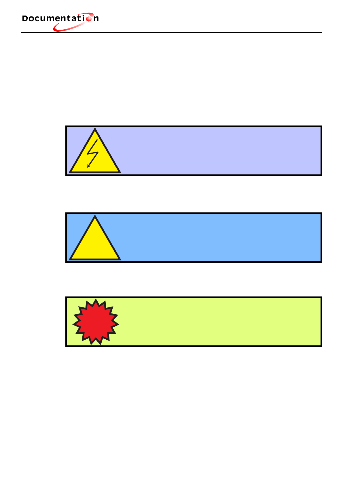
The following safety warnings are given in this manual:
How to use this manual
Electrical Hazard: Identifies possible electrical risks
which could permanently damage the appliance.
Warning: Identifes information or circumstances which
may cause personal injury or death.
!
Important: Identifies vital information for understan-
ding the product.
I
© Copyright by Fagor Electrodomésticos S. Coop. 2002. All rights reserved. The total
or partial reproduction of this document, using any type of procedure or on any type
of support, is prohibited without previous written authorisation by the owner of the trading rights. Persons failing to comply with this reservation will be pursued under the
applicable legislation and may be prosecuted.
FAGOR ELECTRODOMÉSTICOS reserves the right to introduce any modifi cations
to the characteristics of its products, without prior notice.
Page 3

technical
1.- Warnings and precautions...................................1
2.- Features.................................................................2
3.- Description of functioning ...................................3
Contents
3.1.- General description.............................................................3
3.2.- Assembly and disassembly instructions............................ 10
3.3.- Maintenance...................................................................... 25
3.4.- Diagrams........................................................................... 27
Page 4

technical
1.- Warnings and precautions
1. This manual must NOT be considered an overall guide to the repair / maintenance
of the appliance.
2. It must only be used by duly qualifi ed persons with technical knowledge applicable
to this product and with suitable testing equipment and tools.
3. Before any electrical appliances are repaired they must be disconnected (unplugged) from the mains.
4. Before servicing the appliance, its earth connection and insulation resistance must
be checked.
5. Safety precautions must be taken for protection against accidents caused by sharp
metal or plastic edges.
Warnings and precautions
6. After servicing, the electrical safety of the appliance must be checked again. In the
case of appliances connected to a water intake (i.e. washing machines, dishwashers,
cooking centres), check for any leaks in the pipes and valves and rectify where necessary.
7. Attempting to carry out DIY maintenance and repair work on complex equipment
can be dangerous. The company recommends consulting your Service Centre in
case of any problems with these appliances.
8. Although the company has made every effort to guarantee the accuracy of the information given in this guide, they have no liability for any inconveniences or losses
arising from errors in the same.
1
Page 5

technical
2.- Features
Removable detergent drawer
Drum open button
Lever for placing on wheels
Drain pump access hatch
Cover positioner
Short wash
Hand wash
Extra rinse
Features
Anti-crease stop
Adjustable 100-1100 r.p.m. drain
2
Page 6

technical
3.- Description of functioning
3.1.- General description
Dimensions
Height: 85 cm
Length: 60 cm
Width: 40 cm
Weight: 57 Kg
Draining
Maximum height: 90 cm
Description of functioning
Minimum height: 65 cm
Length of drain hose: 1.40 maximum 2.50 m
Capacity 5Kg
Electrical Characteristics
230V
50H
10 Amp
2250W
Water Consumption according to model
59 litres
64 litres
74 litres
Temperature control
By adjustable cold thermostat to 90º
By potentiometer (10 Kohms)
By temperature thermostat to 74º which detects temperature via tub wall
A 10K potentiometer allows the temperature selection from cold to 90º by means of
the module reading the information transmitted by the sensor (NTC)
3
Page 7
technical
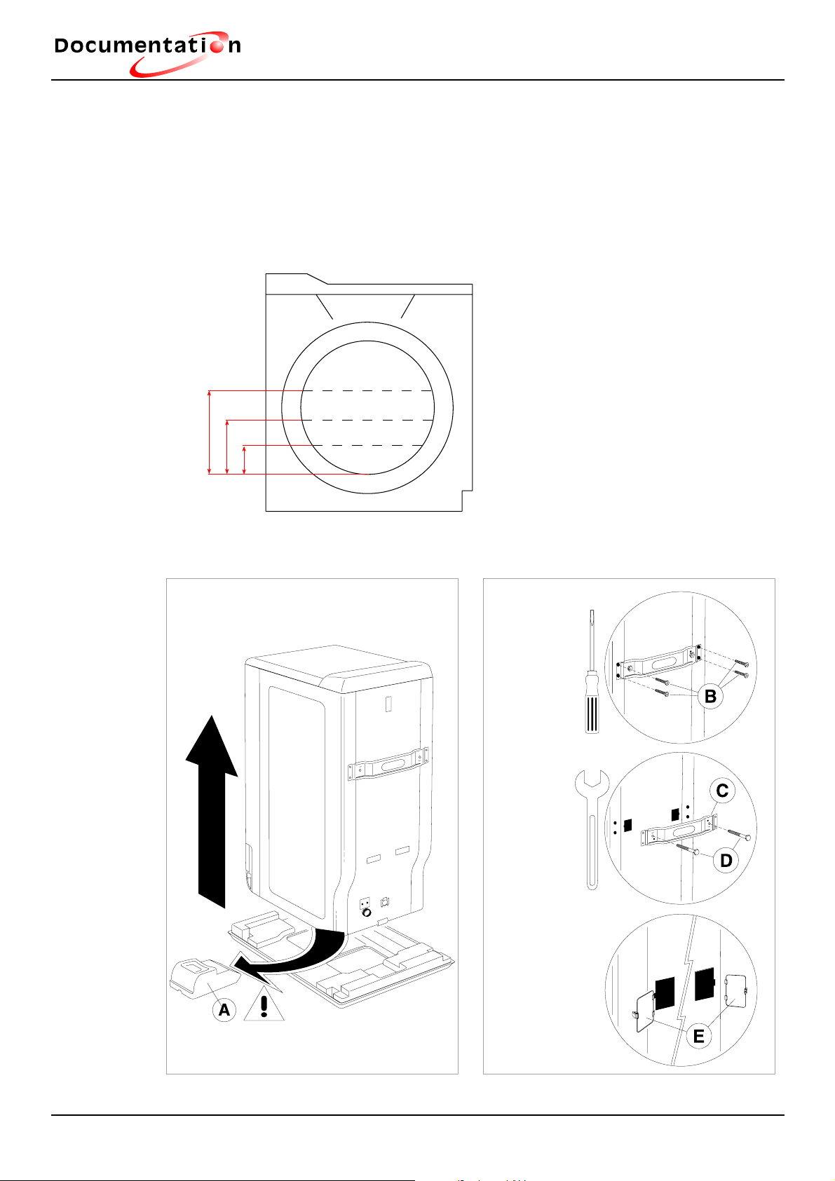
Water levels
Average wash level 72 mm (A) (11-12 Pressure switch)
Average rinse level 167 mm (B) (11-14 Pressure switch)
Average overfl ow level 287 mm (C) (11-16 Pressure switch)
Description of functioning
C
B
A
Packaging and blocking
Dibujo 1 ibujo 2.1
Dibujo 2.2
Dibujo 2.3
2
2
4
Page 8
technical
Reference plate
Description of functioning
FAGOR
MOD: 1FT-116D-DE
Nr: 02 11 00530
COD: 925010293
IPX4
Type: MAP3BNP315112
230 V - 50 Hz - 2250 W
10 Amp
Maximum clothes load 5 Kg
Revolutions: 110 r.p.m.
Inlet water pressure 0.7-10 bar
Model
Nº of washing machines
manufactured
Month of manufacture
Year of manufacture
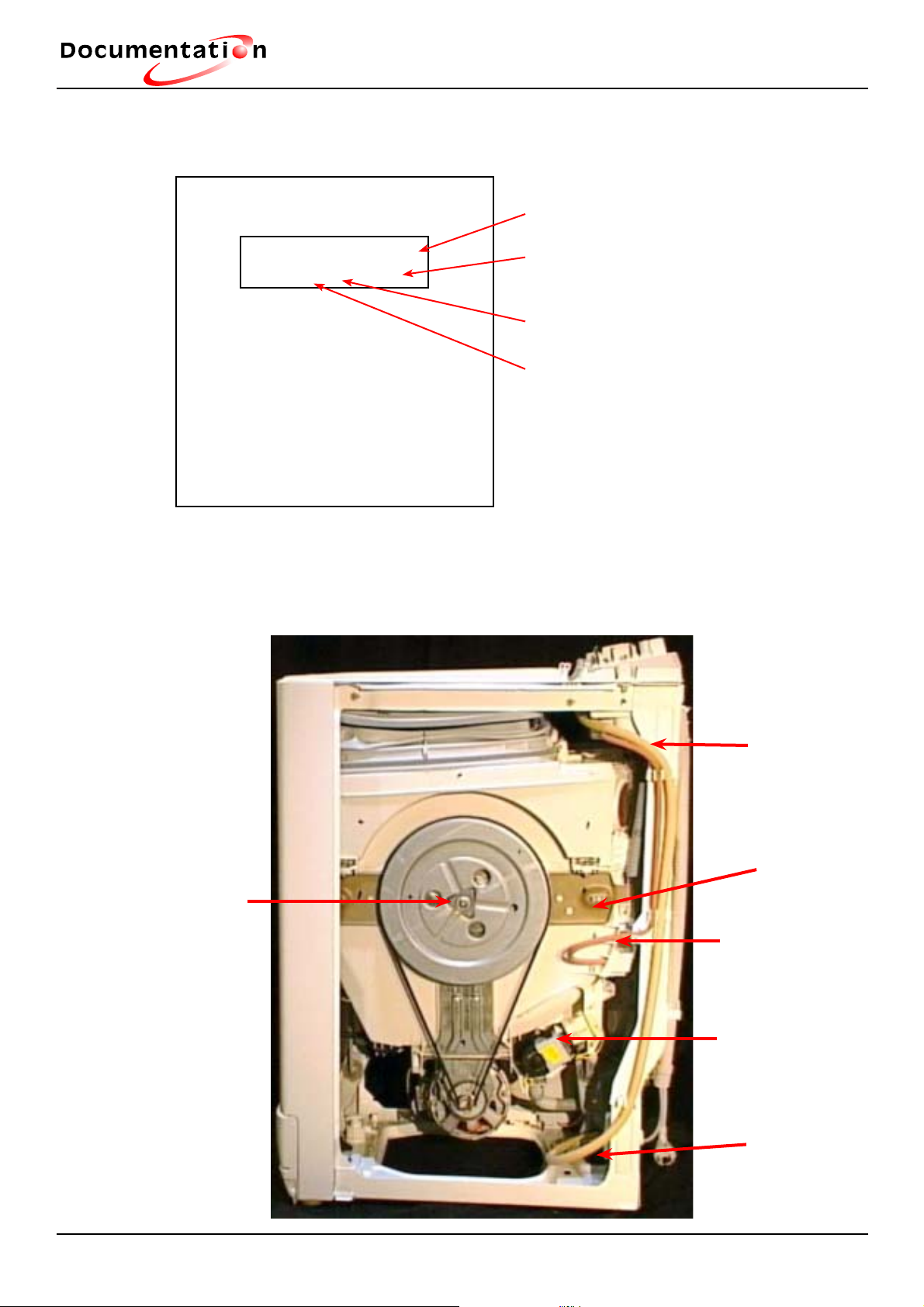
NOTE: The reference plate is located on the rear of the washing machine. There is
another label indicating the model and and date of manufacture which can be viewed
by removing the detergent drawer.
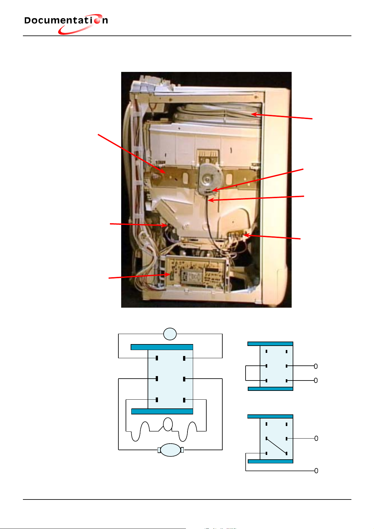
Right side view
Pulley
fixing
screw
(Torx 40)
Water supply
tube
Bearing holder
support
Pressure switch
tube
Drain pump
Electrovalve
position
5
Page 9
technical
TG
Brown
Brown
Black
Blue
Red
White
1
4
5
6
3
2
T
Rotor
1
4
5
63
2
1
4
5
63
2
230 V
230 V
Anti-clockwise
connection
Clockwise
connection
Left side view
Description of functioning
Bearing holder
support
Thermostat
Electronic
Module
Muffle
Drum position
sensor
Position sensor
wiring
Washing ele-
ment + NTC
1150 r.p.m. universal type motor connection
E1 (Stator): 1.67 ohms Rotor: 70 ohms
E2 (Stator): 0.84 ohms TG (Tacho-generator): 1.6 ohms
T: Motor heating thermostat
6
Page 10
technical
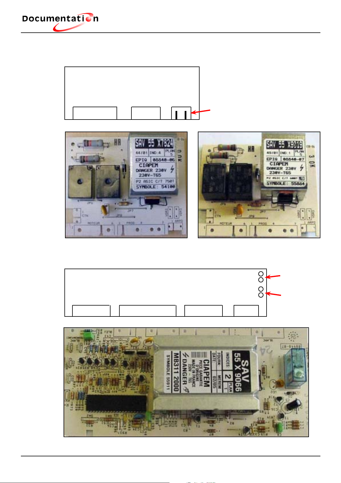
Modules
P2A Type
Electronic Module
Motor
Connection
1-2-3-4-5-6 1-2-3-4
Description of functioning
Drum Position Sensor Connection
(according to model)
P3B Type Module
P3B Type
Electronic Module
White Connctor. White Connctor. Black Connctor. Blue Conntr.
1-2-3-4-5-6 1-2-3-4-5-6-7-8-9 1-2-3-4-5-6 1-2-3-4
1- Positioner
Connection
2- NTC
Connection
7
Page 11
technical
Description of functioning
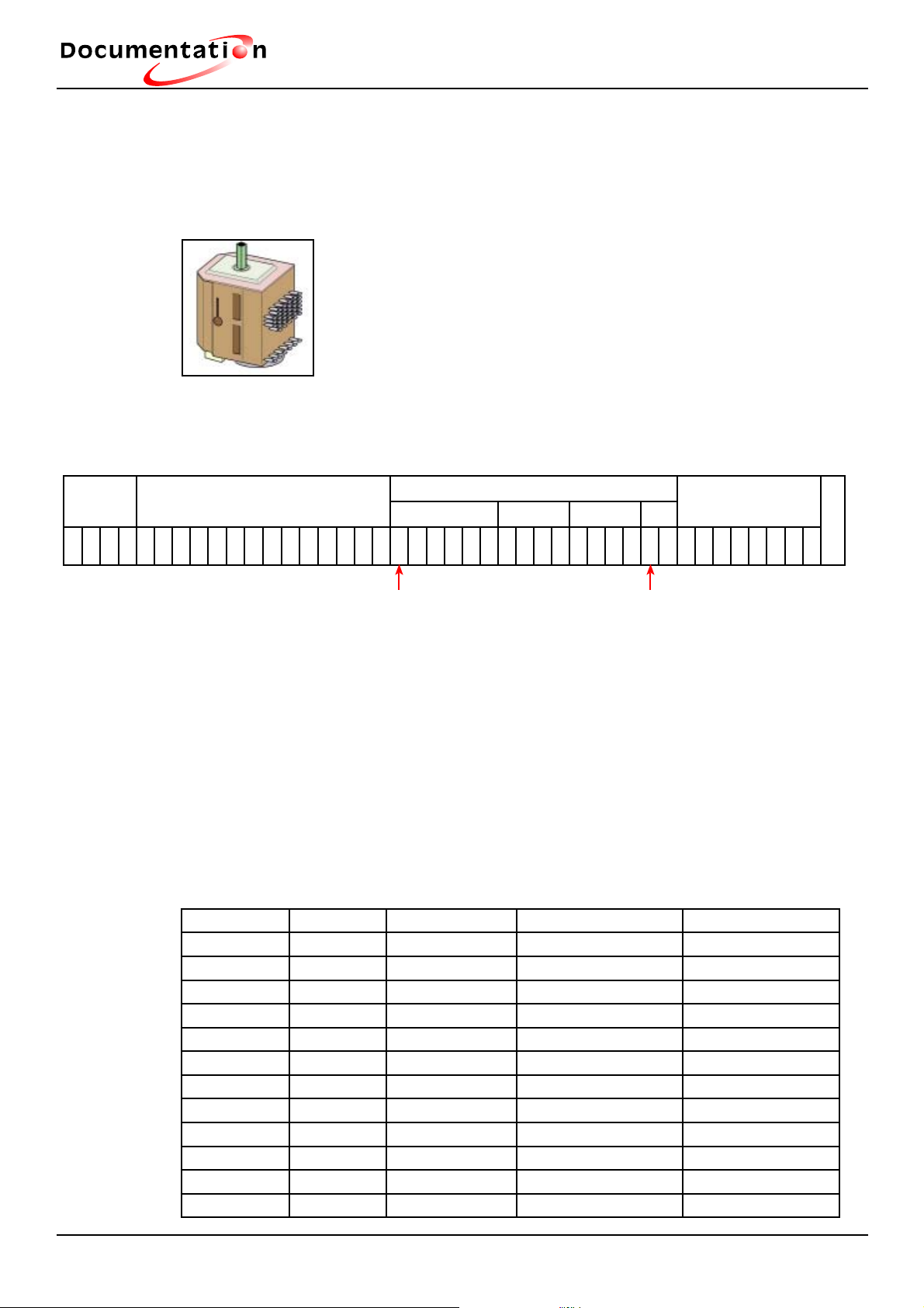
Electro-mechanical Programmer
A micro-motor displaces the cams, allowing the contacts supplying the different elements to open or close.
Electrovalve
Element
Drain pump
Door lock
Supplies and controls motor reversal (low spin speed washing
machines)
Wash Programme and duration times for a 500 r.p.m. model.
Prewash Wash
1234567891 01 11 21 31 41 51 61 71 81 92 02 12 22 32 42 52 62 72 82 93 03 13 23 33 43 53 63 73 83 94 04 14
R1 R2 R3 R4
Rinses
Spin dry
Bleach Fabric Softener
Prewash 12´- 1.5´- 7.5” - 82.5”
Wash: 3´- 12´- 6´- 6´- 6´- 12´- 3´- 3´- 6´- 12´- 12´- 1.5´- 7.5” - 82.5”
Rinse R1 6´- 1.5´- 7.5” - 37.5” - 7.5” - 37.5”
Rinse R2 6´- 1.5´- 7.5” - 82.5”
Rinse R3 6´- 1.5´- 7.5” - 82.5”
Rinse R4 6´- 7.5”
Spin 7.5”/90” - 7.5” - 37.5” - 7.5” - 37.5” - 12´- 1.5´
Programming types
Model R.P.M. Card type Programming type Reference
1FT-116 1100 MB-311 P3B LB55X9066
1FT-96 900 MB-313 P3B LB55X9067
1FT-76 700 ASIC P2A LB55X9020
1FT-53 500 NO P1B 1FT-51 500 NO P1B 1LT-86 400-800 ASIC P2A LB55X9020
1LT-63 600 ASIC P2A LB55X9019
1LT-53 500 NO CARD P1B 1LT-51 500 NO CARD P1B LA-363 600 ASIC P2 LB55X9019
LA-343 400 NO CARD P1A LA-143 400 NO CARD P1A -
S
T
O
P
2
8
Page 12

technical
Description of functioning
P1A P1B
Constant speed at 400 r.p.m. Constant speed at 500 r.p.m.
Heating chronometric or by thermostat
1/2 Load 1/2 Load
Anti-crease Anti-crease
Eco on chronometric heating Eco on chronometric heating
1 wash cycle 2 wash cycles
Spin dry Spin dry
Consumption 84 litres Consumption 74 litres
P2A
Variable speed at 750 r.p.m.
Heating chronometric or by thermostat
1/2 Load
Anti-crease
Eco on chronometric heating
2 wash cycles
Spin dry
Consumption 74 litres
9
Page 13

technical
3.2.- Assembly and disassembly instructions
Removing the side panels
Tools required:
- Nº 7 hex key
Removal procedure
- Place the appliance on the wheels
- Remove the screws in the rear of the appliance (3 per panel)
- Carefully lift off the left or right panel by sliding it completely towards the rear.
To replace the panels:
Description of functioning
- Place the bottom of the panel on the support tabs and fold it towards the appliance.
- Push it towards the front and replace the fi xing screws.
Removing the control panel
Tools required:
- Medium-sized screwdriver for countersunk screws.
Removal procedure:
- Turn the programming dial and selectors to downwards position.
- Remove the rear fi xing screw ().
- Unclip the control panel cover, separating it from the rear part and tilting it
forwards.
To replace it:
- Place the largest fl at surface facing downwards
- Line up the selector indicator in downwards position.
- Place the front part fi rst and then fi x the decorative part in place.
- Check the various selectors are turning properly.
Removing the Control Panel Support
Tools required:
- Thin fl at screwdriver; Nº 7 hex key; Nº 20 torx screwdriver.
10
Page 14

technical
Removal procedure:
- Remove the control panel
- Remove the buttons
- Remove the screws (A,B,C)
- Unclip the component support and tilt it towards the rear.
- Remove all the parts in order to release the component support.
To put it back in place:
- Ensure the component support screws are not blocked preventing the side panels
from being adjusted.
Description of functioning
A B
C
Removing the door
Tools required:
- Thin fl at screwdriver
Removal procedure:
- Open the door
- Remove the hinge pins (make sure you do not scratch the top with the screwdriver
shaft)
- Pull upwards to remove the door.
To replace it again:
- Repeat the above steps in reverse order.
Pins
11
Page 15

technical
Removing the Single / Dual Pressure switch
Tools required:
- Thin fl at screwdriver, screwdriver for countersunk screws, Nº 7 hex key, Nº 20 torx
screwdriver
Removal procedure:
- Remove the control panel
- Remove the component support
- Remove the right side panel
- Remove the pressure switch connection hose. For ease of removal, carefully push
the tub unit towards the front part.
Description of functioning
- To remove the pressure switch, free it from its housing located under the component
support with the aid of a small fl at screwdriver.
- Carry out the above operation in reverse order.
To replace it again:
Carry out the above operation in reverse order.
Removing the Compression Chamber
Tools required:
- Nº 7 nut wrench, fl at screwdriver, tool for fastening
door leaves
Removal procedure:
- Remove the right side panel.
- Disconnect the compression chamber tube
- Fasten the two leaves of the drum door with the aid of the tool.
- Remove the moving omega.
- Remove the drain fi lter.
- Reach inside the opening on the left next to the moving omega and
release the compression chamber, pressing on the grooved part while using a fl at
screwdriver for leverage.
To replace it again:
- Carry out the above operation in reverse order.
12
Page 16

technical
Removing the sleeve cover
Tools required:
- Nº 20 torx screwdriver
Removal procedure:
- Remove the 5 screws located under the edge of the sleeve.
- To remove the sleeve cover, carefully detach it from the top
of the sleeve.
To replace it again:
- Carry out the above operation in reverse order.
Description of functioning
Very important: for safety reasons, the screws must be put back in the same fi xing
holes.
Removing the muffl e / load door rubber
Tools required:
- Nº 20 torx screwdriver, Nº 6 tightening wrench
Removal procedure:
- Remove the side panels.
- Remove the sleeve cover
- Remove the collar of the spring holding the seal around
the distributor in place.
- Unscrew the sleeve fi xing collar from the upper half of the
tub (A).
- Remove the sleeve
To replace it again:
- Carry out the above operation in reverse order.
Removing the tub lining cover
Tools required:
- Nº 7 hex key, fl at screwdriver, Nº 20 torx screwdri-
ver
Removal procedure:
- Remove the side panels.
- Remove the control panel
13
Page 17

technical
- Remove the control cable from the cam pin.
- Remove the door.
- Release the pressure switch.
- Tilt the component support towards the rear.
- Remove the sleeve cover.
- Remove the sleeve from around the distributor.
- Remove the distributor fi xing screw.
- Remove the fi xing screws from the upper part.
- Remove the door safety device.
- Remove the upper part.
Description of functioning
To replace it again:
- Carry out the above operation in reverse order.
Important: For ease of handling, fi rst place the sleeve around the distributor. Do not
block the fi xing screws of the sleeve cover. Remember to pass the cable through the
component support.
Removing the distributor
Tools required:
- Nº 20 torx screwdriver, medium fl at screwdriver
Removal procedure:
- Remove the control panel
- Remove the left side panel
- Remove the detergent drawer and support.
- Release the distributor control cable.
- Tilt the component support.
- Remove the sleeve cover.
- To remove the upper part of the distributor sleeve:
- Remove the spring.
- Remove the 2 distributor fi xing screws.
- To release the distributor, free it by pulling it out towards the front and lifting it up.
- To release the distributor, cut the fi xing collar of the water intake.
14
Page 18

technical
To replace it again:
- Carry out the above operation in reverse order.
Important: The collar must be replaced by another one of identical characteristics.
Adjusting the Distributor
Thread the cable under the cam and then insert the end in the distributor housing.
Place the distributor pin in the widest part of the cam (corresponding to prewash)
Description of functioning
Cam Distributor
Stop position of sheath
1- Prewash position
2- Wash position
3- Fabric softener position
15
4- Bleach position
Page 19

technical
Door lock and Omega
Tools required:
- Nº 20 torx screwdriver
Removal procedure:
- To release the door locking device, press bracket and slide unit out to the right.
- Remove the sleeve cover.
- Remove the upper part of the sleeve.
- Remove the cabling in order to release the door lock.
To replace it again:
- Carry out the above operation in reverse order.
Description of functioning
4.4 Kohms
Omega
Depending on the model, the omega may be fi xed to the drum in one of two ways,
with a screw or with a swing-out device
Screw
fixing
Press swing-out device to move omega
16
Page 20

technical
Removing the drain pump
Tools required:
- Nº 7 hex key, Nº 20 torx screwdriver
Removal procedure
- Drain the remaining water out through the drain arch (use a bowl).
- Tilt the machine to the left (remember to protect it).
- Remove the right side panel.
- Disconnect the cabling.
- To remove the drain pump, remove the three fi xing screws.
To replace it again:
Description of functioning
- Carry out the above operation in reverse order.
- Connect the cabling again before re-adjusting the pump.
155 Ohms
30 W
16 Litres
Synchronous
Removing the belt or pulley
Tools required:
- Nº 7 hex key, Nº 40 torx screwdriver for countersunk screws
Removal procedure:
- Remove the right side panel
- If necessary, remove:
- the belt, releasing it from the drum control pulley,
- the pulley, removing screw A
To replace again:
- Carry out the above operation in reverse
order.
Important: Clean the threaded hole and remove all thread brake remains. The fi xing
screw must always be replaced when the pulley is removed.
17
Page 21

technical
Removing the element with or without thermistor (depending on model)
Tools required:
- Nº 7 and 10 nut wrench
- Tool for holding drum door leaves in place.
Removal procedure:
- Remove the left side panel
Either:
- Disconnect element cabling
- Remove element fi xing nut
- Remove immersion heater.
Description of functioning
or:
- Disconnect connection cables leading from thermistor to power card
-Remove element fi xing nut
- To remove the thermistor, pull it carefully forwards.
To replace it again:
- Carry out the above operation in reverse order.
Important: - The earth connection tab must be facing upwards.
- It must be ensured that the element is correctly inserted in the bracket
located inside the tub. To do this, remove the moving omega and then immobilise the
drum door leaves.
- Check the correct position of the element in the bracket located in the
lower part of the tub. If the bracket is loose, there is a hole for fi xing it with a 3.5 x 12
stainless steel screw.
- The cabling route must be correctly followed.
2000 W - 25 Ohms
Internal thermofuse
NTC
12 Kohms at 20ºC
18
Page 22

technical
Removing the Motor
Tools required:
- Nº 7 nut wrench, Nº 20 bent torx wrench, fl at screwdriver
Removal procedure:
- Remove side panels.
- Remove belt.
- Disconnect motor cabling.
- Remove the motor, releasing the two fl anges with a fl at screwdriver.
To replace again:
- Carry out the above operation in reverse order.
Description of functioning
Adjusting pulley alignment:
- Loosen the four motor support screws.
- Adjust the alignment so that the belt has a play of 1 - 2 mm.
- Tighten the four screws.
Removing the Electrovalve
Tools required:
- Nº 7 hex key, fl at screwdriver
Removal procedure:
- Remove the right side panel.
- Unscrew the water inlet hose located at the electrovalve inlet. Ensure the water inlet
valve is closed.
- Unclip and remove the cover.
- Remove the plastic guard from the electrovalve.
- Disconnect the electrovalve cabling.
- Pull the solenoid valve upwards to release it.
- Cut the collar to remove the solenoid valve.
To replace it:
Carry out the above operation in reverse order.
19
Page 23

technical
Removing the Upper Tub
Tools required:
- Nº 7 nut wrench, Nº 20 torx screwdriver, wide fl at screwdriver, heat-resistant putty,
after sales service reference: 55X2935
Removal procedure:
- Remove decorative cover.
- Remove sleeve cover
- Release sleeve from upper half of tub.
- Remove screws from cross-piece.
- Tilt the upper part with the component support and sleeve.
Description of functioning
- Remove the belt and control pulley from the drum.
- Remove the reed switch sensor (depending on model).
- Remove the screws located on each side of the tub half.
- Separate the two tub halves, making leverage on the four fi xing points.
Note: It may appear diffi cult to separate the two halves of the tub due to the sealing
cord sticking.
Washing machines of over 1000 r.p.m have a 20Kg injected tub and those of under
1000 r.p.m. a 16Kg injected tub.
Making leverage
- Lift off the upper half of the tub.
To replace it again:
- Carry out the above operation in reverse order.
Very important: To ensure water-tightness:
- The bottom half of the tub must be cleaned.
- A sealing cord must be evenly applied in the groove of the lower half of the tub.
20
Page 24

technical
Removing the Drum
Tools required:
- Nº 7 hex key
- Wide fl at screwdriver
- Nº 20 torx screwdriver
- Nº 40 torx screwdriver
- Screwdriver for countersunk screws
- If possible, a nº 6 ratchet wrench
Removal procedure:
- Remove decorative cover
Description of functioning
- Remove sleeve cover
- Tilt the upper part with the component support.
- Remove the sleeve from the upper part of the tub
- Remove the belt and control pulley from the drum.
- Remove the reed switch sensor (depending on the model).
- Remove the upper half of the drum.
- Remove the two bearing support cross-pieces.
- Remove the drum, separating the lower half of the tub in the drum axis holes.
To replace it again:
- Carry out the above operation in reverse order.
- Before putting the drum in place, the right and left drum lids must be bent inwards.
Important: to ensure water-tightness, the two tub halves must be cleaned before
applying a new sealing cord.
Capacity 42 litres
Right lid position
21
Page 25

technical
Removing the lower tub
Tools required:
- Nº 7 hex key
- Wide fl at screwdriver
- Nº 20 torx screwdriver
- Nº 40 torx screwdriver
- Screwdriver for countersunk screws
- If possible, a nº 6 ratchet wrench
Removal procedure:
- Remove control panel.
Description of functioning
- Remove sleeve cover.
- Tilt the upper part with the component support.
- Remove the sleeve from the upper part of the tub
- Remove the belt and control pulley from the drum.
- Remove the reed switch sensor (depending on model).
- Remove the upper half of the drum.
- Remove the two bearing support cross-pieces.
- Remove the drum.
- Disconnect the motor cabling and the drain pump.
- Remove the thermostat bulb.
- Remove the unit consisting of the lower half of the tub, the motor and the drain pump
by lifting it up and releasing the springs.
- Remove all the parts.
To replace it again:
- Carry out the above operation in reverse order.
Important: to ensure water-tightness, the two tub halves must fi rst be cleaned.
22
Page 26

technical
Removing the bearing from the pulley side
REMOVE THE BEARINGS SEPARATELY
Tools required:
- nº 7 hex key
- Nº 20 torx screwdriver for countersunk screws
- Nº 40 bent wrench for countersunk screws
- Torch
Removal procedure
Description of functioning
- Remove the right side panel.
- Remove the belt and control pulley.
- To remove the reinforcement plate, loosen the 3 screws around the drum shaft
- Remove the fi xing screws from the cross-piece.
- Remove the interface and then the V ring restrictor
- Remove the cross-piece and the roller bearing
To replace them again:
- Carry out the above operation in reverse order.
- Important: the pulley fi xing screw must be changed.
- Clean the drum shaft before applying the detergent.
- Clean the V ring restrictor, being careful not to damage the edges.
- Check with the torch.
- Place the reinforcement plate, with the lower part fi rst.
Bearing holder support
Motor support
- Tighten the screws in the order shown.
Screw tightening order:
- 4 screws around the shaft (cross-tighten them).
- 2 screws on the ends of the cross piece.
- 2 fi xing screws for tub halves.
Important: Do not forget the washers. Screw them back in using the holes which
have not yet been used.
23
Page 27

technical
Removing bearing from side opposite pulley
REMOVE THE BEARINGS SEPARATELY
Tools required:
- nº 7 nut wrench
- Nº 20 torx screwdriver for countersunk screws
- Nº 40 bent wrench for countersunk screws
- Torch
Removal procedure:
- Remove the left side panel.
- Remove the bearing support fi xing screws.
Description of functioning
- Remove the interface and then the V ring restrictor
- Remove the bearing support and the ball bearing
To replace it again: Bearing holder support
- Carry out the above operation in reverse order.
- Clean the drum shaft.
- Cover the V ring restrictor, taking care not to damage the edges. Check with the
torch.
- Tighten the screws in the order shown.
Order for tightening screws:
- Central nº 40 torx screw
- 4 screws around shaft (cross-tighten them).
- 2 screws on the ends of the bearing support
- 2 fi xing screws for tub halves.
Important: Do not forget the washers. Screw them back in using the holes which
have not yet been used.
24
Page 28

technical
2
Dibujo 13
1
3.3.- Maintenance
Cleaning the pump fi lter
This fi lter traps any small objects which may have been left in the clothes and pre-
vents pump malfunctioning as a result.
The fi lter is cleaned as follows:
- Open the fl ap doors to the drum. At the bottom of the drum you will see a plastic part,
“A” (Picture 12)
Description of functioning
Dibujo 12
A
- Unblock this plastic part. (Picture 13).
To do this: -Insert a rod-shaped object (a pencil or bolt, for example) in the hole in the
top of part “A”.
- Press this rod down vertically, pushing part “A” towards the right at the
same time until it comes out of its housing.
- Remove part “A”.
- Turn the drum slightly with the fl ap doors open towards the front of the machine
(Picture 14).
When part “A” is removed the openings are freed allowing access to the pump fi lter
“B”.
- Remove the fi lter (Picture 14)
Dibujo 14
B
25
Page 29

technical
CLANG
2
1
Dibujo 16
- Remove the objects trapped inside it.
- Rinse it under the tap (Picture 15).
- Ensure the fi lter housing is clean and then replace the fi lter, pressing it into the
housing.
Description of functioning
Dibujo 15
- Put part “A” back in place, ensuring it is correctly positioned in the openings at the
bottom of the drum, and pressing it towards the left until it is perfectly fi tted in place
(Picture 16).
26
Page 30

technical
C4
22
B3
G5
G4
B
23
A
B
4
A
3
A
450
A
F2
A3
V
B
A
B
F
F3
B4
B
B2
C3
B
A
A2
B
A
2
A
B5
C5
AP
A5
A4
4
5
GV
C
C2
2
PV
3
E2
12
D4
D5
D3
BA
7
1
N
14
13/
P
F4
F5
THERMOSTAT
DOOR BLOCK
MAINS BLOCK
START/STOP
DOOR LOCK
CONTACT
SWITCH
SAFETY
ELEMENT
COLD
PROGRAMMER
ELECTROVALVE
DRAIN PUMP
1/2 LOAD
PRESSURE SWITCH
MOTOR
3.4.- Diagrams
500 r.p.m
Description of functioning
27
Page 31

technical
Description of functioning
Mod. 1LT-51 Y 1LT-53
TPO
S
SPIN
R3
R2
R1
WASH
STO
SPIN
R4
R3
R2
RINSES
R1
WASH
PL
P
Level
PAC
2
1/
CH
ACP
cl
Drain
PREWASH
WASH
RUNNING
BLEACH
CAM
DISTRIBUTION
MMES
PROG
S
PART
DE
SEC
ENJ.
Fr
40
SEC
ENJ.
Fr
Fr
30
4060
0
PL
NORO
MO
ER
THRACH
MM
RA ES
OG
PR
STOP
0
6
3'
9
82,5"
8
7,5"
7
75"/90"
6
ACP7,5"
5
7,5"
4
6'
3
3'
2
N+3'
1
3'
5
0
N+3'
9
82,5"
8
7,5"
7
1,5'
6
N+3'
5
N+12'
4
STOP
3
1,5'
2
Va40co
30
40
E69060
12'
1
37,5"
4
0
7,5"
9
37,5"
8
7,5"
7
75"/90"
6
ACP7,5"
5
7,5"
4
6'
3
82,5"
2
7,5"
1
1,5'
3
0
6'
9
82,5"
8
7,5"
7
1,5'
6
6'
5
37,5"
4
7,5"
3
37,5"
2
7,5"
1
1,5'
2
0
6'
9
82,5"
8
7,5"
7
1,5'
6
N+12'
5
N+12'
4
N+6'
3
N+3'
2
N+3'
1
N+12'
0
1
N+6'
9
N+6'
8
N+6'
7
N+12'
6
N+3'
5
82,5"
4
7,5"
3
1,5'
2
N+12'
1
DURATION
INT/250 V.
MOTIVE CONT.
FIXED CONT.
CAM Nº
ELEMENT
MICROMOTOR DETECT
D4
D5
CONDENSER PV
C2
DRYING
RHYTHM+/-
D3
A
BBABABA
8
7
C3
6
CONDENSER GV
C1
1/2 LOAD
NORMAL RHYTHM
B1
B2
B3
4
PUMP
E.V.
B4
B5
A
B
3
GENERAL
A2
ABA
2
CONDENSER PV
A4
0
6
9
8
7
6
5
4
3
2
1
5
00
9
8
7
6
5
4
3
2
1
4
0
9
8
7
6
5
4
3
2
1
3
0
9
8
7
6
5
4
3
2
1
2
9
8
7
6
5
4
3
2
1
0
1
9
8
7
6
5
4
3
2
1
7,5"
45"3'1.5'6'12'
P
SLOW RHYTHM
CONDENSER GV
TC
TB/2
TB/24TBTBx4
A5
B
1
TBx8
AC
G4
A
G3
G5
B
23
2"6" 7" 6" 3"
2"3" 3"
3"6" 6" 6" 6" 6"
3"3" 6" 34"
6" 18"
4"3"
0, 14,
3" 5" 8" 5" 6" 6"
+
PV
F1
F2
F3
A
BPV
22
28
Page 32

technical
700 r.p.m.
SELECTOR 230V
Description of functioning
START/STOP
SWITCH
SUPPRESSION
FILTER
2B
2
2A
ANTI-CREASE
ADJUSTABLE
THERMOSTAT
1B
1A
1
ELECTROVALVE
2A
PUMP
HEATING ELEMENT
4
4B
PROGRAMMER
DOOR LOCK
4A
DOOR LOCK
CONTACT
5
5A
RINSE +
PRESSURE SWITCH N1
13/14
1
12
P
6B
F2
F3
F
55
5
54
47K
6A
12
13
S
1
4
12345
T
R
3
5
2
61234
T
S
S
R
CARD
R
PH
CAD
ESSO
RC
POTENTIOMETER
DRAIN
100K
WOOL
5B
53
52
29
Page 33

technical
Description of functioning
ONTI
POSI
S.PO
0
56
55 050454
03
53
02520151
ML 52149L
S
TE
3
3
3
3
3
3
3
3
3
6/3
3
3
3
3
3
3
6/3
3
6/3
6
3
3
3
3
6
3
3
6/3
3
6
6
6
6
6/3
3
3
3
3
6/3
6
6/3
3
3
6
6
6
6
6/3
3
3
6/3
STOP
7.5"
STOP
PCL/3
7.5"
2'52.5"
2'52.5"
PCL/7.5"
2'52.5"
MINU
OP
C
OP
C
R5
R1
ST
DRAIN
ES
R4
R3
R2
R1
PREWASH
ST
DRAIN
ES
R4
R3
R2
BLEACH
0L9
PREWASH
**
****
SOFTENER
**
**
** *
**
3
2
1
)(T
4BLEACH
5
HEATING
STOP WITH LOAD
1B
1A
1
B
A
1C
T.P.
C.
2A
A
LIGHT
2B
1
VE
AL
TROVEC
EL
DRAIN
4B
4A
4
B
A2CB
4
30
PUMP
1/2 LOAD
6B
6A
5
A
SLOW CAD.
8A
6
A5B
6
NORMAL CAD.
8B
B
WASH
PREWASH
PROGRAM SELECTOR
SOFTENER
Page 34

technical
1100 r.p.m.
Description of functioning
E3
F3
TEMP. POWER
4
3
2
42
THERMOSTAT
A
B
F2
10
B
F
G5
G3
G4
1
2
E4
E5
E
23/
22
P
SENSOR
SELECTOR 230V BLOCK
SUPPRESSION
FILTER
G
24
N2
SPEED POWER
HEATING ELEMENT
ELECTROVALVE
EV
PRESSURE SWITCH
START/STOP
SWITCH
PROGRAMMER
DOOR LOCK
13/
12
PUMP
14
P
DOOR LOCK
CONTACT
1
N
A3
A
C
A4
D
C3
C2
D2
DRUM POSIT.
RINSE
5
4
62
3
2
D5
D4
B2
B
7
A
B
5
8
7
5
CARD
4
3
9
2
R
5
S
4
R
6
3
S
2
T
T
F5
3
2
R
5
S
4
Ta ch
y
WOOL
SHORT
C4
A
B
A
B5
3
B
2
B
B4
D3
31
Page 35

technical
Description of functioning
0
6
9
8
7
6
5
4
3
2
1
0
5
9
8
7
6
5
4
3
2
1
0
4
9
8
7
6
5
4
3
2
1
POSITION
0
3
9
8
7
6
5
4
3
2
1
2
0
9
8
7
6
5
4
3
2
1
0
1
9
8
7
6
5
4
3
2
1
s
15
mn
1
TIME
A4
A3A1A3
16
(A)
OR
CTSE
B
A
1C
001
(0. A)
C
DECO
BAA
B5C4*
*
A)
001
(0.
E
CODE
B
3C 2C
C3
A)
001
001
(0. A)
(0.
A
B
CODEBCODE
A
5C
D4
A)
001
(0.
CODE B
A
D3
7C
E4D5E5
E3
A)
A)
.1
(0
001
(0.
D
LOCK LIGHT
CODEBCTP
A
B
9C
.1
A)
(0
E1
E3
A)
510.
(
HEATING
B
A
10C
OPST
R3
R2
R+
R1
OPR3ST
R2
R+
R1
OP
ST
DRAIN DRAIN DRAIN
R3
R2
R+
R1
WASH WASH WASH
PREWAS PREWAS
PROGRAMME SELECTOR
** ** ** ** * **
1
(T)
PREWASH
3
2
4
WASH
BLEACH
SOFTENER
5
32
Page 36

© FAGOR ELECTRODOMESTICOS, S.COOP. 2003
Bº San Andrés, s/n
20500 Mondragón (Gipuzkoa)
España (Spain)
 Loading...