

Page 1
Fagor Automation S. Coop.
Manual code: 14460054
Manual version: 0612
Software version: 4.xx
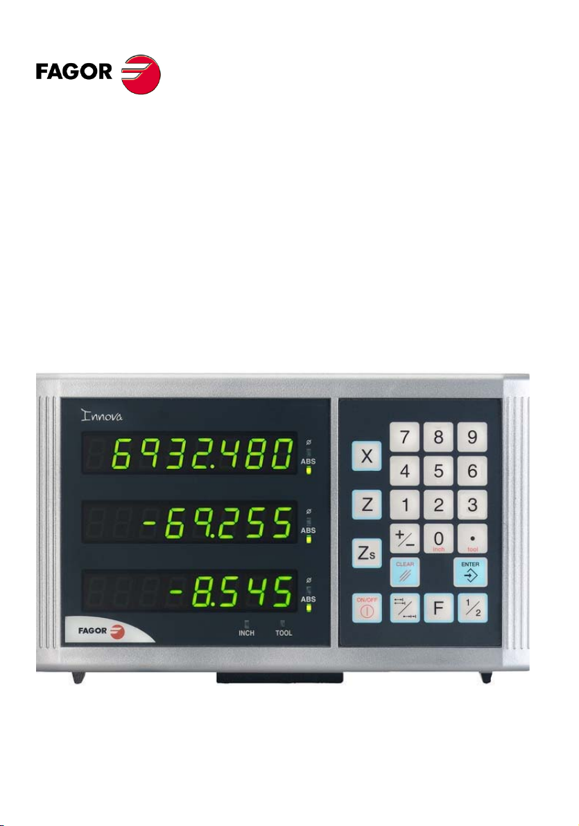
20i-T / 30i-T
20i-T B / 30i-T B
Installation/Operation Manual
Page 2

INDEX
1 DRO description ..........................................................................................3
1.1 Front panel ........................................................................................................................ 3
1.2 Turning the unit on and off .............................................................................................. 4
2 DRO operation .............................................................................................5
2.1 Display modes .................................................................................................................. 5
2.2 Incremental, absolute and with respect to Machine Reference Zero .......................... 6
2.2.1 Example .............................................................................................................................. 7
2.3 Machine Reference selection and search ...................................................................... 9
2.3.1 Home search sequence ......................................................................................................9
2.4 Operation with tools ....................................................................................................... 10
2.4.1 Tool Preset ....................................................................................................................... 10
2.4.2 Deleting all tool offsets ..................................................................................................... 10
2.5 Special operations.......................................................................................................... 11
2.5.1 Scaling factor .................................................................................................................... 11
2.5.2 To access the special functions (Hold, taper calculation, calculator) ............................... 11
2.5.3 Coordinate freeze (HOLD). ............................................................................................... 11
2.5.4 Taper (cone) calculation ................................................................................................... 12
2.5.5 Calculator ......................................................................................................................... 13
2.5.5.1 Operating with the calculator. ........................................................................................... 13
2.5.5.2 Recall and Reset modes ..................................................................................................14
3 DRO installation ........................................................................................15
3.1 Installation of the built-in model ................................................................................... 15
3.2 Rear panel ....................................................................................................................... 16
3.3 General technical characteristics ................................................................................. 17
3.4 Connections .................................................................................................................... 17
3.4.1 Connection of the feedback systems ................................................................................ 17
3.5 Easy setup....................................................................................................................... 18
3.5.1 Accessing the "Easy Setup" mode ................................................................................... 18
3.5.2 Operating mode. ............................................................................................................... 18
3.5.3 Power and machine connection ....................................................................................... 19
3.6 Installation parameters .................................................................................................. 19
3.7 Parameters to configure axis position reading and display....................................... 21
4 Appendix ....................................................................................................27
4.1 UL seal............................................................................................................................. 27
4.2 CE seal............................................................................................................................. 27
4.2.1 Declaration of conformity .................................................................................................. 27
4.2.2 Safety conditions .............................................................................................................. 28
4.2.3 Warranty terms ................................................................................................................. 30
4.2.4 Material returning terms .................................................................................................... 30
4.3 Error codes ..................................................................................................................... 31
4.4 Maintenance .................................................................................................................... 32
(2/32) - Installation/Operation - 20i-T / 30i-T - V0612
Page 3
1.1 Front panel
Each axis display has eight 14.1mm high LEDs and another one for the minus
sign (-).
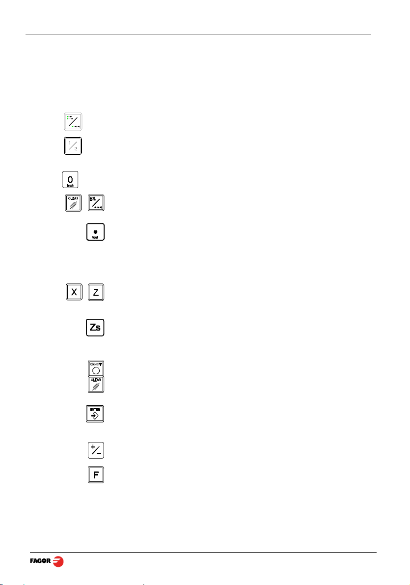
Description of LED's and keys:
ABS It stays on when operating in absolute mode and off when in incremental
mode. To access it or quit it, press this key.
Φ It stays on when operating in diameter mode. In this mode, the DRO displays
twice the actual axis movement. To access it or quit it, use this key if allowed
by installation parameter PAR04.
INCH It stays on when working in inches and off when doing it in millimeters. To
access it or quit it, press this key.
To get into and out of home search mode.
Selection of the current tool.
There are 20 tools that may be set for the part when using absolute
coordinates. The possible reference points (datum points) are from 0 to 19.
The 20i-T model shows the active reference on the display at all times,
whereas the 30i-T model only shows it when it is selected, after pressing the
reference key.
To select the axis or preset it with a certain value.
To zero the axis when the "quick zeroing" mode has been activated (see
PAR11 in the installation manual).
Only at the 30i-T. Key to select whether the 2nd display corresponds to "Z
"Z
" or to the "Z1+Z2" combination respectively. Every time this key is
2
pressed, the rightmost digit of the 3rd display rotates from "1" to "2" and off
respectively.
To turn the display off while keeping track of the axes position at all times.
To cancel or abort an operation already initiated.
1 DRO description
1
",
To validate a preset value or another operation.
Beginning of preset when the "quick zeroing" mode has been activated (see
PAR11 in the installation manual).
To change the sign of the entered value or change from fine to coarse
resolution and vice versa.
To access the special functions (Hold, taper calculation)
V0612 - 20i-T / 30i-T - Installation/Operation - DRO description - (3/32)
Page 4

1.2 Turning the unit on and off
It turns on automatically when applying voltage or after pressing the on/off
key.
It shows Fagor dro or the corresponding error code. See the error table and
PAR11 for more options.
Turns the DRO on or off.
Precautions
Before disconnecting this unit from mains, press this key so it saves the
current position.
If the unit is turned off or there is a power outage, the DRO will try to save the
current position. If it does not have enough time to safe all the data, it will
display ERROR 2 when turned back on.
(4/32) - DRO description - Installation/Operation - 20i-T / 30i-T - V0612
Page 5
2 DRO operation
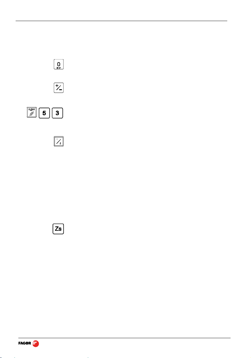
2.1 Display modes
MM / INCH conversion
To display the position of the axes either in millimeters or inches by pressing
this key depending on whether the INCH led is off or on respectively.
Fine / coarse resolution
To turn off the last decimal digit (coarse resolution) for cases in which fine
resolution is excessive, simply by pressing this key.
Number of decimals
This keystroke sequence accesses parameter PAR53. The first digit
corresponds to the number of decimals to be displayed in mm and the second
digit in inches.
Radius / Diameter
When these models are used for measuring radii or diameters, one can
display twice the real displacement of the axis (diameter) by pressing this key.
The Φled will turn on or off to indicate the double or actual reading
respectively.
Notes: - This works in this way if bit 2 of installation parameter PAR04
Z axis as a single axis or combination of both (Z1 and Z2). Only at the 30i-T:
Axis feedrate. Only at the 30i-T:
(radius/diameter) of the axis has been preset as “1” (commutated).
To display the Z axis position, one or two feedback devices may be used. One
for the cross slide (Z
When using two feedback devices, the "Z" axis display may show the position
of Z1, that of Z2 or the result from combining (adding) the positions of both
axes.
The rightmost digit of the third display shows a "1", a "2" or is off to indicate
that the Z axis display (2nd one) corresponds to "Z
combination of "Z
key. It also shows the text "tool" followed by the number of the active tool
corresponding to the XZ coordinates shown on the other displays.
The third axis (Zs) display shows the feedrate of the fastest moving axis in
m/min or feet/min depending on the status of the "inch" LED. To activate or
cancel this option, see PAR11 in the installation manual.
)and the other one for the carriage (Z2).
1
", "Z2" or to the
" respectively. This selection rotates by pressing this
1+Z2
1
V0612 - 20i-T / 30i-T - Installation/Operation - DRO operation - (5/32)
Page 6
2.2 Incremental, absolute and with respect to Machine Reference Zero
This DRO shows the current position of two or three axes (20i-T / 30i-T).
Coordinate means the distance from one point or position with respect with
another chosen as reference.
These DRO's can show the position of the axes in incremental or absolute
mode.
•In Home mode, it displays the distance from the current position of the axis
to the home point chosen in the feedback system.
Press this sequence to access the Home mode (only to search home).
(ABS) •In Absolute (ABS), when the ABS led is on , it displays the distance from
the present position of the axis to part zero (D).
(I) •In Incremental, when the ABS and "home" LEDs are off the distance from
the present position of the axis to the previous position is displayed.
Toggles between the ABS and incremental modes.
It could occur that the installation parameter PAR11(1) has been set to “0” for
this key to independently affect each axis so that one axis can display its
position in incremental mode while the other does this in absolute. In this
case, to change the display mode, press one of these two sequences.
(6/32) - DRO operation - Installation/Operation - 20i-T / 30i-T - V0612
Page 7
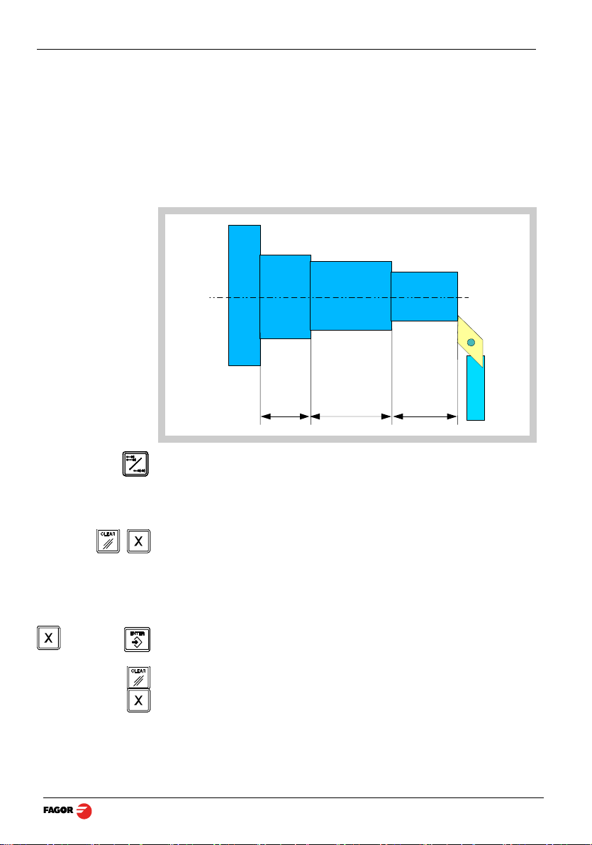
2.2.1 Example
In incremental
mode:
Using the lower figure, let us imagine we wish to make a part in which three
holes have to be drilled with the coordinates stated. It is clear that the
blueprint will only reflect the incremental coordinates (I) or the absolute ones
(ABS) referring to the part zero (point "0" in the figure) although the DRO also
shows them with respect to home (Io).
After referencing the axes, as was described in the previous section, we can
make this part in incremental or absolute mode according to whether we
chose a type of dimensions (I) or (ABS) of the blue-print.
[22.600
[22.600]
[0.000]
15.000
-Press this key until the ABS LED is turned off.
-Move the axis up to the face of the part to set it as part zero.
At this point, one can proceed in two ways:
-Preset the axis with a zero value by pressing this keystroke sequence:
-Move the axis towards the first position until the DRO reads: 22.600.
or...
-Preset the axis with a value of 22.600 by pressing this keystroke sequence.
In case of a mistake, press this key to cancel it and leave it as it was.
Pressing this key displays the previous preset value.
- Move the axis towards the first position until the DRO reads: 0.000.
This last method turns out to be more practical as after selecting the
destination coordinate one only has to remember to move the axis until the
DRO reads zero.
V0612 - 20i-T / 30i-T - Installation/Operation - DRO operation - (7/32)
22.60025.000
Page 8
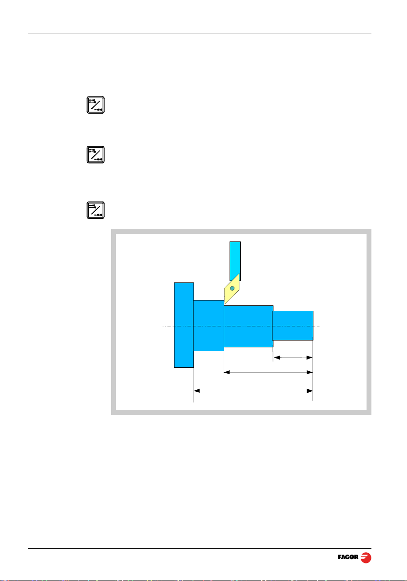
[25.000]
[0.000]
Note:
ABS
In absolute mode:
ABS
ABS
- Once this turning operation has concluded, one can go to the next position,
after having preset the next coordinate (25.000), by moving the axis until the
display reads 0.000.
- And so on until all the turning operations are concluded.
By pressing this key until the ABS LED lights up, the DRO will show the real
position of the axis with respect to part zero "0"
-Press this key until the ABS LED is turned on.
-To preset part zero:
-Place the axis exactly over “0” and press:
At any time, by pressing this key, the DRO will display the present position
with respect with the previous zero (ABS led on).
(8/32) - DRO operation - Installation/Operation - 20i-T / 30i-T - V0612
22.600
47.600
63.600
Page 9
2.3 Machine Reference selection and search
Although it is not absolutely necessary, it is recommended to use the
reference marks (Io) of the feedback system in order to set a machine zero
point.
This allows the user to reference the machine axes and restore the work
coordinates after having turned the dro off, moved the machine while the dro
was off, for safety or for any other reason.
Fagor linear encoders have reference marks every 50 mm all along its length.
In order to use these marks properly, choose an area on the axis, for example
in the middle of the measuring length or at one end. Approach this area and
carry out the home search. Once the reference mark has been found, mark
this area with a marker or sticker in order to carry out the home search in the
same area in later occasions and make sure that you are using the same
machine zero point (home).
Fagor also offers encoders with distance-coded reference marks every 20, 40
or 100 mm. When using these distance-coded reference marks, there is no
need to move to the 0 position to find the references, simply move a distance
equal to the gap between marks (20, 40 or 100 mm depending on the linear
encoder)
When using an absolute encoder, there is no need to search for the reference
marks (home).
The dro stores in its internal memory work coordinates such as machine zero,
absolute and incremental.
2.3.1 Home search sequence
For encoders with regular reference marks, move the axis to the home area.
Access or exit the home search mode.
The axis displays blink showing " r " if the axis has not been homed or
" r on" if it has been homed.
Select the axis to be referenced (homed)
The selected axis blinks until a reference mark is detected. The reference
signal presets the axis display automatically with the value of PAR10, 0.000
mm by default.
If the encoder does not have a reference mark, move the axis to the desired
position and press this key.
V0612 - 20i-T / 30i-T - Installation/Operation - DRO operation - (9/32)
Page 10
2.4 Operation with tools
2.4.1 Tool Preset
Up to 20 tools may be preset on this DRO model (from "tool 0" to "tool 19").
The unit stores in its internal memory the relative offsets of all the tools with
respect to that of "T0".
Therefore, if "T0" has been preset in ABS mode (on X and Z) and, then, the
rest of the tools, it will suffice to just preset "T0" again (on Z) to make a new
part. The DRO will then automatically recalculate all the offsets of the rest of
the tools without having to preset them for each part.
To preset a tool, just follow this procedure:
ABS
Notes: The presets done with any tool in incremental mode change the part zero for
- Place a part of known diameter in the chuck in absolute mode (ABS led on).
- Move the tool to be preset until it touches the part.
- Press this key. The 3rd display shows the word "tool" followed by the
number of the active tool.
- Enter the tool number.
- Press [ENTER] to validate this operation or [C] to cancel it.
- Preset the part diameter.
These tool presets are kept in memory even when the unit is powered off up
to a maximum of 10 years.
all the tools.
If a tool offset has been preset in Z
the same mode (Z
The tool offsets are referred to the machine zero found at the time. When
turning the DRO on, it is necessary to find the same reference mark.
The calculator function can also be used to preset an axis with the result of
the calculation. See section 2.5.5 Calculator.
, Z2 or Zs) when using it to machine the part.
1
, Z2 or Zs mode, that tool must be used in
1
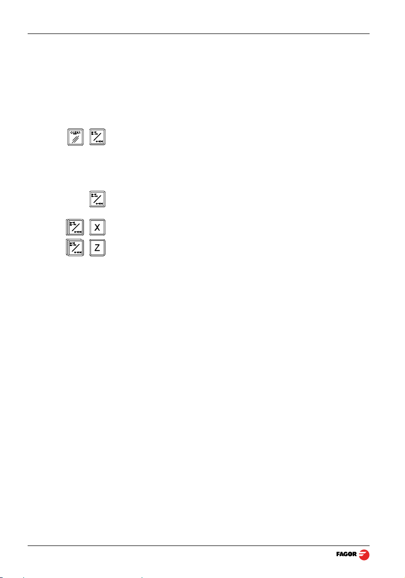
2.4.2 Deleting all tool offsets
To delete the offsets of ALL the tools. Press this keystroke sequence: It will
show the text: "Delete?",
Press [ENTER] to validate the operation or [C] to cancel it.
(10/32) - DRO operation - Installation/Operation - 20i-T / 30i-T - V0612
Page 11

2.5 Special operations
2.5.1 Scaling factor
It is possible to apply a scaling factor within ±9.999 for mold making
applications:
[factor]
The DRO will then show the axis position resulting from multiplying its real
position by the 'value' of the scaling factor.
2.5.2 To access the special functions (Hold, taper calculation, calculator)
Pressing [F] accesses the "special functions" menu.
This key may be used to display the various available options.
Pressing [ENTER] assumes the selected option.
Options: 1 - HOLD
2 - Angle calculation
3 - Calculator
Note:
A function may be directly accessed by pressing [F] and then the function
number. That is, [F] [1] to access HOLD directly or [F] [2] for angle
calculation.
2.5.3 Coordinate freeze (HOLD).
It enables “freezing” the display of the counter whilst inside it goes on reading
the real position of the axis. This comes about when it is necessary to change
the tool and preset the dimension of the new one.
Tool preset in HOLD mode.
It is possible to preset on the X axis the actual diameter value of the machined
part (measured with caliper or micrometer).
Procedure:
Having selected a tool:
• Machine the part to any diameter.
• Without removing the tool, set the X axis in HOLD mode.
• Remove the tool and measure the resulting diameter.
Value
• Preset the part diameter. That value will be preset as the offset of the
selected tool.
• Exit the HOLD mode.
V0612 - 20i-T / 30i-T - Installation/Operation - DRO operation - (11/32)
Page 12

Tool change at any known point of the part:
α
- Touch the part with the tool.
- Go into HOLD mode. The reading for that axis freezes with the current
value.
- Remove the tool to be replaced and insert the new one.
- Approach the new tool to the “freezing” point and touch the part at that point.
- Press this key. The reading “unfreezes” and starts counting from the
previously “frozen” value.
If this key is pressed instead, the DRO will assume half the distance traveled
since [HOLD] was pressed. This is possible when "freezing" only one axis.
2.5.4 Taper (cone) calculation
This DRO calculates the taper angle (cone) of a part by simply touching two of
its points and using these keys.
To do this, follow this procedure:
- Move the tool until it touches the part at any point of the taper.
- Access the angle calculation mode.
- Touch the part with the tool at any other point of the taper.
- Press [ENTER] so the DRO calculates the angle or [C] to cancel the
operation.
The "X" axis display will show the angle in ten-thousandths of a degree
(0.0001º) and the "Z" axis display will do so in degrees, minutes and
seconds.
- Press any key to return to the regular display mode.
(12/32) - DRO operation - Installation/Operation - 20i-T / 30i-T - V0612
Page 13

2.5.5 Calculator
This feature may be used to carry out mathematical and trigonometric
operations as well as preset the desired axis with the result of the calculation
or use the coordinates of the axes to carry out math operations.
To access the calculator mode
To quit the calculator mode.
2.5.5.1 Operating with the calculator.
Enters the first operand in the X axis display
Enters the second operand in the Z axis display.
Toggles between the various operations:
Display Meaning Operation
ad Add Result = X + Z
su Subtract Result = X - Z
nu Multiply Result = X * Z
di Divide Result = X / Z
Basic operations
Toggles between the various trigonometric operations
Trigonometric operations
Display Meaning Operation
Sin Sine Result = Sin X
Cos Cosine Result = Cos X
Tan Tangent Result = Tan X
It carries out the operation and leaves the result on the X axis display.
V0612 - 20i-T / 30i-T - Installation/Operation - DRO operation - (13/32)
Page 14

2.5.5.2 Recall and Reset modes
Toggles between the recall and Preset modes.
RECALL mode The recall mode lets enter the current axis position into the calculator.
Enters the current position of the selected axis into the calculator. The [Z] key
for the Z
axis and the [Zs] key for the Z2 axis.
1
PRESET mode The preset mode lets preset the desired axis with the result of an operation.
Presets the selected axis with the result of the calculation. The [Z] key for the
Z
axis and the [Zs] key for the Z2 axis.
1
Example Calculate [Z
Display keys Operation Display
X = 25
Z = 10
X = 0
Z = 0
Z
= Ad
s
X = 10
Z = 0
Z
= Ad
s
X = 10
Z = 0
Z
= Ad
s
X = 10
Z = 5
Z
= di
s
X = 2
Z =
Z
= di
s
X = 2
Z = Preset
Z =
X = 25
Z = 2
Z
= di
s
position] / 5 and preset the Z axis with the result.
1
Example: calculator
Goes into calculator mode X = 0
Goes into RECALL mode
and enters the current
position in the Z axis.
5
3 times
Presets the divisor (5) X = 10
Selects the divide operation X = 10
Result in the X display (2) X = 2
Goes into Preset mode X = 2
Presets the Z
axis with the
1
result of the calculation.
Quits the calculator mode. X = 25
Z = 0
= Ad
Z
s
X = 10
Z = 0
Zs = Ad
Z = 5
Zs = Ad
Z = 5
Zs = di
Z =
Zs = di
Z = Preset
Zs =
X = 25
Z = 2
Z
= di
s
Z = 2
Zs =
(14/32) - DRO operation - Installation/Operation - 20i-T / 30i-T - V0612
Page 15

3.1 Installation of the built-in model
Dimensions of the enclosure hole for inserting the DRO
Built-in DRO insertion
3 DRO installation
Nut DIN 985
M4 Inox
Bolt ISO 7380
M4 x 10 Inox
V0612-20i-T / 30i-T - Installation/Operation - DRO installation - (15/32)
Page 16

3.2 Rear panel
On the back of the unit the following items may be found:
1. Three-prong power connector for AC and ground connection.
2. M6 mm terminal for general machine ground connection.
3. Mounting bracket
Some of the following connectors might not be available depending on specific
models:
X1.- SUB-D HD type 15-pin female connector for 1st axis feedback device.
X2.- SUB-D HD type 15-pin female connector for 2nd axis feedback device.
Not available at the 10i model.
X3.- SUB-D HD type 15-pin female connector for the third axis feedback
device. Only available at the 30i-M model.
UL seal
In order to comply with UL standards, this unit must be connected in the final
application using a listed detachable cord set (BLEZ) with a molded threeprong plug and a suitable fitting to be connected to the equipment, rated
minimum 300 V AC. The cord type shall be SO, SJO or STO. Suitable Strain
Relief means must be provided in the cord set to assure the connection of the
plug and the fitting.
CE seal (see "CE seal" page 27)
(16/32) - DRO installation - Installation/Operation - 20i-T / 30i-T - V0612
Page 17

WARNING
Do not handle the connectors while the unit is under power.
Before handling the connectors (mains, feedback, etc.) make sure that the
unit is not under power.
It is NOT enough to turn the display off by using the [on/off] key at the
keyboard
3.3 General technical characteristics
• Universal Power Supply between 100V AC and 240V AC ±10% at Mains
frequency between 45 Hz and 400 Hz. Between 120Vdc and 300 Vdc
• It withstands power outages of up to 20 milliseconds.
• 10-year memory backup of installation parameters when the unit is off.
• The operating temperature inside the DRO enclosure must be between 5º C
and 45º C (41ºF and 113ºF).
• The storage temperature inside the DRO enclosure must be -25º C and
+70º C (-13º F and 158º F).
• Maximum relative humidity: 95% non condensing at 45ºC (113ºF).
• Front Panel Sealing: IP54 (DIN 40050), Rear panel: IP4X (DIN40050)
except for built-in models in which case is: IP20.
3.4 Connections
3.4.1 Connection of the feedback systems
The feedback systems (linear or rotary encoders) are connected via SUB-D
HD type 15-pin female connectors: X1 through X3. The latter (for the 2nd
axis) is not available at the 10i model.
Characteristics of feedback inputs: X1, X2 and X3:
- Power consumption: 250 mA at the +5V input.
- Admits square-wave signal (TTL). (A, B, Io)
1
- Maximum frequency: 250 KHz, minimum gap between flanks: 950 nsec.
- Phase shift: 90º ±20º, hysteresis: 0.25 V, Vmax: 7V,
maximum input current: 3mA
- High threshold (logic state 1) 2.4V < VIH < 5V
- Low threshold (logic state 0) 0.0V < VIL < 0.55V
V0612-20i-T / 30i-T - Installation/Operation - DRO installation - (17/32)
Page 18

3.5 Easy setup
Feedback connection. Connectors X1, X2 and X3
Pin Signal Function
1A
2/A
3B
4/B
5I0
6 /I0
7Alarm
8/Alarm*
9 +5V Power supply to feedback devices
10 Not connected
11 0V Power supply to feedback devices
12, 13, 14 Not connected
15 Chassis Shield
The "Easy Setup" may be used to set up the feedback of the DRO and to
verify that the installation is correct and no feedback pulses are missed.
It sets up the encoder resolution and the kind of reference marks being used
as well as the positive counting (reading) direction.
Input for feedback signals
3.5.1 Accessing the "Easy Setup" mode
Press [CLEAR] [OFF]
CODE: 555
And, instead of entering the parameters accessing code, key in: 555
The axes displays will show “Setup” meaning that the feedback is not set up
yet.
3.5.2 Operating mode.
• Move the axis to the origin or zero point and press the axis key.
The display shows “START”.
• Move the axis in the positive direction all the way to the end of the travel so
the DRO can read as many reference marks as possible.
• Press [ENTER] to finish. The moving direction used will be assumed as the
positive direction.
(18/32) - DRO installation - Installation/Operation - 20i-T / 30i-T - V0612
Page 19

The axis status will then switch to one of the following:
Ready Correct feedback setup
Repeat Wrong feedback setup, the process should be repeated.
Error Error in the feedback system.
Note: If the feedback device is a steel tape type linear encoder, press [F] before
pressing [ENTER] so it is properly detected.
3.5.3 Power and machine connection
Always mount it vertically so its keyboard is within operator's reach and its
digits are easily visible (at operator's eye level).
Do not connect or disconnect the DRO connectors while it is under power.
Connect all metallic parts to a common point on the machine tool and it to the
general ground point. Use cables of enough gage (no thinner than 8 mm
for this connection.
3.6 Installation parameters
These DROs have a number of installation parameters to configure it for a
particular application.
The way these parameters are displayed depends on whether they are
general or particular for each axis.
• If it affects the axes, the parameter number (PAR??) appears on each axis
display and the corresponding axis key must be pressed to modify it.
• If it is a general parameter, the X display will show the parameter number
and the Z its current value; if there is only one axis, its number will appear
on the X display and, after pressing , its value.
There are several kinds of parameters depending on how to set them:
to
• With binary values, it only takes values of 0 or 1 for each digit. The value is
changed by pressing the key with the relevant digit between [1] and [8].
Where [1] corresponds to the rightmost digit of the display and [8] to the
leftmost digit.
• Numeric values, usually with the corresponding axis resolution, they are
entered as regular coordinate preset.
• Options; the value is changed by pressing this key which will make the
various options appear in a cyclic way.
2
)
V0612-20i-T / 30i-T - Installation/Operation - DRO installation - (19/32)
Page 20

To get into parameter editing
The dro displays must be on, reading mode and press the following keys:
CODE: 060496
The X axis display shows the word " COdE ". 060496
The displays of the DRO show PAR00.
Once in regular display mode, parameter PAR05 (scaling factor) may also
be recalled by pressing this keystroke sequence, so the work mode may be
changed without having to go through all the previous steps.
Note: Like PAR05, parameter PAR53 is directly accessible.
To enter a parameter
• Select axis.
[Value]
• Press this key to save the displayed value.
• Press this key to cancel the modification.
Move through parameters
Press the [ENTER] key to go on to the next parameter or ---
Press this key to return to the previous one.
To quit the parameter editing mode:
Press this key.
To go to a particular parameter:
PAR Nr
To go directly to a particular parameter without going through the previous
ones, (once in parameter editing mode) press this key sequence.
Then, select the axis affecting this parameter.
To recover the factory set default values for the installation parameters:
Once in parameter editing mode, displaying PAR00 on all the displays,
press this keystroke sequence. The dots of the first axis will light up.
(20/32) - DRO installation - Installation/Operation - 20i-T / 30i-T - V0612
Page 21

3.7 Parameters to configure axis position reading and display.
The digits of digital parameters refer to the digits on the axis displays so digit
"1" (that can be changed with the [1] key) corresponds to the rightmost digit
and "8" to the leftmost digit.
XXXXXXXX <-- binary code
87654321 <-- keys
PARA METER FUNCTION
PAR 00 Feedback configuration, different per axis, binary type.
This parameter sets the specific characteristics of the feedback device (rotary
or linear encoder) used to read the axis position.
Digit
8, 7, 6 Not being used at this time (they must be set to "0")
5 Feedback resolution units:
Linear axis: 0 = mm, 1 = inches
Note: These units refer to feedback pulses not to the position display.
4 Type of axis: They must be set to zero.
3 Not being used at this time
2 Not being used; it must be set to "0".
1 Counting direction (0 = normal, 1 = reverse)
If an axis count increases or decreases in the opposite direction to the one
desired, change the value of this digit.
PAR 01 Feedback resolution. Independent for each axis.
Possible values:
Linear axis:From 0.0001 mm up to 1.0000 mm (0.000005" to 0.03937")
Rotary axis:From 0.0001º to 1.0000º (from 1 to 999 seconds).
Factory setting: 0.0050 mm (5 µm).
Formula to calculate encoder resolution:
R
360
--------------------------------------------------------------
p TTLfactor Sfactor××
360
---------------------------------------------------==
pPAR02 PAR03××
Where:
R = Resolution in degrees
p = Pulses per turn of the encoder
TTLfactor = Multiplying factor for TTL signal
Sfactor = Multiplying factor for sinusoidal signal
V0612-20i-T / 30i-T - Installation/Operation - DRO installation - (21/32)
Page 22

PAR02 TTL multiplying factor (subdivision). Independent for each axis.
Options: x4, x2, x1 and x0.5.
The factory setting is x4 and it is the one used for FAGOR linear encoders.
When using rotary encoders on linear axes, it should be calculating according
to the number of pulses of the encoder, leadscrew pitch and the desired
resolution as per the formula:
P
p
----------=
RxF
Where:
p = Pulses per turn of the encoder
P = Leadscrew pitch in mm/turn
R = Resolution in mm/pulse
F = Multiplying factor to be applied.
PAR03 External multiplying factor when using distance-coded reference marks or
TTL signals.
Independent for each axis. It is not required when using absolute feedback.
Options: 1, 5, 10, 20, 25, 50.
Factory setting: 1
Feedback parameters
Signal Model
MT / MKT
TTL
TTL dif.
CT
FT
MTD
MX / MKX
CX
SX
GX
FX
LX
MOX
COX
SOX
GOX
FOX 25 00X01010
LOX 10 00X00110
PAR00
XXXXXXXX
0000000X
PAR01
mm
0.005
0.001
PAR02 PAR03 PAR14
X 00X0XX00
4
5 00X00010
Note: In the table, X means that the bit is irrelevant.
(22/32) - DRO installation - Installation/Operation - 20i-T / 30i-T - V0612
Page 23

PAR 04 Axis display. Independent for each axis.
Digit
8, 7, 6, 5, 4 Not being used at this time (they must be set to "0"),
3 Turn the axis display off. 0 = No, 1 = Yes.
2 Axis display toggle radius/diameter
0 = no toggle, 1 = toggle
1 Axis display. 0 = radius, 1 = diameters. When it does not toggle.
PAR 05 Shrink or scaling factor independent for each axis.
Numeric value within ±9.999.
A "0" value means that no factor is to be applied. It is not applied when
reading with respect to machine reference cero (its LED on) or onto the tool
when applying tool compensation (TOOL led on).
The factory setting is “0”.
PAR 08 Use of alarms.
Indicates whether the alarms for feedrate, travel limits and feedback will be
activated or not.
Digit
8, 7, 6, 5 Not being used at this time (they must be set to “0”)
4 Active value of the feedback alarm. (0=low, 1=high)
3 Detect feedback alarm provided by the linear encoder. 0 = No, 1 = Yes.
2 Detect travel limits (PAR12 and PAR13).When this alarm is activated, the
axis value blinks.
The blinking axis error is cleared by returning the axis within its limits
1 Detect feedback speed alarm when exceeding 200Khz (60m/min with a
resolution of 1µm). Not applicable to a rotary axis.
Possible values: 0 (alarms off) and "1" (alarms on).
Factory-set (default) values: 0
Feedback and feedrate alarms are shown with (. . . . . . . .) at the display.
The speed alarm is cleared by pressing this key.
PAR 09 Linear compensation of a machine axis. Independent for each linear axis.
Numeric value within ±99.999 millimeters per meter.
Factory setting: 0.
Notes: Even when selecting the display in inches, this value MUST ALWAYS BE IN
MILLIMETERS.
When a rotary axis, the setting of this parameter will be ignored.
1 inch = 25.4 mm
PAR 10 Offset of the reference point with respect to the reference zero of the scale,
independent for each axis.
Usually, the machine reference zero (reference mark of the linear encoder)
does not coincide with the absolute zero to be used.
V0612-20i-T / 30i-T - Installation/Operation - DRO installation - (23/32)
Page 24

Therefore, when using standard Io's, this parameter must be assigned the
value of the distance from the machine zero point to the feedback reference
point.
Numeric value in resolution units for each axis.
Factory setting: 0.
This value will be in mm or inches depending on whether the INCH LED is off
or on.
PAR11 Personalize.
Digit
8 Display the feedrate of the moving axis (only for the 30i-T)
7 Operate always in mm.
6 Operate always in inches.
5 Do not display "Fagor DRO" on power-up.
4 If =0, normal zero setting and coordinate presetting (factory set)
If =1, quick zeroing of the position value displayed on each axis.
3 If =1, allow the selection of the work plane for bolt-hole drilling
2 Not being used; it must be set to "0".
1 The key affects one axis ( = 0) or both ( = 1).
If it affects each axis independently, after pressing this key, one must press
the axis key.
It may toggle from absolute reading mode to incremental. This parameter
determines whether this toggle affects one axis or both. Factory setting: "1".
PAR 1 2, PAR1 3 Travel limit.
To set the negative axis travel limit.
Both parameters admit any value.
This value will be in mm or inches depending on whether the INCH LED is off
or on.
If PAR08 bit 2 = 1, when the axis exceeds the travel distance between both
parameters, the relevant display starts blinking until it is positioned within
these limits.
PAR14 Binary type home search setting.
Digit
8, 7 Not being used at this time (they must be set to "0")
6 If =1, it indicates mandatory home search on power-up.
5 Direction of the distance-coded Io ( 0 = Increasing , 1 = Decreasing).
4 1 = Pitch of the distance-coded Io 100 mm, 0 = 20 mm
3 1 = Pitch of the distance-coded Io: 40 mm. 0 = 20 mm
2 Type of Io of the linear encoder. (0 = fixed, 1 = distance-coded).
1 If =1, Linear encoder without I0. To carry out a home search when the
feedback device does not have a reference mark “Io”, this parameter must be
set to “1”.
Factory setting: "0".
(24/32) - DRO installation - Installation/Operation - 20i-T / 30i-T - V0612
Page 25

PAR 15 Multi-point leadscrew error compensation.
Important: Before capturing data for an accuracy graph, the axis (axes) must be
homed (referenced) because the compensation will not be applied until they
are homed. To use this compensation, it is recommended to set PAR 14 so
as to force a mandatory home search on power-up.
7
6
5
4
3
2
1
0
1
1 2 3 4 5 6 7
2
3
4
5
6
7
The compensation point must have at least one point with no error
Multi-point leadscrew error compensation table (in mm)
Point Nr. Position
10 0
2 200.000 0.002
3 275.250 0.007
4 427.345 -0.005
5 700.500 -0.007
6 760.000 0.003
7 1015.000 0.006
(error 0).
V0612-20i-T / 30i-T - Installation/Operation - DRO installation - (25/32)
Error to be
compensated
Page 26

or
POS 1
ERROR 1
Select the desired axis and enter the number of points to be used for the axis,
up to 40. Zero means that there is no compensation table for the axis.
Where “POS 1” is the point number to enter and “ERROR 1” the amount of
error to be compensated.
Pressing [ENTER] displays the position value (X axis display) and the amount
of error to be compensated (Z axis display).
[Pos Nr]
[Error]
Error to be compensated = Master's actual position - displayed position
It goes on to edit the next point.
PAR20 It sets the configuration of the axes.
Digit
8 Turn the feedback off after 2 minutes in "DISPLAY OFF" mode.
7 The displays turn off if none of the axis has moved in 30 minutes. Pressing
any key or moving any of the axes turns the displays back on.
6 - 1 Not being used at this time. They must be set to “0”
PAR53 Select the number of decimals to be displayed.
Possible values:0.0 to 6.6 .
The first digit corresponds to the number of decimals to be displayed in mm
and the second digit to the number of decimals in inches.
When selecting a “0” value or a value greater than the number of decimals of
PAR01 it will display the factory set number of decimals.
Note: It has no effect on rotary axes.
PAR65 It enables various functions of the dro.
Digit
8, 7, 6 Not being used at this time.
5 1= To directly access parameter PAR05.
4 Not being used at this time.
3 1 = Enables the buzzer. It beeps when pressing any key.
2 To access the special functions (Hold, taper calculation)
1 It enables this key.
(26/32) - DRO installation - Installation/Operation - 20i-T / 30i-T - V0612
Page 27

4 Appendix
4.1 UL seal
See "UL seal" page 16.
4.2 CE seal
Warning
Before starting up the DRO, carefully read the instructions of Chapter 2 in
the Installation Manual.
The DRO must not be powered-on until verifying that the machine complies
with the "89/392/CEE" Directive.
4.2.1 Declaration of conformity
Manufacturer: Fagor Automation, S. Coop.
Barrio de San Andrés 19, C.P. 20500, Mondragón -Guipúzcoa (ESPAÑA)
We hereby declare, under our responsibility that the product:
Fagor Digital Readout:
20i-T, 30i-T
meets the following directives:
SAFETY: EN 60204-1Machine safety. Electrical equipment of the machines
ELECTROMAGNETIC COMPATIBILITY:
EN 61000-6-4 Emission
EN 55011 Radiated. Class A, Group 1.
EN 55011 Conducted. Class A, Group 1.
EN 61000-3-2 Harmonics
EN 61000-3-3 Flickers.
EN 61000-6-2 Immunity
EN 61000-4-2 Electrostatic discharges.
EN 61000-4-3 Radiofrequency Radiated Electromagnetic Fields.
EN 61000-4-4 Bursts and fast transients.
EN 61000-4-5 Shockwaves
EN 61000-4-6 Conducted disturbance induced by radio frequency fields.
EN 61000-4-8 Magnetic fields at mains frequency
EN 61000-4-11 Voltage fluctuations and Outages.
ENV 50204 Electromagnetic fields radiated by wireless telephones.
As instructed by the European Community Directives on Low Voltage:
73/23/EEC, (and the 93/68/EEC amendment) on Machine Safety 89/392/EEC
and 89/336/EEC on Electromagnetic Compatibility.
In Mondragón, April 1st, 2005
V0612 - 20i-T / 30i-T - Installation/Operation - Appendix - (27/32)
Page 28

32
4.2.2 Safety conditions
Read the following safety measures in order to prevent damage to personnel,
to this product and to those products connected to it.
Fagor Automation shall not be held responsible for any physical or material
damage derived from the violation of these basic safety regulations.
Do not manipulate the inside of the unit
Only personnel authorized by Fagor Automation may manipulate the inside of
this unit.
Do not handle the connectors while the unit is under power.
Before handling the connectors (mains, feedback, etc.) make sure that the
unit is not under power.
Use proper Mains AC power cables.
To avoid risks, use only the Mains AC cables recommended for this unit.
Avoid electrical overloads
In order to avoid electrical discharges and fire hazards, do not apply electrical
voltage outside the range indicated in chapter 2 of this manual
Ground connection
In order to avoid electrical discharges, connect the ground terminals of all the
modules to the main ground terminal. Before connecting the inputs and
outputs of this unit, make sure that all the grounding connections are properly
made.
Before powering the unit up, make sure that it is connected to ground
In order to avoid electrical discharges, make sure that all the grounding
connections are properly made.
Ambient conditions
Respect the limits for temperature and relative humidity indicated in chapter
"General technical characteristics" page 17
Do not work in explosive environments
In order to avoid risks, damage, do not work in explosive environments.
Work environment
This unit is ready to be used in Industrial Environments complying with the
directives and regulations effective in the European Community.
(28/32) - Appendix - Installation/Operation - 20i-T / 30i-T - V0612
Page 29

It is recommended to mount the DRO vertically,
so its power switch of the back panel is at a distance between 0.7 m (27.5
inches) and 1.7 m (5.6 ft) off the floor and away from coolants, chemical
products, blows etc that could damage it. Keep it away from direct sunlight,
extremely hot air, high voltage and high current sources as well as from
relays, or high electromagnetic fields (about 0.5 m or 20 inches).
This unit complies with the European directives on electromagnetic
compatibility. Nevertheless, it is recommended to keep it away from sources
of electromagnetic disturbance such as.
- Powerful loads connected to the same AC power line as this equipment.
- Nearby portable transmitters (Radio-telephones, Ham radio transmitters).
- Nearby radio / TC transmitters.
- Nearby arc welding machines.
- Nearby High Voltage power lines.
- Disturbance generating elements of the machine.
-Etc.
Safety symbols Symbols which may appear on the manual
WARNING symbol.
It has an associated text indicating those actions or operations may hurt
people or damage products.
Symbols that may be carried on the product
WARNING symbol.
It has an associated text indicating those actions or operations may hurt
people or damage products.
“Electrical shock” symbol.
It indicates that point may be under electrical voltage.
"Ground Protection" symbol.
It indicates that point must be connected to the main ground point of the
machine as protection for people and units.
V0612 - 20i-T / 30i-T - Installation/Operation - Appendix - (29/32)
Page 30

32
4.2.3 Warranty terms
WARRANTY All products manufactured or marketed by Fagor Automation has a warranty
period of 12 months from the day they are shipped out of our warehouses.
The mentioned warranty covers repair material and labor costs, at FAGOR
facilities, incurred in the repair of the products.
Within the warranty period, Fagor will repair or replace the products verified
as being defective.
FAGOR is committed to repairing or replacing its products from the time when
the first such product was launched up to 8 years after such product has
disappeared from the product catalog.
It is entirely up to FAGOR to determine whether a repair is to be considered
under warranty.
EXCLUDING
CLAUSES
SERVICE
CONTRACTS
The repair will take place at our facilities. Therefore, all shipping expenses as
well as travelling expenses incurred by technical personnel are NOT under
warranty even when the unit is under warranty.
This warranty will be applied so long as the equipment has been installed
according to the instructions, it has not been mistreated or damaged by
accident or negligence and has been manipulated by personnel authorized by
FAGOR.
If once the service call or repair has been completed, the cause of the failure
is not to be blamed the FAGOR product, the customer must cover all
generated expenses according to current fees.
No other implicit or explicit warranty is covered and FAGOR AUTOMATION
shall not be held responsible, under any circumstances, of the damage which
could be originated.
Service and Maintenance Contracts are available for the customer within the
warranty period as well as outside of it.
4.2.4 Material returning terms
When returning the DRO, pack it in its original package and with its original
packaging material. If not available, pack it as follows:
Get a cardboard box whose three inside dimensions are at least 15 cm (6
inches) larger than those of the unit. The cardboard being used to make the
box must have a resistance of 170 Kg (375 lb.).
When sending it to a Fagor Automation office for repair, attach a label
indicating the owner of the unit, person to contact, type of unit, serial number,
symptom and a brief description of the problem.
Wrap the unit in a polyethylene roll or similar material to protect it.
Pad the unit inside the cardboard box with polyurethane foam on all sides.
Seal the cardboard box with packing tape or industrial staples.
(30/32) - Appendix - Installation/Operation - 20i-T / 30i-T - V0612
Page 31

4.3 Error codes
Error codes
Error Description
FAGOR dro Power outage or turned off with main switch after saving the data.
Error 02 The unit has been turned off without previously pressing [ON/OFF]. It only looses
Error 04 Wrong parameter data
Error 05 Wrong internal configuration
Error 06 Errors in data backup memory (Service Dept.)
Error 07 Emergency input active. Press [CLEAR] or cancel the emergency signal.
Error 08 Wrong software memory or the software has been changed.
Error 09 Errors in work memory (Service Dept.)
Error 12 Error while searching a distance-coded reference mark (Io).
Error 31 Internal malfunction (Service Dept.).
Error 32 Internal malfunction (Service Dept.).
Error 99 Internal malfunction (Service Dept.).
. . . . . . . . Feedback alarm coming from the feedback device (linear or rotary encoder).
1. 4. 3. 6. 5. 7. 2. 5 Feedback speed too high.
EEEEEEEE Maximum position reading or speed exceeded when searching home.
feedback reading (it resets it to zero and the status of the operating modes, inch,
abs, radius, etc.).
If any message other than the first two from the table were to come up, the
equipment should be switched off and on again until one of the first two are
seen.
After pressing this key to access the counting mode, check the parameters.
If any of the errors shown as (Service Department) are often repeated, ask
Fagor Automation’s Customer Services Department about this.
If the display of any axis shows all its dots; for example: 1.4.3.6.5.7.2.5. It
means that the axis has been moved too fast (>200 KHz or 60 m/min with 1
µm resolution). This error will be displayed if the alarm activation parameter
for the axis PAR08(1) = 1
To clear the display, press this key.
If the axis value is flashing, this means that one of the travel limits established
by machine parameter has been exceeded. This error will be displayed if the
alarm activation parameter for the axis PAR08(2) = 1
If the DRO does not come on or goes out while running, check that the
voltage and ground outlets are as they should be. If there are OK, disconnect
the feedback connectors one by one. If the dro comes on, it means a
feedback failure. If the fault persists get in touch with Fagor Automation’s
Customer Services Department about it.
V0612 - 20i-T / 30i-T - Installation/Operation - Appendix - (31/32)
Page 32

32
4.4 Maintenance
Cleaning: An accumulation of dirt in the equipment can act as a screen preventing
Preventive
Inspection
proper dissipation of the heat generated by the internal electronic circuits with
the consequent danger of overheating and DRO fault.
Accumulated dirt can also, in some cases, provide a conductive path for
electricity which could give rise to faults in the internal circuits of the
equipment, especially in high humidity conditions.
To clean the equipment nonabrasive dish-washing detergents are
recommended (in liquid, never powder form) or 75% isotropic alcohol with a
clean cloth. DO NOT USE aggressive solvents, (benzol, acetones, etc.)
which could damage the materials the equipment is made with.
Do not use high pressure compressed air to clean the item as this could give
rise to an accumulation of charges which in turn lead to electrostatic
discharges.
The plastics used in the front panel of the DRO stand up to:
• Grease and mineral oils.
• Alkalis and bleaches.
• Dissolved Detergents.
• Alcohol
Avoid the effect of solvents such as Chlorohydrocarbons, Benzol, Esters and
Ethers because these could damage the plastics with which the front of the
equipment is made.
If the DRO does not come on press the rear switch for starting, make sure it is
properly connected and being supplied with the proper mains voltage.
FAGOR AUTOMATION S. COOP.
Bª San Andrés Nº 19
Apdo de correos 144
20500 Arrasate/Mondragón
- Spain -
Web: www.fagorautomation.com
Email: info@fagorautomation.es
Tel.: (34) 943 719200
Fax: (34) 943 791712
(32/32) - Appendix - Installation/Operation - 20i-T / 30i-T - V0612
Fagor Automation S. Coop.
 Loading...