

Page 1
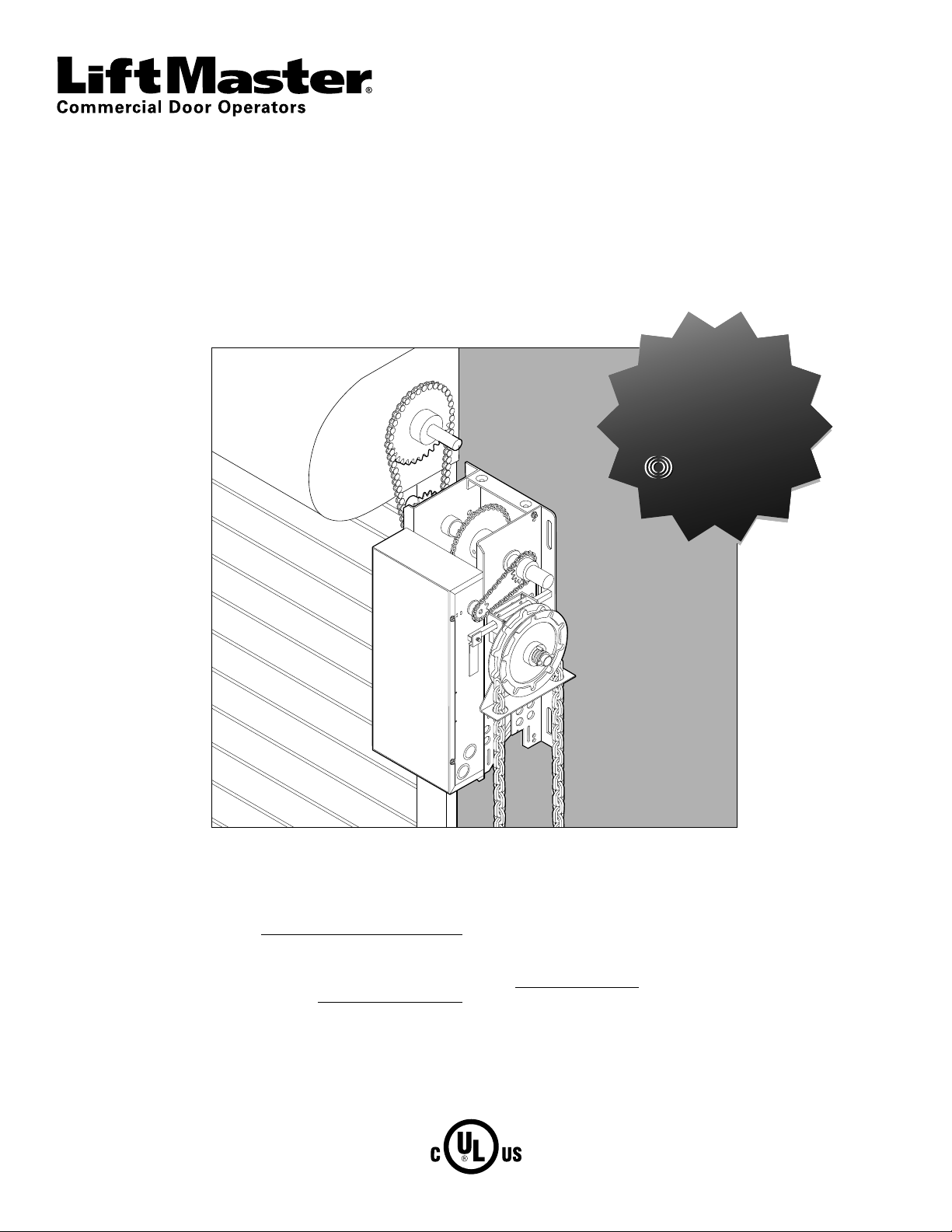
MEDIUM DUTY DOOR OPERATOR
MODELS MJ5011U, MH5011U, MHS5011U, & MGJ5011U
INSTALLATION MANUAL
Now with
Now with
Now with
Now with
Now with
Now with
Built in
Built in
Built in
Built in
Built in
Built in
Radio Receiver
Radio Receiver
Radio Receiver
Radio Receiver
Radio Receiver
Radio Receiver
315 MHz
315 MHz
315 MHz
315 MHz
315 MHz
315 MHz
Your model may look different than the model illustrated in this manual.
2 YEAR WARRANTY
Serial #
(located on electrical box cover)
Installation Date
NOT FOR RESIDENTIAL USE
THIS PRODUCT IS TO BE
INSTALLED AND SERVICED BY A
TRAINED DOOR SYSTEMS
TECHNICIAN ONLY.
Visit www.liftmaster.com to locate a
professional installing dealer in your area.
OPERATOR RATING: 12 cycles per hour,
50 cycles per day; maximum
Page 2

TABLE OF CONTENTS
SAFETY INFORMATION 3
APPLICATION 4
OPERATOR SPECIFICATIONS 5-6
Weights and Dimensions . . . . . . . . . . . . . . . . . . . 5
Motor . . . . . . . . . . . . . . . . . . . . . . . . . . . . . 6
Mechanical. . . . . . . . . . . . . . . . . . . . . . . . . . . 6
Electrical . . . . . . . . . . . . . . . . . . . . . . . . . . . . 6
Safety . . . . . . . . . . . . . . . . . . . . . . . . . . . . . 6
Environmental . . . . . . . . . . . . . . . . . . . . . . . . . 6
CARTON INVENTORY 6
PREPARATION 7
Preparing Your Door. . . . . . . . . . . . . . . . . . . . . . 7
Handing Identifi cation . . . . . . . . . . . . . . . . . . . . . 7
ASSEMBLY 7
TYPICAL INSTALLATION 8-14
Determine Mounting Location for Operator . . . . . . . . . . 8
Install the Operator . . . . . . . . . . . . . . . . . . . . . 8-9
Install Emergency Disconnect System . . . . . . . . . . . . .10
Power and Ground Wiring Connections . . . . . . . . . . 11-12
Install 3-Button Control Station . . . . . . . . . . . . . . 12-13
Setup Radio Antenna . . . . . . . . . . . . . . . . . . . 13-14
ADJUSTMENT 15
Adjust the Limits. . . . . . . . . . . . . . . . . . . . . . . .15
Adjust the Clutch. . . . . . . . . . . . . . . . . . . . . . . .15
ENTRAPMENT PROTECTION 16-19
LiftMaster Monitored Entrapment Protection (LMEP) . . . . .16
Install the Photoelectric Sensors. . . . . . . . . . . . . . . .17
Mount the Photoelectric Sensors . . . . . . . . . . . . . . .18
Entrapment Protection Wiring Options . . . . . . . . . . 18-19
LOGIC BOARD LAYOUT 19
BASIC PROGRAMMING 20-23
Determine the Wiring Type . . . . . . . . . . . . . . . . 20-21
Remote Controls. . . . . . . . . . . . . . . . . . . . . . 21-22
Timer-to-Close (TTC) . . . . . . . . . . . . . . . . . . . 22-23
TESTING 23
EMERGENCY DISCONNECT 24
TROUBLESHOOTING 25-26
DIAGRAM 26
ACCESSORIES 27
CONTROL CONNECTION DIAGRAM BACK COVER
2
Page 3
SAFETY INFORMATION
WARNING WARNING
WARNING
WARNING WARNING
WARNING
CAUTION CAUTION
WARNING
WARNING
WARNING
WARNING
WARNING
Mechanical
Electrical
When you see these Safety Symbols and Signal Words on the
following pages, they will alert you to the possibility of serious
injury or death if you do not comply with the warnings that
accompany them. The hazard may come from something
mechanical or from electric shock. Read the warnings carefully.
IMPORTANT INSTALLATION INSTRUCTIONS
When you see this Signal Word on the following pages, it will
alert you to the possibility of damage to your door and/or the door
operator if you do not comply with the cautionary statements that
accompany it. Read them carefully.
IMPORTANT NOTES:
• BEFORE attempting to install, operate or maintain the operator,
you must read and fully understand this manual and follow all
safety instructions.
• DO NOT attempt repair or service of your commercial door and
gate operator unless you are an Authorized Service Technician.
WARNING
To reduce the risk of SEVERE INJURY or DEATH:
1. READ AND FOLLOW ALL INSTALLATION WARNINGS AND
INSTRUCTIONS.
2. Install door operator ONLY on properly balanced and
lubricated door. An improperly balanced door may NOT
reverse when required and could result in SEVERE INJURY or
DEATH.
3. ALL repairs to cables, spring assemblies and other hardware
MUST be made by a trained door systems technician BEFORE
installing operator.
4. Disable ALL locks and remove ALL ropes connected to door
BEFORE installing operator to avoid entanglement.
5. Install door operator 8 feet (2.44 m) or more above fl oor.
6. NEVER connect door operator to power source until
instructed to do so.
7. NEVER wear watches, rings or loose clothing while installing
or servicing operator. They could be caught in door or
operator mechanisms.
8. Install control station:
• within sight of the door.
• out of reach of children at minimum height of
5 feet (1.5 m).
• away from ALL moving parts of the door.
9. Install the control station far enough from the door to
prevent the user from coming in contact with the door while
operating the controls.
10. Install the entrapment warning placard on wall next to the
control station in a prominent location that is visible from
the door.
11. Place manual release/safety reverse test label in plain view
on inside of door.
12. Upon completion of installation, test entrapment protection
device.
13.
SAVE THESE INSTRUCTIONS.
3
Page 4
APPLICATION
This operator includes a number of features that will provide years
of reliable and safe operation.
FEATURES:
• Supports both monitored and non-monitored entrapment
protection devices: Entrapment protection devices detect
obstructions in the door's path and automatically reverse a
closing door.
• Radio receiver: A factory installed radio receiver allows remote
controls, keyless entries and other remote command devices to
be programmed to the operator.
• Timer-To-Close: The Timer-to-Close feature allows the door to
automatically close after a preset time (only available with B2
wiring and a monitored entrapment protection device).
• Wiring Types: The functionality of the operator is based on the
wiring type. The operator is shipped from the factory in standard
C2 wiring type (factory default). Some wiring types will require
an optional monitored entrapment protection device. Refer to
Basic Programming Section for descriptions of wiring types,
requirements and programming.
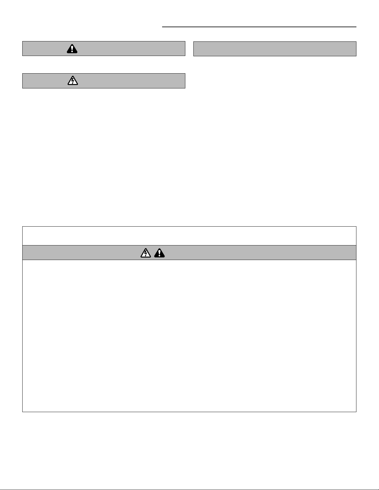
Photoelectric Sensors
Intended for use on vertical or high-lift sectional doors, or rolling door products. The MHS operator is recommended for rolling sheet
doors. Not recommended for use on a standard lift sectional door.
MAXIMUM DOOR AREA (SQUARE FEET)
24 ga. Steel 22 ga. Steel
Aluminum Grilles
---
ROLLING DOOR
---
Fiberglass
---
SECTIONAL DOOR
Aluminum Doors
24 ga. Steel
24 ga.
22 ga. Steel
Aluminum Doors
---
---
---
20 ga. Steel
20 ga. Steel
Wood Doors
24 ga. Steel
Insulated
20 ga. Steel
18 ga. Steel
---
---
---
---
---
16 ga. Steel
20 ga. Steel
Insulated
16 ga. Steel
---
20 ga. Steel
Insulated
16 ga. Steel
Insulated
---
---
16 ga. Steel
Insulated
320
SQ. FT
NOTE: On steel insulated doors, a 24 ga. Back panel is assumed.
275 250 200
160
4
120
Page 5
A
A
A
A
B
B
B
B
OPERATOR SPECIFICATIONS
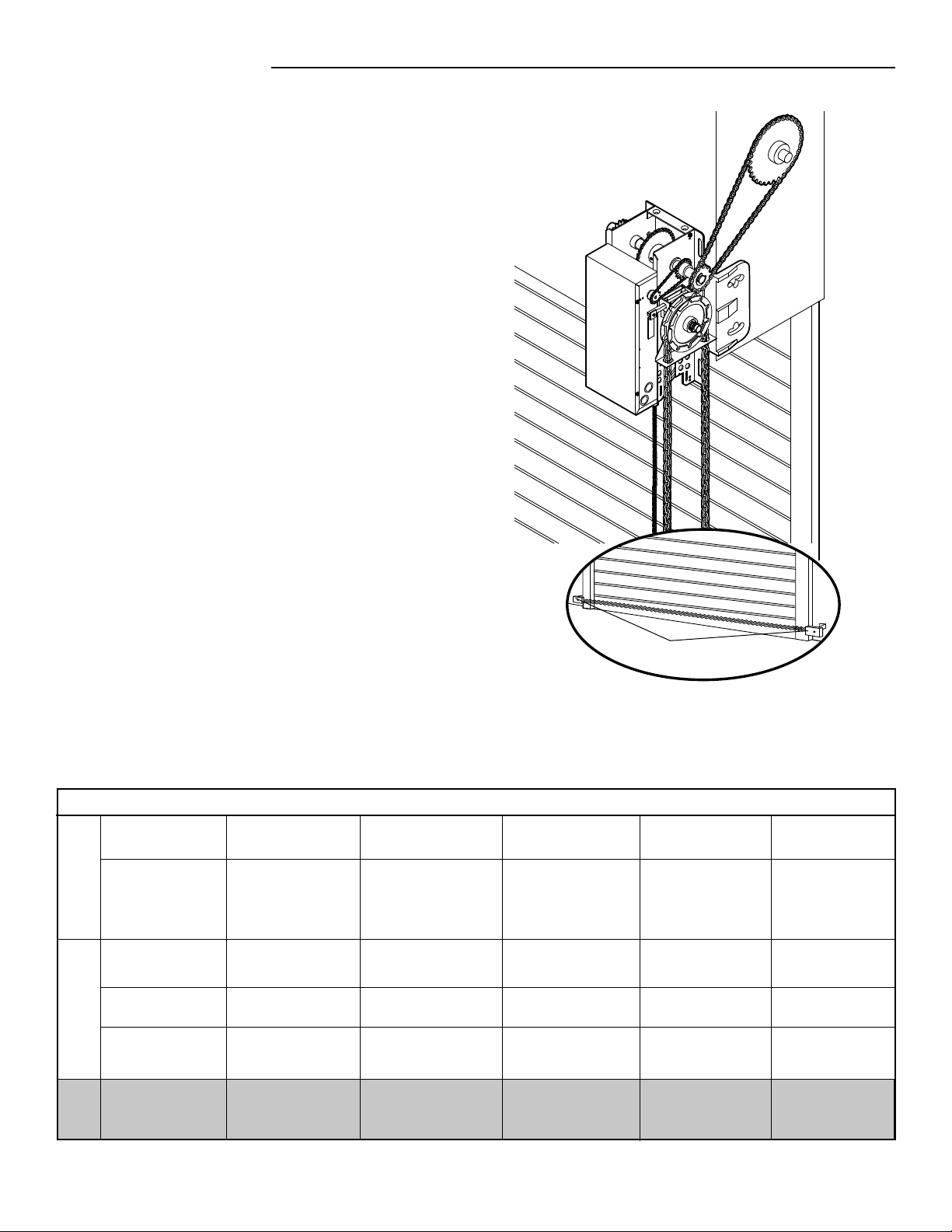
WEIGHTS AND DIMENSIONS
MODELS MH, MJ, AND MHS
Hanging Weight: 60-70 LBS. (27.22-31.75 kg)
6.34"
(16.1 cm)
(30.86 cm)
12.69"
(32.23 cm)
7.19"
(18.26 cm)
12.15"
15.78"
(40.03 cm)
6.34"
(16.1 cm)
6.13"
(15.57 cm)
9.19"
(23.34 cm)
3.25"
(8.26 cm)
3.1"
(7.87 cm)
18.87"
(47.93 cm)
Hand Chain Wheel present
with Model MH only.
6.5"
(16.51 cm)
MOUNTING DIMENSIONS
A - Wall Mounting
B - Bracket Mounting (rolling door)
14.75"
(37.47 cm)
7"
(17.78 cm)
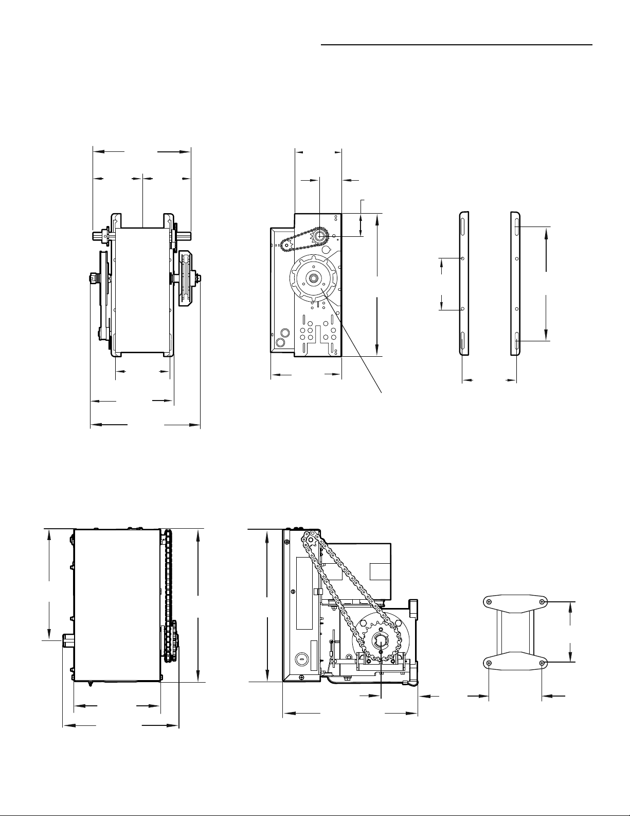
MODEL MGJ ONLY
Hanging Weight: 60 LBS. (27.22 kg)
9.196"
(23.36 cm)
7.00"
(17.78 cm)
9.25"
(23.50 cm)
12.62"
(32.05 cm)
12.56"
(31.90 cm)
MOUNTING DIMENSIONS
11.00"
(27.94 cm)
3.00"
(7.62 cm)
4.75"
(12.07 cm)
5.50"
(13.97 cm)
5
Page 6
OPERATOR SPECIFICATIONS
^
OPEN
^
CLOSE
O
STOP
MOTOR
TYPE: . . . . . . . . . . . . . . . . . . . . . . . . . . . . . . . . . . . . . Limited duty
HORSEPOWER: . . . . . . . . . . . . . . . . . . . . . . . . . . . . . . . . . . 1/2 HP
VOLTAGE: . . . . . . . . . . . . . . . . . . . . . 115 Vac, Single Phase, 60 Hz
OPERATOR
CURRENT (Amperage):
Voltage-Phase . . . . . . . . . . . . . . . . . . . . . . . . . . . . . . . . . . 1/2 HP
115-1Ø, 60Hz . . . . . . . . . . . . . . . . . . . . . . . . . . . . . . . . . . . . 11.2
MECHANICAL
DOOR SPEED:. . . . . . . . . . . . . . Approximately 9" (23 cm) / second
depending on door setup
OUTPUT FORCE:. . . . . . . . . . . . . . . . . . . . . . . . . .125 ft. lbs / sec.
MGJ ONLY . . . . . . . . . . . . . . . . . . . . . . . . . . . . 40 ft. lbs / sec.
OUTPUT RPM:
MJ. . . . . . . . . . . . . . . . . . . . . . . . . . . . . . . . . . . . . . . . . 80 RPM
MH . . . . . . . . . . . . . . . . . . . . . . . . . . . . . . . . . . . . . . . . 80 RPM
MHS . . . . . . . . . . . . . . . . . . . . . . . . . . . . . . . . . . . . . 38.6 RPM
MGJ . . . . . . . . . . . . . . . . . . . . . . . . . . . . . . . . . . . . . . . 23 RPM
LIMIT ADJUST:. . . . . . . . . . . . Fully adjustable up to 14' door Max
DUTY: . . . . . . . . . . . . . . . . . . . . . . . . . . . . 12 Cycles per Hour Max
50 Cycles per Day Max
DRIVE TRAIN:. . . . . . . . . . . . . . . . . . . . Maintenance Free Bearings
MGJ ONLY . . . . . . . . . . . . . . . . . . . Maintenance Free Bearings
Wormgear-in-Oil-Bath Reducer
FINISH: . . . . . . . . . . . . . Powder coated, Corrosion Resistant Steel
ELECTRICAL
OPERATOR VOLTAGE: . . . . . . . . . . . 115 Vac, Single Phase, 60 Hz
WIRING TYPE: . . . . . . . . . . . . . . . . C2 (Standard) B2 Configurable
(See Basic Programming Section)
CONTROL WIRING: . . . . . . . . . . . . . . . . . . . . . . . . . . . 16-22 AWG
SAFETY
DISCONNECT:
MH . . . . . . . . . . . . . . . . . . . . . . . . . . Floor level chain hoist for
manual chain hoist operation.
MJ. . . . . . . . . . . . . . . . . . . . . . . . . . . Floor level disconnect for
manual operation.
MHS . . . . Both MH and MJ type disconnects described above.
MGJ . . . . . . . . . . . . . . . . . . . . . . . . . Floor level disconnect for
manual operation.
ENTRAPMENT PROTECTION:
LiftMaster Monitored Entrapment Protection (LMEP)
Photoelectric Sensors (CPS-U): . . . . . . . . . . . . . . . Through beam
used to provide non-contact safety protection.
Safety Edge (Optional): . . . . . . . . . Electric or pneumatic sensing
device attached to the bottom edge of door.
(see Accessory Page 27)
ENVIRONMENTAL
LOCATION: . . . . . . . . . . . . . . . . . . . . . . . . . . . .Indoor, dry location
OPERATING TEMPERATURE: . . . . . . . . . . . . . . . . .-4˚ F to + 122˚ F
(-20˚ C to + 50˚ C)
UL Listed to 40˚ C: Chamberlain tested to 50˚ C
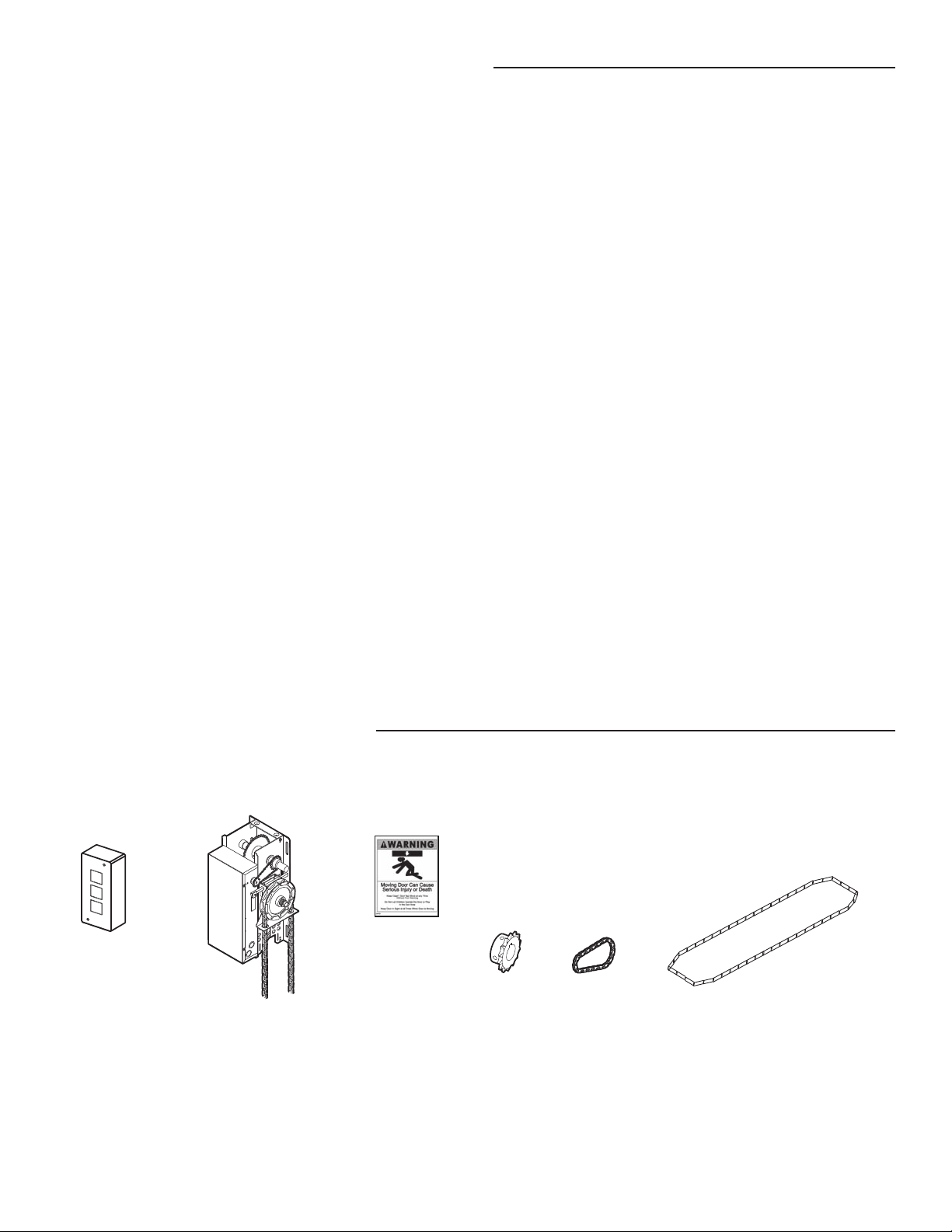
CARTON INVENTORY
Before beginning your installation check that all components were provided. Your model may look different than the model illustrated.
Warning Placard
3-Button Station
Operator
Operator Drive
Sprocket
NOT SHOWN
Installation Manual
Quickstart Guide
User’s Guide
Entrapment Warning Placard
Installation Hardware Bag, Complete with: Master links (2), Wall bracket (1), Fastener Bag (1)
Door sprocket
6
Door/Operator
Chain
Hoist Hand Chain
Models MH and MHS ONLY
Page 7
PREPARATION
PREPARING YOUR DOOR
The manufacturer recommends 3 feet (91.4 cm) of clearance in front of operator for serviceability. Before you begin:
• Disable locks.
• Remove any ropes connected to door.
• Before the operator is installed, be sure the door has been properly aligned and is working smoothly. Although each installation will
vary due to particular building characteristics, refer to the following general procedures to install the operator.
HANDING IDENTIFICATION
For MH and MHS models with manual hoist hand chain systems,
the handing of the operator must be determined at the time of
order. The handing is indicated by last letter of the model name
(R or L). The illustration shown is a right-handed operator for
models MJ and MHS series only. Left-handed operator will have
hoist chain on the left side.
The hand chain wheel can not be switched on site. If your
installation causes the hand chain to hang in the door opening,
hook the chain off to the side near the top of the door jamb.
RIGHT-HANDED OPERATOR
MODEL SHOWN: MH5011UR
Output Shaft
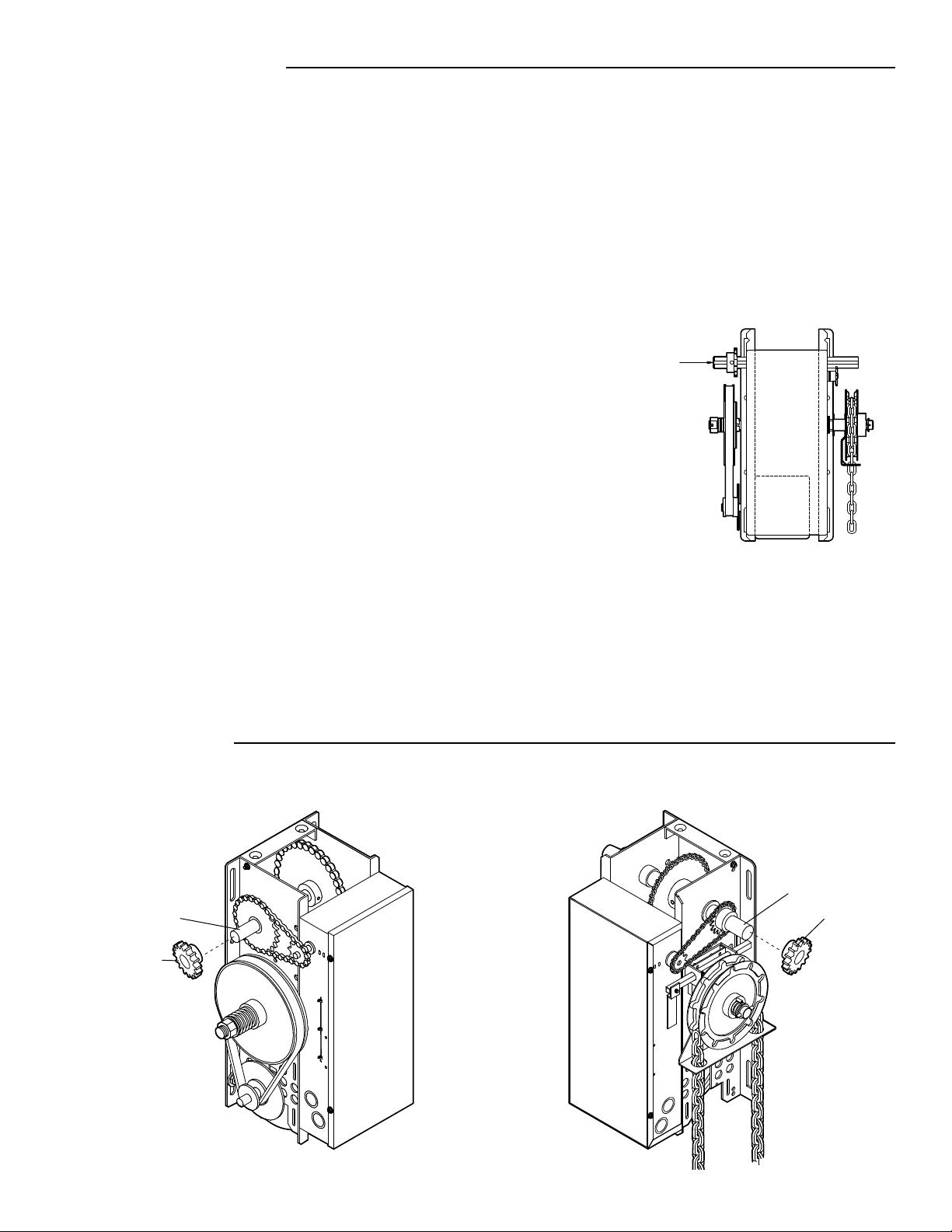
ASSEMBLY
Install operator drive sprocket.
1
RIGHT-HAND ASSEMBLY
Drive Shaft
Operator Drive
Sprocket
LEFT-HAND ASSEMBLY
Drive Shaft
Operator Drive
Sprocket
7
Page 8
TYPICAL INSTALLATION
NOTE: The illustrations may not depict your installation.
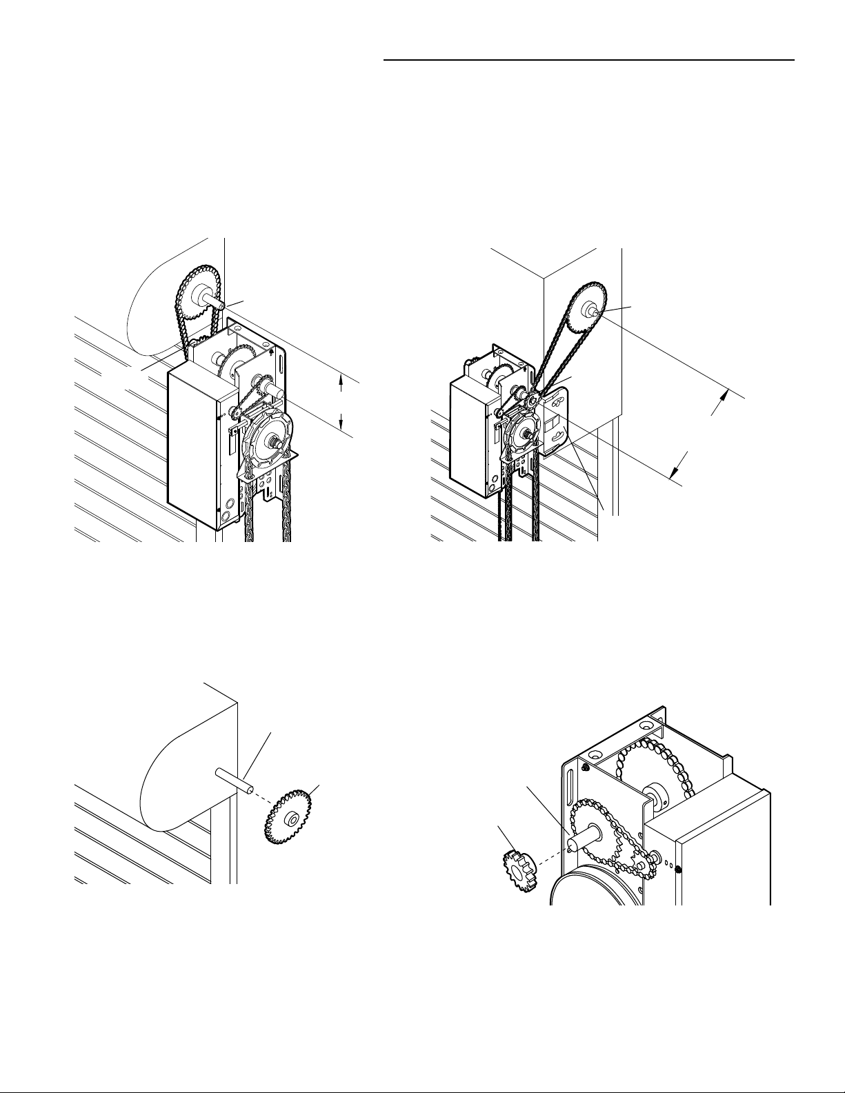
DETERMINE MOUNTING LOCATION FOR OPERATOR
The operator may be mounted on the wall, shelf or bracket (not provided, see accessories or door manufacturer). The optimum
distance between the door shaft and operator drive shaft is 12-15 inches.
WALL MOUNT
Door Shaft
Operator
Drive Shaft
INSTALL THE OPERATOR
SHELF OR BRACKET MOUNTING
Door Shaft
Operator
Drive Shaft
Optimum Distance
12"-15"
Optimum Distance
12"-15"
Optional Mounting Bracket.
See Accessories.
Place door sprocket on door shaft.
1
Door Shaft
Door Sprocket
Place operator door sprocket on operator.
2
Drive Shaft
Operator Drive
Sprocket
8
Page 9
TYPICAL INSTALLATION
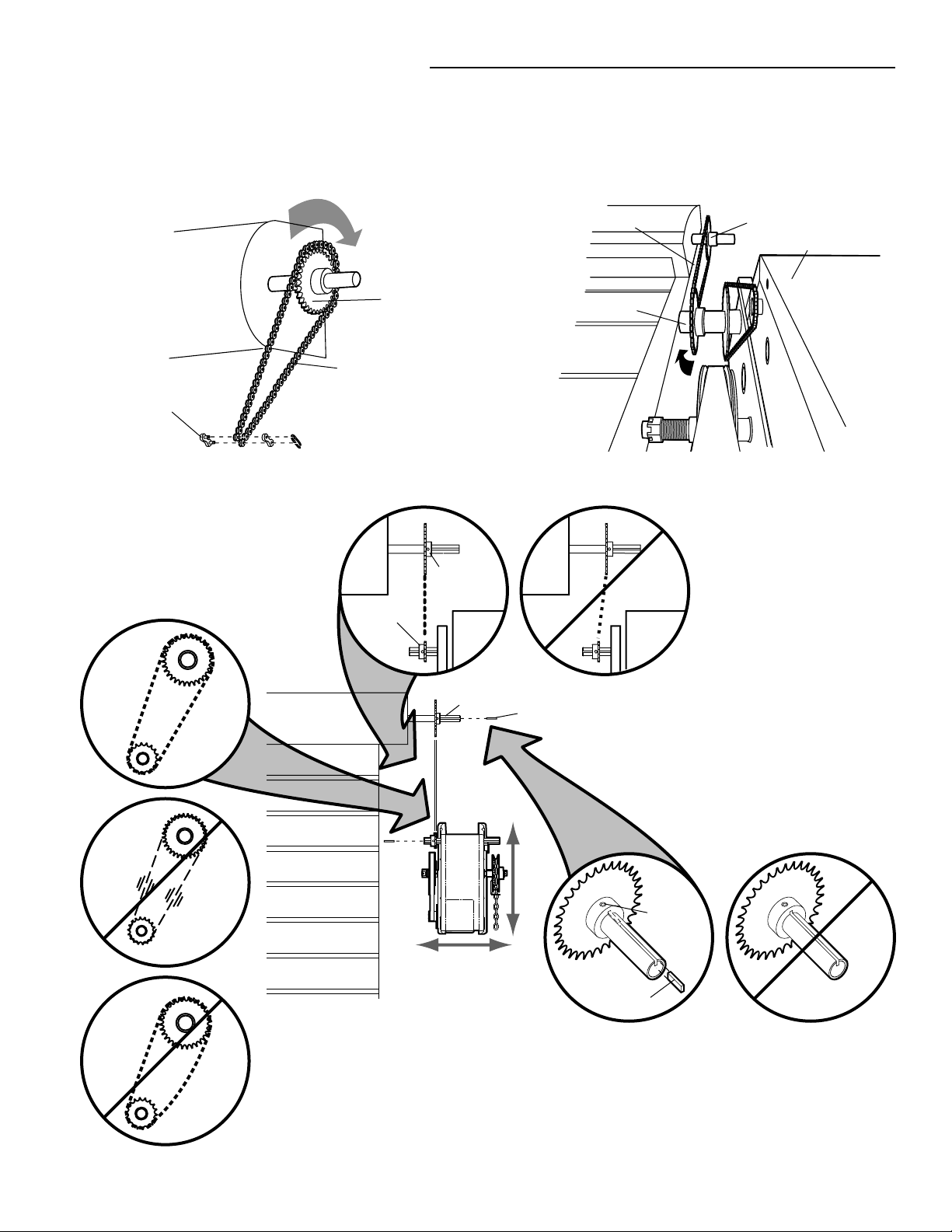
INSTALL THE OPERATOR
Wrap drive chain around door sprocket.
34
Door Sprocket
Drive Chain
Master Link
Position the operator until chain is taut
5
(not tight). If chain is too tight, it may
cause damage to operator.
Operator Drive
Sprocket
Door Sprocket
Wrap drive chain around operator sprocket.
Drive Chain
Operator Drive
Sprocket
Door Sprocket
Electrical Box
Door
Door Sprocket
7
8
Keep door sprocket and operator door
6
Key
sprocket aligned. If sprockets are not
aligned, they may cause premature
wear on the chain.
Set Screw
Key
Secure both sprockets with key and set screw. If sprockets
are not secure, they may drift and cause damage to operator.
Secure operator to mounting surface using appropriate
method and hardware. Mounting template can be found on
carton.
9
Page 10

TYPICAL INSTALLATION
INSTALL EMERGENCY DISCONNECT SYSTEM
MODELS MH AND MHS ONLY
The MHS operator includes both a floor level disconnect sash
chain to disconnect the door from the door operator that allows
manual push up operation and an additional sash chain to engage
the manual chain hoist that also electrically disables the operator
controls.
Secure chain retaining bracket to wall 4 feet above the floor.
1
Wrap hand chain around hand chain wheel and through chain
2
guide.
Connect the ends of the hand chain.
3
Hand Chain
Wheel
Chain Retaining
Bracket
(with pad locking
provisions)
Hand
Chain
MODELS MJ AND MGJ ONLY
Secure keyhole bracket to wall 4 feet above the floor.
1
Keyhole Bracket
4' above
floor
Floor
4'
2'
10
Page 11

TYPICAL INSTALLATION
WARNING
WARNING WARNING
POWER AND GROUND WIRING CONNECTIONS
To reduce the risk of SEVERE INJURY or DEATH:
• ANY maintenance to the operator or in the area near the
operator MUST NOT be performed until disconnecting the
electrical power and locking-out the power. Upon completion
of maintenance the area MUST be cleared and secured, at that
time the unit may be returned to service.
• Disconnect power at the fuse box BEFORE proceeding.
Operator MUST be properly grounded and connected in
accordance with local electrical codes. The operator should be
on a separate fused line of adequate capacity.
NOTE: Power and control wiring must be run in separate conduit
in accordance with national and local electrical codes. Must use 14
AWG or heavier wire for power wiring. Use conduit knockouts for
wiring as indicated on the electrical box labels.
IMPORTANT NOTE: Operator must be properly grounded. Failure
to properly ground the operator could result in electric shock and
serious injury.
• ALL electrical connections MUST be made by a qualifi ed
• DO NOT install ANY wiring or attempt to run the operator
• ALL power wiring should be on a dedicated circuit and well
• ALL power and control wiring MUST be run in separate
DISTANCE GAUGE
50 feet 14 AWG
100 feet 12 AWG
200 feet 8 AWG*
350 feet 6 AWG*
500 feet 4 AWG*
1000 feet 2 AWG*
individual.
without consulting the wiring diagram.
protected. The location of the power disconnect should be
visible and clearly labeled.
conduit.
POWER WIRING CHART
DO NOT turn power on until you have fi nished making ALL power
and control wiring connections.
Remove cover.
1
Electrical Box Cover
Maximum wire gauge that can be connected to the operator’s
*
terminal is 12 AWG. When a larger wire gauge is required, the
wire must be gauged down to 12 AWG. USE COPPER WIRE ONLY.
Run power wires to electrical box according to national and
2
local electrical codes.
Electrical Box
Sealing Nut
(Not Provided)
Conduit
11
Page 12

TYPICAL INSTALLATION
^
O
OPEN
STOP
^
CLOSE
^
O
OPEN
STOP
^
CLOSE
WARNING
WARNING WARNING
POWER AND GROUND WIRING CONNECTIONS
Attach power and ground wires to terminals.
3
Power
Hot
Neutral
Ground
Line Power 115 Vac Single Phase
INSTALL 3-BUTTON CONTROL STATION
To prevent possible SERIOUS INJURY or DEATH from
electrocution:
• Be sure power is NOT connected BEFORE installing door
control.
To prevent possible SERIOUS INJURY or DEATH from a closing
door:
• Install door control within sight of door, out of reach of
children at a minimum height of 5 feet (1.5 m) and away from
ALL moving parts of door.
• Install the control station far enough from the door to prevent
the user from coming in contact with the door while operating
the controls.
• Install the entrapment warning placard on wall next to the
• NEVER permit children to operate or play with door control
• Activate door ONLY when it can be seen clearly, is properly
• ALWAYS keep door in sight until completely closed. NEVER
Control
control station in a prominent location that is visible from the
door.
push buttons or remote controls.
adjusted and there are no obstructions to door travel.
permit anyone to cross path of closing door.
Remove the control station cover.
1
Fasten the control station to the wall at least 5 feet above the
2
ground. The installation surface must be smooth and fl at.
Screws
Wall
Ground
5'
(1.5 m)
3-Button Control
Station
Select appropriate knockout and run the wires to the operator.
3
Conduit
OPEN
^
^
CLOSE
O
STOP
Knockout
12
Page 13

AUXANT
^^^^
AUXANT
AUX ANT
D14
COMINTRLK STOP
LED
OPENCLOSE
TYPICAL INSTALLATION
INSTALL 3-BUTTON CONTROL STATION
Connect wires to the control station and replace the control
4
station cover.
Power
LEARN
STOP CLOSE OPEN
TTC
1
234567
LMEP1LMEP2
Control
Logic Board
Remove factory
jumper if
external
interlock is
used.
TTC
R27
1
LMEP1 LMEP2
LEARN
D14
LED
23 45 67
STOP CLOSE OPEN
COM INTRLK STOP
OPENCLOSE
Stop
Close
Open
Fasten the entrapment warning placard next to the control
5
station.
UL
Entrapment
Placard
Warning Placard
OPEN
^
^
CLOSE
O
STOP
Common
SETUP RADIO ANTENNA
OPTION A
Locate the wire antenna on the outside of the electrical
1
box. Cut the wire tie closest to the edge of the
electrical box.
3-Button Control
Station
Press the plastic standoff into the hole in the side of
2
the electrical box.
Antenna
Wire Ties
Standoff
Cut this Wire Tie
Cut Wire Tie
Antenna
13
Page 14

TYPICAL INSTALLATION
WARNING
WARNING
WARNING WARNING
SETUP RADIO ANTENNA
OPTION B
Locate the wire antenna on the outside of the electrical box.
1
Cut wire ties and discard standoff.
Cut these Wire Ties
NOTICE: To comply with FCC and or Industry Canada (IC) rules, adjustment or modifications of this receiver and/or transmitter are prohibited, except for changing the code setting or replacing the battery.
THERE ARE NO OTHER USER SERVICEABLE PARTS.
Tested to Comply with FCC Standards FOR HOME OR OFFICE USE. Operation is subject to the following two conditions: (1) this device may not cause harmful interference, and (2) this device must accept any
interference received, including interference that may cause undesired operation.
Attach the antenna to the electrical box using the wire tie
2
holes. Bend antenna across the front of the electrical box,
ensuring that the antenna is 4 inches away from the front of
the electrical box.
Wire Ties
Antenna
Cut Wire Ties
IMPORTANT SAFETY INSTRUCTIONS
To reduce the risk of SEVERE INJURY or DEATH:
1. READ AND FOLLOW ALL WARNINGS AND INSTRUCTIONS.
2. ALWAYS keep remote controls out of reach of children.
NEVER permit children to operate or play with door control
push buttons or remote controls.
3. ONLY activate door when it can be seen clearly, it is properly
adjusted and there are no obstructions to door travel.
4. ALWAYS keep door in sight until completely closed. NO ONE
SHOULD CROSS THE PATH OF THE MOVING DOOR.
5. NO ONE SHODULD GO UNDER A STOPPED, PARTIALLY
OPENED DOOR.
6. If possible, use manual release handle to disengage door
ONLY when door is CLOSED. Weak or broken springs or
unbalanced door could result in an open door falling rapidly
and/or unexpectedly.
7. NEVER use manual release handle unless doorway is clear of
persons and obstructions.
8. After ANY adjustments are made, the entrapment protection
device MUST be tested.
9. Entrapment Protection device MUST be tested every month.
10. ALWAYS KEEP DOOR PROPERLY BALANCED. An
improperly balanced door may NOT reverse when required
and could result in SEVERE INJURY or DEATH.
11. ALL repairs to cables, spring assemblies and other
hardware, ALL of which are under EXTREME tension, MUST
be made by a trained door systems technician.
12. ALWAYS disconnect electric power to door operator BEFORE
making ANY repairs or removing covers.
13.
SAVE THESE INSTRUCTIONS.
14
Page 15

A B
ADJUSTMENT
WARNING
WARNING WARNING
ADJUST THE LIMITS
To avoid SERIOUS personal INJURY or DEATH from
electrocution:
Depress retaining plate. Adjust OPEN limit. Adjust CLOSE limit.
123
Retaining Plate
OPEN Limit Nut
OPEN Limit Switch
CLOSE Limit Nut
CLOSE Limit Switch
Door Travel
SAFETY Limit Switch
NOTE: When retaining plate is released, verify that the retaining plate is fully seated with the notches of the limit nut.
• Disconnect electric power BEFORE performing ANY
adjustments or maintenance.
Decrease
Door Travel
Increase
Increase
Door Travel
Decrease
Door Travel
ADJUST THE CLUTCH
FOR MODELS MJ, MH, AND MHS ONLY
Apply power to operator.
1
Turn clutch nut to release tension.
2
Re-tighten nut until there is just enough tension to permit
3
smooth operation.
Replace cotter pin. Bend ends of cotter pin to secure
4
clutch nut.
To Loosen
Clutch Nut
To Tighten
15
Page 16

WARNING
WARNING
—
ENTRAPMENT PROTECTION
LIFTMASTER MONITORED ENTRAPMENT PROTECTION (LMEP)
IMPORTANT INFORMATION ABOUT THE LIFTMASTER
MONITORED ENTRAPMENT PROTECTION DEVICES
A LiftMaster Monitored Entrapment Protection (LMEP) device is
required for most wiring types. If a LiftMaster Monitored
Entrapment Protection device is not installed, constant pressure to
close will be required from the control station.
When properly connected and aligned, the photoelectric sensors
will detect an obstruction in the path of its invisible light beam. If
an obstruction breaks the light beam while the door is closing, the
door will stop and typically reverse to the full open position.
The photoelectric sensors must be installed facing each other
across the door, no more than 6" (15 cm) above the floor.
Each photoelectric sensor has an LED that will glow steady when
the sensor is properly connected and aligned. The LEDs on both
photoelectric sensors will flicker rapidly when obstructed or
misaligned.
WARNING
To prevent possible SERIOUS INJURY or DEATH from a closing
door:
• Be sure power is NOT connected to the door operator
BEFORE installing the photoelectric sensor.
• The door MUST be in the fully opened or closed position
BEFORE installing the LiftMaster Monitored Entrapment
Protection device.
To prevent SERIOUS INJURY, DEATH, ENTRAPMENT, or
PROPERTY DAMAGE:
• Correctly connect and align the photoelectric sensor.
• Install the photoelectric sensor beam NO HIGHER than
6" (15 cm) above the fl oor.
• This is a required safety device for B2, TS, T, and FSTS wiring
types and MUST NOT be disabled. For D1, C2, and E2 wiring
the installation of an entrapment device is recommended.
• LiftMaster Monitored Entrapment Protection devices are for
use with LiftMaster Commercial Door Operators ONLY. Use
with ANY other product voids the warranty.
• If an edge sensor is being used on a horizontal slide door,
then place one or more edge sensors on both the leading and
trailing edge.
• If an edge sensor is being used on a vertically moving door,
then place one or more edge sensors on the bottom edge of
the door.
—Left Side of Garage—
Photoelectric
Safety Reversing
Sensor 6" (15 cm)
Sensor
max. above fl oor
16
Invisible Light Beam
Invisible Light Beam
Protection Area
Protection Area
— Right Side of Garage
Photoelectric
Safety Reversing
Sensor
Sensor 6" (15 cm)
max. above fl oor
Page 17

ENTRAPMENT PROTECTION
INSTALL THE PHOTOELECTRIC SENSORS
The following instructions show recommended assembly of the bracket(s) and “C” wrap based on the wall installation of the
photoelectric sensors on each side of the door or on the door tracks themselves. There are also alternate mounting methods which may
fi t your installation requirements better.
Make sure the wraps and brackets are aligned so the photoelectric sensors will face each other across the door.
Fasten the “C” wraps to the mounting brackets having square
1
holes, using hardware shown.
WALL INSTALLATION
Connect each assembly to a slotted bracket, using the
2
hardware shown. Note alignment of brackets for left and
right sides of the door.
3
Finger tighten the lock nuts.
Use bracket mounting holes as a template to locate and drill
4
(2) 3/16" diameter pilot holes on both sides of the garage
door, 4-6 inches (10-15 cm) above the fl oor. Do not exceed
6 inches (15 cm).
5
Attach bracket assemblies with 1/4"x1-1/2" lag screws.
#10-32
Lock Nuts
DOOR TRACK INSTALLATION
Discard slotted bracket. Drill 3/8" holes in each track and
2
fasten securely with hardware .
Door Track
Drill 3/8" Holes
Mounting Bracket
with Square Holes
Inside
Wall
“C” Wrap
#10-32x3/8"
Screws
1/4" Lock Nuts
“C” Wrap
Adjust right and left side bracket assemblies to the same
6
distance out from mounting surface. Make sure all door
hardware obstructions are cleared. Tighten the nuts securely.
1/4"x1-1/2"
Lag Screws
Inside
Wall
Mounting Bracket
with Slot
1/4"-20
Lock Nuts
1/4"-20x1/2" Carriage Bolts
(with square shoulders)
“C” Wrap
Mounting Bracket with
Square Holes
ALTERNATE WALL INSTALLATION
Inside
Wall
Mounting Bracket with Slot
Mounting Bracket with Square Holes
“C” Wrap
Sensor with Wire
- Floor -
Indicator Light
Mounting Bracket with
Square Holes
1/4"-20x1/2"
Carriage Bolts
ALTERNATE FLOOR INSTALLATION
Inside
Sensor with Wire
Wall
“C” Wrap
- Floor -
Indicator Light
Mounting Bracket with
Square Holes
Mounting Bracket with Slot
Attach with Concrete Anchors
(Not Provided)
17
Page 18

^^^^
XANT
ANT
D14
COM INTRLK STOP
LED
OPENCLOSE
TTC
LEARN
1
LMEP1 LMEP2
234567
STOP CLOSE OPEN
ENTRAPMENT PROTECTION
MOUNT THE PHOTOELECTRIC SENSORS
Center each sensor in the bracket with the lenses pointing
1
toward each other across the door.
Attach the sensors to the brackets with the provided
2
hardware. Finger tighten the receiving sensor wing nut.
Securely tighten the sending sensor wing nut.
Wing Nut
“C” Wrap
Wire
Indicator Light
Run the wires from both sensors to the operator. Use
3
insulated staples to secure wire to the wall and ceiling.
Connect the sensor wires to the operator.
4
Bell Wire
Photoelectric Sensor
6" (15 cm) max. above floor
Invisible Light Beam Protection Area
Sensor
Photoelectric Sensor
6" (15 cm) max. above floor
1/4"-20x1-1/2" Hex Bolt
Secure wire with
insulated staples
Connect wire
to Operator
ENTRAPMENT PROTECTION WIRING OPTIONS
PRIMARY INSTALLATION: CPS-U PHOTOELECTRIC SENSORS
(White)
(White/Black)
NOTE: When installing model CPS-UN4, connect the brown wire to
terminal 1 and the blue wire to terminal 2.
18
Page 19

ENTRAPMENT PROTECTION
^^^^
AUX ANT
AUX ANT
D14
COM INTRLK STOP
LED
OPENCLOSE
TTC
LEARN
1
LMEP1 LMEP2
234567
STOP CLOSE OPEN
^^^^
AUX ANT
AUX ANT
D14
COM INTRLK STOP
LED
OPENCLOSE
TTC
LEARN
1
LMEP1 LMEP2
2345 67
STOP CLOSE OPEN
^^^^
AUX ANT
AUX ANT
D14
COM INTRLK STOP
LED
OPENCLOSE
TTC
LEARN
1
LMEP1 LMEP2
2345 67
STOP CLOSE OPEN
ENTRAPMENT PROTECTION WIRING OPTIONS
ALTERNATE INSTALLATIONS:
CPS-U PHOTOELECTRIC SENSOR WITH 2-WIRE SENSING EDGE
2-wire electric or pneumatic sensing edge
(White)
(White/Black)
CPS-U PHOTOELECTRIC SENSOR WITH 4-WIRE SENSING EDGE
4-wire electric sensing edge
(White/Black)
(White)
2-WIRE ELECTRIC OR PNEUMATIC SENSING EDGE (B2 NOT AVAILABLE)
2-wire electric or pneumatic sensing edge
(White/Black)
LOGIC BOARD LAYOUT
ITEM DESCRIPTION FUNCTION
1 Open Button Open Door
2 Close Button Close Door
3 Stop Button Stop Door
4 Learn Button Programs the remote controls
and performs additional
programming
5 Timer-to-Close Button Programs the Timer-to-Close
6 Purple Wire Antenna Primary Antenna
7 Auxiliary Antenna Connection For use with external antenna
8 LED Used during programming
9 Field Wiring Terminal Field wiring connections
10 Factory Wiring Connector Factory wiring harness
kit -EXT-ANT. Not Provided
and diagnosing error codes
connection
(White)
3
2
STOP CLOSE OPEN
OPENCLOSE
9
1
10
5
4
6
7
TTC
D14
LED
1
2345 67
COM INTRLK STOP
LMEP1 LMEP2
LEARN
^^^^
AUX ANT
AUX ANT
8
19
Page 20

BASIC PROGRAMMING
DETERMINE THE WIRING TYPE
The functionality of this operator is based on the wiring type. The operator is shipped from the factory in standard C2 wiring type
(factory default). LIFTMASTER MONITORED ENTRAPMENT PROTECTION (LMEP) DEVICE IS RECOMMENDED.
A LiftMaster Entrapment Protection (LMEP) device is required for any momentary contact to close mode of operation including B2,
TTC and remote controls.
NOTES:
• The LED on the logic board will blink once when in C2 and twice when in B2.
• The operator will automatically convert to B2 wiring when Monitored Entrapment Protection Device is installed. If the Monitored
Entrapment Protection Device is blocked or removed, the operator will go into a Restricted Close mode**.
** Restricted close mode requires a constant pressure close command. The operator will begin closing after a 5 second delay and
will continue to close to the close limit switch. The operator will stop if the pressure to close is released before reaching the close
limit.
RECOMMENDED INSTALLATION: B2 WIRING TYPE WITH
MONITORED ENTRAPMENT PROTECTION DEVICE
• Momentary contact to open, close and stop.
• Open override that reverses when closing by any opening
device.
• Wiring for entrapment protection device to reverse.
NOTE: The operator will automatically convert to B2 wiring
when Monitored Entrapment Protection Device is installed.
(See accessories page for Monitored Entrapment Protection
Devices.)
• Timer-to-Close (TTC) feature available.
No Programming Required
MONITORED ENTRAPMENT PROTECTION DEVICE
Photoelectric Sensor
20
Page 21

BASIC PROGRAMMING
DETERMINE THE WIRING TYPE
ALTERNATE INSTALLATION: C2 WIRING TYPE WITH MONITORED
ENTRAPMENT PROTECTION DEVICE
• Momentary contact to open and stop with constant pressure to
close.
• Open override that reverses when closing by any opening
device.
• Wiring for entrapment protection device to reverse.
NOTE: The operator will automatically convert to B2 wiring when
Monitored Entrapment Protection Device is installed.
(See accessories page for Monitored Entrapment Protection
Devices.)
• Timer-to-Close (TTC) feature not available.
ALTERNATE INSTALLATION: C2 WIRING TYPE WITHOUT
MONITORED ENTRAPMENT PROTECTION DEVICE
(FACTORY DEFAULT)
• Momentary contact to open and stop with constant pressure to
close.
• Open override that reverses when closing by any opening
device.
• Wiring for entrapment protection device to reverse.
NOTE: The operator will automatically convert to B2 wiring when
Monitored Entrapment Protection Device is installed.
(See accessories page for Monitored Entrapment Protection
Devices.)
• Timer-to-Close (TTC) feature not available.
MONITORED ENTRAPMENT PROTECTION DEVICE
Photoelectric Sensor
To Program:
Press and hold the LEARN and CLOSE buttons until the LED
1
goes out (approximately 3 seconds).
Electrical Box
C9
L5
^^^^
AUX ANT
AUXANT
R27
J2
TTC
1234567
LMEP1 LMEP2
D9
Logic Board
D7
D5
U4
D6
D4
J4
014A1030
C32
C20
TP1
R25
U1
C21
C31
C18
D14
K2
LT
LEARN
STOPCLOSE OPEN
C29
LED
R24
P1
STOP CLOSE OPEN
INTRLKCOM
LED
D14
LEARN
STOP CLOSE OPEN
NON-MONITORED ENTRAPMENT PROTECTION DEVICE
Sensing Edge
Reset to FACTORY DEFAULT (C2) when the Monitored
Entrapment Protection Device has been learned and then
removed:
Remove any monitored entrapment protection devices.
1
Turn the main power OFF and then ON to restore the operator
2
to the FACTORY DEFAULT setting.
1 23 45 67
To Reset to B2 with Monitored Entrapment Protection Device:
Press and hold the LEARN and STOP buttons until the LED
1
goes out (approximately 3 seconds).
REMOTE CONTROLS
RADIO OPERATION
MODE OPEN CLOSE STOP REVERSE WHILE CLOSING TTC RESET
B2 X X X X
B2 with TTC X X (3-button remote) X X X when open
C2 X X X
21
Page 22

AUXANT
^^^^
AUXANT
AUX ANT
D14
COMINTRLKSTOP
LED
OPENCLOSE
AUXANT
^^^^
AUXANT
AUX ANT
D14
COMINTRLKSTOP
LED
OPENCLOSE
AUXANT
^^^^
AUXANT
AUX ANT
D14
COMINTRLKSTOP
LED
OPENCLOSE
AUXANT
^^^^
AUXANT
AUX ANT
D14
COMINTRLKSTOP
LED
OPENCLOSE
AUXANT
^^^^
AUXANT
AUX ANT
D14
COMINTRLKSTOP
LED
OPENCLOSE
BASIC PROGRAMMING
WARNING
WARNING
REMOTE CONTROLS
To prevent possible SEVERE INJURY or DEATH:
• Install a LiftMaster Monitored Entrapment Protection (LMEP)
device.
• NEVER permit children to operate or play with door control
push buttons or remote controls.
WARNING
• Activate door ONLY when it can be seen clearly, is properly
adjusted and there are no obstructions to door travel.
• ALWAYS keep door in sight until completely closed. NEVER
permit anyone to cross the path of closing door.
Built in 315 MHz radio receiver permits as many as 20 Security✚
®
remote controls or dip switch remote controls in any combination.
SINGLE BUTTON REMOTE CONTROL
Press and hold the button on the remote control
2
until the LED fl ashes rapidly, then release to
complete programming (LED will go out).
1
LMEP1 LMEP2
TTC
COM INTRLK STOP
LMEP1LMEP2
1
234567
LEARN
STOPCLOSE OPEN
OPENCLOSE
1
234567
TTC
R27
LED
D14
LEARN
STOP CLOSE OPEN
Press and release
the LEARN button
(LED will light).
Repeat steps 1 and 2 for additional remote controls.
3-BUTTON REMOTE CONTROL TO OPERATE AS A WIRELESS 3-BUTTON CONTROL STATION
NOTE: The feature will use 3 of the 20 memory channels in the operator.
1
LMEP1 LMEP2
TTC
COM INTRLK STOP
LMEP1LMEP2
1
234567
LEARN
STOPCLOSE OPEN
OPENCLOSE
1
234567
TTC
R27
LED
D14
LEARN
STOP CLOSE OPEN
Press and hold
the LEARN button
(LED will light).
Repeat steps 1 through 3 to program additional buttons.
23
LMEP1 LMEP2
COM INTRLK STOP
OPENCLOSE
1
234567
TTC
R27
LED
D14
LEARN
STOP CLOSE OPEN
Press the desired
button on the logic
board (OPEN,
CLOSE or STOP).
Release both
buttons.
Press and hold the desired button of the remote
control until LED fl ashes rapidly, then release.
TIMER-TO-CLOSE (TTC)
TO ERASE ALL REMOTE CONTROLS
1
LMEP1 LMEP2
TTC
COM INTRLK STOP
LMEP1LMEP2
1
234567
LEARN
STOPCLOSE OPEN
OPENCLOSE
1
234567
TTC
R27
Press and hold the
LED
LEARN button (over 5
D14
LEARN
seconds) until the
LED goes out. All
STOP CLOSE OPEN
programmed remote
controls will be
erased.
Timer-to-Close feature enables the operator to close from the open limit after a preset time, adjustable from 5 to 60 seconds. Requires
LiftMaster Monitored Entrapment Protection (LMEP) device.
TO PROGRAM
Begin with door in fully closed position.
12 4
LMEP1 LMEP2
TTC
COM INTRLK STOP
LMEP1LMEP2
1
234567
LEARN
STOPCLOSE OPEN
OPENCLOSE
1
234567
TTC
R27
LED
D14
LEARN
STOP CLOSE OPEN
Press and
release the
LEARN button
(LED will light).
LMEP1 LMEP2
1
234567
COM INTRLK STOP
OPENCLOSE
LED
D14
TTC
R27
LEARN
STOP CLOSE OPEN
Press and
release the
TTC button.
The TTC will become active after completion of the next open cycle. NOTE: The LED does not indicate that timer is running.
3
Every press and release
TTC
LMEP1 LMEP2
1
234567
COM INTRLK STOP
OPENCLOSE
of the STOP button
R27
will add 5 seconds to
LED
the Timer-to-Close.
D14
LEARN
Example: 30 second
TTC = 6 presses of the
STOP CLOSE OPEN
STOP button.
LMEP1 LMEP2
1
234567
COM INTRLK STOP
OPENCLOSE
TTC
R27
LED
D14
LEARN
STOP CLOSE OPEN
Press and release
the TTC button to
exit programming
mode. The LED
will fl ash once per
5 seconds of timer
setting.
TO VERIFY TIMER-TO-CLOSE (TTC) SETTING
1
LMEP1 LMEP2
TTC
COM INTRLK STOP
LMEP1LMEP2
1
234567
LEARN
STOPCLOSE OPEN
OPENCLOSE
1
234567
TTC
R27
LED
D14
LEARN
STOP CLOSE OPEN
Press and hold
the LEARN button
(LED will light).
23
LMEP1 LMEP2
1
234567
COM INTRLK STOP
OPENCLOSE
Press and
TTC
release the
R27
TTC button.
LED
D14
LEARN
STOP CLOSE OPEN
LMEP1 LMEP2
1
234567
COM INTRLK STOP
OPENCLOSE
Press and release the TTC button a
TTC
second time. The LED will fl ash once
R27
per 5 seconds of timer setting.
LED
D14
LEARN
STOP CLOSE OPEN
22
Page 23

AUXANT
^^^^
AUXANT
AUX ANT
D14
COMINTRLKSTOP
LED
OPENCLOSE
BASIC PROGRAMMING
WARNING
WARNING WARNING
TIMER-TO-CLOSE (TTC)
CLEAR THE TIMER-TO-CLOSE (TTC)
1
LMEP1 LMEP2
TTC
COM INTRLK STOP
LMEP1LMEP2
1
234567
LEARN
STOPCLOSE OPEN
OPENCLOSE
1
234567
TTC
R27
LED
D14
LEARN
STOP CLOSE OPEN
Press and
release the
LEARN button
(LED will light).
23
LMEP1 LMEP2
1
234567
COM INTRLK STOP
OPENCLOSE
TTC
R27
LED
D14
LEARN
STOP CLOSE OPEN
Press and hold
the TTC button
for 6 seconds.
LMEP1 LMEP2
1
234567
COM INTRLK STOP
OPENCLOSE
TTC
R27
LED
D14
LEARN
STOP CLOSE OPEN
Release the
TTC button
(LED will go
out). The TCC
will no longer
be active.
TIMER DEFEAT
The TTC can be temporarily
disabled by pressing a STOP button.
TTC will become enabled after the
next open command.
TESTING
To avoid SERIOUS personal INJURY or DEATH:
• Disconnect electric power BEFORE performing ANY
adjustments or maintenance.
Turn on power, LED will fl ash 4 times on power up. Test all controls and entrapment protection devices to make sure they are working
properly. It may be necessary to refer back to the Adjustment section for adjustment of the limits.
IMPORTANT NOTES:
• Do not leave power to the operator on unless all entrapment protection devices have been tested and are working properly.
• Be sure you have read and understand all safety instructions included in this manual.
• Be sure the owner or person(s) responsible for operation of the door have read and understand the safety instructions, know how to
electrically operate the door in a safe manner and how to manually disconnect the door from the operator.
• ALL maintenance MUST be performed by a trained door
systems technician.
TEST 3-BUTTON CONTROL STATION
Press OPEN button. (The door should move in the open
1
direction.)
Press STOP button. (The door should stop.)
2
Press CLOSE button. (The door should move in the close
3
direction.)
TEST THE ENTRAPMENT PROTECTION DEVICES
Open the door.
1
Place an obstruction in the path of the photoelectric sensors
2
or sensing edge.
Press the CLOSE button. The door should not close if
3
photoelectric sensors are installed. The door should close to
obstruction and reverse if sensing edge is installed.
Release CLOSE button. Door should stop if in C2 mode.
4
(The door should continue closing if in B2 mode.)
Press STOP button. (The door should stop.)
5
Remove the obstruction.
4
Press CLOSE button. Door should close.
5
If door did not reverse from obstruction, check entrapment
protection devices.
TEST LIMIT ADJUSTMENT
Press OPEN button. (The door should open.)
1
Allow the door to fully open.
2
Press CLOSE button. (The door should close.)
3
Allow the door to fully close.
4
If the limits are not set properly, remove power and adjust limits
(refer to Adjustment section).
TEST REMOTE CONTROL
Requires B2 wiring type and compatible LiftMaster remote
control. In C2 wiring the remote control will open the door only.
Press remote control button.
1
Door should open. Allow the door to fully open.
2
Press remote control button.
3
Door should close. Allow door to fully close.
4
23
Page 24

WARNING
WARNINGWARNING
EMERGENCY DISCONNECT
To prevent possible SERIOUS INJURY from a moving chain:
• DISCONNECT electric power to the operator BEFORE manually
operating your door.
• If possible, use emergency disconnect ONLY when door is
CLOSED. Weak or broken springs or unbalanced door could
result in an open door falling rapidly and/or unexpectedly.
This operator has provisions for manually operating the door in case of emergency or power failure. Refer to the appropriate instructions
below for your model operator.
• NEVER use emergency disconnect unless doorway is clear of
persons and obstructions.
MODEL MH
These operators are equipped with a manual hoist. An electrical
interlock will disable the electrical controls when the hoist is used.
Pull the disconnect chain (sash chain) to engage the hoist
1
mechanism. The disconnect chain may be locked in position
by slipping the end through the keyhole of the chain keeper
mounted on the wall.
Operate the door in the desired direction by pulling on one
2
side or the other of the continuous loop hoist chain.
The disconnect chain must be released from the chain keeper
3
before the door will operate again electrically.
MODEL MHS
The MHS operator includes both a fl oor level disconnect sash
chain to disconnect the door from the door operator that allows
manual push up operation and an additional sash chain to engage
the manual chain hoist that also electrically disables the operator
controls.
Refer to Model MH instructions for hoist operation.
1
Refer to Model MJ instructions for manual operation.
2
MODELS MJ AND MGJ
This operator has a fl oor level disconnect chain to disconnect the
door from the door operator.
To disengage, pull the chain and secure in the disengaged
1
position by slipping the end through the keyhole bracket
mounted on the wall. Or if emergency egress device is used,
pull handle to disengage operator from door.
The door may now be pushed up or pulled down manually.
2
Release the disconnect chain or reset the emergency egress
3
device to operate the door again electrically.
EMERGENCY DISCONNECT FOR MODELS MJ
Keyhole Bracket
When the manual chain hoist sash chain is engaged, electrical
operation will not function.
ELECTRICAL INTERLOCK WITH HOIST FOR MODELS MH AND MHS
Chain Keeper
(with pad locking provisions)
24
Page 25

TROUBLESHOOTING
Technical Support 1-800-528-2806
CONDITION POSSIBLE CAUSE FIX
OPERATOR WILL NOT
RESPOND TO ANY
COMMANDS
OPERATOR MAKES
NOISE BUT DOOR
DOES NOT MOVE
OPERATOR MOVES
IN THE WRONG
DIRECTION
DOOR DRIFTS AFTER
OPERATOR STOPS
DOOR OPENS/
CLOSES TOO FAR
DOOR REVERSES
UNEXPECTEDLY
TTC NOT
FUNCTIONING
RADIO FUNCTIONALITY NOTE: Built in radio receiver compatible with all LiftMaster 315 MHz remote control devices.
NO RESPONSE
REMOTE CANNOT BE
LEARNED
POOR RADIO RANGE
A) No power
B) Stop circuit not complete
C) Stuck button on 3-button
control station
D) Interlock input activated
E) Motor overload tripped
F) Accessory failure
G) Possible component failure
A) Clutch slipping
B) Brake not releasing
(if present)
C) Door operation problem
OPEN and CLOSE button
wiring connection reversed
A) Door not balanced properly
B) Clutch slipping
C) Brake not functioning
properly
Limits not adjusted properly
Intermittent Entrapment
Protection Device activation
A) Monitored Entrapment
Protection Devices
B) TTC temporarily disabled
C) TTC not programmed
properly
A) Remote control is not
programmed
B) Remote control not
compatible
C) Low battery
A) Low battery
B) Remote control not
compatible
A) Low battery in remote
B) Antenna not confi gured
C) Ambient radio interference
or building structural issue
➤ Verify primary line voltage (120 Vac, 60 Hz) is present at terminals L1 &
L2.
The LED will fl ash when power is present.
➤ Verify Stop Button input (terminals 3 & 5) is properly wired and stop
button is not stuck.
➤ Verify that all buttons are actuating freely and releasing properly.
➤ Verify jumper is located at terminals 3 & 4 if interlock is not present.
➤ Verify interlock is properly wired and not activated.
➤ Overload is internal within motor. Allow to cool and retry.
➤ Attempt to close by holding the CLOSE button for more than 5 seconds. If
door closes, check accessory for proper wiring, polarity, connections or
damage.
➤ Verify photoelectric sensors are aligned or sensing edge is not activated.
➤ Call Technical Support for assistance.
➤ Adjust clutch, see ADJUSTMENT section.
➤ Verify brake assembly operation and wiring.
➤ Disconnect trolley and check door for proper operation.
➤ Check 3-button control wiring.
➤ Disconnect trolley assembly and check door for proper operation.
➤ Adjust clutch, see ADJUSTMENT section.
➤ Check brake mechanism to ensure brake lever is free and brake pads are
engaging the brake disc.
➤ Adjust limits. See ADJUSTMENT section.
➤ Check all connections.
➤ Check all connections. Verify photoelectric sensors are not blocked and the
sensing edge is not activated.
➤ Close and Open the door. TTC will be re-enabled.
➤ Reprogram TTC. See PROGRAMMING TTC section.
➤ See PROGRAMMING REMOTE CONTROLS section.
➤ Obtain qualifi ed LiftMaster remote control device.
➤ Replace battery.
➤ Replace battery.
➤ Obtain qualifi ed LiftMaster remote control device.
➤ Replace battery.
➤ See SETUP RADIO ANTENNA.
➤ Use EXTERNAL ANTENNA kit (see ACCESSORIES page).
25
Page 26

ANT
J2
AUX ANT
COM INTRLK STOP
LED
OPENCLOSE
TTC
LEARN
1
LMEP1 LMEP2
234567
STOP CLOSE OPEN
OPEN
CLOSE
STOP
TROUBLESHOOTING
The status of the operator can be determined by counting the number of flashes of the LED on the logic board.
DIAGNOSTIC LED TABLE
# OF LED FLASHES STATUS FIX
1 System OK. Operating in C2 mode None
2 System OK. Operating in B2 mode None
3 Stuck CLOSE button Check for stuck close button or shorted close wire
4 Monitored Entrapment Protection Device
failure
5 Incorrect motor direction Reverse the yellow and red motor wires on the capacitor.
6 Maximum run timer has timed out
(Maximum run time = 90 seconds)
7 Logic Board Failure Replace Logic Board. NOTE: It is normal for the logic board LED to fl ash 4 times
RESTRICTED CLOSE
This method will allow you to close the door when LMEP device(s) are no longer working. Press and hold the CLOSE button until the
door reaches the closed limit. If the CLOSE button is released before the door reaches the closed limit the operator will stop and the
procedure will need to be repeated to fully close the door.
Check for: 1) Misaligned or blocked Photoelectric Sensors.
2) Issue with Monitored Sensing Edge and/or wiring.
Check clutch adjustment. Door height or speed may exceed the range the
operator can travel. Call Technical Support for assistance.
when power is applied or cycled to the operator. (Not a logic board failure.)
DIAGRAM
Motor
** If interlock is not
used, wires are
capped together.
Brake (Optional)
Capacitor
Interlock
Blue*
White*
Brown**
Brown**
* If brake is not supplied, wires
are capped separately
Red
Yellow
Orange
Purple
Yellow
Yellow
Grey
Red
Green
Black
Black
L2
L1
Open Limit
Switch
Grey
Safety Limit
Switch
Close Limit
Switch
Remove Jumper to install external
door interlock.
26
Page 27

ACCESSORIES
REMOTE CONTROLS 315 MHZ
LiftMaster offers a variety of SECURITY✚® Remote
Controls for your application needs. Single to 4-Button,
visor or key chain. Contact your authorized dealer.
371LM
1-Button SECURITY✚® Remote Control:
Includes visor clip.
373LM
3-Button SECURITY✚® Remote Control:
Includes visor clip.
333LM
3-Button Tri-Colored Dip Switch Remote Control:
Open/Close/Stop functionality. Includes visor clip.
WPB1LM3
Wireless Single Push Button Control SECURITY✚®:
Rugged composite housing. (Wireless controls cannot
be used in place of hard wired controls.)
WPB3LM3
Wireless 3 Button Control Station SECURITY✚®:
Rugged composite housing. (Wireless controls
cannot be used in place of hard wired controls.)
WKP5LM3 (5 4-digit entry codes)
WKP250LM3 (250 4-digit entry codes)
Wireless Access Control Keypads SECURITY✚®:
Rugged composite housing. (Wireless controls
cannot be used in place of hard wired controls.)
CONTROL STATIONS
02-102
2-Button Control Station:
Steel enclosure.
02-103
3-Button Control Station:
Steel enclosure.
02-109
Key Control Station:
Indoor flush mount, NEMA 1.
CHAIN TENSIONERS
71-6023
Chain Tensioner:
For 1" shafts
71-6125
Chain Tensioner:
For 1-1/2" shafts
For Jackshaft Type
Operators
ENTRAPMENT PROTECTION DEVICES
CPS-UN4
Commercial Protector System:
LiftMaster Monitored Entrapment Protection (LMEP)
provides protection on doors up to 45' wide.
NEMA-4 rated.
CPS-U
Commercial Protector System:
LiftMaster Monitored Entrapment Protection (LMEP)
provides protection on doors up to 30' wide.
CPS-EI
Monitored Sensing Edge Interface:
Requires 4-wire monitored sensing edge.
65ME1234
Miller ME123 4-Wire Monitored Safety Edge:
For sectional or rolling doors.
65ME110
Miller ME110 4-Wire Monitored Safety Edge:
For rolling grilles and counter shutters.
MOUNTING BRACKETS
10-12360
Mounting Brackets:
Angle mounting bracket, Painted steel, for MJ, MH,
and MHS.
10-9095
Medium Duty Angle Mounting Bracket:
Heavy-gauge steel bracket. May be welded. For
use with MJ, MGJ, and MH operators.
ANTENNA
EXT-ANT
Antenna:
External kit for medium duty.
86LM (15')
86LMT (25')
Antenna Extension Kit:
The antenna extension kit can be used with
EXT-ANT for maximum radio receiver range.
FIELD MODIFICATION KITS
71MLSBC
Single Button Control:
Provides additional input for Single Button Control functionality. Input
functions as Close input when the operator is stopped at the Open
limit. Input functions as Open input at all other times. Also used with
external radio controls.
71 MLMOTION
Door-In-Motion:
Provides dry contact and a terminal block with contacts switched to
power an auxiliary device while the door is in motion.
27
Page 28

n
CONTROL CONNECTION DIAGRAM
IMPORTANT NOTES:
1. The 3-Button Control Station provided must be connected for operation.
2. If a STOP button is not used, a jumper must be placed between terminals 3 and 5.
3. If INTERLOCK is not used a jumper must be placed between terminals 3 and 4.
4. When adding accessories, install them one at a time and test each one after it is added to ensure proper installation and operatio
with the Commercial Door Operator.
3 BUTTON STATION OR 3 POSITION KEYSWITCH WITH SPRING RETURN TO CENTER AND STOP BUTTON
STANDARD
7 6 3 5
Open
Close
2 OR MORE KEY LOCKOUT
7 6 3 5
Open
Close
Open
Close
7 6 3 5
Open
Close
Stop
Stop
2 BUTTON STATION OR 3 POSITION KEYSWITCH WITH SPRING RETURN TO CENTER
STANDARD
7 6 3
C2
MODE ONLY
Open
Close
DEVICE TO REVERSE
Note: For photoelectric sensors connection options see
ENTRAPMENT PROTECTION section.
1
2
See note 2.
Stop
Stop
2 OR MORE
7 6 3
Open
Close
EXTERNAL INTERLOCK
Remove Factory Installed Jumper
When Interlock is Used
3
4
Open
Close
Keyswitch
MODE ONLY
See note 2.
3
C2
4
Sensing Device
ONE 2 OR MORE
© 2011, The Chamberlain Group, Inc.
01-34213E All Rights Reserved
All Wiring Types
 Loading...