

Page 1

424 D LS
ISTRUZIONI PER L’USO - NORME DI INSTALLAZIONE
INSTRUCTIONS FOR USE - DIRECTIONS FOR INSTALLATION
INSTRUCTIONS - REGLES D’INSTALLATION
INSTRUCCIONES PARA EL USO - NORMAS PARA LA INSTALACION
GEBRAUCHSANLEITUNG - ANWEISUNGEN ZUR INSTALLATION
GEBRUIKSAANWIJZINGEN – INSTALLATIEVOORSCHRIFTEN
Page 2

note - notes - note - notas - anmerkung - opmerkingen
Page 3

note - notes - note - notas - anmerkung - opmerkingen
Page 4

7) No instalen el aparato en atmósfera explosiva: la presencia de gas o humos
inflamables constituye un grave peligro para la seguridad.
8) Los elementos constructivos mecánicos deben estar de acuerdo con lo establecido
en las Normas EN 12604 y EN 12605.
Para los países no pertenecientes a la CEE, además de las referencias
normativas nacionales, para obtener un nivel de seguridad adecuado, deben
seguirse las Normas arriba indicadas.
9) FAAC no es responsable del incumplimiento de las buenas técnicas de fabricación
de los cierres que se han de motorizar, así como de las deformaciones que
pudieran intervenir en la utilización.
10) La instalación debe ser realizada de conformidad con las Normas EN 12453 y EN
12445.El nivel de seguridad de la automación debe ser C+D.
11) Quiten la alimentación eléctrica y desconecten las baterías antes de efectuar
cualquier intervención en la instalación.
12) Coloquen en la red de alimentación de la automación un interruptor omnipolar
con distancia de apertura de los contactos igual o superior a 3 mm. Se aconseja
usar un magnetotérmico de 6A con interrupción omnipolar.
13) Comprueben que la instalación disponga línea arriba de un interruptor
diferencial con umbral de 0,03 A.
14) Verifiquen que la instalación de tierra esté correctamente realizada y conecten
las partes metálicas del cierre.
15) La automación dispone de un dispositivo de seguridad antiaplastamiento
constituido por un control de par. No obstante, es necesario comprobar el
umbral de intervención según lo previsto en las Normas indicadas en el punto 10.
16) Los dispositivos de seguridad (norma EN 12978) permiten proteger posibles áreas
de peligro de Riesgos mecánicos de movimiento, como por ej. aplastamiento,
arrastre, corte.
17) Para cada equipo se aconseja usar por lo menos una señalización luminosa así
como un cartel de señalización adecuadamente fijado a la estructura del
bastidor, además de los dispositivos indicados en el “16”.
18) FAAC declina toda responsabilidad relativa a la seguridad y al buen funcionamiento
de la automación si se utilizan componentes de la instalación que no sean de
producción FAAC.
19) Para el mantenimiento utilicen exclusivamente piezas originales FAAC.
20) No efectúen ninguna modificación en los componentes que forman parte del
sistema de automación.
21) El instalador debe proporcionar todas las informaciones relativas al funcionamiento
del sistema en caso de emergencia y entregar al usuario del equipo el manual
de advertencias que se adjunta al producto.
22) No permitan que niños o personas se detengan en proximidad del producto
durante su funcionamiento.
23) Mantengan lejos del alcance los niños los telemandos o cualquier otro emisor
de impulso, para evitar que la automación pueda ser accionada
involuntariamente.
24) Sólo puede transitarse entre las hojas si la cancela está completamente abierta.
25) El usuario no debe por ningún motivo intentar reparar o modificar el producto,
debe siempre dirigirse a personal cualificado.
26) Todo lo que no esté previsto expresamente en las presentes instrucciones
debe entenderse como no permitido
HINWEISE FÜR DEN INSTALLATIONSTECHNIKER
1) ACHTUNG! Um die Sicherheit von Personen zu gewährleisten, sollte die Anleitung
aufmerksam befolgt werden. Eine falsche Installation oder ein fehlerhafter
Betrieb des Produktes können zu schwerwiegenden Personenschäden führen.
2) Bevor Stempel van de dealer:Bevor mit der Installation des Produktes begonnen
wird, sollten die Anleitungen aufmerksam gelesen werden.
3) Das Verpackungsmaterial (Kunststoff, Styropor, usw.) sollte nicht in Reichweite von
Kindern aufbewahrt werden, da es eine potentielle Gefahrenquelle darstellt.
4) Die Anleitung sollte aufbewahrt werden, um auch in Zukunft Bezug auf sie
nehmen zu können.
5) Dieses Produkt wurde ausschließlich für den in diesen Unterlagen angegebenen
Gebrauch entwickelt und hergestellt. Jeder andere Gebrauch, der nicht
ausdrücklich angegeben ist, könnte die Unversehrtheit des Produktes
beeinträchtigen und/oder eine Gefahrenquelle darstellen.
6) Die Firma FAAC lehnt jede Haftung für Schäden, die durch unsachgemäßen oder
nicht bestimmungsgemäßen Gebrauch der Automatik verursacht werden, ab.
7) Das Gerät sollte nicht in explosionsgefährdeten Umgebungen installiert werden:
das Vorhandensein von entflammbaren Gasen oder Rauch stellt ein
schwerwiegendes Sicherheitsrisiko dar.
8) Die mechanischen Bauelemente müssen den Anforderungen der Normen EN
12604 und EN 12605 entsprechen.
Gewährleistung eines entsprechenden Sicherheitsniveaus neben den nationalen
gesetzlichen Bezugsvorschriften die oben aufgeführten Normen zu beachten.
9) Die Firma FAAC übernimmt keine Haftung im Falle von nicht fachgerechten
Ausführungen bei der Herstellung der anzutreibenden Schließvorrichtungen
sowie bei Deformationen, die eventuell beim Betrieb entstehen.
10) Die Installation muß unter Beachtung der Normen EN 12453 und EN 12445 erfolgen.
Die Sicherheitsstufe der Automatik sollte C+D sein.
11) Vor der Ausführung jeglicher Eingriffe auf der Anlage sind die elektrische
Versorgung und die Batterie abzunehmen.
12) Auf dem Versorgungsnetz der Automatik ist ein omnipolarer Schalter mit
Öffnungsabstand der Kontakte von über oder gleich 3 mm einzubauen. Darüber
hinaus wird der Einsatz eines Magnetschutzschalters mit 6A mit omnipolarer
Abschaltung empfohlen.
13) Es sollte überprüft werden, ob vor der Anlage ein Differentialschalter mit einer
Auslöseschwelle von 0,03 A zwischengeschaltet ist.
14) Es sollte überprüft werden, ob die Erdungsanlage fachgerecht ausgeführt
wurde. Die Metallteile der Schließung sollten an diese Anlage angeschlossen
werden.
15) Die Automation verfügt über eine eingebaute Sicherheitsvorrichtung für den
Quetschschutz, die aus einer Drehmomentkontrolle besteht. Es ist in jedem Falle
erforderlich, deren Eingriffsschwelle gemäß der Vorgaben der unter Punkt 10
angegebenen Vorschriften zu überprüfen.
16) Die Sicherheitsvorrichtungen (Norm EN 12978) ermöglichen den Schutz eventueller
Gefahrenbereiche vor mechanischen Bewegungsrisiken, wie zum Beispiel
Quetschungen, Mitschleifen oder Schnittverletzungen.
17) Für jede Anlage wird der Einsatz von mindestens einem Leuchtsignal empfohlen
sowie eines Hinweisschildes, das über eine entsprechende Befestigung mit dem
Aufbau des Tors verbunden wird. Darüber hinaus sind die unter Punkt “16”
erwähnten Vorrichtungen einzusetzen.
18) Die Firma FAAC lehnt jede Haftung hinsichtlich der Sicherheit und des störungsfreien
ALLGEMEINE SICHERHEITSVORSCHRIFTEN
Für Länder, die nicht der Europäischen Union angehören, sind für die
Betriebs der Automatik ab, soweit Komponenten auf der Anlage eingesetzt
werden, die nicht im Hause FAAC hergestellt wurden.
19) Bei der Instandhaltung sollten ausschließlich Originalteile der Firma FAAC verwendet
werden.
20) Auf den Komponenten, die Teil des Automationssystems sind, sollten keine
Veränderungen vorgenommen werden.
21) Der Installateur sollte alle Informationen hinsichtlich des manuellen Betriebs des
Systems in Notfällen liefern und dem Betreiber der Anlage das Anleitungsbuch,
das dem Produkt beigelegt ist, übergeben.
22) Weder Kinder noch Erwachsene sollten sich während des Betriebs in der
unmittelbaren Nähe der Automation aufhalten.
23) Die Funksteuerungen und alle anderen Impulsgeber sollten außerhalb der
Reichweite von Kindern aufbewahrt werden, um ein versehentliches Aktivieren
der Automation zu vermeiden.
24) Der Durchgang oder die Durchfahrt zwischen den Flügeln darf lediglich bei
vollständig geöffnetem Tor erfolgen.
25) Der Betreiber sollte keinerlei Reparaturen oder direkte Eingriffe auf der Automation
ausführen, sondern sich hierfür ausschließlich an qualifiziertes Fachpersonal
wenden.
26) Alle Vorgehensweisen, die nicht ausdrücklich in der vorliegenden Anleitung
vorgesehen sind, sind nicht zulässig
WAARSCHUWINGEN VOOR DE INSTALLATEUR
1) LET OP! Het is belangrijk voor de veiligheid dat deze hele instructie zorgvuldig
wordt opgevolgd. Een onjuiste installatie of foutief gebruik van het product
kunnen ernstig persoonlijk letsel veroorzaken.
2) Lees de instructies aandachtig door alvorens te beginnen met de installatie van
het product.
3) De verpakkingsmaterialen (plastic, polystyreen, enz.) mogen niet binnen het
bereik van kinderen worden gelaten, want zij vormen een mogelijke bron van
gevaar.
4) Bewaar de instructies voor raadpleging in de toekomst.
5) Dit product is uitsluitend ontworpen en gebouwd voor het doel dat in deze
documentatie wordt aangegeven. Elk ander gebruik, dat niet uitdrukkelijk wordt
vermeld, zou het product kunnen beschadigen en/of een bron van gevaar
kunnen vormen.
6) FAAC aanvaardt geen enkele aansprakelijkheid voor schade die ontstaat uit
oneigenlijk gebruik of ander gebruik dan waarvoor het automatische systeem is
bedoeld.
7) Installeer het apparaat niet in een explosiegevaarlijke omgeving: de aanwezigheid
van ontvlambare gassen of dampen vormt een ernstig gevaar voor de veiligheid.
8) De mechanische bouwelementen moeten in overeenstemming zijn met de
bepalingen van de normen EN 12604 en EN 12605.
behalve de nationale voorschriften ook de bovenstaande normen in acht
worden genomen.
9) FAAC is niet aansprakelijk als de regels der goede techniek niet in acht genomen
zijn bij de bouw van het sluitwerk dat gemotoriseerd moet worden, noch voor
vervormingen die zouden kunnen ontstaan bij het gebruik.
10) De installatie dient te geschieden in overeenstemming met de normen EN 12453
en EN 12445. Het veiligheidsniveau van het automatische systeem moet C+D zijn.
11) Alvorens ingrepen te gaan verrichten op de installatie moet de elektrische
voeding worden weggenomen en moeten de batterijen worden afgekoppeld.
12) Zorg op het voedingsnet van het automatische systeem voor een meerpolige
schakelaar met een opening tussen de contacten van 3 mm of meer. Het wordt
geadviseerd een magnetothermische schakelaar van 6A te gebruiken met
meerpolige onderbreking.
13) Controleer of er bovenstrooms van de installatie een differentieelschakelaar is
geplaatst met een limiet van 0,03 A.
14) Controleer of de aardingsinstallatie vakkundig is aangelegd en sluit er de
metalen delen van het sluitsysteem op aan.
15) Het automatische systeem beschikt over een intrinsieke beveiliging tegen
inklemming, bestaande uit een controle van het koppel. De inschakellimiet
hiervan dient echter te worden gecontroleerd volgens de bepalingen van de
normen die worden vermeld onder punt 10.
16) De veiligheidsvoorzieningen (norm EN 12978) maken het mogelijk eventuele
gevaarlijke gebieden te beschermen tegen Mechanische gevaren door
beweging, zoals bijvoorbeeld inklemming, meesleuren of amputatie.
17) Het wordt voor elke installatie geadviseerd minstens één lichtsignaal te gebruiken
alsook een waarschuwingsbord dat goed op de constructie van het hang- en
sluitwerk dient te worden bevestigd, afgezien nog van de voorzieningen die
genoemd zijn onder punt “16”.
18) FAAC aanvaardt geen enkele aansprakelijkheid voor wat betreft de veiligheid en
de goede werking van het automatische systeem, als er in de installatie gebruik
gemaakt wordt van componenten die niet door FAAC zijn geproduceerd.
19) Gebruik voor het onderhoud uitsluitend originele FAAC-onderdelen.
20) Verricht geen wijzigingen op componenten die deel uitmaken van het
automatische systeem.
21) De installateur dient alle informatie te verstrekken over de handbediening van
het systeem in noodgevallen, en moet de gebruiker van de installatie het bij het
product geleverde boekje met aanwijzingen overhandigen.
22) Sta het niet toe dat kinderen of volwassenen zich ophouden in de buurt van het
product terwijl dit in werking is.
23) Houd radio-afstandsbedieningen of alle andere impulsgevers buiten het bereik
van kinderen, om te voorkomen dat het automatische systeem onopzettelijk kan
worden aangedreven.
24) Ga alleen tussen de vleugels door als het hek helemaal geopend is.
25) De gebruiker mag geen pogingen tot reparatie doen of directe ingrepen
plegen, en dient zich uitsluitend te wenden tot gekwalificeerd personeel.
26) Alles wat niet uitdrukkelijk in deze instructies wordt aangegeven, is niet
toegestaan
ALGEMENE VEILIGHEIDSVOORSCHRIFTEN
Voor niet-EEG landen moeten, om een goed veiligheidsniveau te bereiken,
Page 5
DICHIARAZIONE CE DI CONFORMITÁ
Fabbricante: FAAC S.p.A.
Indirizzo: Via Benini, 1
40069 - Zola Predosa
BOLOGNA-ITALIA
Dichiara che: L'apparecchiatura elettronica 424 D LS
•è conforme ai requisiti essenziali di sicurezza delle seguenti altre
direttive:
73/23 CEE e successiva modifica 93/68/CEE.
89/336 CEE e successiva modifica 92/31 CEE e 93/68/CEE.
Note aggiuntive:
questi prodotti sono stati sottoposti a test in una configurazione tipica
omogenea (tutti i prodotti di costruzione FAAC S.p.A.)
EC COMPLIANCE DECLARATION
Manufacturer: FAAC S.p.A.
Address: Via Benini, 1
40069 - Zola Predosa
BOLOGNA-ITALY
Declares that: the 424 D LS electronic
•complies with the essential safety requirements in the following EEC
Directives:
73/23 EEC and subsequent amendment 93/68 EEC.
89/336 EEC and subsequent amendments 92/31 EEC and 93/68 EEC.
Notes:
these products have been subject to testing procedures carried out
under standardised conditions (all products manufactured by FAAC
S.p.A.)
DÉCLARATION CE DE CONFORMITÉ
Fabricant: FAAC S.p.A.
Adresse: Via Benini, 1
40069 - Zola Predosa
BOLOGNA-ITALIE
Déclare que: L'appareillage électronique 424 D LS
•satisfait les exigences essentielles de sécurité des directives CEE
suivantes:
73/23 CEE, modifiée 93/68 CEE.
89/336 CEE, modifiée 92/31 CEE et 93/68 CEE.
Note supplémentaire:
ces produits ont été soumis à des essais dans une configuration typique
homogène (tous les produits sont fabriqués par FAAC S.p.A.)
Bologna, 1 Marzo 2004
L’Amministratore Delegato
A. Bassi
DECLARACIÓN DE CONFORMIDAD CE
Fabricante: FAAC S.p.A.
Dirección: Via Benini, 1
40069 - Zola Predosa
BOLOGNA - ITALIA
Declara que: El equipo electrónico 424 D LS
•Cumple los requisitos esenciales de seguridad establecidos por las
siguientes directivas CEE:
73/23 CEE y sucesiva modificación 93/68 CEE.
89/336 CEE y sucesivas modificaciones 92/31 CEE y 93/68 CEE.
Nota:
los productos mencionados han sido sometidos a pruebas en una
configuración típica homogénea (todo productos fabricado por FAAC
S.p.A.)
Bologna, 1º de Marzo de 2004.
Administrador Delegado
A. Bassi
Le descrizioni e le illustrazioni del presente manuale non sono impegnative. FAAC si riserva il diritto, lasciando inalterate le caratteristiche essenziali dell’apparecchiatura, di apportare in qualunque momento e
senza impegnarsi ad aggiornare la presente pubblicazione, le modifiche che essa ritiene convenienti per miglioramenti tecnici o per qualsiasi altra esigenza di carattere costruttivo o commerciale.
The descriptions and illustrations contained in the present manual are not binding. FAAC reserves the right, whils leaving the main features of the equipments unaltered, to undertake any modifications to holds
necessary for either technical or commercial reasons, at any time and without revising the present publication.
Les descriptions et les illustrations du présent manuel sont fournies à titre indicatif. FAAC se réserve le droit d’apporter à tout moment les modifications qu’elle jugera utiles sur ce produit tout en conservant les
caractéristiques essentielles, sans devoir pour autant mettre à jour cette publication .
Las descripciones y las ilustraciones de este manual no comportan compromiso alguno. FAAC se reserva el derecho, dejando inmutadas las características esenciales de los aparatos, de aportar, en cualquier momento
y sin comprometerse a poner al día la presente publicación, todas las modificaciones que considere oportunas para el perfeccionamiento técnico o para cualquier otro tipo de exigencia de carácter constructivo
o comercial.
Die Beschreibungen und Abbildungen in vorliegendem Handbuch sind unverbindlich. FAAC behält sich das Recht vor, ohne die wesentlichen Eigenschaften dieses Gerätes zu verändern und ohne Verbindlichkeiten
in Bezung auf die Neufassung der vorliegenden Anleitungen, technisch bzw, konstruktiv / kommerziell bedingte Verbesserungen vorzunehmen.
De beschrijvingen en illustraties in deze handleiding zijn niet bindend. FAAC behoudt zich het recht voor om op elk willekeurig moment, en zonder verplicht te zijn deze publicatie bij te werken, de wijzigingen aan
te brengen die wenselijk geacht worden met het oog op technische verbeteringen of om andere redenen van technische of commerciële aard, waarbij de essentiële eigenschappen van de apparatuur ongewijzigd
blijven.
Bologna, 1 March 2004
Managing Director
A. Bassi
EG-KONFORMITÄTSERKLÄRUNG
Hersteller: FAAC S.p.A.
Adresse: Via Benini, 1
40069 - Zola Predosa
BOLOGNA - ITALIEN
erklärt: das elektronisch Gerät 424 D LS
•den wesentlichen Sicherheitsbestimmungen folgender anderer EGRichtlinien entspricht:
73/23 EWG und nachträgliche Änderung 93/68 EWG
89/336 EWG und nachträgliche Änderung 92/31 EWG sowie 93/68
EWG
Anmerkung:
die o.g. produkte sind in einer typischen und einheitlichen weise getestet
(alle von FAAC S.p.A. gebaute produkte).
Bologna, 1 Märs 2004
Der Geschäftsführer
A. Bassi
Timbro rivenditore: / Distributor’s stamp: / Timbre de l’agent: /
Sello del revendedor: / Fachhändlerstempel: /Stempel van de
Bologna, le 1 Mars 2004
L’Administrateur Délégué
A. Bassi
CE VERKLARING VAN
OVEREENSTEMMING
Fabrikant: FAAC S.p.A.
Adres: Via Benini, 1
40069 - Zola Predosa
BOLOGNA- ITALIË
Verklaart dat: de elektronische apparatuur 424 D LS
•in overeenstemming is met de fundamentele veiligheidseisen van
de volgende richtlijnen:
73/23/EEG en latere wijziging 93/68/EEG.
89/336/EEG en latere wijziging 92/31/EEG en 93/68/EEG
Aanvullende opmerkingen:
deze producten zijn onderworpen aan tests, in een homogene,
gebruikelijke configuratie (alle producten vervaardigd door FAAC
S.p.A.).
Bologna, 1 maart 2004
De Algemeen Directeur
A. Bassi
dealer:
FAAC S.p.A.
Via Benini, 1
40069 - Zola Predosa
BOLOGNA - ITALY
tel. 0039.051.61724
fax. 0039.051.758518
www.faacgroup.com
I0385 Rev.3
Page 6

ENGLISH
BA
C
24 Vdc ELECTRONIC CONTROL UNIT FOR SWING GATES
USE INSTRUCTIONS - INSTALLATION INSTRUCTIONS
This 24 Vdc control unit for swing gates offers high performance and a wide range of adjustments: opening and closing decelerations,
possibility of managing one or two motors, management of opening and closing limit-switches, and the possibility of managing two
GATECODERS.
A sophisticated electronic control constantly monitors the power circuit and disables the control unit in the event of malfunctions that
could impair efficiency of the electronic clutch.
The parameter settings and the operating logics are set and shown on a handy display, which indicates gate status during normal operation.
Operating times are adjusted by self-learning during programming.
The water-tight enclosure is designed to house the control unit, the toroidal transformer and any buffer batteries (optional) having the
characteristics and dimensions indicated in the table below.
2. TECHNICAL SPECIFICATIONS
1. GENERAL CHARACTERISTICS
remrofsnartfoegatlovylppuS .zH06/05-)%01-6+(~V511/032
wopdebrosbA W3
re
daolxamrotoM 2xW07
sesufnoitcetorP 4
scigolnoitcnuF
suaP gnimmargorpgnirudgninrael-fleshguorhT
emite
ecroftsurhT yalpsidnoelbatsujdaslevelruoF
snoitareleceD gnisolc
rotcennocoidaR rotcennocnip-5dipaR
blanimreT
snoisnemiddraoB .mm031x561
ATTENTION: Different output values can be obtained on the 24V~ voltage depending on the mains voltage value. Before start-up, always
check the transformer output voltage. This must not exceed 26V~ for both 230V~ and 115V~ power supply. Voltage must be measured
load free, i.e. with the transformer powered and disconnected from the board.
tinulortnocfoegatlovylppuS .zH06/05-)%01-6+(~V42
daolxamseirosseccA Am005cdV42
emitgnisolc/gninepO gnimmargorpgnirudgninrael-fleshguorhT
stupnidraoblanimreT
stuptuodrao
daol.xamthgilysetruoC/pmalgnihsalF .xamW51cd
erutarepmettneibmagnitarepO C°05+C°02-
deppetS/citamotuA
C
remrofsnartladiorot~V032foscitsiretcarahC AV021/~V22.ces/~V032.mirp
remrofsna
rtladiorot~V511foscitsiretcarahC AV021/~V02.ces/~V511.mirp
seirettablanoitpofoscitsiretcarahC .mm801x07x
erusolcneroodtuofoscitsiretcarahC 55PI-.mm521x522x503
V42
/citamotuaimeS
epytodnoC
dnagninepO
onairtsedeP/gninepolatoT
09.snemid/hA4-V21
hctiws-timilgnisolc-gninepO/potS/
deppetS/citamotuaimeS/citamotuA
redocnE/ylppusyrettaB/~V42ylppusrewoP
cdV42/srotoMcdV42/seirosseccaotylppusrewopcdV42
kcolcirtcelE~/cdV21/pmalgnihsalF-thgilysetruo
3. PRELIMINARY SETTING-UP
ATTENTION: To ensure people’s safety, all warnings and instructions in this booklet must be carefully observed. Incorrect installation or
incorrect use of the product could cause serious harm to people.
Make sure there is an adequate differential switch upstream of the system as specified by current laws, and install an all-pole thermal
breaker on the power supply mains.
To lay electric cables, use adequate rigid and/or flexible pipes.
Always separate the connection cables of low voltage accessories from the 115/230 V~ power cables. To prevent any interference
whatever, use separate sheaths.
Maximum length of power cables between control unit and motors must not exceed 10 m, using cables of 2.5mm2 diameter.
Procedure for securing components inside the water-tight enclosure.
1- Secure the support for the toroidal transformer in position A with 3 Ø4.2x13 self-tapping screws (supplied),
placing the supplied spacers between the transformer support and the guides of the water-tight enclosure.
2- Secure the transformer to the support with 2 clamps (supplied).
3- If using buffer batteries, secure the relevant support in position B with 4 Ø3.5x9.5 self-tapping screws
(supplied), fastening the screws in the crossover holes of the enclosure guides.
N.B.: the support is sized to house 2 batteries (not supplied) with the dimensions specified in the table in
paragraph 2.
4- Position the batteries on the support and secure them with plastic clamps.
5- Secure the control unit in position C with the 4 Ø4.2x13 self-tapping screws (supplied), placing the supplied
spacers between the control unit and the enclosure guides.
secivedytefasgnisolc-gninepO/gninep
10
Fig. 1
Page 7

ENGLISH
4. CONNECTIONS AND OPERATION
4.1. TERMINAL BOARD CN1
4.1.1. Power supply 22V
“VAC -VAC” terminals. The secondary circuit of the 24V~ 50/60 Hz transformer should be connected to this input. Power supplied by the
transformer is signalled by the lighting of the “ALIM” LED located under the terminal board.
4.1.2. Batteries
“+BAT - -BAT” terminals. Connect the power cables of the buffer batteries (optional) to these terminals. The control unit is designed to
operate with two buffer batteries, with the minimum characteristics shown on the table in paragraph 2. During normal operation, the unit
keeps the batteries charged and these start operating if no power is supplied to the transformer.
N.B.:
• Power supplied by batteries only should be considered an emergency situation. The number of possible manoeuvres is linked to the
quality of the batteries, the structure of the gate to be moved, the time elapsed since power cut occurred, etc, etc.
• Observe the battery power supply polarity.
4.1.3. Accessories
“+24V - -24V” terminals. The accessories power cables should be connected to these terminals.
N.B.:
• The maximum load of the accessories must not exceed 500 mA.
• The output of these terminals is DC - observe the power supply polarity of the accessories.
4.1.4. Earth
“ “ terminal. The control unit earthing cable should be connected to this terminal.
N.B.:
• This connection is absolutely necessary to ensure a correctly operating control unit.
4.2. TERMINAL BOARD CN2
4.2.1. Gearmotor 1
“APM1 - CHM1” terminals. For double leaf applications, connect to these terminals the gearmotor fitted on the leaf which must move
first. For single leaf applications, the gearmotor must be connected to these terminals. The maximum load of the gearmotor must not
exceed 70W.
4.2.2. Gearmotor 2
“APM2 - CHM2” terminals. For double leaf applications, connect to these terminals the gearmotor fitted on the leaf which must move last.
For single-leaf applications, nothing should be connected to these terminals. The maximum load of the gearmotor must not exceed 70W.
4.2.3. Electric lock
“ELS - ELS”terminals. The electric lock, if any, with 12 Vdc/~ power supply, should be connected to these terminals. To facilitate release of
the electric lock, the over-pushing stroke can be input by enabling parameter “F” (see paragraph 9).
N.B.:
• In double-leaf applications, install the electric lock on the leaf where gearmotor 1 is installed.
4.2.4. Flashing lamp / Courtesy light
“LAMP - LAMP” terminals. Both a flashing lamp and a courtesy light can be connected to these terminals, both with 24 Vdc power supply
and maximum 15W. To make this output operational, select parameter “G”, see paragraph 9.
Flashing lamp operation:
During normal operation, the flashing lamp provides a fixed pre-flashing of 1.5 seconds during both opening and closing. When the gate
is open, and the closing safety devices are tripped, the lamp flashes to indicate that a manoeuvre is taking place in the gate movement
area. We advise you to connect the flashing lamp before programming, because it indicates its phases. Use a fixed light flashing lamp;
flashing is controlled by the control unit.
Courtesy light operation:
The courtesy light stays lighted for a fixed time of 90 seconds from the OPEN pulse, after which it goes OFF. Use a lamp with 24 V power
supply and maximum 15W.
4.3. TERMINAL BOARD CN3
4.3.1. Motor 1 closing limit-switch
“COMF - FCC1” terminals. Normally closed contact. This is tripped and stops the closing motion of motor 1. The status of this input is signalled
by LED FCC1.
4.3.2. Motor 1 opening limit-switch
“COMF - FCA1” terminals. Normally closed contact. This is tripped and stops the opening motion of motor 1. The status of this input is
signalled by LED FCA1.
4.3.3. Motor 2 closing limit-switch
“COMF - FCC2” terminals. Normally closed contact. This is tripped and stops the closing motion of motor 2.The status of this input is signalled
by LED FCC2.
4.3.4. Motor 2 opening limit-switch
“COMF - FCA2” terminals. Normally closed contact. This is tripped and stops the opening motion of motor 2. The status of this input is
signalled by LED FCA2.
N.B.:
• If no limit-switch is used, jumper connect the inputs.
• The limit-switches cannot be used as the start of the decelerated section.
4.3.5. Motor 1 encoder
“ENC1” terminal. The signal received from the encoder installed on gearmotor 1 must be connected to this terminal. For operation and
activation of the encoder, see paragraph 6. If no encoder is used, the input need not be jumper connected.
4.3.6. Motor 2 encoder
“ENC2” terminal. The signal received from the encoder installed on gearmotor 2 must be connected to this terminal. For operation and
activation of the encoder, see paragraph 6. If no encoder is used, the input need not be jumper connected.
Attention: In two-motor applications, the encoder must be installed on both motors.
11
Page 8

ENGLISH
ENCODER
OFF ON
AMPERO
3
421
ON
ENCODER
OFF ON
AMPERO
3
421
ON
4.4. TERMINAL BOARD CN4
4.4.1. Total opening
“COM - OPEN A”terminals. Normally open contact. Connect, to these terminals, any pulse generator (e.g. push-button, key selector, etc.)
which, by closing a contact, generates a gate total opening or closing pulse. The operation of this generator is defined by parameter “D”,
see paragraph 9.
N.B.:
• A total opening pulse always has priority over pedestrian opening.
• To connect several pulse generators, connect the devices in parallel.
4.4.2. Pedestrian opening
“COM - OPEN B” terminals. Normally open contact. Connect, to these terminals, any pulse generator (e.g. push-button, key selector, etc..)
which, by closing a contact, generates a gate partial opening or closing pulse. In double leaf applications, pedestrian opening corresponds
to total opening of leaf 1. In single leaf applications, pedestrian opening corresponds to about 30% of memory-stored total opening.
N.B.:
• A total opening pulse always has priority over pedestrian opening.
• To connect several pulse generators, connect the devices in parallel.
4.4.3. Stop
“COM - STOP” terminals. Normally closed contact. Connect, to these terminals, any safety device (e.g. pressure switch, safety edge, etc.)
which, by opening a contact, immediately stops the gate and disables all automatic functions. The status of this input is signalled by the
“STOP” LED. The gate resumes its memory-stored cycle only by means of another total or partial opening pulse.
N.B.:
• If no STOP devices are connected, jumper connect the input.
• To connect several STOP commands, connect the devices in series.
4.4.4. Closing safety devices
“COM - FSW CL”terminals. Normally closed contact. Connect, to these terminals, any safety device (e.g. photocell, safety edge, pressure
switch etc..) which, by opening a contact, affects the gate's closing motion, reversing it to the mechanical stop, or to the opening limitswitch. The status of this input is signalled by LED “FSW-CL”.
4.4.5. Opening safety devices
“COM - FSW OP”terminals. Normally closed contact. Connect, to these terminals, any safety device (e.g. photocell, safety edge, pressure
switch etc..) which, by opening a contact, affects the gate's opening motion, causing it to stop immediately. When the safety device has
been reset, the gate resumes its memory-stored cycle. The status of this input is signalled by LED “FSW-OP”.
N.B.:
• If no safety devices are connected, jumper connect the inputs.
• To connect several safety devices, connect the devices in series.
The control unit is designed to house a 5-pin radio-receiver module. Installation procedure: turn off power and fit the module in connector
CN5 on the control unit.
ATTENTION: To avoid damaging the receiver and thus irreparably compromising its operation, the receiver must be installed while
observing the fitting direction specified in paragraph 13 (connection lay-out).
This done, observe the radio-receiver instructions to store the radio control in the memory.
6. OPERATION WITH ENCODER OR AMPEROMETRIC OPERATION
The control unit has 4 DIP SWITCHES, which enable selection of either amperometric operation or operation with Encoder.
Operation with encoder provides greater safety in detecting obstacles and greater repeatability of the deceleration point.
N.B.: Operation with encoder requires mechanical stops, or limit-switches, for both opening and closing.
To select operation with encoder, position DIP-SWITCHES 1 and 2 to ON and DIP-SWITCHES 3 and 4 to OFF (Fig.02).
To select amperometric operation, position DIP-SWITCHES 1 and 2 to OFF and DIP-SWITCHES 3 and 4 to ON (Fig.03).
ATTENTION: For a correct programming procedure of the control unit, carry out this operation before programming the control unit
because it radically modifies its operation.
Operation with Encoder Amperometric operation
5. INSTALLING THE RADIO CONTROL RECEIVER BOARD
Fig. 2
Fig. 3
12
Page 9

ENGLISH
7. CONTROL LEDS
SDELNOFFO
MILAremrofsnartladiorotybylppusrewoP deilppusrewoponroseirettabybdeilppusrewoP
1CCF deppirttonhcti
1ACFdeppirttonhctiws-timilgninepo1rotoM deppirthct
2CCF deppirttonhctiws-timilgnisolc2rotoM deppirthctiws-timilgnisolc2rotoM
2ACFdeppi
POTSdetavitcatondnammocpotS detavitcadnam
LC-WSFdeppirttonecivedytefasgnisolC deppirtecivedytefasgnisolC
PO-WSFdeppirttonecivedytefasgninepO
N.B.:
• Indicated in bold: status of LEDs with gate closed, control unit powered, and both limit-switches installed.
• If the limit-switches are not used, the relevant contacts must be jumper connected and LEDs FCC1 - FCA1 - FCC2 - FCA2 must be
lighted.
• If no STOP devices are connected, jumper connect the input. The STOP LED must be lighted.
ws-timilgnisolc1rotoM deppirthctiws-timilgnisolc1rotoM
iws-timilgninepo1rotoM
rttonhctiws-timilgninepo1rotoM deppirthctiws-timilgninepo2rotoM
mocpotS
deppirtecivedytefasgninepO
The control unit has a handy display for viewing and programming the operating parameters. Furthermore, it constantly shows gate status
during normal operation.
When operating parameters are being displayed and programmed, the display shows the selected
parameter on the left, and its set value on the right. Fig. 04 shows the viewing example of parameter “A”
at value “2”.
During normal operation, the display shows gate status. The displayed values are indicated on the following
table:
EULAVYALPSID SUTATSETAG
tsertaetaG
gninepoetaG
sesuapninepoetaG
gnisolcetaG
)hpargaraptxenees-delbaneerusolc-ercitamotuahtiwylnO(sutat
Fig. 4
9. ADJUSTING THE OPERATING PARAMETERS
N.B.: Before you begin adjusting the operating parameters, select the type of operation for the control unit: with or without encoder (see
paragraph 6).
To access operating parameter adjustment, follow the instructions below:
1- When you have made all the necessary connections, power up the system and check if all the signalling LEDs are in the situation
specified in paragraph 7.
2- The display shows value “ ”.
3- Press and hold down push-button P2 until the display shows the name and value of the first parameter.
4- Press push-button P1 to change the value of the parameter.
5- To move on to the next parameter, press push-button P2.
6- When 60 seconds have elapsed without any key being touched, the control unit exits the adjustment mode. You can manually exit
the adjustment mode by scrolling all the parameters with push-button P2. When the display shows value “ “, you have returned to
normal operation.
8. OPERATION OF DISPLAY
13
Page 10
ENGLISH
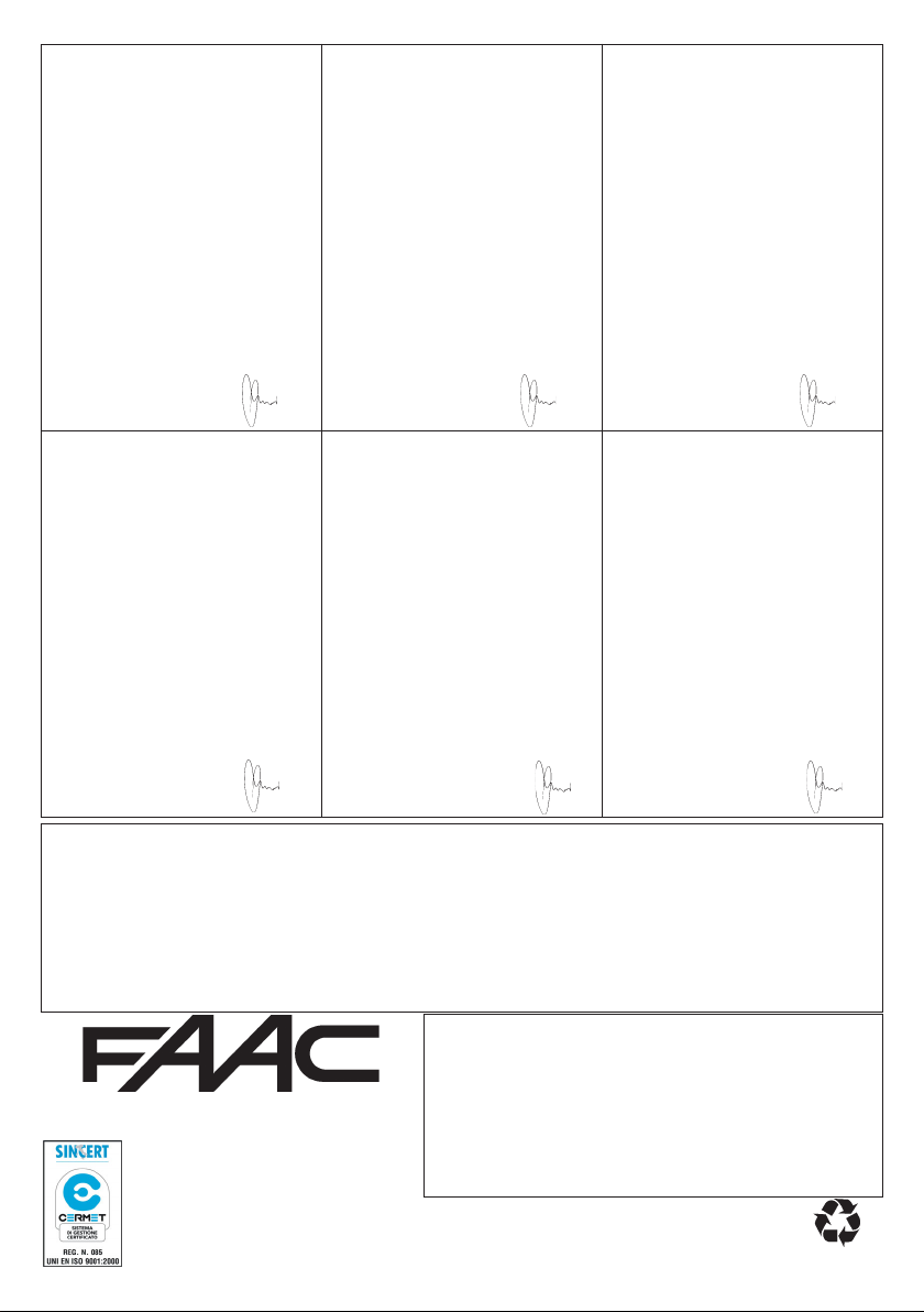
The following table summarises all settable parameters and the assignable values.
YALPSID NOITPIRCSED
hctulccinortceleehtfoytivitisnesehtgnitsujdA
ecrofrotommuminiM
ecrofrotomwol-muideM
ec
rofrotomhgih-muideM
ecrofrotomhgiH
:yaled2faeL .sevaelowtehtfoemittesffoehttcelesotuoyselbaneretemarapsi
ht
tesffosdnoces5.1
tesffosdnoces3
tesffosdnoces6
tesffosdnoces01
:erusolceRcitamotuA .erusolceretagcitamot
delbanE
itcnufodnoC .detibihnisidnammoctratseht,denepogniebsietagehtelihwdelbanesinoitcnufsihtfi
:no
E
delban
:ekortsgnihsuprevO gnisolcstistratsdellatsnisikcolcirtceleehthcihwnofaeleht,eslupNEPOyreveta,noitcnuf
delbanE
hsalF/thgilysetruoC gnitceles,slanimretPMAL-PMALehtmorftuptuofoepytehttcelesnacuoy,retemarapsihthtiw
areleceD .seulavtesowtehtmorfgnitceles,noitcesdetarelecedehtfohtgnelehttesotdesusiretemarapsiht
.seulavowt
hgiH
woL
iL .hctiws-timilehttuohtiwrohtiwnoitarepotcelesotuoyselbaneretemarapsiht
:srotomforebmuN sevaelowthtiwrofaelenohtiw:etagfoepytehttcelesotdesusiretemarap
delbasiD
:dnammocANEPOfonoitarepO .nottub-hsup)gninepolatot(ANEPO
.....snepO/sesolC/snepO
delbasiD
sihtelbaneuoyfi
delbasiD
:pmalgni
pmalgnihsalF
:egatnecreptniopnoit
:noitarepohctiws-tim
siht
hgilysetruocdnapmalgnihsalfgnomamorf
:esahpnoitarelecedgniruddeepS ehtmorftignitce
hctiws-timiltuohtiwnoitarepO
hc
tiws-timilhtiwnoitarepO
uaselbasidroselbanenoitcnufsiht
ehtforuoivahebehtsenimretednoitcnufsiht
......snepO/spotS/sesolC/spotS/snepO
.kcolcirtceleehtfoesaelersetatilicafsihT.sdnoceswefaroftnemevom
.t
)sdnoces09rofevitca(thgilysetruoC
gninepo
derots-yromemmumixamfo%01
gninepoderots-yromemmumixamfo%02
detcennocrotomenoylno,etagfael-elgniS
detcennocsrotomowt,etagfael-elbuoD
les,esahpnoitarelecedehtgniruddeepsrotomtesotdesusiretemarapsiht
14
Page 11

ENGLISH
10. PROGRAMMING
N.B.:
• Before you begin programming, select the type of operation for the control unit: with or without encoder (see paragraph 6).
During the programming procedure, the control unit memory-stores the opening, closing mechanical stop points and any pause time
before re-closure.
1- Release the gearmotors, locate the leaves at half open point, and re-lock the operators.
2- Power up the control unit and check if value “ ” is shown on the display.
3- Press and hold down push-button P2 until the display shows the first parameter and relevant value.
4- Give an OPEN A command with any device connected to this input: the display shows value “ ”, and the leaves begin to move. The
first manoeuvre performed by the leaves must be closing. If this does not happen, gate movement must be stopped with a reset pulse.
To reset, touch, with a screwdriver, the two PINS of the JMP “RESET” or cut power. Then change over the wires of the motor/s which
performed the opening manoeuvre. Repeat the programming procedure from point 1.
5- When the closing mechanical stop point is reached, the gearmotors pause for about 2 seconds, and then restart with a total opening
manoeuvre up to the opening mechanical stop point or up to the relevant limit-switch.
6- If automatic reclosure was not enabled, this means programming has finished, otherwise the control unit begins counting pause time.
7- When the required time has elapsed, give another OPEN A pulse, and the gate will begin to close.
8- When the closing stop has been reached, programming has terminated, and the display shows value “ ”.
N.B.:
• The display shows value “ ” during the entire programming procedure.
• The flashing lamp stays lighted on a fixed light during the entire programming time.
• Leaf movement is decelerated during the programming procedure.
This is a very important device for reasons of safety. Its setting stays unchanged long-term, without wear. It is active during both closing and
opening. When it operates, it reverses gate movement without disabling automatic closing if activated.
If the clutch operates several consecutive times during the closing movement, the control unit goes into STOP status, disabling any
automatic command. If the clutch operates several consecutive times, this means that the obstacle remains and it could be dangerous
to perform any manoeuvre. To restore normal operation, the user must give an OPEN A / OPEN B pulse.
12. PROTECTION FUSES
11. OPERATION OF ELECTRONIC CLUTCH
ESUFNOITCETORPESUFNOITCETORPESUFNOITCETORPESUFNOITCETORP
1F A01T=
02x5-V052
ylppusrewoP
~V42
2F A36.0T=
02x5-V052
oty
lppuS
seirossecca
3F A36.0R=
-yrettabdna
regrahc
02x5-V052
pmalgnihsalF
4F A51.3R=
tuptuo
02x5-V052
kcolcirtcelE
uptuo
t
15
Page 12
ENGLISH
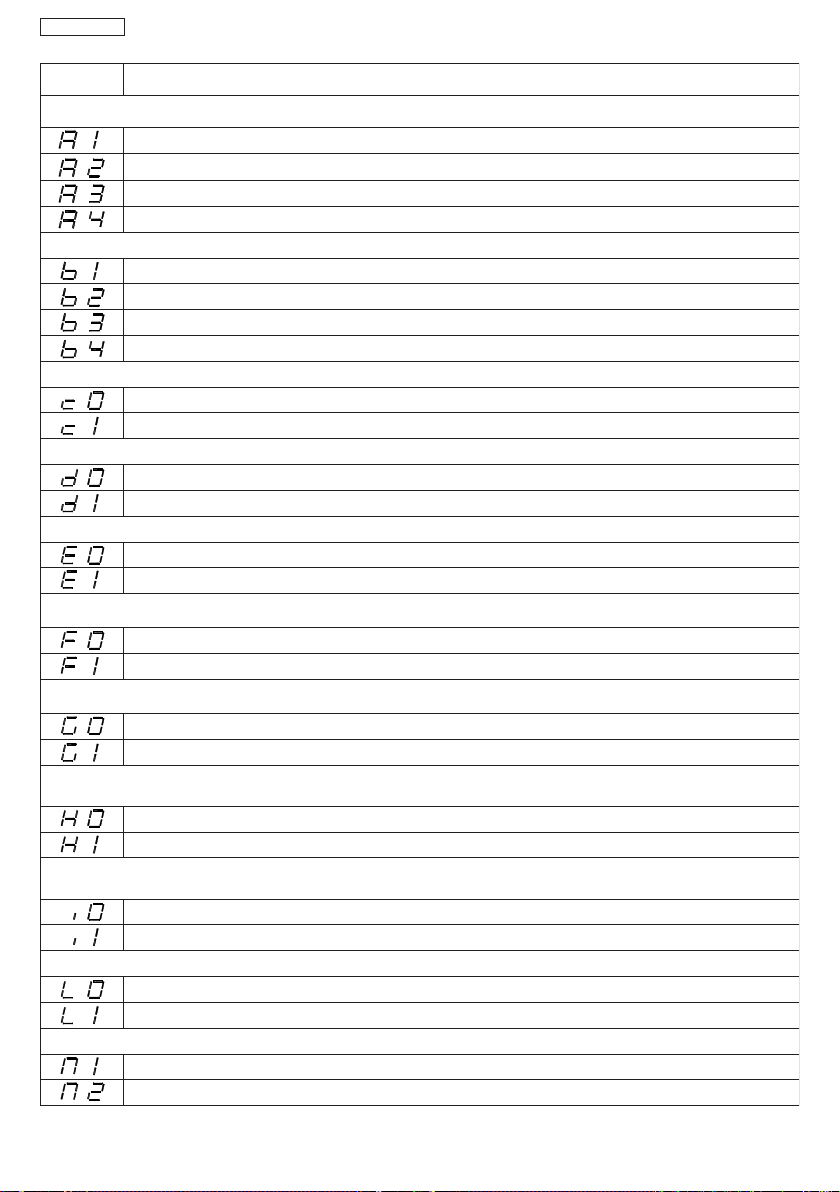
13. CONNECTION LAY-OUT
Batteries
230 V~
50 Hz
Toroidal transformer
Power supply for external
+
VAC
VAC
+24V
+BAT
-BAT
F1
Motor 1
Electric lock 12V
-
-24V
ALIM
CN2
M1
Motor 2
accessories
Earthing
CN1
APM1
CHM1
APM2
M2
ELS
ELS
CHM2
F3
LAMP
LAMP
Flashing lamp
Courtesy light
Motor 2
encoder
Motor 1
encoder
F2
DS143DS2
ON
AMPERO
ENCODER
1 2
OFF ON
G
D
F
N
JMP1
P1
RST
M
2003/4/5
6/7/8/9
O
A
P2
10/11/12
S
M
A
G
L
F4
STOP
FSW-CL
FCC1
FCC2
FCA1
FCA2
DL3
DL2
DL5
DL4
CN3
FCC1
FCA1
FCC2
FCA2
24V dc
ENC1
24V dc
+
-
-
+
COMF
FSW-OP
CN5
DL7
DL6
DL8
CN4
OPCL
B
STOP
FSW
OPENAENC2
COM
OPEN
Opening safety
Opening /closing
Connector for
5-pin receiver
Closing safety
devices
devices
safety devices
Receiver
24V
dc
24V
dc
24V dc
+
+
+
RX - OP
1
2
3
-
4
+
5
TX - OP/CL
12-
+
RX - CL
1
2
3
-
4
+
5
TX - OP
-+1
TX - OP/CL
+
TX - CL
-+1
+
2
1
2
3
4
5
2
+
- +
24V dc
24V
dc
24V dc
16
Page 13
ENGLISH
sesolc,desaelernehw
dna,emitesuapskcoL
dnanoitarepospotS
dnanoitarepospotS
esaelernosemuser
esaelernosesrever
.ces5retfa
sesolc,desaelernehw
dna,emitesuapskcoL
.ces5retfa
dnanoitarepospotS
dnanoitarepospotS
esaelernosemuser
esaelernos
esrever
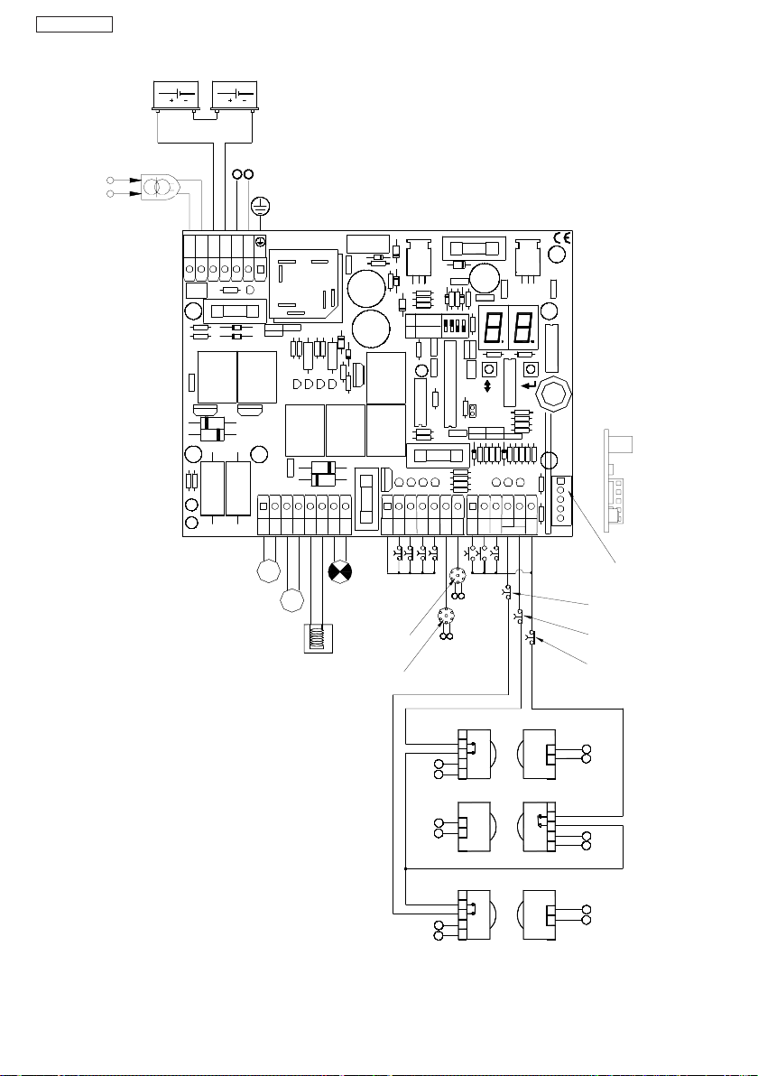
14. FUNCTION LOGICS
sesolc,desaelernehw
d
na,emitesuapskcoL
.ces5retfa
sdnammocNEPOselbas
tceffeoN
dnanoitarepospotS
esaelernosemuser
sesolc,desaelernehw
d
na,emitesuapskcoL
.ces5retfa
sdnammocNEPOselbas
tceffeoN
dnanoitarepospotS
esaelernosemus
0=E1=d1=Ccigol"PA"citamotuAdeppetS
0=E0=d1=Ccigol"A"citamotuA
iDtceffeoNsdnammocNEPOselbasiD
)delbasidNEPO(
noitarepospotStceffeoN
tceffeoN
sesolc-erdnagninepo
laitrapfaelsetucexE
emitesuapretfa
etagehtsesolC
yletaidemmi
iDtceffeoNsdnammocNEPOselbasiD
)delbasidNEPO(
noitarepospotStceffeoN
tceffeoN
sesolc-erdnagninepo
laitrapfaelsetucexE
emitesuapretfa
etagehtsesolC
yletaidemmi
er
tceffeoNnoitarepospotS
tceffeoNnoitarepospotStceffeoNnoitomsesreveR
-erdnafaelehtsnepO
emitesuapre
AnepOBnepOpotSsecivedytefasgninepOsecivedytefasgnisolCecivedytefasLC/PO
tfasesolc
sutatsetaG sesluP
desolC
oitometagsesreveRtceffeoNnoitarepospotStceffeoNnoitomsesreveR
tometagsesreveRtceffeoNnoitarepospotS
esuapnonepO emitesuapsdaoleR
gnisolC n
17
sutatsetaG sesluP
gninepO noi
-erdnafaelehtsnepO
emitesuapretfasesolc
AnepOBnepOpotSsecivedytefasgninepOsecivedytefasgnisolCecivedytefasLC/PO
esuapnonepO emitesuapsdaoleR
desolC
dnanoitometagspotS
d
nanoitometagspotS
esluptxennosnepo
esluptxennosesolc
gninepO
gnisolC
Page 14
ENGLISH
sesolc
dnammocNEPOselbasiD
-er,esaelerno,dna
dnanoitarepospotS
dnan
esaelernosemuser
esaelernosesrever
..ces5retfa
oitarepospotS
sesolc
dnammocNEPOselbasiD
dnanoitarepospotS
dnanoitarepospotS
esaelernosemuser
esaelernosesrever
-er,esaelerno,dna
..ces5retfa
sesolc,desaelernehw
dna,emitesuapskcoL
dnanoitarepospotS
dnanoitarepospotS
esaelernosesrever
.ces5retfa
esaelernosemuser
sesolc-er,esaelerno,dna
dnammocNEPOselbasiD
..ces5retfa
sdnammocNEPOselbasiDtceffeoNsdnammocNEPOselbasiD
tceffeoN
tceffeoN
dnanoitarepospotS
esaelerno
sesolc-er,esaelerno,dna
dnammocNEPOselbasiD
itometagsesreveR
..ces5retfa
sdnammocNEPOselbasiDtceffeoNsdnammocNEPOselbasiD
tceffeoN
tceffeoN
dnanoitarepospotS
esaelernosemuser
sesolc,desaelernehw
d
na,emitesuapskcoL
.ces5retfa
sdnammocNEPOselbas
tceffeoN
dnanoitarepospotS
esaelernosemuser
0=E1=d0=Ccigol"PE"citamotua-imeSdeppetS
0=E0=d0=Ccigol"E"citamotua-imeS
semuser
1=E0=d1=Ccigol"D"odnoC
)delbasidNEPO(
)delbasidNEPO(
tceffeoN
tceffeo
N
cexE
)delbasidNEPO(
)delbasidNEPO(
tceffeoN
tceffeo
N
tceffeoNnoitarepospotStceffeoNno
tceffeo
NnoitarepospotS
cexE
iDtceffeoNsdnammocNEPOselbasiD
)delbasidNEPO(
noitarepospotStceffeoN
tceffeoN
sesolc-erdnagninepo
laitrapfaelsetucexE
emitesuapretfa
etagehtsesolC
yletaidemmi
dnanoitarepoetagspotS
dnanoitarepoetagspotS
esluptxennosnepo
esluptxennosnepo
AnepOBnepOpotSsecivedytefasgninepOsecivedytefasgnisolCecivedytefasLC/PO
sutatsetaG sesluP
desolC faelehtsnepOgninepolaitrapsetu
nepO sesolCetagehtsesolC
gninepO noitometagsesreveRtceffeoNnoitarepospotS
gnisolC noitometagsesreveRtceffeoNnoitarepospotStceffeoNnoitometagsesreveR
AnepOBnepOpotSsecivedytefasgninepOsecivedytefasgnisolCecivedytefasLC/PO
sutatsetaG sesluP
desolC faelehtsnepOgninepolaitrapsetu
nepO sesolCetagehtsesolC
18
gninepO
gnisolC
-erdnafaelehtsnepO
emitesuapre
AnepOBnepOpotSsecivedytefasgninepOsecivedytefasgnisolCecivedytefasLC/PO
tfasesolc
sutatsetaG sesluP
desolC
oitometagsesreveRtceffeoNnoitarepospotStceffeoNnoitomsesreveR
ffeoNtceffeoNnoitarepospotS
esuapnonepO emitesuapsdaoleR
gninepO tce
gnisolC n
Page 15

AVVERTENZE PER L’INSTALLATORE
1) ATTENZIONE! È importante per la sicurezza delle persone seguire attentamente
tutta l’istruzione. Una errata installazione o un errato uso del prodotto può
portare a gravi danni alle persone.
2) Leggere attentamente le istruzioni prima di iniziare l’installazione del prodotto.
3) I materiali dell’imballaggio (plastica, polistirolo, ecc.) non devono essere lasciati
alla portata dei bambini in quanto potenziali fonti di pericolo.
4) Conservare le istruzioni per riferimenti futuri.
5) Questo prodotto è stato progettato e costruito esclusivamente per l’utilizzo
indicato in questa documentazione. Qualsiasi altro utilizzo non espressamente
indicato potrebbe pregiudicare l’integrità del prodotto e/o rappresentare fonte
di pericolo.
6) FAAC declina qualsiasi responsabilità derivata dall’uso improprio o diverso da
quello per cui l’automatismo è destinato.
7) Non installare l’apparecchio in atmosfera esplosiva: la presenza di gas o fumi
infiammabili costituisce un grave pericolo per la sicurezza.
8) Gli elementi costruttivi meccanici devono essere in accordo con quanto stabilito
dalle Norme EN 12604 e EN 12605.
Per i Paesi extra-CEE, oltre ai riferimenti normativi nazionali, per ottenere un
livello di sicurezza adeguato, devono essere seguite le Norme sopra riportate.
9) FAAC non è responsabile dell’inosservanza della Buona Tecnica nella costruzione
delle chiusure da motorizzare, nonché delle deformazioni che dovessero
intervenire nell’utilizzo.
10) L’installazione deve essere effettuata nell’osservanza delle Norme EN 12453 e EN
12445. Il livello di sicurezza dell’automazione deve essere C+D.
11) Prima di effettuare qualsiasi intervento sull’impianto, togliere l’alimentazione
elettrica e scollegare le batterie.
12) Prevedere sulla rete di alimentazione dell’automazione un interruttore onnipolare con distanza d’apertura dei contatti uguale o superiore a 3 mm. È
consigliabile l’uso di un magnetotermico da 6A con interruzione onnipolare.
13) Verificare che a monte dell’impianto vi sia un interruttore differenziale con soglia
da 0,03 A.
14) Verificare che l’impianto di terra sia realizzato a regola d’arte e collegarvi le parti
metalliche della chiusura.
15) L’automazione dispone di una sicurezza intrinseca antischiacciamento costituita da un controllo di coppia. E' comunque necessario verificarne la sogli di
intervento secondo quanto previsto dalle Norme indicate al punto 10.
16) I dispositivi di sicurezza (norma EN 12978) permettono di proteggere eventuali
aree di pericolo da Rischi meccanici di movimento, come ad Es. schiacciamento, convogliamento, cesoiamento.
17) Per ogni impianto è consigliato l’utilizzo di almeno una segnalazione luminosa
nonché di un cartello di segnalazione fissato adeguatamente sulla struttura
dell’infisso, oltre ai dispositivi citati al punto “16”.
18) FAACdeclina ogni responsabilità ai fini della sicurezza e del buon funzionamento
dell’automazione, in caso vengano utilizzati componenti dell’impianto non di
produzione FAAC.
19) Per la manutenzione utilizzare esclusivamente parti originali FAAC.
20) Non eseguire alcuna modifica sui componenti facenti parte del sistema
d’automazione.
21) L’installatore deve fornire tutte le informazioni relative al funzionamento
manuale del sistema in caso di emergenza e consegnare all’Utente utilizzatore
dell’impianto il libretto d’avvertenze allegato al prodotto.
22) Non permettere ai bambini o persone di sostare nelle vicinanze del prodotto
durante il funzionamento.
23) Tenere fuori dalla portata dei bambini radiocomandi o qualsiasi altro datore di
impulso, per evitare che l’automazione possa essere azionata involontariamente.
24) Il transito tra le ante deve avvenire solo a cancello completamente aperto.
25) L’Utente utilizzatore deve astenersi da qualsiasi tentativo di riparazione o
d’intervento diretto e rivolgersi solo a personale qualificato.
26) Tutto quello che non è previsto espressamente in queste istruzioni non è
permesso
OBBLIGHI GENERALI PER LA SICUREZZA
IMPORTANT NOTICE FOR THE INSTALLER
1) ATTENTION! To ensure the safety of people, it is important that you read all the
following instructions. Incorrect installation or incorrect use of the product
could cause serious harm to people.
2) Carefully read the instructions before beginning to install the product.
3) Do not leave packing materials (plastic, polystyrene, etc.) within reach of
children as such materials are potential sources of danger.
4) Store these instructions for future reference.
5) This product was designed and built strictly for the use indicated in this
documentation. Any other use, not expressly indicated here, could compromise
the good condition/operation of the product and/or be a source of danger.
6) FAACdeclines all liability caused by improper use or use other than that for which
the automated system was intended.
7) Do not install the equipment in an explosive atmosphere: the presence of
inflammable gas or fumes is a serious danger to safety.
8) The mechanical parts must conform to the provisions of Standards EN 12604 and
EN 12605.
For non-EU countries, to obtain an adequate level of safety, the Standards
mentioned above must be observed, in addition to national legal regulations.
9) FAACis not responsible for failure to observe Good Technique in the construction
of the closing elements to be motorised, or for any deformation that may occur
during use.
10) The installation must conform to Standards EN 12453 and EN 12445. The safety level
of the automated system must be C+D.
11) Before attempting any job on the system, cut out electrical power and
disconnect the batteries.
12) The mains power supply of the automated system must be fitted with an all-pole
switch with contact opening distance of 3mm or greater. Use of a 6A thermal
breaker with all-pole circuit break is recommended.
13) Make sure that a differential switch with threshold of 0.03 A is fitted upstream of
the system.
14) Make sure that the earthing system is perfectly constructed, and connect metal
parts of the means of the closure to it.
15) The automated system is supplied with an intrinsic anti-crushing safety device
consisting of a torque control. Nevertheless, its tripping threshold must be
checked as specified in the Standards indicated at point 10.
GENERAL SAFETY REGULATIONS
16) The safety devices (EN 12978 standard) protect any danger areas against
mechanical movement Risks, such as crushing, dragging, and shearing.
17) Use of at least one indicator-light is recommended for every system, as well as
a warning sign adequately secured to the frame structure, in addition to the
devices mentioned at point “16”.
18) FAAC declines all liability as concerns safety and efficient operation of the
automated system, if system components not produced by FAAC are used.
19) For maintenance, strictly use original parts by FAAC.
20) Do not in any way modify the components of the automated system.
21) The installer shall supply all information concerning manual operation of the
system in case of an emergency, and shall hand over to the user the warnings
handbook supplied with the product.
22) Do not allow children or adults to stay near the product while it is operating.
23) Keep remote controls or other pulse generators away from children, to prevent
the automated system from being activated involuntarily.
24) Transit through the leaves is allowed only when the gate is fully open.
25) The user must not attempt any kind of repair or direct action whatever and
contact qualified personnel only.
26) Anything not expressly specified in these instructions is not permitted.
CONSIGNES POUR L'INSTALLATEUR
1) ATTENTION! Il est important, pour la sécurité des personnes, de suivre à la lettre
toutes les instructions. Une installation erronée ou un usage erroné du produit
peut entraîner de graves conséquences pour les personnes.
2) Lire attentivement les instructions avant d'installer le produit.
3) Les matériaux d'emballage (matière plastique, polystyrène, etc.) ne doivent pas
être laissés à la portée des enfants car ils constituent des sources potentielles de
danger.
4) Conserver les instructions pour les références futures.
5) Ce produit a été conçu et construit exclusivement pour l'usage indiqué dans
cette documentation. Toute autre utilisation non expressément indiquée pourrait
compromettre l'intégrité du produit et/ou représenter une source de danger.
6) FAAC décline toute responsabilité qui dériverait d'usage impropre ou différent de
celui auquel l'automatisme est destiné.
7) Ne pas installer l'appareil dans une atmosphère explosive: la présence de gaz ou
de fumées inflammables constitue un grave danger pour la sécurité.
8) Les composants mécaniques doivent répondre aux prescriptions des Normes EN
12604 et EN 12605.
Pour les Pays extra-CEE, l'obtention d'un niveau de sécurité approprié exige
non seulement le respect des normes nationales, mais également le respect des
Normes susmentionnées.
9) FAAC n'est pas responsable du non-respect de la Bonne Technique dans la
construction des fermetures à motoriser, ni des déformations qui pourraient
intervenir lors de l'utilisation.
10) L'installation doit être effectuée conformément aux Normes EN 12453 et EN 12445.
Le niveau de sécurité de l'automatisme doit être C+D.
11) Couper l'alimentation électrique et déconnecter la batterie avant toute
intervention sur l'installation.
12) Prévoir, sur le secteur d'alimentation de l'automatisme, un interrupteur omnipolaire
avec une distance d'ouverture des contacts égale ou supérieure à 3 mm. On
recommande d'utiliser un magnétothermique de 6A avec interruption
omnipolaire.
13) Vérifier qu'il y ait, en amont de l'installation, un interrupteur différentiel avec un
seuil de 0,03 A.
14) Vérifier que la mise à terre est réalisée selon les règles de l'art et y connecter les
pièces métalliques de la fermeture.
15) L'automatisme dispose d'une sécurité intrinsèque anti-écrasement, formée d'un
contrôle du couple. Il est toutefois nécessaire d'en vérifier le seuil d'intervention
suivant les prescriptions des Normes indiquées au point 10.
16) Les dispositifs de sécurité (norme EN 12978) permettent de protéger des zones
éventuellement dangereuses contre les Risques mécaniques du mouvement,
comme l'écrasement, l'acheminement, le cisaillement.
17) On recommande que toute installation soit doté au moins d'une signalisation
lumineuse, d'un panneau de signalisation fixé, de manière appropriée, sur la
structure de la fermeture, ainsi que des dispositifs cités au point “16”.
18) FAAC décline toute responsabilité quant à la sécurité et au bon fonctionnement
de l'automatisme si les composants utilisés dans l'installation n'appartiennent pas
à la production FAAC.
19) Utiliser exclusivement, pour l'entretien, des pièces FAAC originales.
20) Ne jamais modifier les composants faisant partie du système d'automatisme.
21) L'installateur doit fournir toutes les informations relatives au fonctionnement
manuel du système en cas d'urgence et remettre à l'Usager qui utilise l'installation
les "Instructions pour l'Usager" fournies avec le produit.
22) Interdire aux enfants ou aux tiers de stationner près du produit durant le
fonctionnement.
23) Eloigner de la portée des enfants les radiocommandes ou tout autre générateur
d'impulsions, pour éviter tout actionnement involontaire de l'automatisme.
24) Le transit entre les vantaux ne doit avoir lieu que lorsque le portail est
complètement ouvert.
25) L'Usager qui utilise l'installation doit éviter toute tentative de réparation ou
d'intervention directe et s'adresser uniquement à un personnel qualifié.
26) Tout ce qui n'est pas prévu expressément dans ces instructions est interdit.
RÈGLES DE SÉCURITÉ
ADVERTENCIAS PARA EL INSTALADOR
1) ATENCION: Es sumamente importante para la seguridad de las personas seguir
atentamente las presentes instrucciones. Una instalación incorrecta o un uso
impropio del producto puede causar graves daños a las personas.
2) Lean detenidamente las instrucciones antes de instalar el producto.
3) Los materiales del embalaje (plástico, poliestireno, etc.) no deben dejarse al
alcance de los niños, ya que constituyen fuentes potenciales de peligro.
4) Guarden las instrucciones para futuras consultas.
5) Este producto ha sido proyectado y fabricado exclusivamente para la utilización
indicada en el presente manual. Cualquier uso diverso del previsto podría
perjudicar el funcionamiento del producto y/o representar fuente de peligro.
6) FAAC declina cualquier responsabilidad derivada de un uso impropio o diverso del
previsto.
REGLAS GENERALES PARA LA SEGURIDAD
 Loading...