

Page 1
Contents
EC DECLARATION OF CONFORMITY FOR MACHINES .................................................................................... p. 11
WARNINGS FOR THE INSTALLER ....................................................................................................................... p. 11
1. DESCRIPTION AND TECHNICAL SPECIFICATIONS .................................................................................... p. 12
1.1. DIMENSIONS ................................................................................................................................ p. 12
2. ELECTRIC DEVICES (standard system) .................................................................................................... p. 12
3. INSTALLING THE AUTOMATED SYSTEM ...................................................................................................... p. 13
3.1. PRELIMINARY CHECKS ................................................................................................................ p. 13
3.2. INSTALLATION DIMENSIONS ........................................................................................................ p. 13
3.2.1. GENERAL RULES FOR DETERMINING THE INSTALLATION DIMENSIONS ............................ p. 13
3.3. INSTALLATION OF THE OPERATORS ............................................................................................. p. 13
4. START-UP .................................................................................................................................................... p. 15
4.1. ADJUSTING THE ANTI-CRUSHING SYSTEM .................................................................................. p. 15
5. FINAL OPERATIONS ................................................................................................................................... p. 16
6. AUTOMATED SYSTEM TEST ......................................................................................................................... p. 16
7. MANUAL OPERATION ............................................................................................................................... p. 16
8. RESTORING NORMAL OPERATION MODE ................................................................................................ p. 17
9. SPECIAL APPLICATIONS FOR SWING LEAF GATES ................................................................................... p. 17
9.1. OPENING TOWARD THE OUTSIDE, WITH OPERATOR INSTALLED INSIDE ..................................... p. 17
10. MAINTENANCE .......................................................................................................................................... p. 17
11. REPAIRS ..................................................................................................................................................... p. 17
12. TROUBLE SHOOTING ................................................................................................................................. p. 18
Read this instruction manual to the letter before you begin to install the product.
Symbol highlights notes that are important for people’s safety and for the good condition of the automated system.
Symbol draws your attention to the notes about the product’s characteristics or operation.
FAAC S.p.A.
Via Benini, 1
40069 Zola Predosa (BO) - ITALIA
Tel.: 051/61724 - Fax: 051/758518
www.faac.it
10
732870 Rev. A
Page 2
EC DECLARATION OF CONFORMITY FOR MACHINES
(DIRECTIVE 98/37/EC)
Manufacturer: FAAC S.p.A.
Address: Via Benini, 1 - 40069 Zola Predosa BOLOGNA - ITALY
Declares that: 422 mod. operator,
• is built to be integrated into a machine or to be assembled with other machinery to create a machine under
the provisions of Directive 98/37/EC;
• conforms to the essential safety requirements of the following EEC directives:
73/23/EEC and subsequent amendment 93/68/EEC.
89/336/EEC and subsequent amendment 92/31/EEC and 93/68/EEC
and also declares that it is prohibited to put into service the machinery until the machine in which it will be
integrated or of which it will become a component has been identified and declared as conforming to the
conditions of Directive 98/37/EC.
Bologna, 01 January 2005
The Managing Director
A. Bassi
WARNINGS FOR THE INSTALLER
GENERAL SAFETY OBLIGATIONS
1) ATTENTION! To ensure the safety of people, it is important that you read
all the following instructions. Incorrect installation or incorrect use of
the product could cause serious harm to people.
2)
Carefully read the instructions before beginning to install the product.
3) Do not leave packing materials (plastic, polystyrene, etc.) within reach
of children as such materials are potential sources of danger.
4) Store these instructions for future reference.
5) This product was designed and built strictly for the use indicated in this
documentation. Any other use, not expressly indicated here, could
compromise the good condition/operation of the product and/or be a
source of danger.
6) FAAC declines all liability caused by improper use or use other than that
for which the automated system was intended.
7) Do not install the equipment in an explosive atmosphere: the presence
of inflammable gas or fumes is a serious danger to safety.
8) The mechanical parts must conform to the provisions of Standards EN
12604 and EN 12605.
For non-EU countries, to obtain an adequate level of safety, the Standards
mentioned above must be observed, in addition to national legal
regulations.
9) FAAC is not responsible for failure to observe Good Technique in the
construction of the closing elements to be motorised, or for any
deformation that may occur during use.
10) The installation must conform to Standards EN 12453 and EN 12445.
For non-EU countries, to obtain an adequate level of safety, the Standards
mentioned above must be observed, in addition to national legal
regulations.
11) Before attempting any job on the system, cut out electrical power .
12) The mains power supply of the automated system must be fitted with an
all-pole switch with contact opening distance of 3mm or greater. Use of
a 6A thermal breaker with all-pole circuit break is recommended.
13) Make sure that a differential switch with threshold of 0.03 A is fitted
upstream of the system.
14) Make sure that the earthing system is perfectly constructed, and
connect metal parts of the means of the closure to it.
15) The safety devices (EN 12978 standard) protect any danger areas
against mechanical movement Risks, such as crushing, dragging,
and shearing.
16) Use of at least one indicator-light (e.g. FAACLIGHT ) is recommended
for every system, as well as a warning sign adequately secured to the
frame structure, in addition to the devices mentioned at point “15”.
17) FAAC declines all liability as concerns safety and efficient operation
of the automated system, if system components not produced by
FAAC are used.
18) For maintenance, strictly use original parts by FAAC.
19) Do not in any way modify the components of the automated system.
20) The installer shall supply all information concerning manual operation
of the system in case of an emergency, and shall hand over to the user
the warnings handbook supplied with the product.
21) Do not allow children or adults to stay near the product while it is
operating.
22) Keep remote controls or other pulse generators away from children,
to prevent the automated system from being activated involuntarily.
23) Transit through the leaves is allowed only when the gate is fully open.
24) The user must not attempt any kind of repair or direct action whatever
and contact qualified personnel only.
25) Maintenance: check at least every 6 months the efficiency of the
system, particularly the efficiency of the safety devices (including,
where foreseen, the operator thrust force) and of the release devices.
26) Anything not expressly specified in these instructions is not permitted.
11
Page 3
422 AUTOMATION SYSTEM
These instructions apply to the following models:
422 CBCS - 422 CBACS - 422 SBS - 422 CBC - 422 CBAC 422 SB - 422 CBC PED. - 422 SB PED.
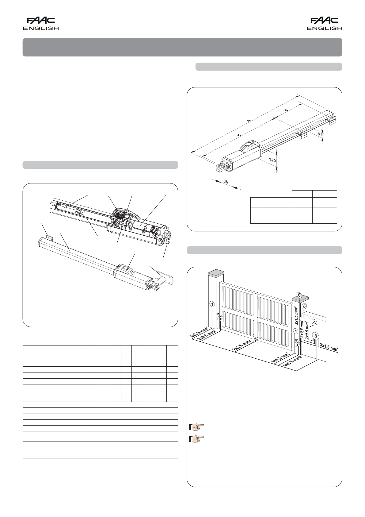
1.1. DIMENSIONS
The FAAC 422 automated system for swing leaf gates consists of
an enbloc composed of an electric pump and a hydraulic piston
which transmits drive to the leaf.
The models with a hydraulic locking do not require installation of
electric locks, as they guarantee mechanical locking of the leaf
when the motor is not operating.
The models without a hydraulic locking, require the installation of
electric locks to ensure the leaf is mechanically locked.
The 422 automated systems were designed and built to automate
swing leaf gates. Do not use for any other purpose.
1. DESCRIPTION AND TECHNICAL SPECIFICATIONS
Fig. 2
A
B
C
LLAREVO
SNOISNEMID
NEEWTEBECNATSID
STNEMHCATTA
EKORTSEVITCEFFE.mm042.mm061
2. ELECTRIC DEVICES (standard system)
EPYTROTAREPO
DRADNATSNAIRTSEDEP
.mm789.mm728
.mm396.mm316
Electric motor
Release lock
Hydraulic piston
Cylinder
By-pass valves
Gerotor pump
Electrical cable bend
guard
Front attachment
Housing
Emergency release
Rear attachment
Fig. 1
Tab. 1: Technical specifications of “422 Operator”
LEDOMSCBCSCABCSBSCBCCABCBS
ecroftsurht/noitcarT
)Nad(xam
gnikcolciluardyH
)gK(thgiewrotarepO
ylppusrewoP
)W(rewopdebrosbA
)A(tnerrucdebrosbA
)mpr(rotomcirtcelE
noitcetorplamrehT
gnidniwno
roticapactsurhT
tneibmagnitarepO
erutarepmet
ssalcnoitcetorP
096096096005005005083083
042042042042042042061061
)mm(ekortsevitceffedoR
1113,13,13,122
)s/mc(deepsraenildoR
5555555555550707
)ruoh/selcyc(ycneuqerfesU
57,057,057,01115,15,1
)nim/l(etar-wolfpmuP
)1()2(/)1()2(/)1(/
08,108,1308,108,13)3()3(
)m(htgnelmumixamfaeL
7
022
1
selop4-0041
C°021
.V004/Fu8
C°55+C°04-
55PI
CBC
.zH05/)%01-%6+(caV032
Fig. 3
.DEP
.DEP
BS
Operators mod. 400
(provide a connector block for each operator)
Photocells
Electronic control unit
Key operated push-button T 10
Radio receiver
Flashing light
Electric lock (if necessary)
1) To lay the electrical cables, use adequate rigid
and/or flexible pipes.
2) Always separate the connection cables of the
low voltage accessories from the 230 V power
cables. Use separate sheaths to avoid any type
of interference.
(1) Closing - (2) Opening and closing
(3) Max. 1,20 m. - Min. 0,80 m.
12
Page 4
3. INSTALLING THE AUTOMATED SYSTEM
pedestrian operators
3.1. PRELIMINARY CHECKS
To ensure a correctly operating automated system, the structure
of the existing gate or gate to be built must satisfy the following
requirements:
• Max length of leaves according to the dimensions of Table 1.
• A strong and rigid leaf structure.
• Smooth, uniform leaves movement, without any irregular friction
during the entire travel;
• Existing hinges in good condition.
• Travel limit mechanical stops must be provided.
We advise you to carry out the metalwork jobs before installing
the automated system.
The condition of the structure directly influences the reliability and
safety of the automated system.
3.2. INSTALLATION DIMENSIONS
3.2.1. GENERAL RULES FOR DETERMINING THE
INSTALLATION DIMENSIONS
If the dimensions indicated in table A or B cannot be executed,
the following must be considered in order to determine different
measurements:
- to obtain 90° opening of the leaf: a + b = c.
- to obtain over 90° opening of the leaf: a + b < c.
- lower a and b dimensions will result in higher speeds. We advise
you to observe the current legal regulations;
- limit the difference of the a and b dimensions to within 40 mm:
higher differences will considerably vary speed during the
opening and closing motion;
- for reasons of operator dimensions, the minimum Z dimension
is 50 mm (Fig. 4);
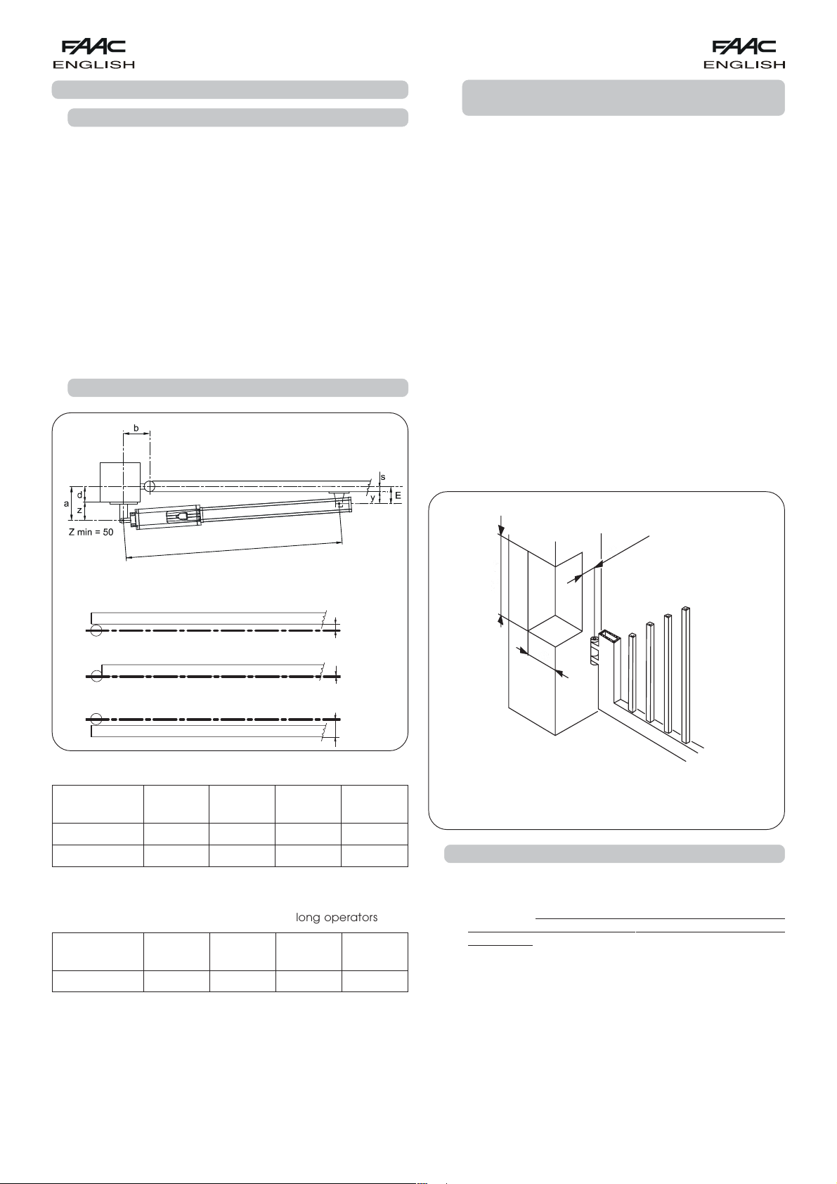
- if the pilaster dimensions or the position of the hinge (dimension
d) do not make it possible to contain dimension a to the
required size, a niche must be made in the pilaster as shown
in Fig. 5;
Fig. 4
dimensions in mm
Lo
Standard=933 mm. - pedestrian=773 mm.
Table A: Recommended dimensions for standard operators
gninepO
elgna
°09
°011
(*) Rod effective stroke (**) maximum dimension
Table B: Recommended dimensions for long operators
gninepO
elgna
°09
(*) Rod effective stroke (**) maximum dimension
c = The effective rod stroke is shorter than the maximum stroke,
in order to prevent the rod from reaching its stop point
internally, during the opening and closing stages.
a
)mm(
b
)mm(
02102104207
00100104205
a
)mm(
b
)mm(
080806103
)*(c
)mm(
)*(c
)mm(
y=65mm.
S < 0
S = 0
S > 0
)**(d
)mm(
)**(d
)mm(
- dimension a must always be larger than dimension E.
For installations opening toward the outside, refer to paragraph
9.1.
(1) Length of dimension “a” - 50 mm.
(2) Length of dimension “b” + 50 mm.
Fig. 5
3.3. INSTALLATION OF THE OPERATORS
1) Fasten the rear attachment on the pilaster, following the
indications in Tables A/B. Modify, if necessary, the length of
the supplied attachment.
Attention: To avoid compromising good operator
functionality, we recommend you to respect the indicated
dimensions.
• For iron pilasters, accurately weld the rear attachment
(ref., Fig. 6) directly on the pilaster.
• For masonry pilasters, select one of the following solutions:
A) appropriately lay a walling-in plate and then
accurately weld the rear attachment.
B) secure, with screws and expansion plugs, the rear
attachment plate (ref. a, Fig.6) to the pilaster and
then accurately weld the rear attachment to the
plate as shown in Fig. 6.
13
Page 5

2) Secure the operator to the rear attachment with the
supplied screws (Fig. 6).
3) Screw, halfway down, the front attachment onto the rod
(ref. Fig.8) and tighten with the supplied nut.
4) Release the operator (see chapter 7).
Fig. 8
5) Fully remove the rod to its stop point and make it recede
by about 5 mm (Fig.7).
Fig. 6
Fig. 7
attachment to prevent welding waste from damaging it
(Fig.10).
Notes:
A) We advise you to grease all the securing pins of
the attachments.
B) If welding is impossible, the plates of the front and
rear attachments are designed to be secured with
screws if necessary.
6) Relock the operator (see chapter 8).
7) Fit the front attachment onto the rod (ref. Fig. 8)
8) Close the gate leaf and, keeping the operator perfectly
horizontal, find the position of the front attachment (Fig. 9)
on the leaf.
9) Provisionally fix the front attachment on the leaf with two
weld spots, protecting the rod against any welding waste.
NB.:
If the gate structure does not permit the attachment to
be firmly fastened, take action on the structure, creating
a solid support base.
10) Release the operator and manually check if the gate is
free to open completely stopping on the travel limit
mechanical stops and if leaf movement is good and
friction- free.
Fig. 9
Fig. 10
11) Definitively weld the front attachment on the leaf.
To do this, temporarily release the operator from the
14
Page 6

Fig. 11
12) Prepare the protective housing and fit it on the operator
as shown in Fig. 11.
A) Insert the two anti-vibration spacers onto the front
flange.
B) Introduce the housing, pressing it firmly on the rear cover
.
C) Secure the housing with the self-tapping screw .
D) Fit the front cover on the housing and fasten it with
FIX plug .
13) Fit the electric cable bend guard (ref., Fig. 14).
14) Re-lock the operator and make the electrical connections
of the selected electronic control unit following the relevant
instructions.
4. START-UP
4.1. ADJUSTING THE ANTI-CRUSHING SYSTEM
The 422 automated system has an anti-crushing safety device
which limits the operator's force if an obstacle is encountered
while the gate is moving. To adjust the intervention threshold of
the anti-crushing system, temporarily open the release unit.
- Lift the protective plug (Fig. 12, ref. ) and fit the supplied key
(Fig. 12, ref. ).
15
Fig. 12
Page 7

- Turn the key 90°clockwise to open the cover.
- Lift up the cover (Fig. 13).
- Back off the screw (Fig. 13, ref. ) which secures the knob, and
withdraw the knob (Fig. 13, ref. ).
- Turn the force adjustment screws (By-Pass) (Fig. 13, ref. and )
on the operator.
- OPEN screw (green wording) : gate opening direction.
- CLOSE screw (red wording) : gate closing direction.
- To reduce torque, turn the screws anti-clockwise.
- To increase torque, turn the screws clockwise.
- When you have finished adjusting, re-position the knob (Fig. 13,
ref. ) and fasten the screw (Fig. 13, ref. ).
- Close the cover and lock it by turning the key anti-clockwise.
To adjust the torque limiters, consult Standards EN 12453 and EN
12445 for EU member countries and current legal regulations in
the other countries.
5. FINAL OPERATIONS
Finish the installation operations as follows:
- Close the cover of the release device with the key.
- Remove the breather screw (Fig.14, ref. )
Fig. 14
6. AUTOMATED SYSTEM TEST
When you have finished installing, apply the danger signal sticker
on the side of the operator so that it is clearly visible (Fig.15).
Run an accurate functional check of the automated system and
of all the accessories connected to it, especially the safety devices.
Hand the “User’s Guide” to the Client, explain correct operation
and use of the operator, and indicate the potentially dangerous
areas of the automated system.
Fig. 13
Fig. 15
7. MANUAL OPERATION
If the gate has to be moved manually due to a power cut or fault
of the automated system, use the release device as follows:
- Lift the protective plug (Fig. 16, ref. ) and fit the supplied key
(Fig. 16, ref. ).
- Turn the key 90°clockwise to open the cover.
- Lift up the cover (Fig. 16 ref. ).
- Turn the release knob anti-clockwise for about two turns (Fig. 16,
ref. ).
- Open or close the leaf manually.
16
Page 8

8. RESTORING NORMAL OPERATION MODE
To prevent an involuntary pulse from activating the operator
during the manoeuvre, cut power to the system before re-locking
the operator.
- To re-lock the operator, turn the release knob clockwise until it
stops (Fig. 16, ref. 햵).
- Close the cover and turn the key 90° anti-clockwise (Fig. 16, ref. 햳).
- Finally, remove the key and close the protective plug
(Fig. 16, ref. 햲).
Table C: Recommended dimensions for standard operators
gninepO
elgna
°09
°09
°09
(*) Rod effective stroke (**) maximum dimension
a
00109005042
011001006042
021011007042
b
)mm(
s
)mm(
)mm(
)**(d
)mm(
)*(c
)mm(
햴
햳
UNLOCK
LOCK
햵
햲
Fig. 16
9. SPECIAL APPLICATIONS FOR SWING LEAF GATES
9.1. OPENING TOWARD THE OUTSIDE, WITH
OPERATOR INSTALLED INSIDE (Fig. 17)
For this special application, refer to Table 1, and select the STANDARD operator according to leaf length.
For leaves with a length of up to 1,8 m, we advise you to use the
CBAC STANDARD operators.
For leaves longer than 1,8 m, we advise you to use only operators
without the hydraulic locking, externally installing the ground level
electric lock too. The installation dimensions are shown in table C.
Instructions to adjust the anti-crushing system for outward opening
gates only, contrary to what we indicated in paragraph 4.1:
- OPEN screw (green wording) : gate closing direction.
- CLOSE screw (red wording) : gate opening direction.
- To reduce torque, turn the screws anti-clockwise.
- To increase torque, turn the screws clockwise.
10. MAINTENANCE
Run a functional check of the system at least every 6 months,
with special attention to the efficiency of the safety and release
devices (Including the thrust force of the operator), and to perfect
operation of the gate hinges.
Also, periodically check quantity of oil inside the tank.
Oil level check instructions:
- Cut power to the system.
- Position the operator vertically, with the rear flange high up.
- Remove the oil filling plug.
- Insert a screwdriver until it comes into contact with the electric
motor as shown in Fig. 18.
- Remove the screwdriver and check oil level as shown in Fig. 18.
USE ONLY FAAC HP FLUID OIL
Periodically check correct adjustment of the anti-crushing safety
device (BY-PASS) and the efficiency of the release system to allow
manual operation (see relevant paragraph).
The safety devices installed on the system must be checked every
6 months.
Fig. 18
3 cm.
dimensions in mm
Fig. 17
11. REPAIRS
For any repairs, contact FAAC’s authorised Repair Centres.
17
Page 9

12. TROUBLESHOOTING
The following table will help you identify and solve some particular conditions.
NOITIDNOCNOITSEGGUS
.deilppussirewopsniamfikcehC-
A
B
C
D
E
F
.gnivomtonetaG
.ylwolsgnivometaG .)1.4hpargarap(metsysgnihsurc-itnaehtfotnemtsujdaehtkcehC-
.esiwgojgnivometaG
.notsipehtedisni
.wercsrehtaerbehtmorfliognisolsirotarepoehT
.ertnecriaperdesirohtuanatisivotuoyesivda
.nwod-wolstapotssevaelehT .)1.4hpargarap(metsysgnihsurc-itnaehtfotnemtsujdaehtkcehC-
.tnatsnoctondeepsetaG .)2.3hpargarap(snoisnemidnoitallatsnitcerrocnI-
.).8retpahc(.dekcolnutonsirotarepoehttahterusekaM-
.)1.4hpargarap(metsysgnihsurc-itnaehtfotnemtsujdaehtkcehC-
.)81.giF-01retpahc(.knatehtedisnilevelliokcehC-
.roticapactsurhtehtfonoitarepodnanoitcennocehtkcehC-
.tinulortnoccinortceleehtfoycneiciffeehtkcehC-
.)5retpahc(wercsrehtaerbehtdevomerevahuoytahterusekaM-
riaynaesaelerotredroni,selcycgnisolcdnagninepoetagetelpmocemosnuR-
sirotarepoehtfiruccoyamkaelregralA.lamronsikaelliomuminim,laitininA-
ew,noospotstonseodkaellioehtfI.enalplatnozirohyltcefrepanidettifton
setoN
18
Page 10

naicinhceT
_____________________________________________
_____________________________________________
naicinhceT
remotsuC
_____________________________________________
_____________________________________________
_____________________________________________
naicinhceT
remotsuC
_____________________________________________
_____________________________________________
_____________________________________________
naicinhceT
remotsuC
_____________________________________________
_____________________________________________
_____________________________________________
naicinhceT
remotsuC
_____________________________________________
_____________________________________________
_____________________________________________
naicinhceT
remotsuC
_____________________________________________
_____________________________________________
_____________________________________________
naicinhceT
remotsuC
_____________________________________________
_____________________________________________
_____________________________________________
naicinhceT
remotsuC
_____________________________________________
_____________________________________________
_____________________________________________
naicinhceT
remotsuC
_____________________________________________
_____________________________________________
_____________________________________________
naicinhceT
remotsuC
_____________________________________________
remotsuC
_____________________________________________
_____________________________________________
_____________________________________________
.oNetaDbojfonoitpircseDserutangiS
1
2
3
MAINTENANCE REGISTER
055CAAF
System configuration
4
5
6
7
8
9
01
1sllecotohpforiaP
2sllecotohpforiaP
1ecivedlortnoC
1ecivedytefaS
erotauttA
TRAPLEDOMREBMUNLAIRES
2ecivedytefaS
2ecivedlortnoC
lortnocoidaR
pmalgnihsalF
ecivedrehtO
ecivedrehtO
Indication of residual risks and of foreseeable improper use
Installation technician________________________________________________
Customer___________________________________________________________________
Type of system ________________________________________________________
Serial number_________________________________________________________
Installation date______________________Activation________________________
______________________________________________________________
19
______________________________________________________________
_________________________________________________________________________________________________________________________
______________________________________________________________
________________________________________________________________
______________________________________________________________
______________________________________________________________
______________________________________________________________
______________________________________________________________
______________________________________________________________
______________________________________________________________
______________________________________________________________
______________________________________________________________
______________________________________________________________
Page 11

USER’S GUIDE
AUTOMATED SYSTEM 422
Read the instructions carefully before using the product and store
them for future use
GENERAL SAFETY REGULATIONS
If correctly installed and used, the 422 automated system ensures
a high degree of safety.
Some simple rules on behaviour can prevent accidental trouble:
- Do not pass between the leaves when they are moving. Wait
for the leaves to open fully before passing through them.
- Do not, on any account stay in between the leaves.
- Do not stand near the automated system, and do not allow
children, persons or things to do so, especially when it is
operating.
- Keep remote controls or other pulse generators away from
children, to prevent the automated system from being
activated involuntarily.
- Do not allow children to play with the automated system.
- Do not willingly obstruct leaves movement.
- Prevent any branches or shrubs from interfering with leaves
movement.
- Keep indicator-lights efficient and easy to see.
- Do not attempt to activate the leaves by hand unless you
have released them.
- In the event of malfunctions, release the leaves to allow access
and wait for qualified technical personnel to do the necessary
work.
- When you have set manual operation mode, cut power to
the system before restoring normal operation.
- Do not in any way modify the components of the automated
system.
- Do not attempt any kind of repair of direct action whatever
and contact qualified personnel only.
- At least every six months: arrange a check by qualified
personnel of the automated system, safety devices and earth
connection.
DESCRIPTION
These instructions apply to the following models:
422 CBCS - 422 CBACS - 422 SBS - 422 CBC - 422 CBAC 422 SB - 422 CBC PED. - 422 SB PED.
The FAAC 422 automated system for swing leaf gates consists of
a hydraulic enbloc composed of an electric pump and a
hydraulic piston which transmits drive to the leaf.
The models with a hydraulic locking do not require installation of
an electric lock, as they guarantee mechanical locking of the
leaf when the motor is not operating.
The other models, without a hydraulic locking always require one
or more electric locks to ensure the leaf is mechanically locked.
Leaves of up to 3 mt can be automated depending on the
selected model.
The functioning of the operators is controlled by an electronic
control unit, housed in an enclosure with adequate degree of
protection against atmosphere agents.
The leaves are normally closed.
When the electronic control unit receives an opening command
from the radio control or any other pulse generator, it activates
the hydraulic appliance which rotates the leaves until they reach
the opening position to allow access.
If automatic mode was set, the leaves close automatically after
selected pause time has elapsed.
If the semi-automatic mode was set, a second pulse must be sent
to close the leaf again.
A stop pulse (if supplied) always stops movement.
For details on the behaviour of the automated system in different
function logics, consult the installer.
Automated systems include safety devices (photocells) that
prevent the leaves from moving when there is an obstacle in the
area they protect.
The 422 automated system is supplied standard with a hydraulic
anti-crush protection safety device (BY-PASS) which limits the
torque transmitted to the leaves.
The warning-light indicates the current leaf movement.
MANUAL OPERATION
If the gate has to be moved manually due to a power cut or fault
of the automated system, the release unit must be temporarily
opened (fig.1).
- Remove the protective plug and insert the supplied key.
- Turn the key 90°clockwise to open the cover.
- Lift up the cover.
- Turn the release knob anti-clockwise for about two turns.
Open or close the leaf manually.
N.B.: IN MODELS WITHOUT THE LOCKS, ALL YOU HAVE TO DO IS TO
MANUALLY RELEASE THE ELECTRIC LOCK.
RESTORING NORMAL OPERATION MODE
Before re-locking the operator, cut power to the system. Turn the
release knob clockwise until it stops.
Close the cover and turn the key 90° anti-clockwise. Finally, remove
the key and close the protective plug.
CLOSE
UNLOCK
OPEN
LOCK
Fig. 1
20
 Loading...