

Page 1
iOLM
intelligent Optical Link Mapper
User Guide
Page 2

Copyright © 2011–2015 EXFO Inc. All rights reserved. No part of this
publication may be reproduced, stored in a retrieval system or transmitted
in any form, be it electronically, mechanically, or by any other means such
as photocopying, recording or otherwise, without the prior written
permission of EXFO Inc. (EXFO).
Information provided by EXFO is believed to be accurate and reliable.
However, no responsibility is assumed by EXFO for its use nor for any
infringements of patents or other rights of third parties that may result from
its use. No license is granted by implication or otherwise under any patent
rights of EXFO.
EXFO’s Commerce And Government Entities (CAGE) code under the North
Atlantic Treaty Organization (NATO) is 0L8C3.
The information contained in this publication is subject to change without
notice.
Trademarks
EXFO’s trademarks have been identified as such. However, the presence
or absence of such identification does not affect the legal status of any
trademark.
Units of Measurement
Units of measurement in this publication conform to SI standards and
practices.
Patents
Feature(s) of this product is/are protected by one or more of US patent
6,612,750; and US patent 8,576,389 and equivalent patents pending and/or
granted in other countries.
Version number: 9.0.1.1
ii iOLM
Page 3

Contents
Contents
Certification Information ....................................................................................................... vi
1 Introducing the intelligent Optical Link Mapper ....................................... 1
Principles of Operation ...........................................................................................................5
Exporting Data to Other Formats ............................................................................................5
Performing Multimode Measurements ...................................................................................6
Launch, Receive, and Loop Fiber .............................................................................................7
Software Options ..................................................................................................................10
Conventions ..........................................................................................................................11
2 Safety Information ..................................................................................... 13
Laser Safety Information (Units Without a VFL) ....................................................................14
Laser Safety Information (Units With a VFL) ..........................................................................16
3 Getting Started with Your iOLM ................................................................ 17
Main Window .......................................................................................................................17
Status Bar .............................................................................................................................18
4 Preparing your iOLM for a Test ................................................................. 19
Cleaning and Connecting Optical Fibers ...............................................................................19
Installing the EXFO Universal Interface (EUI) .........................................................................21
5 Setting User Preferences ............................................................................ 23
Defining General Settings .....................................................................................................23
Defining Measurement Identification ...................................................................................26
Customizing the File Name ...................................................................................................28
Naming iOLM Files Automatically .........................................................................................33
Customizing the iOLM Report ...............................................................................................37
Customizing the Optical Power Meter ..................................................................................40
Configuring your iOLM .........................................................................................................42
6 Managing Test Configurations .................................................................. 45
Selecting a Test Configuration ..............................................................................................45
Impacts of Test Configurations .............................................................................................48
Creating a Test Configuration ...............................................................................................49
Modifying a Test Configuration ............................................................................................51
Importing or Exporting a Test Configuration ........................................................................81
intelligent Optical Link Mapper iii
Page 4

Contents
7 Starting an Acquisition ...............................................................................87
Starting an iOLM Acquisition ................................................................................................87
Starting a Single-Wavelength Acquisition .............................................................................88
Starting a Multiple-Wavelength Acquisition ..........................................................................90
Stopping an Acquisition .......................................................................................................92
8 Understanding Diagnostics ........................................................................93
9 Using the Inline Power Meter (Optional on Some Models) ......................95
Understanding the Inline Power Meter .................................................................................95
Performing a Power Meter Acquisition .................................................................................97
Saving the Power Level .........................................................................................................98
iOLM Acquisition with Power Meter ...................................................................................100
10 Using the OTDR as a Source (Optional on Some Models) .......................103
11 Starting the OTDR Application .................................................................107
12 Managing Results .....................................................................................109
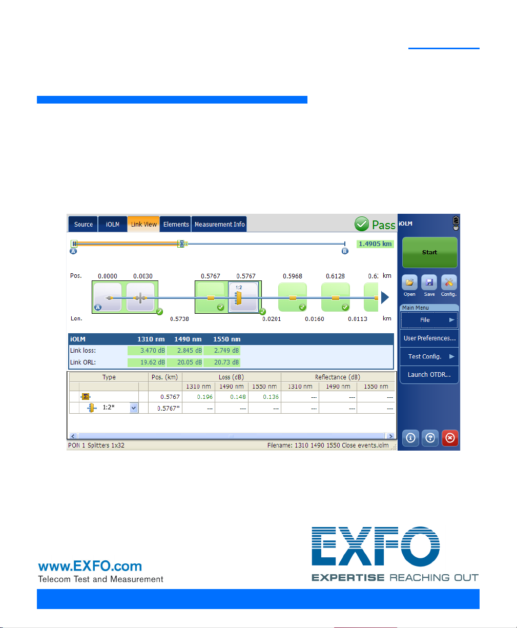
Link View ............................................................................................................................109
Viewing Element and Section Details ..................................................................................121
Managing Elements and Analyzing Links (Optional, iOLM EXpert and Loopback Modes) ...125
Measurement Information ..................................................................................................134
13 Managing Files ..........................................................................................137
Opening iOLM Files .............................................................................................................137
Saving iOLM Files ................................................................................................................139
Exporting OTDR Bellcore Files .............................................................................................142
Generating a Report ...........................................................................................................145
14 Maintenance ..............................................................................................149
Cleaning EUI Connectors ....................................................................................................149
Recalibrating the Unit .........................................................................................................152
Recycling and Disposal (Applies to European Union Only) ..................................................153
15 Troubleshooting ........................................................................................155
Viewing Online Documentation ..........................................................................................155
Contacting the Technical Support Group ............................................................................156
Viewing Information About the Product .............................................................................157
Transportation ....................................................................................................................158
iv iOLM
Page 5

Contents
16 Warranty ................................................................................................... 159
General Information ...........................................................................................................159
Liability ...............................................................................................................................160
Exclusions ...........................................................................................................................161
Certification ........................................................................................................................161
Service and Repairs .............................................................................................................162
EXFO Service Centers Worldwide ........................................................................................163
A Technical Specifications ........................................................................... 165
FTB-720 ..............................................................................................................................165
FTB-720G ............................................................................................................................166
FTB-730 ..............................................................................................................................167
FTB-730G ............................................................................................................................168
FTB-7300E ..........................................................................................................................169
FTB-7400E ..........................................................................................................................170
MAX-715B ..........................................................................................................................171
MAX-720B ..........................................................................................................................172
MAX-730B ..........................................................................................................................173
Index .............................................................................................................. 175
intelligent Optical Link Mapper v
Page 6

Certification Information
Certification Information
North America Regulatory Statement
This unit was certified by an agency approved in both Canada and the
United States of America. It has been evaluated according to applicable
North American approved standards for product safety for use in Canada
and the United States.
Electronic test and measurement equipment is exempt from FCC part 15,
subpart B compliance in the United States of America and from ICES-003
compliance in Canada. However, EXFO Inc. makes reasonable efforts to
ensure compliance to the applicable standards.
The limits set by these standards are designed to provide reasonable
protection against harmful interference when the equipment is operated in
a commercial environment. This equipment generates, uses, and can
radiate radio frequency energy and, if not installed and used in accordance
with the user guide, may cause harmful interference to radio
communications. Operation of this equipment in a residential area is likely
to cause harmful interference in which case the user will be required to
correct the interference at his own expense.
Modifications not expressly approved by the manufacturer could void the
user's authority to operate the equipment.
European Community Declaration of Conformity
An electronic version of the declaration of conformity for your product is
available on our website at www.exfo.com. Refer to the product’s page on
the Web site for details.
vi iOLM
Page 7

1 Introducing the intelligent
Optical Link Mapper
The intelligent Optical Link Mapper (iOLM) is an optimized application for
access/FTTx network characterization. Depending on the iOLM module
configuration, the application can be used before and after network
activation.
The iOLM module can be equipped optionally with an inline power meter.
The power meter is called inline because the acquisition is done using the
SM live port used for iOLM measurements. Optionally, you can measure the
power levels for two wavelengths in a single acquisition, if two
wavelengths are used for testing.
Note: Your screen display may differ slightly from the figures in this user
documentation depending on the platform you are using.
Note: Depending on the model and options you have purchased, some features
may not be available.
Note: In this documentation, the words “tap” and “double-tap” (related to the
use of a touchscreen) replace the words “click” and “double-click”.
intelligent Optical Link Mapper 1
Page 8
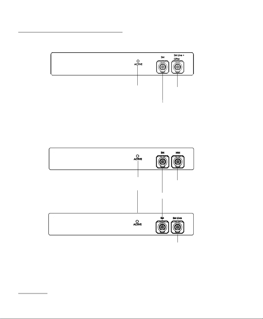
Introducing the intelligent Optical Link Mapper
OTDR port (singlemode)
OTDR port (singlemode
live and On-line power
meter)
Active LED
(ON when laser is emitting)
FTB-720 / FTB-720G / FTB-720G+ for FTB-1
FTB-730 / FTB-730G / FTB-730G+ for FTB-1
OTDR port (singlemode)
OTDR port (multimode)
Active LED
(ON when laser is emitting)
OTDR port
(singlemode live)
2 iOLM
Page 9
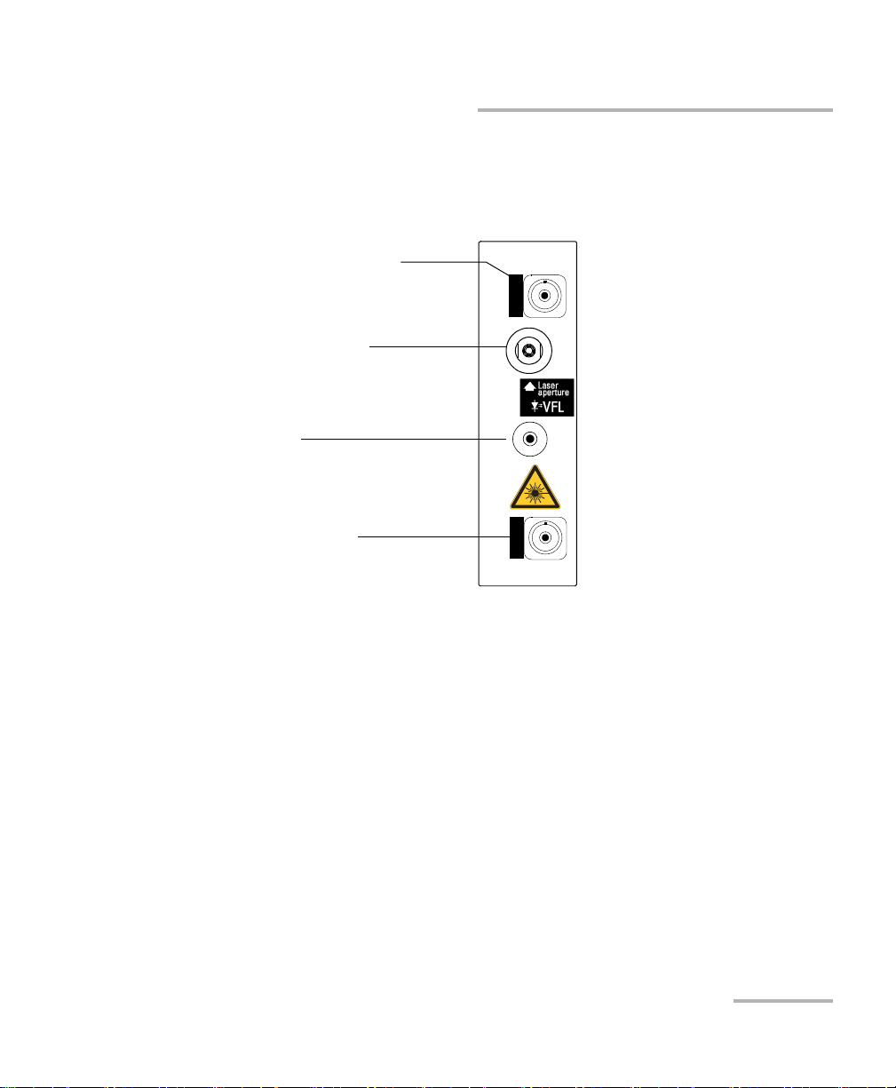
Introducing the intelligent Optical Link Mapper
Handle
Visual fault locator (VFL) port
(optional)
OTDR port (singlemode)
Singlemode and
singlemode live
models
OTDR port (for live-fiber testing)
LIVE
SM OTDR
FTB-7000
SM
SM
FTB-7000 Series for FTB-2, FTB-200V2 and FTB-500
intelligent Optical Link Mapper 3
Page 10
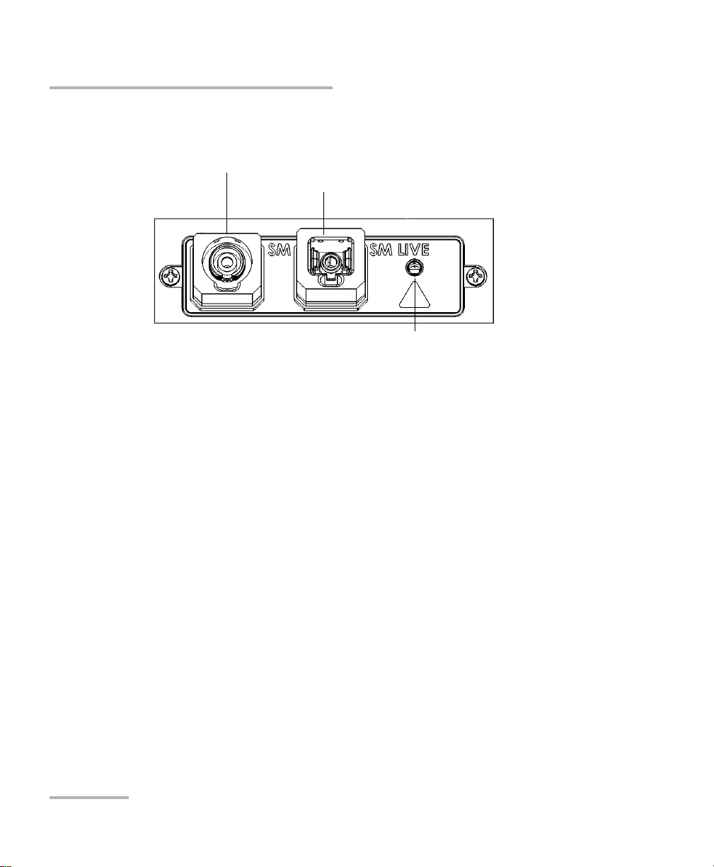
Introducing the intelligent Optical Link Mapper
OTDR port (singlemode live)
OTDR port (singlemode)
Active LED
(on when laser is emitting)
MAX-700B Series
4 iOLM
Page 11

Introducing the intelligent Optical Link Mapper
Principles of Operation
Principles of Operation
The iOLM application uses the hardware of an EXFO OTDR to perform
acquisitions and characterize the various elements detected on the probed
link. However, while a regular OTDR takes one averaged trace at a time,
with one given set of test parameters, the iOLM takes a series of
measurements and integrates them into a simple and intuitive Link View.
The test parameters for each sub-measurement are determined by smart
algorithms during the measurement. Just as each link is different, each
iOLM measurement is different, with its own set of test parameters
according to the link length, loss, and ORL. Test time varies depending on
the link tested, but is mostly influenced by total link loss. The application
uses information from all sub-measurements to enhance the
characterization of each element found on the link, yielding accurate and
complete results. Depending on the module configuration, you can
perform a single or multiple-wavelength acquisition. In the latter case,
results will be provided for each wavelength, and a global pass/fail status
for each element is displayed.
The application summarizes the results in a linear representation of the
link, displaying each element with its associated position, loss and
reflectance, as well as the element type.
Exporting Data to Other Formats
The iOLM application can generate report in various formats and allow
batch post-processing of the measurement. The test configuration files can
be created from FastReporter and imported on each test unit.
intelligent Optical Link Mapper 5
Page 12

Introducing the intelligent Optical Link Mapper
Performing Multimode Measurements
Performing Multimode Measurements
If your module supports multimode measurements, it can test both
62.5 m and 50 m fibers. The internal multimode fiber for an EXFO OTDR
is 62.5 μm.
When a 62.5 μm fiber is connected, the loss at the connector can be
correctly characterized just like in the case of a singlemode fiber. It is
then simple to evaluate a pass/fail criterion in this case.
When a 50 μm fiber is connected, the loss at the connector depends
on many factors:
the connector loss itself
the 62.5 m to 50 μm core fiber difference
the RBS difference between 50 m and 62.5 μm fibers
The measured loss between the OTDR connector and the fiber is
typically around 3.3 dB.
With 50 μm fibers, since the connector loss measurement at the OTDR
is imprecise because of major other factors, the iOLM excludes the first
connector from the link rather than providing inaccurate information.
With a launch fiber, the connector at link start (connector A) is “On-Link”.
When characterizing a multimode link or a singlemode fiber, launch fibers
are recommended. In multimode, the launch and receive fibers must have
the same core size as the link under test. Using an unfitting launch or
receive fiber would lead to inaccurate results.
The use of an external EF-compliant device such as the SPSB-EF-C30 will
ensure a fast and easy way to get accurate loss measurements. For more
information about encircled flux compliance, refer to the encircled flux test
solution specification sheet.
6 iOLM
Page 13

Introducing the intelligent Optical Link Mapper
Launch, Receive, and Loop Fiber
Launch, Receive, and Loop Fiber
Unlike a traditional OTDR, the iOLM requires only a short launch fiber
(>50 m) to benefit from all the advantages of this referencing method,
regardless of the link length and loss. A launch fiber longer than 200 m is
not recommended when testing PON links. Because the output port of an
OTDR may degrade its loss and ORL performances after multiple
connections, the use of a launch cable is always recommended.
The first element of the tested link is tagged with the letter (A) into the link
view. A launch cable allows you to properly characterize the first connector
of the fiber link under test (A) and exclude the OTDR connector's wear
from the link evaluation. A reasonable amount of degradation of the OTDR
connector is acceptable when using an APC interface; the ORL remains
low due to the angle polish, preventing poor near-end resolution. By using
a launch fiber, the OTDR connector loss is excluded from the
measurement. The iOLM evaluates the OTDR connector loss each time a
measurement is performed to inform you about the condition of the
connector. It is important to understand that excessive loss at this
connector will eventually degrade the measurement capabilities of the
instrument. In addition, using a launch cable will help protect your OTDR
connector by limiting the number of connections performed directly on
that connector. It is easier to repair or replace a launch cable than to
replace the OTDR connector.
The last element of the tested link is tagged with the letter (B) into the link
view. A receive fiber cable can be used at the end of the link opposite the
test module in order to characterize the last connector of the link (B) and
increase the precision of the total insertion loss result by comparing
differential level of two known fibers (to avoid errors due to different
backscatter coefficients of the fiber used in the link). If no receive cable is
used, the iOLM application will be able to measure the position and ORL of
this connector in unmatched condition, but not its loss. No pass/fail status
will be displayed for that connector. The required length of the receive
fiber will depend on the loss of the link under test. A higher loss requires a
longer pulse to reach the receive fiber level. Unlike the launch fiber, the
intelligent Optical Link Mapper 7
Page 14

Introducing the intelligent Optical Link Mapper
Launch, Receive, and Loop Fiber
receive fiber has the same limitations than that of a traditional OTDR. Test
of a 1 km fiber span with less than 2 dB of loss will require only 100 m of
receive fiber. Testing a 23 dB PON link will require a receive fiber of 500 m
to 2 km, depending on the fiber length after each splitter.
The iOLM application allows you to manually set the lengths of both your
launch and receive cables. In addition, it is possible to automatically
measure the launch or receive cables. When carrying out the calibration,
the application will perform a fast measurement and evaluate length of the
fiber. For this reason, only the cable under test must be connected to the
module when performing a calibration.
If link elements are found on the fiber under calibration or if the OTDR
connector is defective, the calibration will fail and a warning is displayed to
explain the reason for the failure. A short patchcord (<5 m) is accepted
between the instrument and the fiber under calibration and will be
included in the calibrated length. If the calibration is successful, the launch
or receive fiber length will be updated in the Test Parameters tab.
When performing a measurement, the iOLM will try to match the defined
launch and receive fibers with elements found on the link to set the A and
B connector positions. If no events are found at specified distances
because of a “perfect” connection between link and launch or receive
fibers, the iOLM will insert an element at a specified position (with zero
loss and ORL).
8 iOLM
Page 15

Introducing the intelligent Optical Link Mapper
Launch, Receive, and Loop Fiber
The loopback measurement is designed to test duplex cables.
In a loopback measurement, one end of the first fiber is connected to the
iOLM through a launch fiber, while the other end is connected to the
second fiber using a fiber called a loop. Usually, a receive fiber is used on
the proximal end of the second fiber. The loop fiber can be viewed as a
receive fiber for the first fiber (the one the iOLM is connected to) and a
launch fiber for the second fiber.
The loopback process performs one single acquisition for both fibers, then
automatically splits the result, providing independent measurements for
both fibers in the duplex cable.
The automatic split of the initial measurement can only be performed if the
length of the launch, loop and receive fibers are properly specified in the
application.
See Configuring your iOLM on page 42 for more details.
intelligent Optical Link Mapper 9
Page 16

Introducing the intelligent Optical Link Mapper
Software Options
Software Options
Software options are offered with your unit.
The iOLM software option gives you access to the iOLM application.
The iCERT software option gives you access to the certification
configuration files, which give you a pass/fail status based on industry
standards. This pass/fail status is ensured by the fact that thresholds are
not editable.
The iEX (iOLM EXpert) software option activates edition of links and
custom elements, 2:N splitters, and link reanalysis.
The Loopback (LB) software option allows you to perform iOLM
loopback measurements. This type of measurement loops two fibers
together at one end to test both fibers at once.
The Source (SRC) software option allows you to use your iOLM as a
source. This option is already included on all platforms. However, on
MAX-700B platforms, the option is available for purchase.
10 iOLM
Page 17

Introducing the intelligent Optical Link Mapper
Conventions
Before using the product described in this guide, you should understand
the following conventions:
WARNING
Indicates a potentially hazardous situation which, if not avoided,
could result in death or serious injury. Do not proceed unless you
understand and meet the required conditions.
CAUTION
Indicates a potentially hazardous situation which, if not avoided,
may result in minor or moderate injury. Do not proceed unless you
understand and meet the required conditions.
CAUTION
Indicates a potentially hazardous situation which, if not avoided,
may result in component damage. Do not proceed unless you
understand and meet the required conditions.
Conventions
IMPORTANT
Refers to information about this product you should not overlook.
intelligent Optical Link Mapper 11
Page 18

Page 19
2 Safety Information
WARNING
Do not install or terminate fibers while a light source is active.
Never look directly into a live fiber and ensure that your eyes are
protected at all times.
WARNING
The use of controls, adjustments and procedures, namely for
operation and maintenance, other than those specified herein may
result in hazardous radiation exposure or impair the protection
provided by this unit.
IMPORTANT
When you see the following symbol on your unit , make sure
that you refer to the instructions provided in your user
documentation. Ensure that you understand and meet the required
conditions before using your product.
IMPORTANT
Other safety instructions relevant for your product are located
throughout this documentation, depending on the action to
perform. Make sure to read them carefully when they apply to your
situation.
intelligent Optical Link Mapper 13
Page 20

Safety Information
Affixed to module’s side or back panel
Laser Safety Information (Units Without a VFL)
Laser Safety Information (Units Without a VFL)
Your instrument is a Class 1M laser product in compliance with standards
IEC 60825-1: 2007 and 21 CFR 1040.10, except for deviations pursuant to
Laser Notice No. 50, dated June 24, 2007. Invisible laser radiation may be
encountered at the output port.
Viewing the laser output with certain optical instruments (for
example, eye loupes, magnifiers, and microscopes) within a
distance of 100 mm may pose an eye hazard.
The following label(s) indicate that the product contains a Class 1M source:
WARNING
14 iOLM
Page 21

Safety Information
Laser information of the VFL. Always refer to
the user guide of the MaxTester Series for
the exact information.
Laser information of the test instrument
MaxTester Series
The label is affixed to the back panel of the unit.
Laser Safety Information (Units Without a VFL)
intelligent Optical Link Mapper 15
Page 22

Safety Information
Affixed to module’s or back side panel
Laser Safety Information (Units With a VFL)
Laser Safety Information (Units With a VFL)
Your instrument is a Class 3R laser product in compliance with standards
IEC 60825-1: 2007 and 21 CFR 1040.10, except for deviations pursuant to
Laser Notice No. 50, dated June 24, 2007. Laser radiation is emitted at the
output port. It is potentially harmful in direct intrabeam viewing.
The following label(s) indicate that the product contains a Class 3R source:
For more information on product safety and equipment ratings, refer to the
user documentation of your platform.
All modules power consumption is below 10 W.
16 iOLM
Page 23
3 Getting Started with Your
View Pane
Status Bar
Button Bar,
including
shortcuts to
access the
Open, Save
and
Configuration
selection
menus.
Function
Ta bs
iOLM
Note: Please refer to your platform's or unit’s user guide for detailed information
regarding inserting and removing test modules, and starting applications.
Note: In the case of the FTB-700G Series, you can run only one application at a
time, either NetBlazer or the iOLM application. To start the iOLM
application, from Mini ToolBox, select the OTDR module, then tap the
button corresponding to the desired application. To start the NetBlazer
application, refer either to the Transport Application user guide or to the
Ethernet/Packet Sync/FC/Wireless user guide for more information.
Note: Some features for this application are enabled when you purchase the
iOLM EXpert, RT and source options. For details on how to activate an
option, refer to your platform’s or unit’s user guide.
Main Window
The main window allows you to start the acquisition and view
measurement results and values.
intelligent Optical Link Mapper 17
Page 24

Getting Started with Your iOLM
Name of the current loaded iOLM file.
The loaded file name and the next file
name turns into a progress bar during
the acquisition.
Name of the
current
configuration file.
Status Bar
Status Bar
The status bar, located at the bottom of the main window, identifies the
selected configuration file name in the application, acquisition wavelength
(when an acquisition is in progress), and the acquisition progress bar of the
iOLM. It also displays the next file name according to the autonaming
scheme. For more information, see Naming iOLM Files Automatically on
page 33.
Note: When an acquisition is not in progress, the file name of the file currently
present in memory is displayed.
18 iOLM
Page 25

4 Preparing your iOLM for a Test
Cleaning and Connecting Optical Fibers
IMPORTANT
To ensure maximum power and to avoid erroneous readings:
Always inspect fiber ends and make sure that they are clean as
explained below before inserting them into the port. EXFO is
not responsible for damage or errors caused by bad fiber
cleaning or handling.
Ensure that your patchcord has appropriate connectors. Joining
mismatched connectors will damage the ferrules.
To connect the fiber-optic cable to the port:
1. Inspect the fiber using a fiber inspection microscope. If the fiber is
clean, proceed to connecting it to the port. If the fiber is dirty, clean it as
explained below.
2. Clean the fiber ends as follows:
2a. Gently wipe the fiber end with a lint-free swab dipped in isopropyl
alcohol.
2b. Use compressed air to dry completely.
2c. Visually inspect the fiber end to ensure its cleanliness.
intelligent Optical Link Mapper 19
Page 26

Preparing your iOLM for a Test
Cleaning and Connecting Optical Fibers
3. Carefully align the connector and port to prevent the fiber end from
touching the outside of the port or rubbing against other surfaces.
If your connector features a key, ensure that it is fully fitted into the
port’s corresponding notch.
4. Push the connector in so that the fiber-optic cable is firmly in place,
thus ensuring adequate contact.
If your connector features a screwsleeve, tighten the connector
enough to firmly maintain the fiber in place. Do not overtighten, as this
will damage the fiber and the port.
Note: If your fiber-optic cable is not properly aligned and/or connected, you will
notice heavy loss and reflection.
EXFO uses good quality connectors in compliance with EIA-455-21A
standards.
To keep connectors clean and in good condition, EXFO strongly
recommends inspecting them with a fiber inspection probe before
connecting them. Failure to do so will result in permanent damage to the
connectors and degradation in measurements.
20 iOLM
Page 27
Preparing your iOLM for a Test
Green border
indicates APC
option
2 3 4
Installing the EXFO Universal Interface (EUI)
Installing the EXFO Universal Interface (EUI)
The EUI fixed baseplate is available for connectors with angled (APC)
polishing. A green border around the baseplate indicates that it is for
APC-type connectors.
IMPORTANT
EXFO strongly recommends to only use APC module connectors.
To install an EUI connector adapter onto the EUI baseplate:
1. Hold the EUI connector adapter so the dust cap opens downwards.
2. Close the dust cap in order to hold the connector adapter more firmly.
3. Insert the connector adapter into the baseplate.
4. While pushing firmly, turn the connector adapter clockwise on the
baseplate to lock it in place.
intelligent Optical Link Mapper 21
Page 28

Page 29
5 Setting User Preferences
The User Preferences window allows you to set general settings,
identification settings, and select the power meter mode.
Note: The preference settings are user specific.
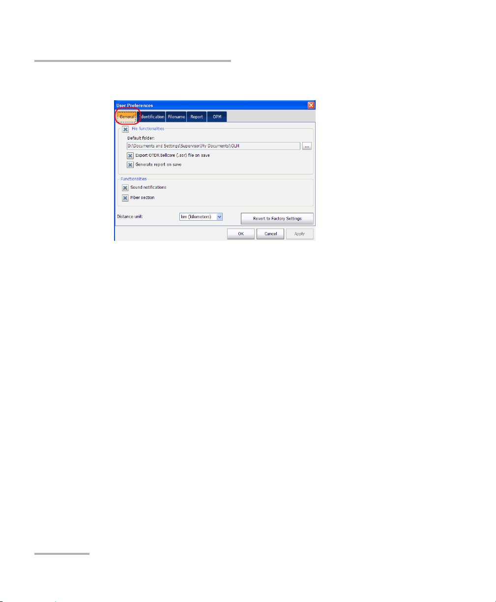
Defining General Settings
The General tab allows you to enable/disable items such as sound, fiber
section information, file functionalities, whether you save a report upon
saving files and export the file to OTDR Bellcore (.sor) format, and set the
distance unit for the application.
To set general settings:
1. From the Main Menu, tap User Preferences.
intelligent Optical Link Mapper 23
Page 30
Setting User Preferences
Defining General Settings
2. Select the General tab.
3. Under the General tab, configure the following settings:
File Functionalities: If enabled, any user interface control related
to file functionalities (for example, Default path, Export OTDR
bellcore file, Generate report on save, Open, Save, Filename, etc.)
will be visible on the screen.
Note: If the File Functionalities option is disabled, the application does not notify
you with the warning message when files are saved. When File
Functionalities is disabled, the Default folder, Export OTDR Bellcore
(.sor) file on save, and Generate Report options are also disabled.
File Save Path: Enter the location for saving the files. This path is
used to save the iOLM files and OTDR Bellcore (.sor) files after an
acquisition.
Note: The default path provided by the operating system is used to save the files
the first time you start an acquisition.
24 iOLM
Page 31

Setting User Preferences
Defining General Settings
Export OTDR Bellcore (.sor) file on save: If enabled, an OTDR
Bellcore (.sor) file is generated for each wavelength whenever the
iOLM measurement is saved. The wavelength value that is
appended to the filename and it is separated with an “_”
(underscore).
Note: The Bellcore (.sor) fails if the iOLM measurement doesn’t contain the
necessary intermediate OTDR data, or if the iOLM acquisition process is
interrupted by the user, or it is self interrupted because of a live fiber is
present in iOLM measurement.
Generate Report on Save: If enabled, the report is automatically
saved each time the measurement is saved.
Note: You can also generate a report by selecting Report in the File menu.
Distance Unit: Select the distance unit from the drop-down menu.
Note: The units displayed in the application and report depend on the unit
selected here.
Sound Notification: If enabled, you will hear a sound when the
unit detects important events.
Fiber section(s): If enabled, you can select the section in the link
view and the corresponding details of the selected section are
displayed in the Elements table.
Tap Revert to Factory Settings to remove all the changes and apply the
default values.
intelligent Optical Link Mapper 25
Page 32

Setting User Preferences
Defining Measurement Identification
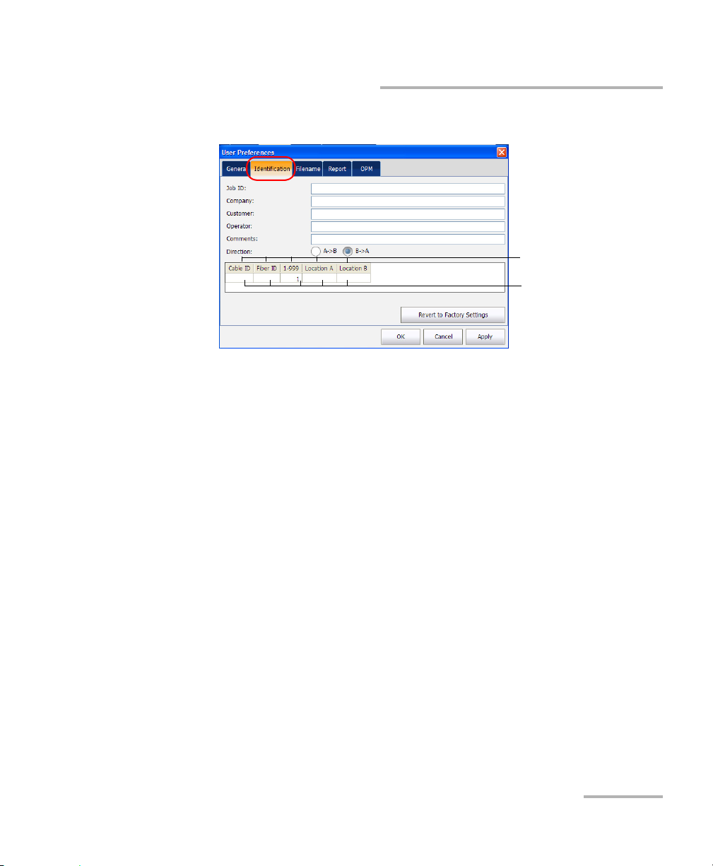
Defining Measurement Identification
You can define the measurement identification information, that is, job ID,
company information, customer name, name of the operator, and
comments for the future acquisition in the Identification tab. The
identifiers defined in the Link Definition tab are also displayed here (see
Modifying Link Definition on page 54 for more details).
To enter identification information:
1. From the Main Menu, tap User Preferences.
26 iOLM
Page 33
Setting User Preferences
Identifiers and range define
in the Identifiers tab
Numeric and alphanumeric
values
Defining Measurement Identification
2. Select the Identification tab.
3. Define the identification information as needed.
The range describes the auto-increment start and stop values for the
identifiers. It is specified in the Identifiers tab under the Test
Configuration window.
The file name generated for future acquisitions will contain the
combination of the numeric and alphanumeric values specified in the
respective fields. For more information on file autonaming, see
Naming iOLM Files Automatically on page 33.
4. Select the direction of the iOLM file from the Direction option.
5. Ta p Apply to save the changes.
6. Ta p OK to save the changes and close the window, or tap Cancel to
exit without saving.
Tap Revert to Factory Settings to remove all the changes and apply the
default values.
intelligent Optical Link Mapper 27
Page 34

Setting User Preferences
Customizing the File Name
Customizing the File Name
The application provides a way to define the name of the file to be saved.
Defining a file autonaming format allows you to quickly and automatically
name the files in a sequential order. The customized file name appears
when the file is saved. It is possible to select which fields you want to
include in the file name and the order in which it should be displayed. With
the loopback option, the direction can be appended to the name of the file.
To customize the file name:
1. From the Main Menu, tap User Preferences.
28 iOLM
Page 35

Standard measurement
Loopback measurement
Setting User Preferences
Customizing the File Name
2. Select the Filename tab.
intelligent Optical Link Mapper 29
Page 36

Setting User Preferences
Customizing the File Name
3. Select which component you want to include in the file name from the
list of available choices:
Job ID: indicates the Job ID configured in the Preferences under
the Identification tab.
Wavelength(s): indicates the current iOLM and power meter
wavelengths.
Identifiers: indicates the identifier value configured in the
Preferences under the Identification tab.
Note: The identifier value is automatically incremented after a new acquisition is
successfully saved using Save option. The Save As option will not
increment the identifier value automatically.
4. Tap Up ( ) or Down ( ) to change the order in which the
components will appear in the file name.
30 iOLM
Page 37

Setting User Preferences
Customizing the File Name
5. If you have the loopback (LB) software option, under Loopback
properties, select Append “From/To” to append the direction to the
name of the file.
Based on the items you have selected, a preview of the file name is
displayed under Preview. The components are separated with an “_”
(underscore).
Note: If you do not select any file component, the Save As window appears even
when you tap Save.
intelligent Optical Link Mapper 31
Page 38

Setting User Preferences
Customizing the File Name
6. Ta p Apply to save the changes.
7. Ta p OK to save the changes and close the window, or tap Cancel to
exit without saving.
Tap Revert to Factory Settings to remove all the changes and apply the
default values.
Note: If the “Wavelengths” file name component is selected, then all of the iOLM
wavelengths present in the iOLM measurement are added to the file name.
When the power meter level is present in the measurement, power meter
wavelengths are added to the file name. For example, if the wavelength is
the only file name component selected under the Filename tab, the iOLM
measurement is done at 1625 nm and the power meter measurement is
done at 1490 nm + 1550 nm, then the file name will be
“1625_1490 + 1550.iolm”.
32 iOLM
Page 39

Setting User Preferences
Name of the
current
configuration file
Next file name
Naming iOLM Files Automatically
Naming iOLM Files Automatically
Each time you start an acquisition, the application suggests a next file
name based on autonaming settings.
The application displays the next file name in the status bar in the following
scenarios:
When the application is started for the first time, the status bar displays
the next file name. You can change the name of the next file through
the Filename tab. When you load the iOLM file the application displays
the corresponding file name in the status bar.
When the acquisition is complete and the file is not saved, the next file
name is displayed. Once the file is saved the application displays the
file name.
The application displays the file name in the Status bar, after the file is
saved.
Note: All the file name components are enabled in this example. See Customizing
the File Name on page 28 to enable file name components.
intelligent Optical Link Mapper 33
Page 40

Setting User Preferences
Naming iOLM Files Automatically
Consider the figure below as an example of autonaming feature.
You can find the above window at Tes t Con f ig. > Manage > Modify >
Identifiers tab.
In the figure above, you can modify the identifiers, start, stop, and step
values and enable the auto increment of the identifier values. See
Modifying Identifiers on page 52 for more details on how to specify the
start, stop, and step values.
You can select the number of digits displayed for the incremented or
decremented values.
Select "#" if you want to keep the value exactly in the same format as
defined in the start and stop values. If a value is to be incremented from 1
to 10, it becomes 1, 2, 3, ... 9, 10. One "#" is the default format.
34 iOLM
Page 41
Setting User Preferences
Naming iOLM Files Automatically
Select two, three, or four "#" if you want all values to be expressed with the
same number of digits. The application fills the empty spaces with zeros
before the increment or decrement to ensure the appropriate format is
displayed. For example, if you select two "#" and the value is to be
incremented from 1 to 10, it becomes 01, 02, 03, ... 09, 10.
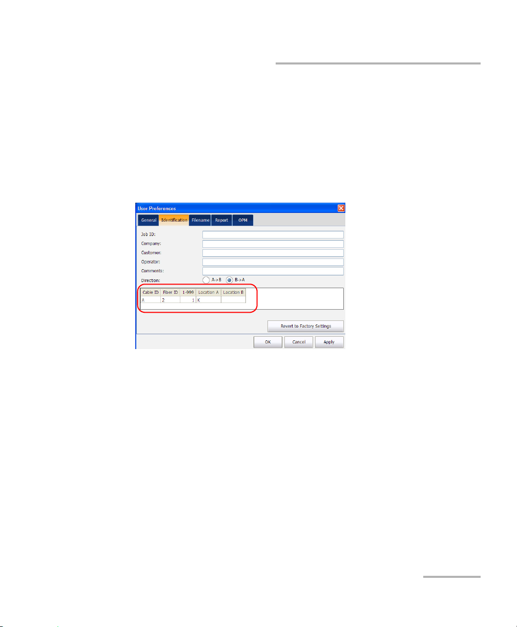
Note: The identifiers defined in the Identifiers tab are displayed in the
Identification tab of the User Preferences window.
You can find the above window at User Preferences > Identification tab.
In the figure above, you can specify the values of the identifiers, such as
OLT as A, OLT measurement range as 2, ONT as B, and so on.
Note: By default, the start values specified in the Identifiers tab are displayed in
the measurement range in the table under User Preferences in the
Identification tab. See Defining Measurement Identification on page 26 for
more details.
intelligent Optical Link Mapper 35
Page 42

Setting User Preferences
Naming iOLM Files Automatically
After an acquisition is successfully saved, the file name is the combination
of job ID, identifiers, and the wavelength. These values are separated in the
file name with an “_” (underscore).
For example, the file name after the first acquisition is
<Job ID>_A2_B1_K3_<wavelength>.iolm
Note: If the ONT, OLT, and location values are not specified, then the file name
will only contain the Job ID value, numeric identifiers value, and the
wavelength.
After a new acquisition is successfully saved, the location value will
increment by the set step value, that is, for the second acquisition file
name, the location value will be 6.
So, the file name after the second acquisition can be
<Job Id>_A2_B1_K6_<wavelength>.iolm
When the location value reaches the stop value, it resets to start value and
ONT value starts incrementing by step value.
The auto increment of values proceeds from right to left.
Note: The auto increment continues until the first number (that is, OLT value)
reaches the stop value.
36 iOLM
Page 43

Setting User Preferences
Customizing the iOLM Report
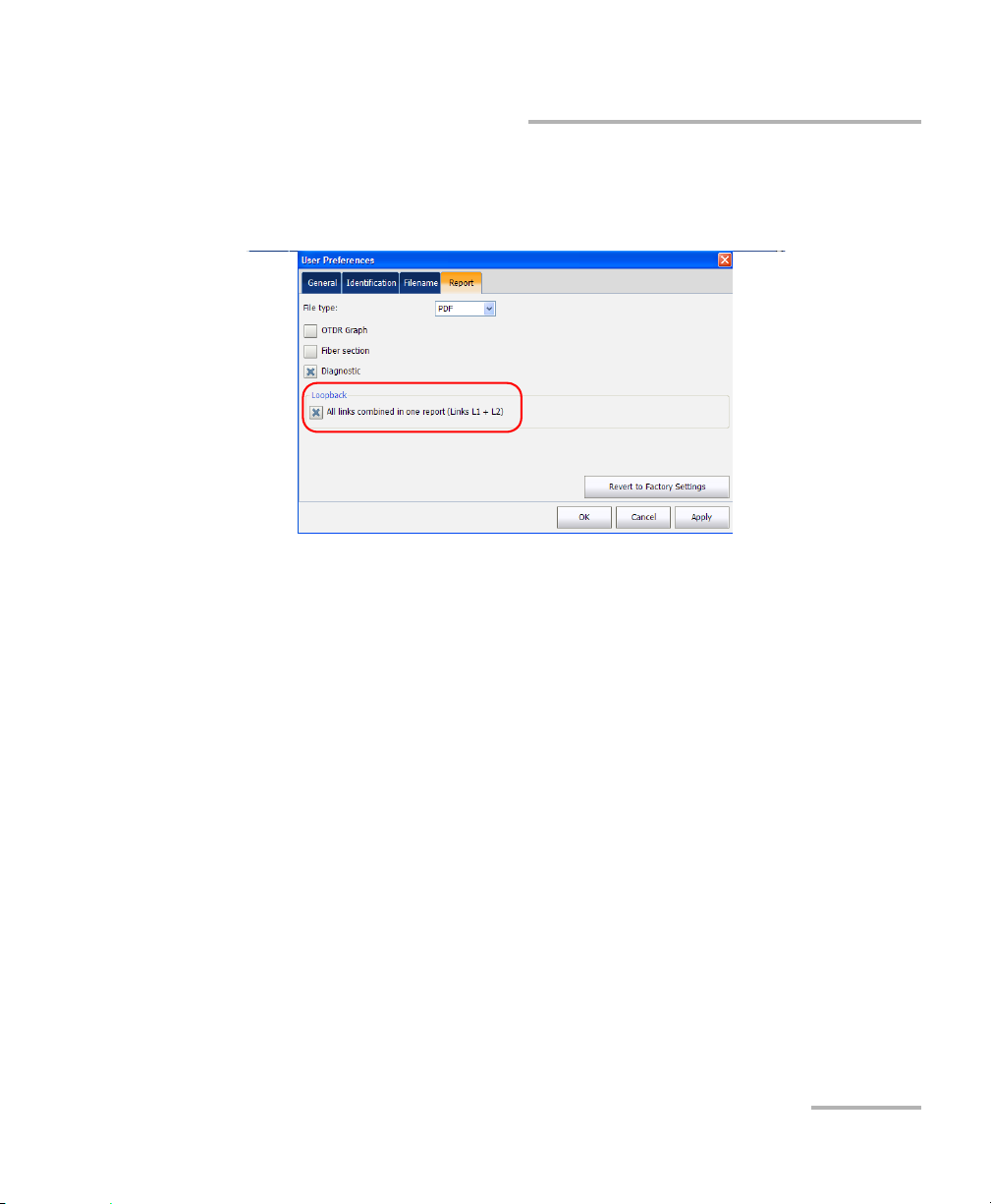
Customizing the iOLM Report
The application allows you to personalize the iOLM report.
Note: You can only generate PDF reports for loopback measurements.
To customize the iOLM report:
1. From the Main Menu, tap User Preferences.
2. Select the Report tab.
intelligent Optical Link Mapper 37
Page 44

Setting User Preferences
Customizing the iOLM Report
3. If your unit allows it, select the report file type from File type option.
4. Select the OTDR Graphic option to display the OTDR graph in the
iOLM report.
Note: The OTDR graph generation fails if the iOLM measurement does not
contain the necessary intermediate OTDR data, or if the iOLM acquisition
process is interrupted by the user, or it is self interrupted because of a live
fiber is present in iOLM measurement.
5. Select Fiber section(s) option to display the section information in the
iOLM report.
6. Select Diagnostic option to display the diagnostics information in the
iOLM report.
38 iOLM
Page 45
Setting User Preferences
Customizing the iOLM Report
7. If you have the loopback (LB) software option, under Loopback, select
the checkbox if you want to generate a report with all links combined
in one report.
Tap Revert to Factory Settings to remove all the changes and apply the
default status.
intelligent Optical Link Mapper 39
Page 46

Setting User Preferences
Customizing the Optical Power Meter
Customizing the Optical Power Meter
The OPM tab is available when an inline power meter is available in the
module. This tab allows you to select the power meter mode which affects
the available wavelengths in the OPM tab of the main window.
To customize the Optical Power Meter:
1. From the Main Menu, tap User Preferences.
40 iOLM
Page 47

Setting User Preferences
Customizing the Optical Power Meter
2. Select the OPM tab.
3. Select the power meter mode. The choices are FTTx/PON and CWDM.
Note: The wavelengths available in the OPM tab are those used for the selected
power meter mode.
4. Ta p Apply to save the changes.
5. Ta p OK to save the changes and close the window, or tap Cancel to
exit without saving.
Tap Revert to Factory Settings to remove all the changes and apply the
default values.
intelligent Optical Link Mapper 41
Page 48

Setting User Preferences
Configuring your iOLM
Configuring your iOLM
The iOLM tab displays the settings used for taking measurements. The
iOLM performs the acquisition on the port and wavelengths selected in the
iOLM tab; the values are preserved for the next acquisition.
The loopback mode allows you to test two fibers at once, which saves time
and manipulations. If you have activated the loopback option for your
application, it is ready to use when needed.
When working in loopback mode, there are three rules to follow so the
loopback can give appropriate results:
Both fibers under test and connected to the loop must have the same
length.
The launch and receive lengths must be specified correctly.
The length of the loop must be specified correctly.
The loopback measurement is especially designed for testing cables
formed of a pair of identical fibers of an equivalent length. The measuring
time is optimized because two fibers are checked in a single
measurement.
Note: Files created using the loopback mode cannot be used to perform a second
loopback operation again.
42 iOLM
Page 49

Setting User Preferences
Configuring your iOLM
To configure the iOLM:
1. From the main window, select the iOLM tab.
2. If two ports are available on your module, select which one to use for
your test. The fiber core is also selected at this point; for C fibers, select
50 m, and for D fibers, select 62.5 m.
3. Select the wavelengths for the next acquisition. The available
wavelengths depend on the iOLM module.
intelligent Optical Link Mapper 43
Page 50
Setting User Preferences
Configuring your iOLM
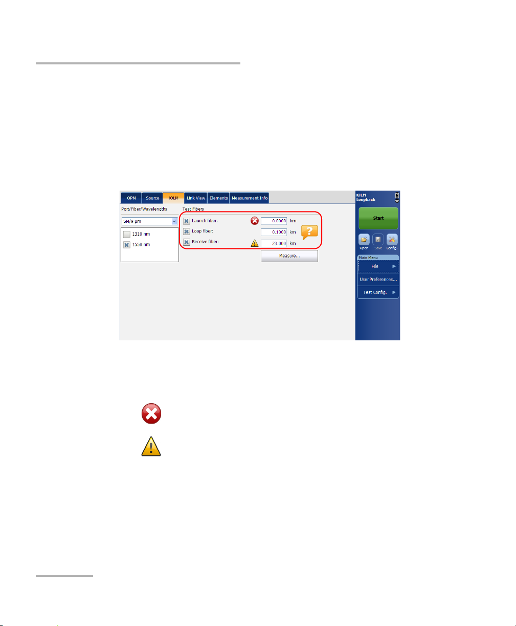
4. Specify if a launch and receive fibers are connected to the link under
test, and enter their lengths. The acceptable range is from 0 to 5 km for
the launch fiber and 0 to 500 km for the receive fiber. See Launch,
Receive, and Loop Fiber on page 7 for more details.
If you have the loopback (LB) software option and if you want to test in
loopback mode, select the loop fiber checkbox. Specify the loop fiber
length at this point. The range is from 0 to 5 km.
When specifying a launch and a receive fibers, as well as a loop fiber, two
different icons may appear when the fiber length is out of the
recommended range. If you tap on the icons, the application then suggests
the appropriate values.
The appears if the provided values are required but not selected
and if the values entered are not within the appropriate range.
The is displayed if the values are not within the appropriate
range.
The help icon opens a window suggesting the appropriate fiber length for
an expected link loss. The icon is not available when a non-supported
configuration is selected.
If you want to automatically calibrate the launch and receive fiber lengths,
tap Measure. You have to specify the loop fiber manually.
44 iOLM
Page 51

6 Managing Test Configurations
This section explains the procedure to select, create, view and modify the
test configuration.
Selecting a Test Configuration
The test configuration is selected to apply the configuration settings
(thresholds, link definition parameters, etc.) in the iOLM application for the
next acquisition.
There are two types of configuration files that are activated with the iCERT
software option.
Note: These configurations do not contain splitters, therefore they are not suitable
for testing PON links.
The configuration files that do comply to the certification standard are
indicated with a blue bubble with a “c” in the middle ( ).
The EXFO configuration files do not comply with the certification
standard.
intelligent Optical Link Mapper 45
Page 52

Managing Test Configurations
Selecting a Test Configuration
To select the test configuration:
1. From the Main Menu, tap Te s t Co n fig .
2. Ta p Select.
46 iOLM
Page 53

3. Select the test configuration file.
Name of the identifiers present in the
file. When more than one identifier is
present, they will be separated by a
semicolon.
Split ratio which is defined for
each stage of the splitter
defined. When more than one
splitter is defined, they will be
separated by a semicolon.
Configuration files which are
not PON are indicated by "---”.
Name of the
configuration
file.
Managing Test Configurations
Selecting a Test Configuration
Note: If you have selected any measurement where 2:N is available, then it is
displayed as Read Only mode in the Test Configuration Selection dialog
box even if the iOLM EXpert option is not activated
Note: Tap on the column to sort the column in ascending or descending order. By
default, the configuration list will be sorted in ascending order according to
the Name column.
4. Select the test configuration from the list of available choices.
5. Ta p OK to apply the configuration and close the window, or tap Cancel
to exit without applying changes.
intelligent Optical Link Mapper 47
Page 54

Managing Test Configurations
Impacts of Test Configurations
Impacts of Test Configurations
Before performing an acquisition, you can select or edit a test configuration
that fits the link under test. This configuration contains specific pass/fail
thresholds and the definition of any expected PON splitter. Once selected,
the configuration will be used for all following measurements.
The configuration data is structured in the same way than an iOLM result
file. Each result file contains the entire configuration data used for the
measurement.
Using a test configuration may influence the minimum reach of the
measurement in terms of loss. For instance, the expected loss budget of a
link that includes splitters will force the acquisition to cover at least this
loss budget. Because of this, using an accurate test configuration can
improve the accuracy of the measurements. If an inaccurate configuration
file is used, some link element types might be wrongly defined. For
instance, if no splitter stage is defined, actual splitters will be described as
splices or connectors. This will not affect the reflectance and loss values
associated with the link elements, only their type. After a measurement is
completed, a link element type can be changed in order to apply the
correct pass/fail threshold.
The pass/fail thresholds defined in the configuration file will have no
impact on the capacity of the iOLM application to perform measurements.
Only the pass/fail status of the link or link elements will be determined by
the user-defined thresholds.
48 iOLM
Page 55
Managing Test Configurations
Creating a Test Configuration
Creating a Test Configuration
The Duplicate button allows you to create a copy of a selected
configuration file.
To create a copy of test configuration:
1. From the Main Menu, tap Te s t Co n fig.
intelligent Optical Link Mapper 49
Page 56

Managing Test Configurations
Creating a Test Configuration
2. Select Manage.
3. Select the test configuration file to duplicate.
4. Ta p Duplicate.
50 iOLM
Page 57

Managing Test Configurations
Modifying a Test Configuration
5. The default file name is displayed. You can modify the file name, if
required.
6. Ta p Save to save the file or tap Cancel to exit without saving.
Note: A number between parenthesis will be automatically incremented at the
end of the file name to avoid unwanted overwrites.
A new copy of the selected configuration file is created. You can
modify the duplicated file, if required. See Modifying a Test
Configuration on page 51 for more details.
7. Ta p Close to close the window.
Modifying a Test Configuration
The Modify button in the Manage main menu allows you to view the
selected configuration file and modify it, if required.
Note: The test configuration settings will be effective for the next acquisition.
Note: If the default factory settings file, or any predefined file is selected, the
Modify button will appear as View, which means that you cannot modify
the factory test configuration files. Also, you cannot modify the files created
by the supervisor, if you are logged in the module as a operator or any user
with lower privileges than supervisor.
intelligent Optical Link Mapper 51
Page 58

Managing Test Configurations
Modifying a Test Configuration
Modifying Identifiers
The Identifiers tab allows you to view and modify the identifier values.
To modify Identifiers:
1. From the Main Menu, tap Te s t Co n fig .
2. Select Manage.
52 iOLM
Page 59

Managing Test Configurations
Modifying a Test Configuration
3. Select the test configuration file to modify.
4. Ta p Modify.
The name of the configuration is displayed on the title bar of the
window.
5. Select the Identifiers tab.
intelligent Optical Link Mapper 53
Page 60

Managing Test Configurations
Modifying a Test Configuration
6. Under Identifiers, select the identifiers from the list of available
choices.
Note: Two identifiers cannot have the same name.
7. Under Auto Increment, enable or disable the auto increment option. It
enables the numeric part of the identifiers to be
incremented/decremented after the acquisition has been saved
successfully.
8. Enter the start, stop, and step values for the identifier under Start, Stop,
and Step.
Note: The Step value must be smaller than the difference between the Start and
Stop values. If the Start is greater than the Stop, then the identifier value
begins decrementing by the specified Step.
9. Ta p OK to save the changes and close the window, or tap Cancel to
exit without saving.
Tap Revert to Factory Settings to remove all the changes and apply the
default values associated with the selected configuration.
Modifying Link Definition
The Link Definition tab allows you to view and modify the link definition.
The links defined in the Link Definition tab are based on the network
topology. For example, if there are 2 splitters present in the PON network,
you may define two stages of splitter with their respective split ratio. You
may change the IOR value, or change or rename the identifiers according
to the network, which will help you to identify where the measurement is
done in the PON network. The modifications will be applicable for future
acquisitions.
Note: Splitters are available only for PON configurations.
54 iOLM
Page 61

Managing Test Configurations
To modify link definition:
1. From the Main Menu, tap Te s t Co n fig.
2. Select Manage.
Modifying a Test Configuration
intelligent Optical Link Mapper 55
Page 62

Managing Test Configurations
Modifying a Test Configuration
3. Select the test configuration file to modify.
4. Ta p Modify.
The name of the configuration is displayed on the title bar of the
window.
5. Select the Link Definition tab.
56 iOLM
Page 63

Managing Test Configurations
Modifying a Test Configuration
6. Select the split ratio of a splitter at a given stage.
Select 1:? if the splitter ratio is unknown. The iOLM finds the splitter
ratio automatically and the element is not tested for pass/fail.
If None is selected as Splitter Ratio Stage, then the iOLM will not try to
find or apply a split ratio at the given stage.
The PON network can have multiple splitters. The iOLM application
supports testing a PON network having maximum of three splitters. So,
the splitter ratios can be defined up to three stages.
Note: The splitter ratios are defined at different stages, depending on how they
are defined in the network.
Note: The link view displays the link element closest to the iOLM module to the
left and then proceeds towards the right.
Core size: When a multimode port is selected, the default fiber
core size is 50 m.
IOR: Refraction index of the iOLM measurement, also known as
group index. If you modify this parameter, the distance
measurements for the trace will be adjusted.
Backscatter (dB): Rayleigh backscatter coefficient setting of the
iOLM measurement. If you modify this parameter, the reflectance
and ORL measurements for the trace will be adjusted.
Note: For the multimode wavelengths, the values are defined at 850 nm. For the
singlemode wavelengths, the values are defined at 1550 nm. The iOLM
application automatically calculates the IOR and Backscatter values for
other wavelengths.
intelligent Optical Link Mapper 57
Page 64

Managing Test Configurations
Modifying a Test Configuration
7. Ta p OK to save the changes and close the window, or tap Cancel to
exit without saving.
Tap Edit Custom Elements to add, edit, or delete the custom element. For
more information, see Managing Custom Elements (Optional, iOLM EXpert
Mode Only) on page 63. If the iOLM EXpert option is not activated, you can
view the custom element present in the test configuration by tapping View
Custom Elements.
Tap Revert to Factory Settings to apply the default values associated with
the selected configuration.
Note: Revert to Factory Settings does not change the modifications done in the
Edit Custom Element.
58 iOLM
Page 65

Managing Test Configurations
Modifying a Test Configuration
Enabling 2:N Splitters (Optional, iOLM EXpert
Mode Only)
The 2:N splitter can be used to create network redundancy. If a network
break occurs, the operator can connect through the other network branch.
This ensures active communication while the repairing of the broken
network is in progress.
If the 2:N splitter is selected for the Splitter ratio stage 1 field and the test
configuration is imported on a unit where the iOLM EXpert is not activated
then the 2:N splitter is automatically replaced by 1:N splitter. For example, if
in the test configuration stage 1 is selected as 2:128 and the iOLM EXpert
option is deactivated, then it is automatically replaced by 1:128.
In the Splitter ratio stage 1 field, if 1:? or None is selected and you have
enabled the 2:N splitter option, then the 1:? and None are replaced by a
splitter value of 2:2.
Note: The threshold for the 2:N splitter is displayed in the Element P/F
Thresholds tab only if the 2:N splitter is selected in Link Definition tab.
intelligent Optical Link Mapper 59
Page 66

Managing Test Configurations
Modifying a Test Configuration
To enable the 2:N splitter:
1. From the Main Menu, tap Te s t Co n fig > Manage.
2. Select the test configuration file to modify from the test configuration
list file.
3. Ta p Modify.
60 iOLM
Page 67

Managing Test Configurations
Modifying a Test Configuration
4. Select the Link Definition tab from the test Configuration.
5. Enable 2:N splitter.
6. Select the required ratio from Splitter ratio stage 1.
7. Ta p OK to save your changes or Cancel to discard them.
intelligent Optical Link Mapper 61
Page 68

Managing Test Configurations
Modifying a Test Configuration
The element pass/fail status remains unknown in the following scenarios:
If any element is followed by 2:N splitter in the link then the element’s
loss pass/fail status is displayed as unknown.
If the element has a reflectance value and it is placed after the 2:N
splitter element, then the element’s reflectance pass/fail status is
displayed as unknown.
If the 2:N splitter is in a group of elements and an element follow the
2:N splitter in the group, then the pass/fail status of group is displayed
as unknown.
62 iOLM
Page 69

Managing Test Configurations
Modifying a Test Configuration
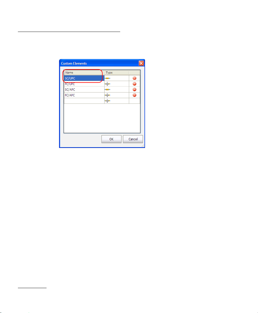
Managing Custom Elements (Optional, iOLM
EXpert Mode Only)
The application allows you to add, modify or delete custom elements
when the iOLM EXpert option is activated. You can add custom elements of
two basic element types: splice or connector. Each custom element must
have its unique name. You can view and edit the element’s pass/fail
threshold of the custom element in the Element P/F Threshold tab.
If the iOLM EXpert option is not activated, then you will not be able to edit
the element pass/fail threshold for the custom element and if the
measurement file contains custom elements, the custom elements are
displayed in the Element P/F Threshold tab under the Measurement
Settings.
To add a custom element:
1. From the Main Menu, select Te s t Co n fig . > Manage.
2. Select the test configuration file to modify.
3. Ta p Modify.
intelligent Optical Link Mapper 63
Page 70

Managing Test Configurations
Modifying a Test Configuration
4. Ta p Link Definition > Edit Custom Elements.
5. Enter the custom element name under the Name column in the
Custom Elements dialog box. The name of the custom element can
contain a maximum of 12 characters.
6. Select the custom element type under the Type column.
7. Ta p OK to save the changes and close the dialog box, or tap Cancel to
exit without saving.
64 iOLM
Page 71

Managing Test Configurations
Modifying a Test Configuration
To modify the custom element:
1. From the Main Menu, select Te s t Co n fig . > Manage.
2. Select the test configuration file to modify.
3. Ta p Modify.
4. Select Link Definition > Edit Custom Elements.
intelligent Optical Link Mapper 65
Page 72
Managing Test Configurations
Modifying a Test Configuration
5. Select the custom element name under the Name column and modify
it as needed.
6. Select the required custom element type under the Ty pe column.
7. Ta p OK to save the changes and close the dialog box, or tap Cancel to
exit without saving.
66 iOLM
Page 73

Managing Test Configurations
Modifying a Test Configuration
To delete the custom element:
1. From the Main Menu, select Te s t Co n fig . > Manage.
2. Select the test configuration file to modify.
3. Ta p Modify.
4. Select Link Definition > Edit Custom Elements.
intelligent Optical Link Mapper 67
Page 74

Managing Test Configurations
Modifying a Test Configuration
5. Tap the or icon (depending on the unit) beside the custom
element which you want to delete.
6. Ta p OK to save the changes and close the dialog box, or tap Cancel to
exit without saving.
68 iOLM
Page 75

Managing Test Configurations
Modifying a Test Configuration
Modifying Link Pass/Fail Thresholds
This tab allows you to apply modification to the link pass/fail thresholds. If
the selected wavelength is Any, the values edited will be applied to all the
wavelengths present.
Note: Pass/Fail thresholds cannot be viewed or edited for some configurations
related to specific standards.
To modify link pass/fail thresholds:
1. From the Main Menu, tap Te s t Co n fig.
intelligent Optical Link Mapper 69
Page 76

Managing Test Configurations
Modifying a Test Configuration
2. Select Manage.
3. Select the test configuration file to modify.
4. Ta p Modify.
70 iOLM
Page 77

Managing Test Configurations
Modifying a Test Configuration
5. Select the Link P/F Thresholds tab.
6. Under Link P/F Thresholds, modify the following parameters, as
needed.
Link Length: Select the link length threshold type from the
available choices and then modify the link length as required.
Note: The minimum link length cannot be greater than the maximum link length.
Wavelength: Select the wavelength for which the different
Pass/Fail threshold values can be specified. The available choices
of the wavelength depend on the iOLM module.
Link Loss: Select the Link Loss threshold type from the available
choices and then modify the link loss as required.
Note: The minimum link loss cannot be greater than the maximum link loss.
Link ORL: Select the Link ORL (Optical Return Loss) threshold
type from the available choices and then modify the link ORL as
required. The optical return loss (ORL) refers to the total effect of
multiple reflections and scattering events within a fiber-optic
system.
intelligent Optical Link Mapper 71
Page 78

Managing Test Configurations
Modifying a Test Configuration
7. Ta p OK to save the changes and close the window, or tap Cancel to
exit without saving.
Tap Revert to Factory Settings to remove all the changes and apply the
default values associated with the selected configuration.
Modifying Element Pass/Fail Thresholds
This tab allows you to apply modifications to the element pass/fail
thresholds.
Note: Pass/Fail thresholds cannot be viewed or edited for some configurations
related to specific standards.
To modify element pass/fail thresholds:
1. From the Main Menu, tap Te s t Co n fig .
72 iOLM
Page 79

Managing Test Configurations
2. Select Manage.
3. Select the test configuration file to modify.
4. Ta p Modify.
Modifying a Test Configuration
intelligent Optical Link Mapper 73
Page 80

Managing Test Configurations
Modifying a Test Configuration
5. Select the Element P/F Thresholds tab.
The Threshold column displays the threshold values for Splice,
Connector, and Splitter ratios (1:N and 2:N) for each available
wavelength in the test configuration settings. The custom elements are
displayed in the group under Max. connector loss or Max. connector
reflectance or Max. splice loss. This information is also displayed in the
iOLM report.
74 iOLM
Page 81

Managing Test Configurations
Modifying a Test Configuration
6. Enable the Apply pass/fail option to access the parameters, and
modify them as needed. You can add, edit, and delete the custom
element by tapping on the custom element. For steps to modify or
create custom elements, see Managing Custom Elements (Optional,
iOLM EXpert Mode Only) on page 63.
Note: The pass/fail thresholds of the custom elements can only be edited when
the iOLM EXpert option is activated.
Note: The available wavelength choices depend on the iOLM module.
7. Ta p OK to save the changes and close the window, or tap Cancel to
exit without saving.
Select Apply to all wavelengths to display the common threshold values
for all the wavelengths. If any threshold has different values for its
wavelengths, then the cell will be empty.
Tap Revert to Factory Settings to remove all the changes and apply the
default values associated with the selected configuration.
intelligent Optical Link Mapper 75
Page 82

Managing Test Configurations
Modifying a Test Configuration
Modifying Power Meter Pass/Fail Thresholds
This tab allows you to modify the power meter pass/fail thresholds.
Note: The OPM P/F Thresholds tab will only be available if an inline power
meter is present in the module.
To modify power meter pass/fail thresholds:
1. From the Main Menu, tap Te s t Co n fig .
76 iOLM
Page 83

Managing Test Configurations
2. Select Manage.
3. Select the test configuration file to modify.
4. Ta p Modify.
Modifying a Test Configuration
intelligent Optical Link Mapper 77
Page 84

Managing Test Configurations
Modifying a Test Configuration
5. Select the OPM P/F Thresholds tab.
6. Under OPM P/F Thresholds, modify the following parameters, as
needed.
Wavelength: Select the wavelength for which the different
Pass/Fail threshold values can be specified. The available choices
of the wavelength depends on the iOLM module and the Power
Meter settings in the Preferences tab.
Note: The Any wavelength option will be displayed only if more than one
wavelength is present. If Any wavelength is selected, the threshold values
will be applied to all the wavelengths present in the drop-down box.
Power: Select the power threshold type from the available choices
and then modify the power as required.
7. Ta p OK to save the changes and close the window, or tap Cancel to
exit without saving.
Tap Revert to Factory Settings to remove all the changes and apply the
default values associated with the selected configuration.
78 iOLM
Page 85

Managing Test Configurations
Modifying a Test Configuration
Deleting Test Configuration
The Delete button allows you to delete an existing configuration file.
Note: You cannot delete the DefaultSetup configuration or iCERT
standard-compliant configurations.
To delete a test configuration:
1. From the Main Menu, tap Te s t Co n fig.
intelligent Optical Link Mapper 79
Page 86

Managing Test Configurations
Modifying a Test Configuration
2. Select Manage.
3. Select the test configuration file to delete.
4. Ta p Delete.
A confirmation message is displayed.
5. Ta p Yes to delete the file or tap No to cancel the deletion.
6. Ta p Close to close the window.
80 iOLM
Page 87

Managing Test Configurations
Importing or Exporting a Test Configuration
Importing or Exporting a Test Configuration
The Import button allows you to import test configuration from an external
storage device and the Export button allows you to export the selected
configuration to an external storage device.
Note: To import iCERT configurations and its duplicates, you need to activate the
option on the unit.
Note: If a USB device is connected to the module, the default path for
import/export will be the USB device.
To import a test configuration:
1. From the Main Menu, tap Te s t Co n fig.
intelligent Optical Link Mapper 81
Page 88
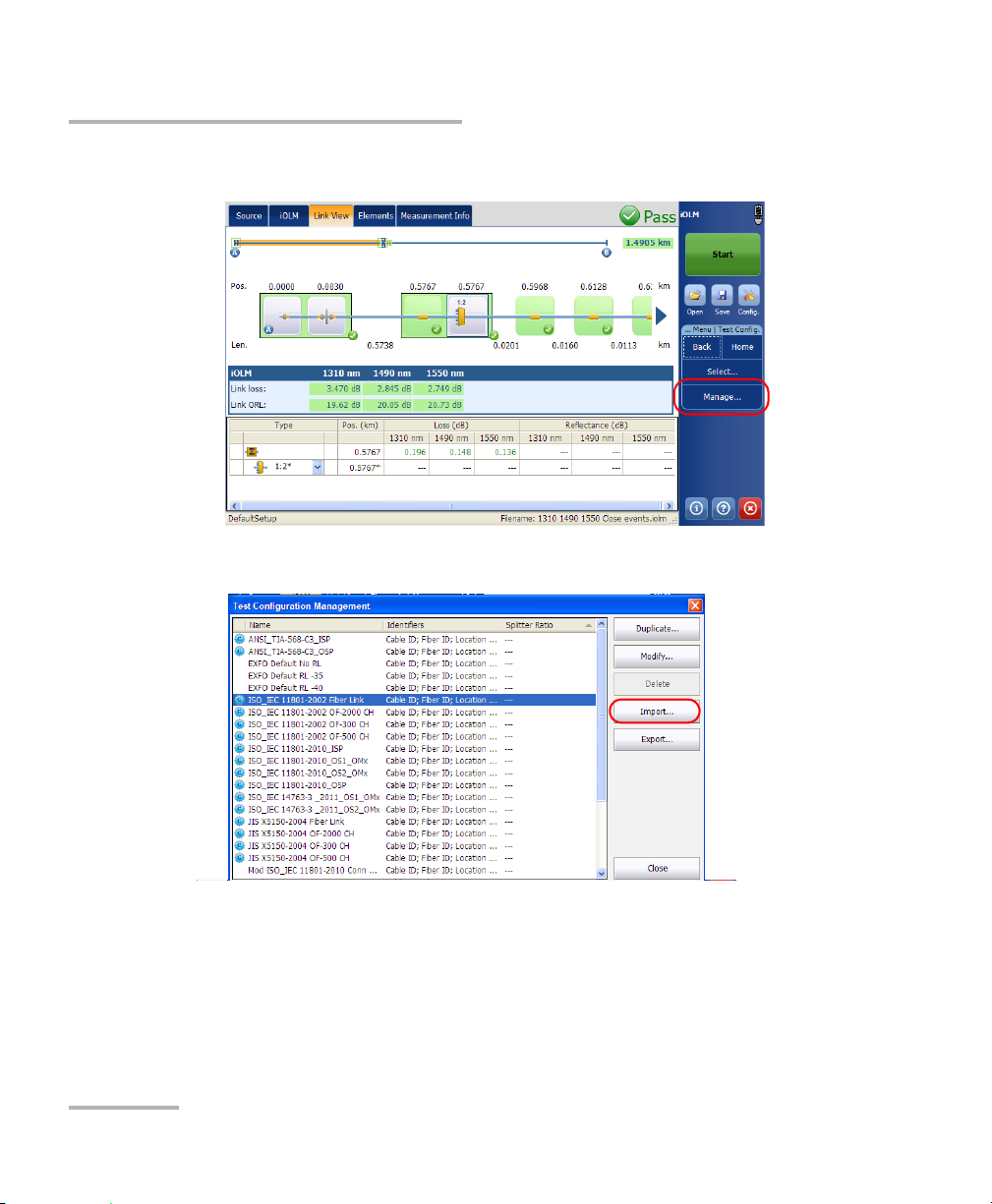
Managing Test Configurations
Importing or Exporting a Test Configuration
2. Select Manage.
3. Ta p Import.
82 iOLM
Page 89

Managing Test Configurations
Importing or Exporting a Test Configuration
4. An Import dialog box opens, select the file to import and tap Open.
Note: Depending on the type of unit you are using, the Open button may be
replaced with an OK button.
A confirmation message is displayed.
5. Ta p Yes to select the file or tap No to cancel the selection.
intelligent Optical Link Mapper 83
Page 90

Managing Test Configurations
Importing or Exporting a Test Configuration
To export a test configuration:
1. From the Main Menu, tap Te s t Co n fig .
2. Select Manage.
84 iOLM
Page 91

Managing Test Configurations
Importing or Exporting a Test Configuration
3. Select the test configuration file.
4. Ta p Export to export the configuration to an external storage device.
5. An Export dialog box opens, select the location and tap Save.
Note: Depending on the type of unit you are using, the Save button may be
replaced with an OK button.
intelligent Optical Link Mapper 85
Page 92

Page 93

7 Starting an Acquisition
This section explains the acquisition process of the iOLM.
Starting an iOLM Acquisition
This section explains the iOLM acquisition process. The iOLM allows you to
characterize a fiber-optic span, usually optical fiber sections joined by
splices and connectors. The iOLM provides an inside view of the fiber, and
can calculate fiber length, breaks, total return loss, splice, connector, and
total losses. For more information on how to perform a loopback
measurement, see Configuring your iOLM on page 42.
To perform an iOLM acquisition:
Tap Start (standard measurement).
The application displays a confirmation message asking to save unsaved
data (if any) before starting a new acquisition.
Note: You will not be asked to save the file if the file functionalities are not
activated. See Setting User Preferences on page 23 for more details.
When an iOLM acquisition starts, the Link View tab is displayed by default.
The progress of the overall acquisition for all wavelengths is displayed in
the status bar. For example, if two wavelengths have to be processed, at
the end of the first wavelength acquisition the overall progress will be 50 %.
The current wavelength is displayed in front of the acquisition progress.
intelligent Optical Link Mapper 87
Page 94

Starting an Acquisition
Starting a Single-Wavelength Acquisition
Starting a Single-Wavelength Acquisition
The single-wavelength acquisition allows you to take an acquisition on a
specific wavelength if multiple wavelengths are present in the module.
To start single wavelength acquisition:
1. If you unit supports it, from the iOLM tab, select the port to use. The
fiber core is selected at the same time as the port. For C fiber, select
50 m and for D fiber, select 62.5 m.
88 iOLM
Page 95

Starting an Acquisition
Starting a Single-Wavelength Acquisition
2. Select the desired iOLM Wavelength(s) (one wavelength).
3. Ta p Start.
intelligent Optical Link Mapper 89
Page 96

Starting an Acquisition
Starting a Multiple-Wavelength Acquisition
Starting a Multiple-Wavelength Acquisition
The multiple-wavelength acquisition allows you to take an acquisition on
multiple wavelengths, if multiple wavelengths are present in the module.
In a multiple wavelength acquisition, the current wavelength in the
acquisition is displayed.
To start multiple wavelength acquisition:
1. From the iOLM tab, select the desired port. The fiber core is selected at
the same time as the port. For C fiber, select 50 m and for D fiber,
select 62.5 m.
90 iOLM
Page 97

Starting a Multiple-Wavelength Acquisition
2. Select the desired iOLM Wavelength(s).
3. Ta p Start.
Starting an Acquisition
intelligent Optical Link Mapper 91
Page 98

Starting an Acquisition
Stopping an Acquisition
Stopping an Acquisition
The acquisition stops automatically after the acquisition is complete.
It is possible to stop the acquisition at any time while the acquisition is in
progress.
Note: The unprocessed wavelengths will not be processed when a multiple
wavelength acquisition is stopped manually.
To stop the acquisition:
Tap Stop from the main window.
The stopped acquisition status will be saved in the measurement file. The
stopped acquisition status is also displayed in the Measurement Info tab.
The global pass/fail status will show unknown or fail when the acquisition
is stopped manually.
Note: A manually stopped acquisition should not be considered as a reliable link
measurement. To fully characterize a link, a complete acquisition should
be performed.
92 iOLM
Page 99

8 Understanding Diagnostics
This section explains the diagnostics feature available in the iOLM
application.
Diagnostics are used to provide additional information about detected
problems or ambiguous measurement situations, such as root cause
possibilities for the fail status of a link element. The diagnostics provide
help to troubleshoot faulty connectors, understand why link elements are
tagged as fail or unknown, indicate unexpected instrument or test
conditions and so forth.
Link elements with an associated diagnostic are marked with an icon,
and the diagnostics are displayed in the Link View and Elements tabs.
More than one diagnostic can be associated with any given element.
Elements diagnostics are associated with specific link elements issues.
Each failed link element will have associated diagnostics to assist in
troubleshooting. Some elements, such as macrobends, will have
associated diagnostics even with a pass status.
intelligent Optical Link Mapper 93
Page 100

 Loading...