

Page 1
Power Meter and VFL
User Guide
Page 2

Copyright © 2010–2013 EXFO Inc. All rights reserved. No part of this
publication may be reproduced, stored in a retrieval system or transmitted
in any form, be it electronically, mechanically, or by any other means such
as photocopying, recording or otherwise, without the prior written
permission of EXFO Inc. (EXFO).
Information provided by EXFO is believed to be accurate and reliable.
However, no responsibility is assumed by EXFO for its use nor for any
infringements of patents or other rights of third parties that may result from
its use. No license is granted by implication or otherwise under any patent
rights of EXFO.
EXFO’s Commerce And Government Entities (CAGE) code under the North
Atlantic Treaty Organization (NATO) is 0L8C3.
The information contained in this publication is subject to change without
notice.
Trademarks
EXFO’s trademarks have been identified as such. However, the presence
or absence of such identification does not affect the legal status of any
trademark.
Units of Measurement
Units of measurement in this publication conform to SI standards and
practices.
Version number: 3.0.0
ii Power Meter and VFL
Page 3

Contents
Contents
1 Introducing the Optional Power Meter and VFL ....................................... 1
Conventions ............................................................................................................................1
Safety Information ..................................................................................................................2
Certification Information ........................................................................................................2
2 Using the Optional Power Meters and VFL ................................................. 3
Nulling Offsets ........................................................................................................................4
Setting Thresholds and Correction Factors ..............................................................................5
Setting Reference Values on Your Power Meter ......................................................................9
Measuring Power or Insertion Loss .......................................................................................10
Saving Results Files ...............................................................................................................17
Opening Result Files .............................................................................................................18
Clearing Measurements from the Display .............................................................................19
Adding Information to Your Results ......................................................................................20
Generating Result Reports ...................................................................................................21
Identifying Fiber Faults Visually with the VFL ........................................................................23
3 Maintenance and Troubleshooting ........................................................... 25
Viewing Online Documentation ............................................................................................25
Installing a Unit You Have Purchased Separately ...................................................................25
Recalibrating the Unit ...........................................................................................................26
Contacting the Technical Support Group ..............................................................................28
Transportation ......................................................................................................................28
4 Warranty ..................................................................................................... 29
General Information .............................................................................................................29
Liability .................................................................................................................................30
Exclusions .............................................................................................................................31
Certification ..........................................................................................................................31
Service and Repairs ...............................................................................................................32
EXFO Service Centers Worldwide ..........................................................................................33
Index ................................................................................................................ 35
Power Meter and VFL iii
Page 4

Page 5

1 Introducing the Optional
Power Meter and VFL
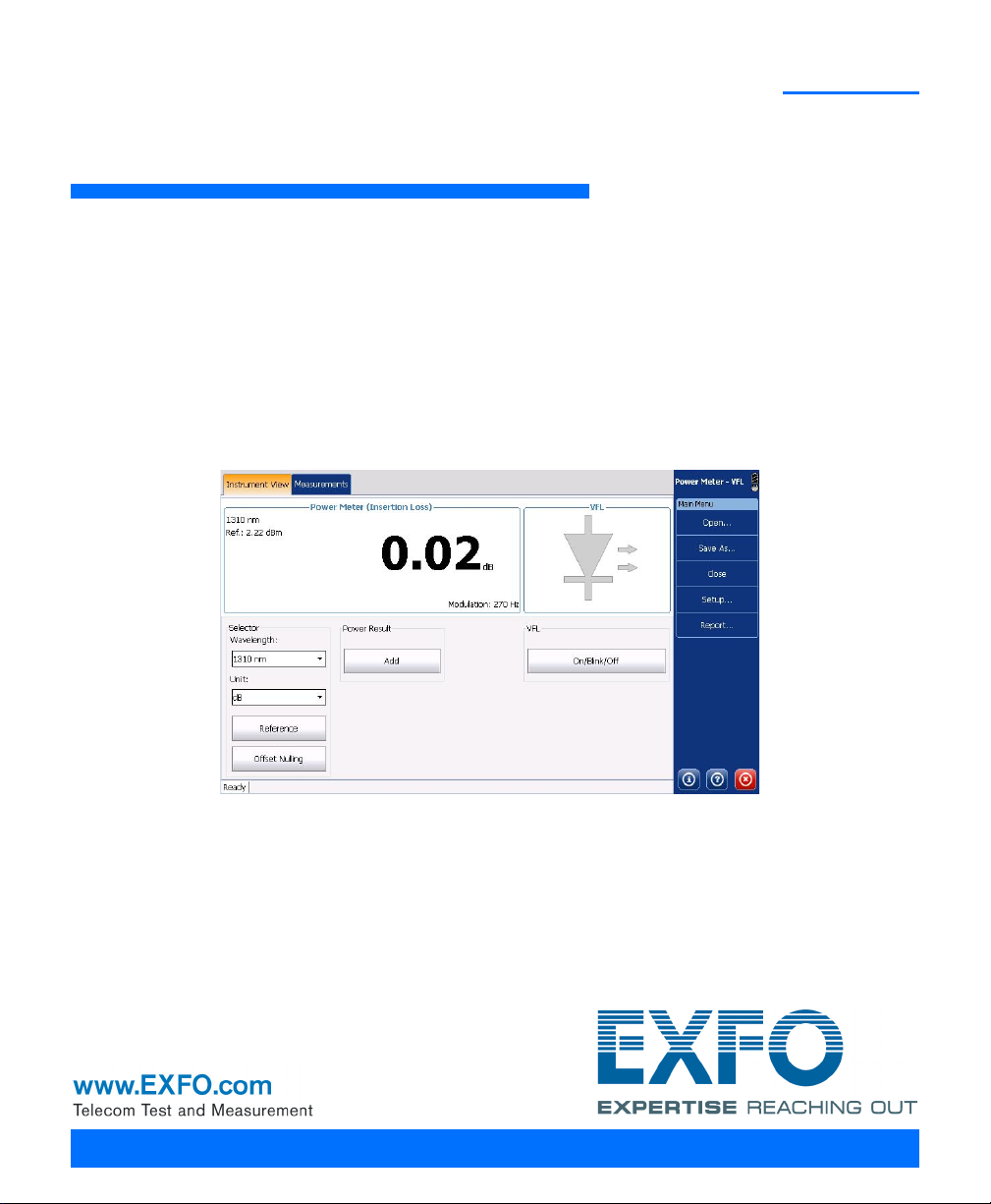
Your unit can be equipped with an optical power meter to measure
absolute power (dBm or W) or insertion loss (dB). The power meter can
detect modulated signals (1 kHz, 2 kHz, 270 Hz and 330 Hz).
The built-in power meter can also include a visual fault locator (VFL) to
inspect or identify fibers.
Conventions
Before using the product described in this guide, you should understand
the following conventions:
WARNING
Indicates a potentially hazardous situation which, if not avoided,
could result in death or serious injury. Do not proceed unless you
understand and meet the required conditions.
CAUTION
Indicates a potentially hazardous situation which, if not avoided,
may result in minor or moderate injury. Do not proceed unless you
understand and meet the required conditions.
CAUTION
Indicates a potentially hazardous situation which, if not avoided,
may result in component damage. Do not proceed unless you
understand and meet the required conditions.
IMPORTANT
Refers to information about this product you should not overlook.
Power Meter and VFL 1
Page 6

Introducing the Optional Power Meter and VFL
Safety Information
Safety Information
The laser and electrical safety information pertaining to your unit is specific
to the unit you are using. Please refer to the corresponding user
documentation for more details.
Certification Information
The certification and declaration of conformity for your unit is specific to
the unit you are using. Please refer to the corresponding user
documentation for more details.
2 Power Meter and VFL
Page 7
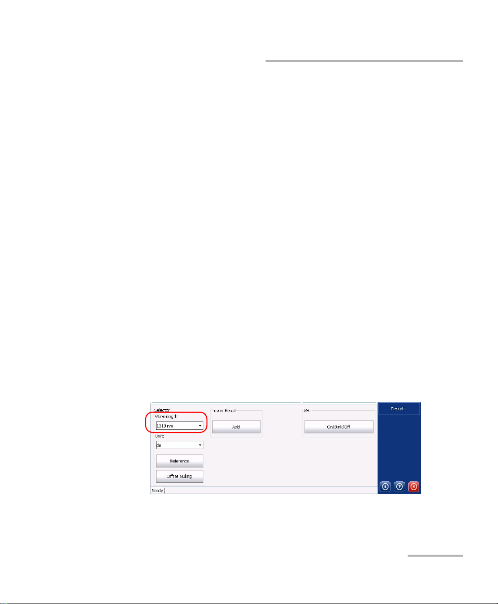
2 Using the Optional Power
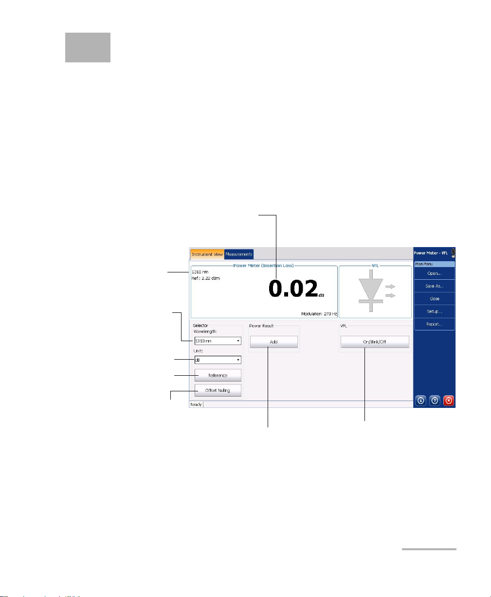
Selected wavelength
To s w i t c h b e tw e e n
available power meter
wavelengths
To take a new reference
measurement
Measured power or insertion loss
To switch between dB, dBm
and W as measurement units
To store a reading to the
Measurements window
To activate VFL and
change VFL mode
To perform an offset
nulling
Meters and VFL
Note: If a feature is only available for one type of power meter, it is indicated
specifically in the corresponding title or instructions.
Note: Some buttons are not available when you first access the Power Meter
application, but will be available after you tap Add for the first time or after
you open a file.
Below is a description of the Power Meter buttons and functions.
Power Meter and VFL 3
Page 8
Using the Optional Power Meters and VFL
Nulling Offsets
Nulling Offsets
Temperature and humidity variations affect the performance of electronic
circuits and optical detectors, which can offset measurement results. To
compensate for this offset, the unit is equipped with an offset nulling
function.
Your unit has been designed not to require offset nulling under normal
operation, but you should perform it whenever environmental conditions
change significantly or when measuring very low power values.
IMPORTANT
Light must not reach the detector when nulling offsets. Always use
an EUI or protective screw cap. Do not use a soft rubber cover.
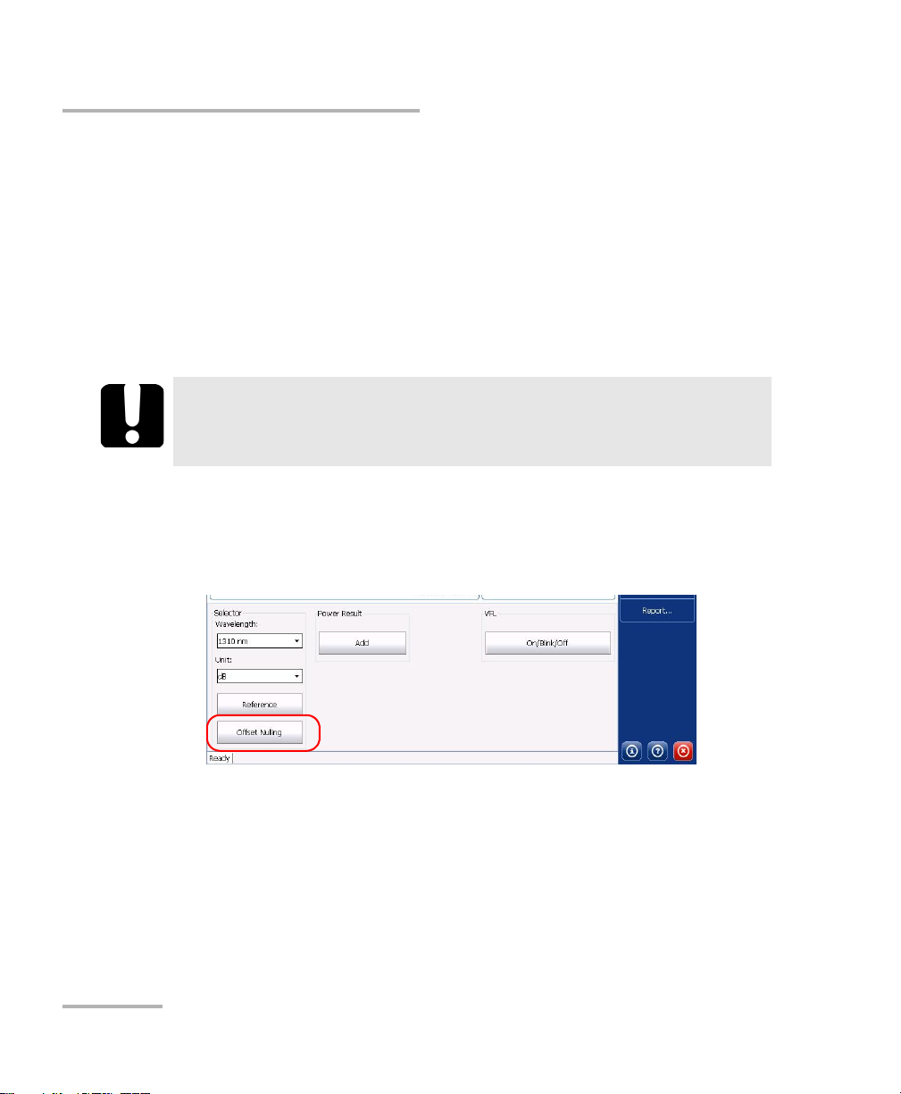
To perform an offset nulling:
1. Tighten the protective cap on the power meter port.
2. From the Instrument View tab, tap Offset Nulling.
The nulling process may take a moment, depending on the type of power
meter you are using.
4 Power Meter and VFL
Page 9

Using the Optional Power Meters and VFL
Setting Thresholds and Correction Factors
Setting Thresholds and Correction Factors
You can define thresholds to specify acceptable power or insertion loss
values for each wavelength. Thresholds are usually supplied by system
manufacturers and depend on the system deployed.
When the measurement status is “Pass”, the value is displayed in green in
the Instrument View tab, on the Measurements list, and in reports.
When the measurement status is “Fail”, the value is displayed in white over
a red background in the Instrument View tab, on the Measurements list
and in reports.
Note: A power measurement (in dBm) will be considered as “Fail” when its value
is outside the defined absolute power threshold.
Note: An insertion loss measurement (in dB) will be considered as “Fail” when its
value is greater than the insertion loss threshold.
You must select the pass/fail status feature for the application to take into
account the defined thresholds and display the appropriate status icons. By
default, this feature is not selected.
Power Meter and VFL 5
Page 10

Using the Optional Power Meters and VFL
Power
corrected
Power
measured
CF=
Setting Thresholds and Correction Factors
You may apply a correction factor (CF) to measured power to compensate
for inaccuracies or drifts. You should change the CF after performing an
offset nulling.
where:
Pow er
Pow er
corrected
measured
= the corrected power value
= the measured power value
CF = the correction factor
For each favorite wavelength, the CF is set to 1.00 at the factory, but
allowed values range between 0.85 and 1.15.
Note: Some other products express the CF in dB, so the CF would be added to
measured power.
IMPORTANT
If you revert to factory settings, you will erase all your thresholds
and correction factors. The pass/fail status feature will be disabled
automatically.
6 Power Meter and VFL
Page 11
Using the Optional Power Meters and VFL
Setting Thresholds and Correction Factors
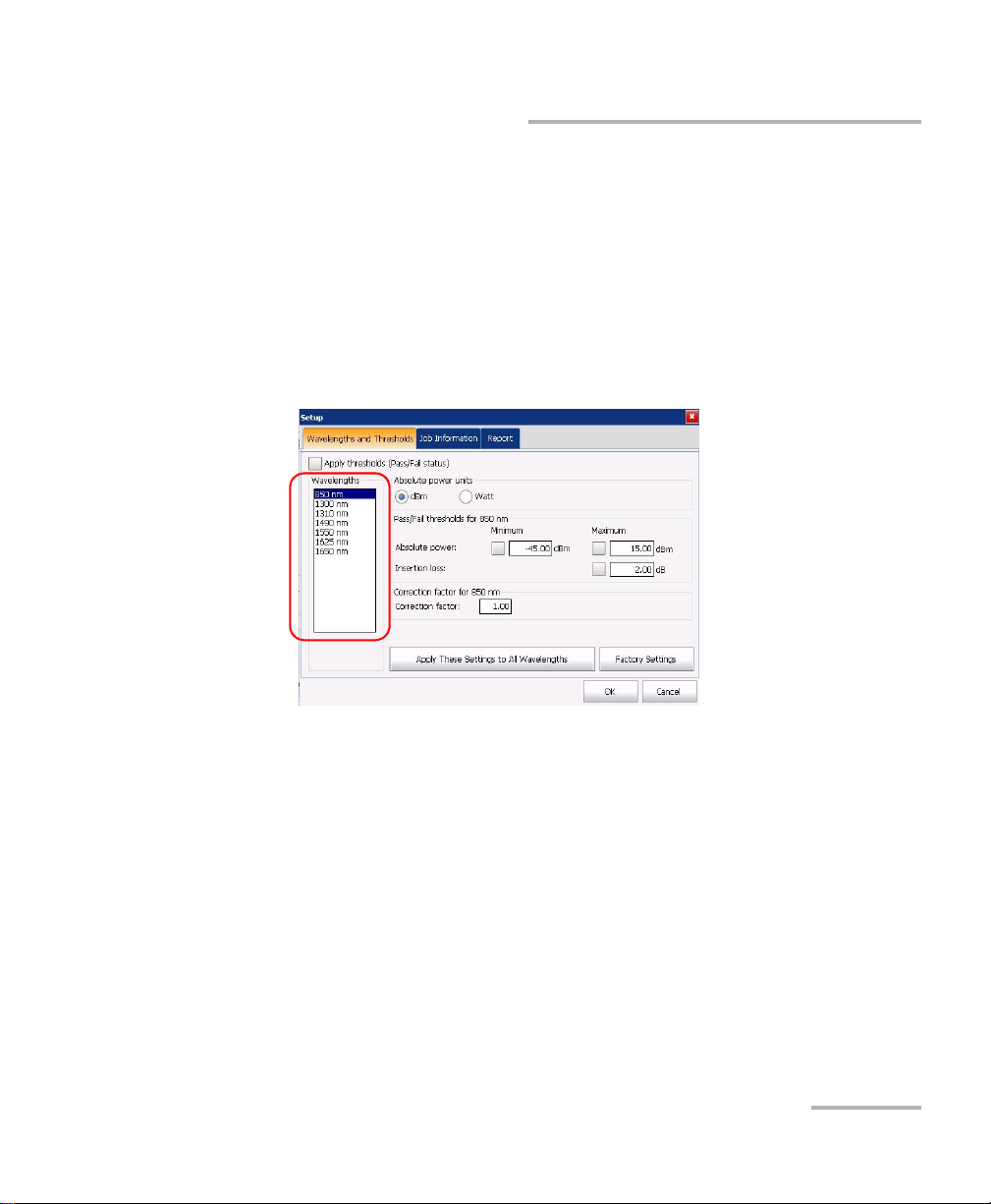
To set thresholds or correction factors:
1. From the Instrument View tab, tap Setup, then select the
Wavelengths and Thresholds tab.
2. Select Apply thresholds (Pass/Fail status) to apply the thresholds and
display the relevant information in the Instrument View tab of the
main window.
3. From the Wavelengths list, select the wavelength for which you want
to set a threshold or a correction factor.
Power Meter and VFL 7
Page 12

Using the Optional Power Meters and VFL
Correction factor for
selected wavelength
To revert to
default values
To m a k e t h e t h r e s ho l d
active for selected
wavelength
To select the units used for the absolute power
value (has no effect on the measurement range)
Setting Thresholds and Correction Factors
4. Modify the thresholds or correction factor for the selected wavelength.
To apply these settings to all of the wavelengths in the list, tap Apply These
Settings to All Wavelengths.
8 Power Meter and VFL
Page 13
Using the Optional Power Meters and VFL
Setting Reference Values on Your Power Meter
Setting Reference Values on Your Power Meter
In Reference mode, your unit displays the loss created by the fiber under
test only, since it subtracts a reference value from the measured power.
You can set a different reference value for each wavelength. A reference
value remains in memory until a new one is stored at the same
wavelength.
If the source and power meter you are using has auto-wavelength or
auto-switching capacity, you can take the reference value automatically for
each wavelength as well.
To set reference values to use in Reference mode:
1. Check your fibers and clean them properly.
2. Using the proper adapter and test jumpers, connect a light source to
your power meter.
3. From the Instrument View tab, select the wavelength in the list.
Activate the source at the same wavelength.
OR
If you want to use the auto-wavelength or auto-switching mode, enable
it on the source, then select Auto in the wavelength list (for more
information on the auto-wavelength or auto-switching mode, see
Measuring Power or Insertion Loss on page 10).
4. Ta p Reference to save the current power value as the new reference. It
will appear on the upper-right corner of the data display.
Power Meter and VFL 9
Page 14

Using the Optional Power Meters and VFL
Measuring Power or Insertion Loss
Measuring Power or Insertion Loss
Measuring absolute power or link (insertion) loss is done the same way,
except for the referencing step. You can take power or insertion loss
measurements and save them for further analysis.
IMPORTANT
If you intend to take measurements with a very low power level
using the built-in power meter, make sure that your testing
conditions are optimal to ensure the best results (for example, do
not use the VFL).
You can either perform measurements manually and select each
wavelength yourself, or you can use the auto-wavelength and
auto-switching modes of your source, if the model allows it.
Note: Not all power meters have auto-wavelength and auto-switching detection
capacities. If the auto mode is not available, you cannot select it in the
Wavlength list. However, if the power meter has the capacity, but the auto
mode is still not available, a firmware update may be required. Please
contact EXFO to see how to proceed to update the firmware.
10 Power Meter and VFL
Page 15

Using the Optional Power Meters and VFL
Measuring Power or Insertion Loss
To perform power or insertion loss measurements manually:
1. If necessary, perform an offset nulling (see Nulling Offsets on page 4).
2. Check your fibers and clean them properly.
3. For insertion loss measurements, reference your power meter to a light
source (see Setting Reference Values on Your Power Meter on page 9),
then deactivate the light source.
4. If you have used a single reference patchcord, disconnect it from the
power meter port only, then attach a second reference patchcord to
the power meter.
OR
If you have used two reference patchcords, disconnect both of them at
the bulkhead.
Power Meter and VFL 11
Page 16

Using the Optional Power Meters and VFL
Measuring Power or Insertion Loss
5. Using bulkhead adapters or the system patch panels, connect a fiber
under test to reference patchcord attached to the light source and
power meter.
6. From the Instrument View tab, use the list to select a wavelength.
Activate the source at the same wavelength.
7. Ta p Add to transfer the displayed values to the Measurements list.
Note: If you tap Add just after switching to another measurement unit, the
application will prompt you to save any unsaved measurements. You must
either save these measurements and close the file, or discard them
(see Clearing Measurements from the Display on page 19) before being
able to add values expressed in the new measurement unit.
8. Repeat the procedure for other wavelengths.
9. Once your work is complete, tap Save.
IMPORTANT
If you specify a name that already exists, the original file will be
overwritten and only the new file will be available.
12 Power Meter and VFL
Page 17

Using the Optional Power Meters and VFL
Measuring Power or Insertion Loss
To perform power or insertion loss measurements using the auto
wavelength or auto switching modes of your source:
1. If necessary, perform an offset nulling (see Nulling Offsets on page 4).
2. Check your fibers and clean them properly.
3. For insertion loss measurements, reference your power meter to a light
source (see Setting Reference Values on Your Power Meter on page 9),
then deactivate the light source.
4. If you have used a single reference patchcord, disconnect it from the
power meter port only, then attach a second reference patchcord to
the power meter.
OR
If you have used two reference patchcords, disconnect both of them at
the bulkhead.
5. Using bulkhead adapters or the system patch panels, connect a fiber
under test to reference patchcord attached to the light source and
power meter.
IMPORTANT
In auto wavelength or switching mode, there is a small delay (about
2 seconds per wavelength) allowed for refreshing the values. When
switching from one fiber to another, wait for these few seconds to
make sure that the measurement you are reading is not a residual
measurement from the previous fiber.
Power Meter and VFL 13
Page 18

Using the Optional Power Meters and VFL
Measuring Power or Insertion Loss
6. From the Instrument View tab, select Auto. Activate the source with
the auto-wavelength or auto-switching mode.
Readings with more than one wavelength appear on-screen at the
same time when the auto-switching feature is enabled on the source.
If the auto-wavelength or auto-switching mode are not activated for
your source, and that you try to use the auto feature of the power
meter, you will be notified clearly in red, and no reading is displayed.
14 Power Meter and VFL
Page 19

Using the Optional Power Meters and VFL
Measuring Power or Insertion Loss
7. Ta p Add to transfer the displayed values to the Measurements list. In
auto-switching mode, the measurements are added for all
wavelengths at once, using one line per wavelength.
Note: If you tap Add just after switching to another measurement unit, the
application will prompt you to save any unsaved measurements. You must
either save these measurements and close the file, or discard them
(see Clearing Measurements from the Display on page 19) before being
able to add values expressed in the new measurement unit.
8. Once your work is complete, tap Save.
IMPORTANT
If you specify a name that already exists, the original file will be
overwritten and only the new file will be available.
Power Meter and VFL 15
Page 20
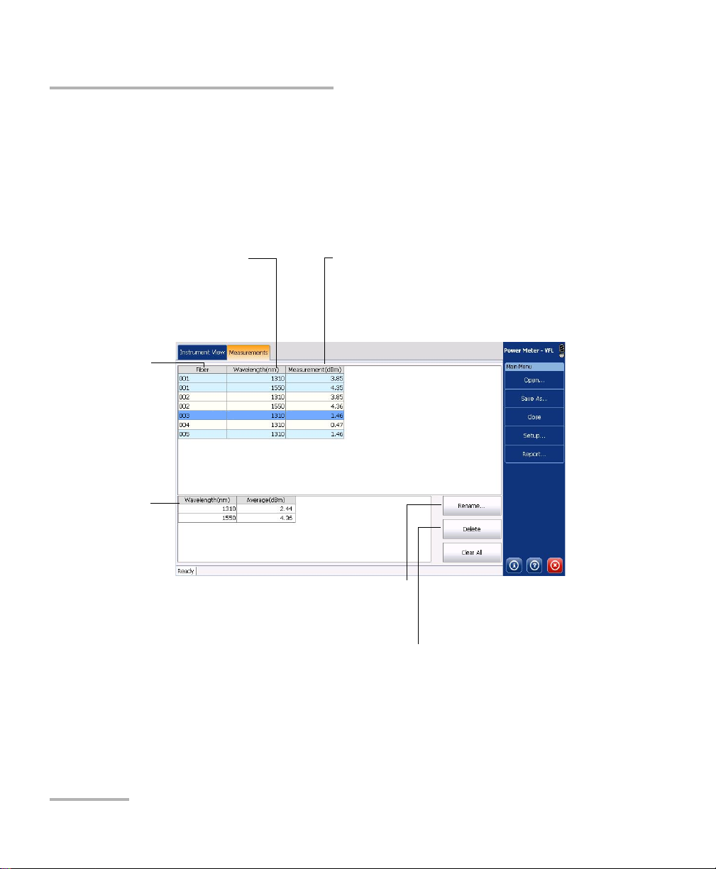
Using the Optional Power Meters and VFL
To change the fiber name (in the case of multiple
wavelengths, they are all changed at the same time)
Fiber name
To delete the selected row from the table (in
the case of multiple wavelengths, they are
all deleted at the same time)
Wavelength at which power or
insertion loss was measured
Insertion loss measurement (in dB) or power
measurement (in dBm)
Average power
or insertion loss
measured per
wavelength
Measuring Power or Insertion Loss
To view and edit power or insertion loss measurements:
1. Select the Measurements tab. All your measurements are displayed in
the order they were performed.
2. Ta p Rename to rename the fiber, tap Delete to remove the selected
value from the list, or Clear All to remove all measurements from the
list.
16 Power Meter and VFL
Page 21

Using the Optional Power Meters and VFL
Saving Results Files
Saving Results Files
Once you have added measurements to your list, you might want to save
them onto a file for future consultation.
To save a measurement file:
1. From the main window, tap Save As.
2. If desired, change the name and location, then tap Save.
Power Meter and VFL 17
Page 22
Using the Optional Power Meters and VFL
Opening Result Files
Opening Result Files
You can open results files that are stored on your unit or on a USB memory
key. If you need more flexibility and a greater choice of report types, you
can also transfer results files to a computer onto which EXFO’s
Fas t Re p or t er i s i ns t al l ed .
IMPORTANT
The file that you will open includes the threshold values and job
information that you had set when you saved that file. These
settings will replace the current settings.
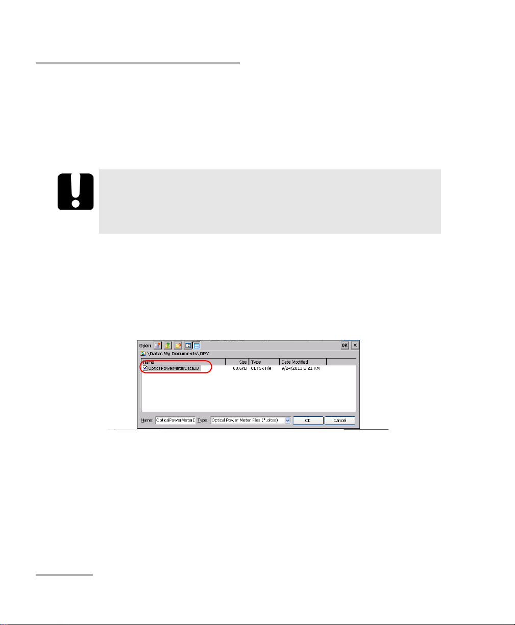
To open results files:
1. From the button bar, tap Open.
2. If necessary, change the location from which the file should be
opened. The application will keep in memory the last selected folder.
3. From the given list of files, select the file to open.
4. Confirm with OK.
If you have already performed power measurements, but not saved
them, the application will prompt you to save your work. You must
either save or discard the unsaved measurements before being able to
open a file.
5. To view the reopened file, go to the Measurements tab. The power or
insertion loss measurements are displayed on the results list.
18 Power Meter and VFL
Page 23
Using the Optional Power Meters and VFL
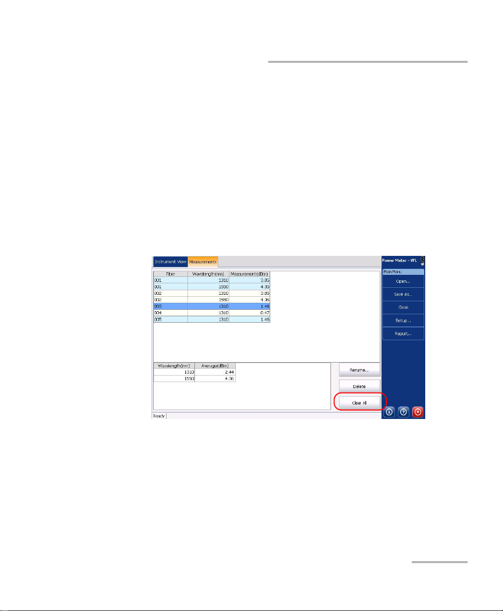
Clearing Measurements from the Display
Clearing Measurements from the Display
When measurements do not meet your requirements, you can clear the
display and start over.
Note: Clearing measurements from the display does not delete them from the
disk (if they were saved previously).
To clear power measurements:
1. From the button bar, tap Close.
OR
From the Measurements tab, tap Clear All.
If you have not saved the measurements already, the application will
warn you that you will lose your work if you continue.
2. When the application prompts you, proceed as follows:
Select Yes if you want to discard your measurements.
OR
Select No if you want to keep them, and then, from the button bar,
tap Save.
Power Meter and VFL 19
Page 24
Using the Optional Power Meters and VFL
Adding Information to Your Results
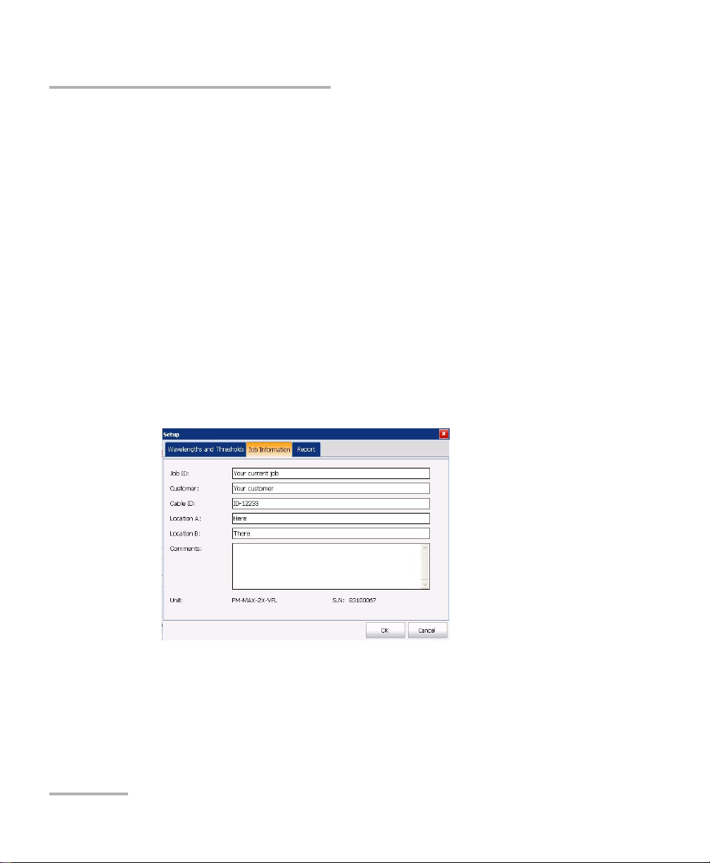
Adding Information to Your Results
A report is available to keep notes on the measurements, the location of
the tested fiber, the type of job performed, and general comments. This
information will be saved, along with your measurements, in the power
meter results file. When you open the results files with applications such as
EXFO’s FastReporter (installed on a computer), all the information that you
entered will be available.
To speed up information entry, once you have provided the required data,
the contents is kept in memory. This information will be used for all new
results.
To add information to your results:
1. From the button bar, tap Setup, and then select the Job Information
tab.
2. Enter information in the appropriate boxes.
3. Ta p OK to confirm.
The information that you have entered will be copied to all the new files
(and reports) that you create.
20 Power Meter and VFL
Page 25
Using the Optional Power Meters and VFL
Generating Result Reports
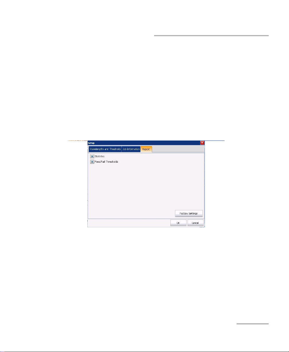
Generating Result Reports
You can generate reports directly from your unit in PDF format.
You can modify the information related to customer, cable and job
(see Adding Information to Your Results on page 20).
Depending on the information you want in your report, you can include the
statistics, the pass/fail thresholds, or both.
To select the items to include in your report:
1. From the main window, tap Setup, then select the Report tab.
2. Select which items you want to include in the reports.
3. Ta p OK to confirm your choice.
Power Meter and VFL 21
Page 26

Using the Optional Power Meters and VFL
Generating Result Reports
To generate a power measurement report:
1. From the button bar, tap Report.
2. If desired, change the location for the file.
3. Enter a name for your file.
4. Ta p OK to save your report.
22 Power Meter and VFL
Page 27

Using the Optional Power Meters and VFL
Identifying Fiber Faults Visually with the VFL
Identifying Fiber Faults Visually with the VFL
The optional visual fault locator (VFL) helps you identify bends, faulty
connectors, splices and other causes of signal loss. It can also help the
person at the other end of the link to identify the fiber under test, which
could be particularly useful when working with cables containing many
fibers.
From its dedicated port, the VFL emits a red signal which becomes visible
at the location of a fault on the fiber. This signal can be continuous (CW) or
blinking (1 Hz).
WARNING
When the VFL is active, the VFL port emits visible laser radiation.
Avoid exposure and do not stare directly into the beam. Protect any
unused port with a cap.
Power Meter and VFL 23
Page 28

Using the Optional Power Meters and VFL
Identifying Fiber Faults Visually with the VFL
To activate the VFL and inspect a fiber:
1. Clean the connectors properly.
2. Connect the fiber under test to the VFL port.
3. If necessary, from Mini Toolbox, on the Main Menu, tap Power Meter
and VFL.
4. Select the Instrument View tab.
5. Ta p ON/Blink/OFF to change the VFL state.
6. Without looking directly into the beam, examine the fiber. If light is
coming out of the rubber jacket or on the side of the ferrule, the fiber is
defective.
24 Power Meter and VFL
Page 29

3 Maintenance and
Troubleshooting
Viewing Online Documentation
An online version of the Power Meter and VFL user guide is available at all
times from the application.
Note: You will also find a printable PDF version on your installation DVD.
To access online help:
At the bottom of the Main Menu, tap .
Installing a Unit You Have Purchased Separately
If you have purchased your power meter unit separately, please refer to the
corresponding unit user documentation for important information on how
to install your unit, or remove it for maintenance or calibration purposes.
Power Meter and VFL 25
Page 30

Maintenance and Troubleshooting
Recalibrating the Unit
Recalibrating the Unit
EXFO manufacturing and service center calibrations are based on the
ISO/IEC 17025 standard (General Requirements for the Competence of
Testing and Calibration Laboratories). This standard states that calibration
documents must not contain a calibration interval and that the user is
responsible for determining the re-calibration date according to the actual
use of the instrument.
The validity of specifications depends on operating conditions. For
example, the calibration validity period can be longer or shorter depending
on the intensity of use, environmental conditions and unit maintenance, as
well as the specific requirements for your application. All of these elements
must be taken into consideration when determining the appropriate
calibration interval of this particular EXFO unit.
Under normal use, the recommended interval for your Power Meter and
VFL is: one year.
For newly delivered units, EXFO has determined that the storage of this
product for up to six months between calibration and shipment does not
affect its performance (EXFO Policy PL-03).
26 Power Meter and VFL
Page 31

Maintenance and Troubleshooting
Recalibrating the Unit
To help you with calibration follow-up, EXFO provides a special calibration
label that complies with the ISO/IEC 17025 standard and indicates the unit
calibration date and provides space to indicate the due date. Unless you
have already established a specific calibration interval based on your own
empirical data and requirements, EXFO would recommend that the next
calibration date be established according to the following equation:
Next calibration date = Date of first usage (if less than six months
after the calibration date) + Recommended calibration period (one
year)
To ensure that your unit conforms to the published specifications,
calibration may be carried out at an EXFO service center or, depending on
the product, at one of EXFO’s certified service centers. Calibrations at
EXFO are performed using standards traceable to national metrology
institutes.
Note: You may have purchased a FlexCare plan that covers calibrations. See the
Service and Repairs section of this user documentation for more
information on how to contact the service centers and to see if your plan
qualifies.
Power Meter and VFL 27
Page 32

Maintenance and Troubleshooting
Contacting the Technical Support Group
Contacting the Technical Support Group
To obtain after-sales service or technical support for this product, contact
EXFO at one of the following numbers. The Technical Support Group is
available to take your calls from Monday to Friday, 8:00 a.m. to 7:00 p.m.
(Eastern Time in North America).
Technical Support Group
400 Godin Avenue
Quebec (Quebec) G1M 2K2
CANADA
For detailed information about technical support, and for a list of other
worldwide locations, visit the EXFO Web site at www.exfo.com.
If you have comments or suggestions about this user documentation, you
can send them to customer.feedback.manual@exfo.com.
1 866 683-0155 (USA and Canada)
Tel.: 1 418 683-5498
Fax: 1 418 683-9224
support@exfo.com
Transportation
Maintain a temperature range within specifications when transporting the
unit. Transportation damage can occur from improper handling. The
following steps are recommended to minimize the possibility of damage:
Pack the unit in its original packing material when shipping.
Avoid high humidity or large temperature fluctuations.
Keep the unit out of direct sunlight.
Avoid unnecessary shocks and vibrations.
28 Power Meter and VFL
Page 33

4 Warranty
General Information
EXFO Inc. (EXFO) warrants this equipment against defects in material and
workmanship for a period of 1 year from the date of original shipment.
EXFO also warrants that this equipment will meet applicable specifications
under normal use.
During the warranty period, EXFO will, at its discretion, repair, replace,
or issue credit for any defective product, as well as verify and adjust the
product free of charge should the equipment need to be repaired or if the
original calibration is erroneous. If the equipment is sent back for
verification of calibration during the warranty period and found to meet all
published specifications, EXFO will charge standard calibration fees.
The warranty can become null and void if:
unit has been tampered with, repaired, or worked upon by
unauthorized individuals or non-EXFO personnel.
warranty sticker has been removed.
IMPORTANT
case screws, other than those specified in this guide, have been
removed.
case has been opened, other than as explained in this guide.
unit serial number has been altered, erased, or removed.
unit has been misused, neglected, or damaged by accident.
THIS WARRANTY IS IN LIEU OF ALL OTHER WARRANTIES EXPRESSED,
IMPLIED, OR STATUTORY, INCLUDING, BUT NOT LIMITED TO, THE
IMPLIED WARRANTIES OF MERCHANTABILITY AND FITNESS FOR A
PARTICULAR PURPOSE. IN NO EVENT SHALL EXFO BE LIABLE FOR
SPECIAL, INCIDENTAL, OR CONSEQUENTIAL DAMAGES.
Power Meter and VFL 29
Page 34

Warranty
Liability
Liability
EXFO shall not be liable for damages resulting from the use of the product,
nor shall be responsible for any failure in the performance of other items to
which the product is connected or the operation of any system of which
the product may be a part.
EXFO shall not be liable for damages resulting from improper usage or
unauthorized modification of the product, its accompanying accessories
and software.
30 Power Meter and VFL
Page 35

Warranty
Exclusions
EXFO reserves the right to make changes in the design or construction of
any of its products at any time without incurring obligation to make any
changes whatsoever on units purchased. Accessories, including but not
limited to fuses, pilot lamps, batteries and universal interfaces (EUI) used
with EXFO products are not covered by this warranty.
This warranty excludes failure resulting from: improper use or installation,
normal wear and tear, accident, abuse, neglect, fire, water, lightning or
other acts of nature, causes external to the product or other factors beyond
the control of EXFO.
IMPORTANT
In the case of products equipped with optical connectors, EXFO will
charge a fee for replacing connectors that were damaged due to
misuse or bad cleaning.
Certification
Exclusions
EXFO certifies that this equipment met its published specifications at the
time of shipment from the factory.
Power Meter and VFL 31
Page 36

Warranty
Service and Repairs
Service and Repairs
EXFO commits to providing product service and repair for five years
following the date of purchase.
To send any equipment for service or repair:
1. Call one of EXFO’s authorized service centers (see EXFO Service
2. If equipment must be returned to EXFO or an authorized service
3. If possible, back up your data before sending the unit for repair.
4. Pack the equipment in its original shipping material. Be sure to include
5. Return the equipment, prepaid, to the address given to you by support
Centers Worldwide on page 33). Support personnel will determine if
the equipment requires service, repair, or calibration.
center, support personnel will issue a Return Merchandise
Authorization (RMA) number and provide an address for return.
a statement or report fully detailing the defect and the conditions under
which it was observed.
personnel. Be sure to write the RMA number on the shipping slip. EXFO
will refuse and return any package that does not bear an RMA number.
Note: A test setup fee will apply to any returned unit that, after test, is found to
meet the applicable specifications.
After repair, the equipment will be returned with a repair report. If the
equipment is not under warranty, you will be invoiced for the cost
appearing on this report. EXFO will pay return-to-customer shipping costs
for equipment under warranty. Shipping insurance is at your expense.
Routine recalibration is not included in any of the warranty plans. Since
calibrations/verifications are not covered by the basic or extended
warranties, you may elect to purchase FlexCare Calibration/Verification
Packages for a definite period of time. Contact an authorized service center
(see EXFO Service Centers Worldwide on page 33).
32 Power Meter and VFL
Page 37

Warranty
EXFO Service Centers Worldwide
EXFO Service Centers Worldwide
If your product requires servicing, contact your nearest authorized service
center.
EXFO Headquarters Service Center
400 Godin Avenue
Quebec (Quebec) G1M 2K2
CANADA
EXFO Europe Service Center
Winchester House, School Lane
Chandlers Ford, Hampshire S053 4DG
ENGLAND
EXFO Telecom Equipment
(Shenzhen) Ltd.
3rd Floor, Building 10,
Yu Sheng Industrial Park (Gu Shu
Crossing), No. 467,
National Highway 107,
Xixiang, Bao An District,
Shenzhen, China, 518126
1 866 683-0155 (USA and Canada)
Tel.: 1 418 683-5498
Fax: 1 418 683-9224
support@exfo.com
Tel.: +44 2380 246800
Fax: +44 2380 246801
support.europe@exfo.com
Tel: +86 (755) 2955 3100
Fax: +86 (755) 2955 3101
support.asia@exfo.com
Power Meter and VFL 33
Page 38

Page 39

Index
Index
A
after-sales service ........................................ 28
C
cancelling dark current effects ...................... 4
caution
of personal hazard................................... 1
of product hazard.................................... 1
circuit performance ....................................... 4
clearing power meter display ...................... 19
conventions, safety ....................................... 1
customer service.......................................... 32
D
dark current effects, eliminating ................... 4
E
electronic offsets, eliminating ....................... 4
equipment returns ...................................... 32
F
fiber
identifying faults ................................... 23
measuring optical power ....................... 10
H
help. see online user guide
I
identifying fiber faults................................. 23
O
offset nulling ................................................. 4
online user guide......................................... 25
optical detector performance ........................ 4
P
PDF. see online user guide
performing
null measurement .................................... 4
optical power measurement ..................10
power meter
buttons description.................................. 3
clearing the display ................................ 19
creating a report .................................... 20
measurement......................................... 10
printing a report ....................................21
recalling results...................................... 18
reference values ....................................... 9
results .................................................... 16
saving results ......................................... 17
setting thresholds .................................... 5
thresholds ................................................ 5
R
recalling results, power meter .....................18
reference
mode ....................................................... 9
values, setting.......................................... 9
zero power............................................... 4
report
creating for power meter results............ 20
printing.................................................. 21
return merchandise authorization (RMA) .... 32
M
measurement, with power meter................ 10
Power Meter and VFL 35
Page 40

Index
S
safety
caution .................................................... 1
conventions ............................................. 1
warning ................................................... 1
saving results, power meter ........................ 17
service and repairs....................................... 32
service centers............................................. 33
setting
power thresholds (power meter) ............. 5
reference values....................................... 9
shipping to EXFO ........................................ 32
symbols, safety.............................................. 1
T
technical support ........................................ 28
thresholds
power ...................................................... 5
setting, power meter ............................... 5
transportation requirements ....................... 28
U
user guide. see online user guide
V
VFL .............................................................. 23
W
warranty
certification ........................................... 31
exclusions .............................................. 31
general .................................................. 29
liability................................................... 30
null and void.......................................... 29
Z
zero-power reference .................................... 4
36 Power Meter and VFL
Page 41

NOTICE
抩⛙
CHINESE REGULATION ON RESTRICTION OF HAZARDOUS SUBSTANCES
₼⦌␂ℝ☀⹂䓸德棟Ⓟ䤓屓⸩
NAMES AND CONTENTS OF THE TOXIC OR HAZARDOUS SUBSTANCES OR ELEMENTS
CONTAINED IN THIS EXFO PRODUCT
▔⚺⦷㦻 EXFO ℶ❐₼䤓㦘㹡㦘⹂䓸德㒥⏒侯䤓⚜䱿✛⚺摞
O
Indicates that this toxic or hazardous substance contained in all of the homogeneous
materials for this part is below the limit requirement in SJ/T11363-2006
嫷䯉年㦘㹡㦘⹂䓸德⦷年捷ↅ㓏㦘⧖德㧟㠨₼䤓⚺摞⧖⦷ SJ/T11363-2006 㪖屓⸩䤓
棟摞尐㻑ⅴₚᇭ
X
Indicates that this toxic or hazardous substance contained in at least one of the homogeneous
materials used for this part is above the limit requirement in SJ/T11363-2006
嫷䯉年㦘㹡㦘⹂䓸德咂⺠⦷年捷ↅ䤓㩟⧖德㧟㠨₼䤓⚺摞怔⒉ SJ/T11363-2006 㪖
屓⸩䤓棟摞尐㻑ᇭ
Part Name
捷ↅ⚜䱿
Toxic or hazardous Substances and Elements
㦘㹡㦘⹂䓸德✛⏒侯
Lead
杔
(Pb)
Mercury
㻭
(Hg)
Cadmium
椣
(Cd)
Hexavalent
Chromium
⏼ↆ杻
(Cr VI)
Pol yb ro mi na te d
biphenyls
⮩䅃勣啾
(PBB)
Polybrominated
diphenyl ethers
⮩䅃ℛ啾搩
(PBDE)
Enclosure
⮥⮂
OO O O O O
Electronic and
electrical
sub-assembly
䟄✛䟄兓ↅ
XO X O X X
Optical
sub-assembly
a
⏘ⷵ兓ↅ
a
a. If applicable.
Ⱁ㨫抑䞷ᇭ
XO O O O O
Mechanical
sub-assembly
a
㧉㬿兓ↅ
a
OO O O O O
Page 42

MARKING REQUIREMENTS
㪖㽷尐㻑
Product
ℶ❐
Environmental protection use period (years)
䘾⬒≬㔳∎䞷㦮棟 ( )
Logo
㪖㉦
This Exfo product
㦻 EXFO ℶ❐
10
Battery
a
䟄㻯
a
a. If applicable.
Ⱁ㨫抑䞷ᇭ
5
Page 43

P/N: 1064624
www.EXFO.com · info@exfo.com
CORPORATE HEADQUARTERS 400 Godin Avenue Quebec (Quebec) G1M 2K2 CANADA
Tel.: 1 418 683-0211 · Fax: 1 418 683-2170
EXFO AMERICA 3400 Waterview Parkway Suite 100 Richardson, TX 75080 USA
EXFO EUROPE Winchester House,
EXFO ASIA-PACIFIC 100 Beach Road,
EXFO CHINA Beijing Global Trade Center, Tower C,
EXFO SERVICE ASSURANCE 270 Billerica Road Chelmsford MA, 01824 USA
EXFO FINLAND Elektroniikkatie 2 FI-90590 Oulu, FINLAND
TOLL-FREE (USA and Canada) 1 800 663-3936
© 2013 EXFO Inc. All rights reserved.
Printed in Canada (2013-09)
School Lane
#25-01/03 Shaw Tower
Room 1207, 36 North Third Ring Road
East, Dongcheng District
Tel.: 1 972-761-927 · Fax: 1 972-761-9067
Chandlers Ford, Hampshire S053 4DG ENGLAND
Tel.: +44 2380 246 800 · Fax: +44 2380 246 801
SINGAPORE 189702
Tel.: +6563338241 · Fax: +6563338242
Beijing 100013 P. R. CHINA
Tel.: +86 (10) 5825 7755 · Fax: +86 (10) 5825 7722
Tel.: 1 978 367-5600 · Fax: 1 978 367-5700
Tel.: +358 (0) 403 010 300 · Fax: +358 (0) 8 564 5203
 Loading...