

Page 1

User's Manual - PART 1 - Version 4.3 - October 2007
Video Production Management Software
www.evs.tv
Page 2

COPYRIGHT
EVS Broadcast Equipment – Copyright © 2005-2007. All rights
reserved.
DISCLAIMER
The information in this manual is furnished for informational use
only and subject to change without notice. While every effort has
been made to ensure that the information contained in this user
manual is accurate, up-to-date and reliable, EVS Broadcast
Equipment cannot be held responsible for inaccuracies or errors
that may appear in this publication.
IMPROVEMENT REQUESTS
Your comments will help us improve the quality of the user
documentation. Do not hesitate to send improvement requests, or
report any error or inaccuracy on this user manual by e-mail to
doc@evs.tv.
i
Page 3

Issue 4.3.C
IP Director Version 4.3 – User Manual – Part 1: Introduction
EVS Broadcast Equipment
ii
Page 4

IP Director Version 4.3 – User Manual – Part 1: Introduction
EVS Broadcast Equipment
Issue 4.3.C
Table of Contents
1. Introduction...........................................................................................................1
1.1 Production Applications..........................................................................................................4
1.1.1 Channel Explorer.............................................................................................................................4
1.1.2 IP Logger......................................................................................................................................... 5
1.1.3 Database Explorer ........................................................................................................................... 6
1.1.4 Mini Database Explorer ................................................................................................................... 7
1.1.5 Recorder Panel................................................................................................................................7
1.1.6 Ingest Scheduler.............................................................................................................................. 7
1.1.7 VTR Control Panel...........................................................................................................................8
1.1.8 Player Control Panel........................................................................................................................8
1.1.9 Play-List Editor ................................................................................................................................9
1.1.10 Clip Editor........................................................................................................................................ 9
1.2 Management and System Applications................................................................................. 10
1.2.1 Keyword Management................................................................................................................... 10
1.2.2 Keyboard Shortcut Definition......................................................................................................... 10
1.2.3 Logging Association Definition.......................................................................................................10
1.2.4 EVS System Tools......................................................................................................................... 11
2. IP Director Main Window...................................................................................12
2.1 Introduction...........................................................................................................................12
2.2 Menu Bar.............................................................................................................................. 15
2.2.1 File Menu.......................................................................................................................................15
2.2.2 View Menu.....................................................................................................................................15
2.2.3 Windows Menu.............................................................................................................................. 16
2.2.4 Layout Menu.................................................................................................................................. 16
2.2.5 Metadata Menu..............................................................................................................................16
2.2.6 Tools Menu.................................................................................................................................... 16
2.2.7 Help Menu..................................................................................................................................... 21
2.2.8 Freeze Workspace......................................................................................................................... 21
2.2.9 Lock keyboard............................................................................................................................... 21
2.3 Application Toolbar............................................................................................................... 21
2.4 Layout Panel......................................................................................................................... 22
2.4.1 Introduction....................................................................................................................................22
2.4.2 How to Create a Layout Toolbar.................................................................................................... 22
2.4.3 How to Add a Layout to a Layout Toolbar ..................................................................................... 23
2.4.4 Other Layout Toolbar Commands ................................................................................................. 24
2.5 Channel Status Panel........................................................................................................... 24
2.5.1 Recorder Status Panel................................................................................................................... 25
2.5.2 Player Status Panel....................................................................................................................... 26
2.6 Status Bar.............................................................................................................................27
2.6.1 Default Icons.................................................................................................................................. 28
2.6.2 Loaded Layout Icon....................................................................................................................... 29
2.6.3 Minimised Icon............................................................................................................................... 29
2.6.4 Message Panel.............................................................................................................................. 30
2.6.5 Copy/Move Status Panel............................................................................................................... 31
2.6.6 Process Status Icons..................................................................................................................... 33
2.6.7 Licence Icon .................................................................................................................................. 34
2.6.8 Shortcuts Icon................................................................................................................................34
2.7 Metadata............................................................................................................................... 34
2.7.1 Metadata, Profiles and fields ......................................................................................................... 34
iii
Page 5

Issue 4.3.C
IP Director Version 4.3 – User Manual – Part 1: Introduction
EVS Broadcast Equipment
2.7.2 Current Profile ............................................................................................................................... 35
2.7.3 Metadata Menu..............................................................................................................................36
2.7.4 How to Change the Current Profile................................................................................................ 37
2.7.5 How to Modify the Default Values of a Profile................................................................................ 38
2.7.6 How to Reset the Default Values in a Profile................................................................................. 39
2.8 Layouts................................................................................................................................. 40
2.8.1 Overview........................................................................................................................................ 40
2.8.2 Layout Menu.................................................................................................................................. 40
3. Channel Explorer................................................................................................ 44
3.1 Introduction...........................................................................................................................44
3.2 Status Displays.....................................................................................................................45
3.2.1 XT Server status............................................................................................................................ 45
3.2.2 XT Server Configuration................................................................................................................ 45
3.2.3 Channel Status Icons..................................................................................................................... 46
3.3 Channel Explorer Shortcuts..................................................................................................46
3.4 Operation..............................................................................................................................47
3.4.1 How to Assign a Player Channel to a Control Panel......................................................................47
3.4.2 How to Assign a Default Recorder for a Player Channel............................................................... 47
3.4.3 How to Set up the Default Player Channel For the User Interface................................................ 48
3.4.4 How to Lock a Channel.................................................................................................................. 49
3.4.5 How to Unlock a Channel.............................................................................................................. 49
3.4.6 How to Gang the Playback of Channels........................................................................................ 49
3.4.7 How to Ungang the Playback of Channels.................................................................................... 50
3.4.8 How to Associate Channels to Provide a PGM/PRV Mode........................................................... 51
3.4.9 How to Associate Channels to Provide a Key an d Fill Mode......................................................... 52
3.4.10 How to Assign a Record Channel for Use With IP Scheduler........................................................ 53
iv
Page 6

IP Director Version 4.3 – User Manual – Part 1: Introduction
EVS Broadcast Equipment
Issue 4.3.C
Document History
Date Author Document
Issue
Oct. 2007
Anne
Delbruyère
4.3.C User manual for IP Director version 4.3.
Modifications
• User Manual split into four parts
Sections on new features:
• Metadata on clips
Part 1: sections 2.2.5, 2.7
Part 2: section 3.2.6
Part 3: section 4.7, 4.9, 4.19.3
• Control Panel: Clip-List tab
Part 3, section 4.11
• Control Panel: Grab Frame
Part 3: sections 4.5. 16, 4.13.4
• Play-Lists: export into / import
from .xml file
Part 2: sections 3.3.4, 3.3.6
Part 3: sections 4.20 .4, 4.20.5, 6.6.6,
6.6.5, 6.6.7
New or improved sections on existing
features:
• IP Logger: general review + new
sections
Part 1: new sections 1.3, 1.6.2 , 1.6.3,
1.6.6
• Database Explorer: contextual
menus
Part 2: new sections 3.2.4, 3.3.4,
3.4.4 + 3.2.21
• Keyword Management: Keyword
Grid creation
Part 2: reviewed secti on 2.3.3
• Control Panel: reviewed or new
sections
Part 3: sections 4.4.3, 4.5.1, 4.5.6,
4.8.12, 4.16.1, 4.16.3; 4.18.1, 4.18.3
to 4.18.9.
v
Page 7

Issue 4.3.C
IP Director Version 4.3 – User Manual – Part 1: Introduction
EVS Broadcast Equipment
• Play-List Editor: contextual menu
from Play-List Name field
Part 3: new section 6.6.5
• Terminology changes
Control Panel: View pane Î Channel
Media pane
Layout: Layout pane, Layout toolbar
and Layout shortcuts
Mini Database Explorer: Objec t list
Î Element list
Sep. 2007
Mike Davis,
James
4.3.B Reviews and comments on new and
modified sections.
Stellpflug,
Martin
Tirtiaux
Sep. 2007
Anne
Delbruyère
4.3.A Initia l draft version
vi
Page 8

IP Director Version 4.3 – User Manual – Part 1: Introduction
EVS Broadcast Equipment
This manual is intended to cover all aspects of IP Director. It
should be seen as a reference guide that provides a detailed
description on the various modules of IP Director, as well as
procedural information on how to work with the IP Director
system.
The user manual for IP Director Version 4.3 is divided into 4
parts:
PART 1: INTRODUCTION
The first part contains the following chapters:
Chapter Description
Introduction This chapter gives an overview on the
Issue 4.3.C
About this Manual
product and describes the components of
the IP Director suite.
IP Director Main
Window
Channel
Explorer
This chapter details the various areas in
the IP Director main window, i.e. the
window that opens when IP Director is
started.
This chapter describes the Channel
Explorer, i.e. the module that provides an
overview on the components of the XNet
network. It allows the users, among others,
to take control of one or several channels
from different XT servers connected on the
XNet.
PART 2: LOGGING AND BROWSING
The second part contai ns the following chapters:
Chapter Description
IP Logger This chapter provides information on the IP
Logger module, which is used to create
logs that relate to recorded events with
timecodes, camera angles, clip numbers
and metadata.
Keyword
Management
This chapter covers the management of
keywords, i.e. the creation and setup of the
various tools which allow the users to
assign keywords to logs or clips in a
unified manner. Assignin g keywords to logs
and clips make it possible to search on the
video material stored on the XNet network
vii
Page 9

Issue 4.3.C
IP Director Version 4.3 – User Manual – Part 1: Introduction
Chapter Description
and easily find it back.
EVS Broadcast Equipment
Database
Explorer
This chapter explains the Database
Explorer module, which has been designed
to allow the users to organize and search
all media and data available within the
XNet network.
Mini Database
Explorer
This chapter explains the Mini Database
Explorer, i.e. a compact version of the
Database Explorer integrated into the PlayList Editor module and the Clip Editor
module.
PART 3: INGEST AND PLAY-OUT
The third part contains the following chapters:
Chapter Description
Recorder Panel This chapter provides information on the
Recorder Panel, i.e. the module used to
control the recorder channels of an XT
Server.
Ingest
Scheduler
This chapter covers the Ingest Scheduler
module that allows for clips to be
automatically made on any channel under
the IP Director control at a time scheduled
in advance.
VTR Control
Panel
This chapter describes the VTR Control
Panel module that allows the users to
control a VTR from IP Director and to
extract clips from a tape to an XT Server.
Player Control
Panel
This chapter explains in details the Player
Control Panel, i.e. the module used to
control player channels of an XT server
and to make clips and simple play-lists.
Fill & Key This chapter explains the Fill & Key
function in IP Director, which make it
possible to gang channels of the XT Server
together in a Fill and Key relationship to
allow the operator to perform synchronised
clip recalls in a Fill & Key scenario.
Play-List Editor This chapter describes the Play-List Editor
module that allows complex play-lists to be
made, modified and played to air using an
efficient workflow.
viii
Page 10

IP Director Version 4.3 – User Manual – Part 1: Introduction
EVS Broadcast Equipment
PART 4: SYSTEM MANAGEMENT AND TROUBLE-
SHOOTING
Chapter Description
Issue 4.3.C
System
Management
This chapter contains a description of
overall system settings:
• shortcut definitions
• ShuttlePRO configuration and button
layout
Troubleshooting This chapter contains descriptions on the
problems you could encounter when
configuring the system. It gives all the
checks which must be performed to solve
the problems.
ix
Page 11

Page 12

IP Director Version 4.3 – User Manual – Part 1: Introduction
EVS Broadcast Equipment
A complete suite of production tools to manage networked
XT series servers
IP Director is a suite of software applications designed to
enhance the workflow of a Television production.
In combination with EVS XT series Servers, IP Director can
utilize its applications to both control multiple channels within
the XNet network and also add comprehensive logging features
and database functionality. This provides browsing capability
and production orientated asset management to increase the
efficiency of any Broadcast Operation.
Issue 4.3.C
1. Introduction
There are ten applications designed for use on a production.
Each is integrated into the overall package and is accessed by
installed software license s. Each of the applications can be used
to perform different tasks. This could be in the form of multiple
recordings of different events within a studio environment. This
can be complemented with the logging system to associate data
with each recording, compiling media from the database for
inclusion in an edited package. The IP Director suite also allows
the playback of several completed elements to multiple sources
such as big screens, key and fill switcher effects, and studio
play-in.
These applications are:
Channel Explorer
IP Logger
Database Explorer
Mini Database Explorer
Recorder Panel
Ingest Scheduler
VTR Control Panel
Player Control Panel
Play-List Editor
Clip Editor
1
Page 13

Issue 4.3.C
IP Director Version 4.3 – User Manual – Part 1: Introduction
EVS Broadcast Equipment
Each IP Director system can function as a standalone
workstation providing all applications on a production, or several
workstations can be used, running only the applications required
for a specific task and each workstation can be connected via
Ethernet with a central Database. When networked together, IP
Director Database information is available to all other
workstations that are being used in other areas of the production
and enhances the overall produc tion workflow.
IP Director can control channels of several XT servers. Each
workstation sees the XNet network as one large server whose
storage is divided into various volumes accessible by any
channel from any XT within the XNet network.
In the Diagram below, different areas of the production workflow
are identified:
ARCHIVE
LOGGING
RECORD
EDITING
PLAY OUTBROWSE
Conventionally, in a simple show a recording is made, logged on
paper sheets and then edited or played into the final production
or to Air, making reference to the logs. The desired media will
then be archived, generally by compiling onto a new tape and a
new log is created to match the new recording.
The diagram below shows which application within IP Director is
designed to assist in each stage of the workflow, not only to
produce an integrated database with video, audio, and time code
information for each clip created, and also all metadata
associated with that clip such as: name, keywords, description,
creation date, original location (server s/n, clip position, etc),
but also to control the ingest, manipulation and play out of the
media.
2
Page 14

IP Director Version 4.3 – User Manual – Part 1: Introduction
EVS Broadcast Equipment
Issue 4.3.C
ARCHIVE
RECORD
Channel Explorer
Control Panel
Ingest Scheduler
LOGGING
Control Panel
IP Logger
REPLAY
EDITING
Control Panel
Database Explorer
TX
Channel Explorer
Control Panel
3
Page 15

Issue 4.3.C
IP Director Version 4.3 – User Manual – Part 1: Introduction
EVS Broadcast Equipment
1.1 PRODUCTION APPLICATIONS
1.1.1 CHANNEL EXPLORER
Channel Explorer gives a comprehensive overview of the entire
XNet network. XT servers, XFi le, XStore and VTR devices appear
as individual items in the Channel Explorer, with expandable
nodes for servers in which the IP Director systems and the VTR
are directly connected via RS422.
From within the Channel Explorer window, any IP Director
workstation can take control of one or several channels from
different XT servers connected on the XNet. When control has
been taken, the selected channe ls can also be locked.
The flexibility of IP Director allows multiple channels to be
managed together in a variety of methods:
• Ganged channels
o Allowing simultaneous control of many channels from
one control panel (recorders or players)
• Key and fill
o Allowing 2 clips to be linked in a Fill/Key pairing for
playback to a vision mixer (switcher) or keyable device.
4
Page 16
IP Director Version 4.3 – User Manual – Part 1: Introduction
EVS Broadcast Equipment
• Program/preview
o Allowing dissolves and wipes between clips of two linked
These multiple playback modes can be used both on clips to
offer a comprehensive range of operational playback modes.
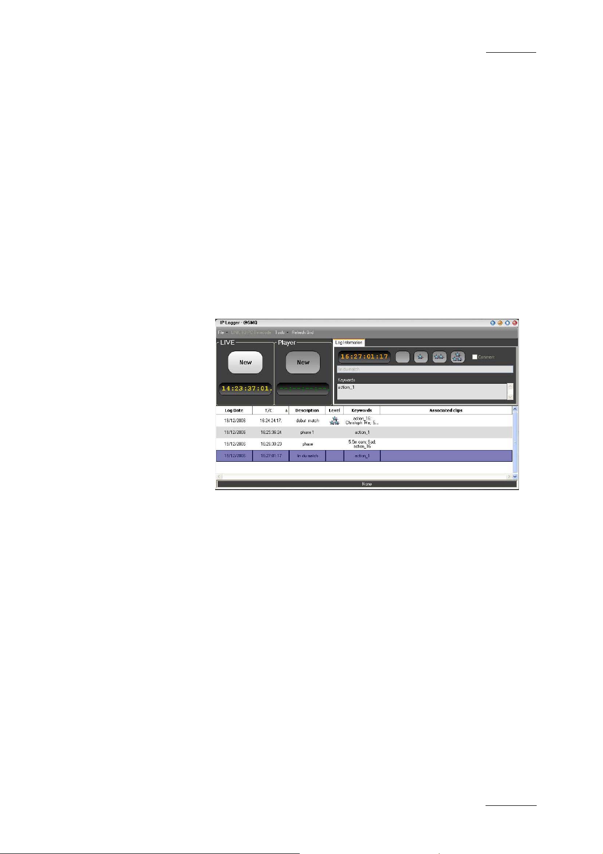
1.1.2 IP LOGGER
A log of recorded material is essen tial to the production process;
by using IP Logger the speed of operations is enhanced by
automatically associating logging data to content on the XNet
network of servers. It can replace the traditional paper log sheet
(which produces manual timecode and descriptions) with a
system that automatically links a logging entry to all relevant
media created on XT servers.
Issue 4.3.C
player channels to play clips sequentially with a
transition either manually or from a play-list.
The IP logger provides an easy way to add descriptive data to
the media and centralize logging data. Using the IP Logger
wizard, a log sheet can be created based on specific production
requirements.
The log sheet is created by capturing the timecode of important
events, and then easily adding keywords using customised
keyword grids, descriptions entered on the keyboard manually,
and a level rating.
Any clip present on the XNet network which includes the
timecode of logged events, and is made from a record train that
has been defined as relevant to the current log entry is then
automatically linked to the corresponding entry in the log sheet.
This effectively links the media on the XNet network to a
workflow that is friendly to a produ cer or editor.
IP Logger also features the capabilities to review and edit
content of the log sheet at any time during or after the event. By
linking a play channel from an XT server, the operator has a
simple and flexible way to refine logging information captured
during the live event.
5
Page 17
Issue 4.3.C
IP Director Version 4.3 – User Manual – Part 1: Introduction
Compared to conventional logging techniques, IP Logger has
significant time-saving benefits, and saving time is always
critical in live production. By producing accurate logs, and
providing an efficient search engine, information is available
faster to all EVS XNet users for browsing, editing and archiving.
Logs can be accessed by other users even while they are being
generated, and XT media associated with the log can be cued
and used instantly.
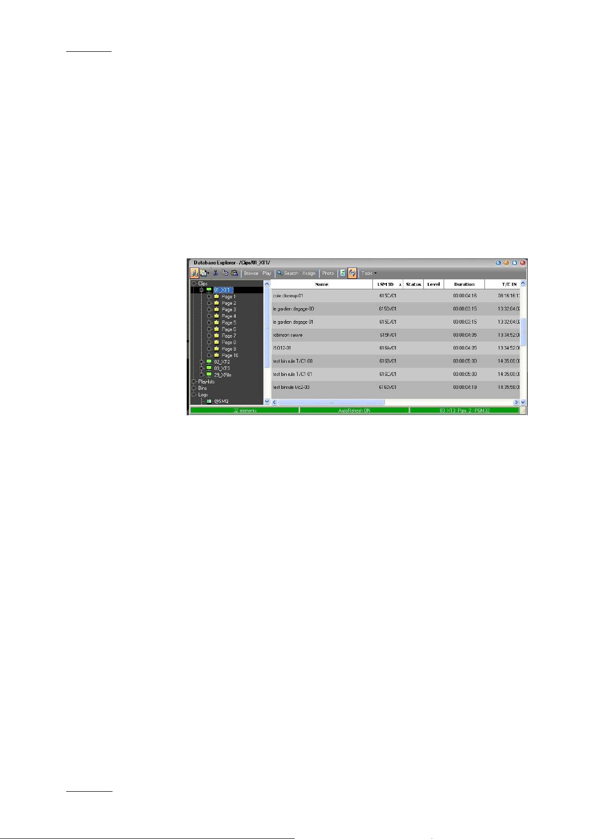
1.1.3 DATABASE EXPLORER
Database Explorer displays and manages clips, play-lists, bins
and logs for the media available on the EVS XNet network.
EVS Broadcast Equipment
Clips & Play-Lists
Clips and Play-Lists created on XT servers are synchronised to
the IP Director central database and can be browsed from this
window.
Bins & Logs
Bins and Logs are details only present on the IP Director
systems, and add improved methods for associating clips and
other details to the user. These sections are not directly visible
on XT servers, but the results of these functions can affect clips
on the XNet network beneficially.
Features of the Database Explorer window include:
• bin management
• log sheet management
• free text search engine and search filters
• keyword filter and assignment
• thumbnail displays
• metadata details (ID , name, timecode, keywords, UmID…)
• fill & key management of clips
6
Page 18
IP Director Version 4.3 – User Manual – Part 1: Introduction
EVS Broadcast Equipment
• browse and playback di rectly from explorer window
• export of log sheets (XML, CSV)
• archive management via XFile
1.1.4 MINI DATABASE EXPLORER
The “Mini Database Explorer” is an integrated part of the Clip
Editor and the Play-List Editor applications used to easily
browse the database content and then use the selected material
in either of the applications without the requirement to have a
full Database Explorer Panel open. It can show all clips, bins
and play-lists that are contained in the database.
1.1.5 RECORDER PANEL
The Record Panel is the graphical user interface used to control
the recorder channels of an XT server. The Recorder Control
Panel shows the record status of a channel and can enable
channels to start or stop recording depending upon the XT server
base configuration. In conjunction with the buttons on the VGA,
there are also keyboard shortcuts and dedicated buttons on the
optional ShuttlePRO controller. Where they are shown, these are
the default settings.
Issue 4.3.C
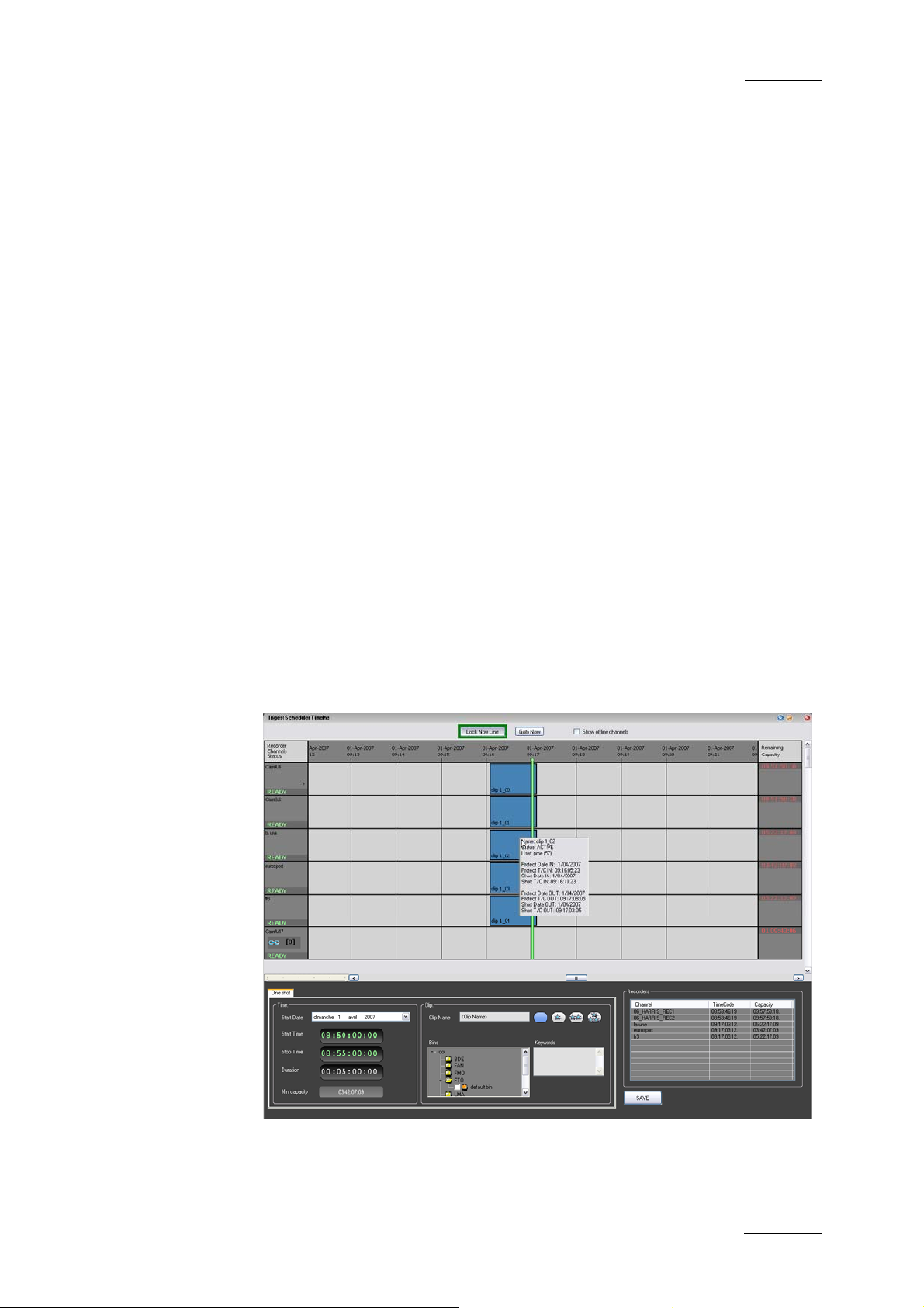
1.1.6 INGEST SCHEDULER
Ingest Scheduler allows for clips to be automatically made from
any record channel under the control of IP Director at either a
time scheduled in advance or entered manually by the user. This
7
Page 19
Issue 4.3.C
IP Director Version 4.3 – User Manual – Part 1: Introduction
means multiple events over a period of time can be automatically
stored. A clip can be created on a channel with a name, level
rating and metadata associat ed with it, and also be automatically
placed into a bin in the Database Explorer.
1.1.7 VTR CONTROL PANEL
The VTR Control Panel allows a VTR (Video Tape Recorder) to
be controlled from IP Director. It is an advanced remote control,
from within the IP Director application.
Apart from playback and record control, it also allows the
extraction of clips from a tape to the XT servers.
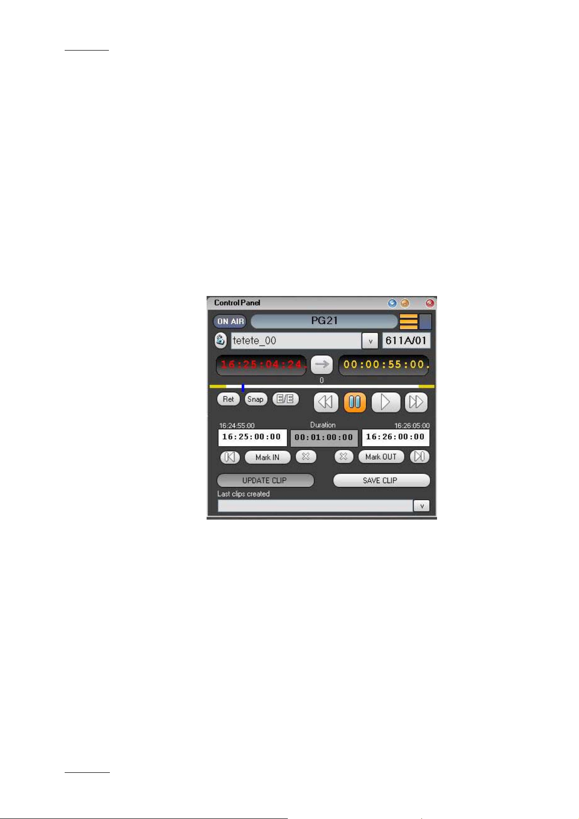
1.1.8 PLAYER CONTROL PANEL
EVS Broadcast Equipment
IP Control Panel is designed to efficiently control XT server
channels with VTR-like functions to clip, trim and playback
media. The Control Panel also has more advanced features such
as the ability to:
• build, edit and play clip lists
• use mix or wipe transitions between linked control panels set
in a Program/Preview mode
• playback in normal, loop, or bounce modes
• synchronize the playback of channels that are ganged
together
• offer parallel control or exclusive control to be passed to
third party devices (control lers, editors, vision mixers…etc).
Within the Control Panel a clip list can be built using a
conventional drag and drop technique from the Database
8
Page 20

IP Director Version 4.3 – User Manual – Part 1: Introduction
EVS Broadcast Equipment
Explorer. Controls for the transition effect, transition duration,
next, and skip are readily accessible and re-ordering, insertion
and deletion of clips can be made even as the list is rolling to air
Using the Control Panel with a Secondary Control function gives
traditional devices such as linear editors the power of instant
access to any material available on the EVS XNet network. Any
media, even while being recorded, can be cued using the Control
Panel and simultaneously controlled by 3rd party editors,
controllers and switchers using industry-standard RS-422
protocols (Sony BVW, Odetics, VDCP, etc…).
1.1.9 PLAY-LIST EDITOR
The Play-List Editor allows multiple play-lists to be made,
modified and played to air using an efficient workflow with a
great deal of flexibility
The workflow combines three work zones within the application
that are needed to perform the task s required:
Issue 4.3.C
• a Mini Database Explorer
• a Play-List interface to manage several play-lists using
different tabs
• a Control Panel (to control a preview channel)
1.1.10 CLIP EDITOR
The clip editor combines
• a Mini Database Explorer
AND
• a Control Panel displayed in full size
It allows the users to search for clips from the Mini Database
Explorer on the left pane and load the clip onto the control panel
on the right pane. The clip can be loaded by drag & drop or
simple mouse click operations.
It is possible to drag and dr op a clip into the control panel of the
clip editor to load it on the corresponding channel. The drag and
drop operation can be performed from the Database Explorer,
Mini Database Explorer , Control Panel and IP Logger.
It is possible to drag and drop a record train from the Clip Tree
View of the Database Explorer, the Mini Database Explorer, from
a bin window or a control panel.
It is possible to drag and drop a play-list from Database
Explorer or the Mini Database Explorer from the Play-List Editor.
9
Page 21

Issue 4.3.C
IP Director Version 4.3 – User Manual – Part 1: Introduction
EVS Broadcast Equipment
1.2 MANAGEMENT AND SYSTEM APPLICATIONS
The IP Director system also has a set of management and
monitoring tools included in the IP Director suite:
1.2.1 KEYWORD MANAGEMENT
A set of applications is used to manage the Keyword database,
prepare grids and dictionaries for logging, searching and
browsing.
Using the Keyword Management tools, a keyword grid’s or
dictionaries content can easily be changed and organised by the
operator and production team to make it perfectly suited for any
sport or live production. An unlimited number of keyword grids,
consisting of up to 300 words each can be managed by IP
Director.
Keyword Management tools allows the addition of single
keywords to the database and therefore to any grid. It also
allows the import of keyword Grids generated by an XT sever,
keyword grids from other IP Director installations and also the
integration of keywords and keyword grids from 3
databases which may already exist such as competitor lists and
team or event statistical databases.
Simple text files can also be easily imported into the Keyword
Database making it easy to import data from a web page or other
document where words exist for your event.
1.2.2 KEYBOARD SHORTCUT DEFINITION
This application is used to define shortcuts that can be used on
the keyboard for each of the production applications in the IP
Director suite
1.2.3 LOGGING ASSOCIATION DEFINITION
When the IP Director suite is opened a check is performed to
establish that all data previously stored in the database still has
associations that are correct and that the media is still available
on the XNet.
rd
party
This application allows the user to manually decide which
aspects of the association between clips and logs should be
initiated afterwards. This window normally is used by an
experienced IP Director operator for very specific purposes.
10
Page 22

IP Director Version 4.3 – User Manual – Part 1: Introduction
EVS Broadcast Equipment
It also allows for a clip to be associated with a log sheet after
importing it from another IP Director workstation.
1.2.4 EVS SYSTEM TOOLS
Within each application there are monitoring tools provided in
the menu structures for the use of EVS engineers to monitoring
the performance of the system and help isolate any support
issues which may arise.
Issue 4.3.C
Note
The Logging Association process takes around 3
minutes for 100 log sheets, each containing 100
elements, so the definition of parameters for this
process only applies to when there is a limited time
available to start the system and a large amount of logs
are stored.
11
Page 23
Issue 4.3.C
IP Director Version 4.3 – User Manual – Part 1: Introduction
2. IP Director
Main Window
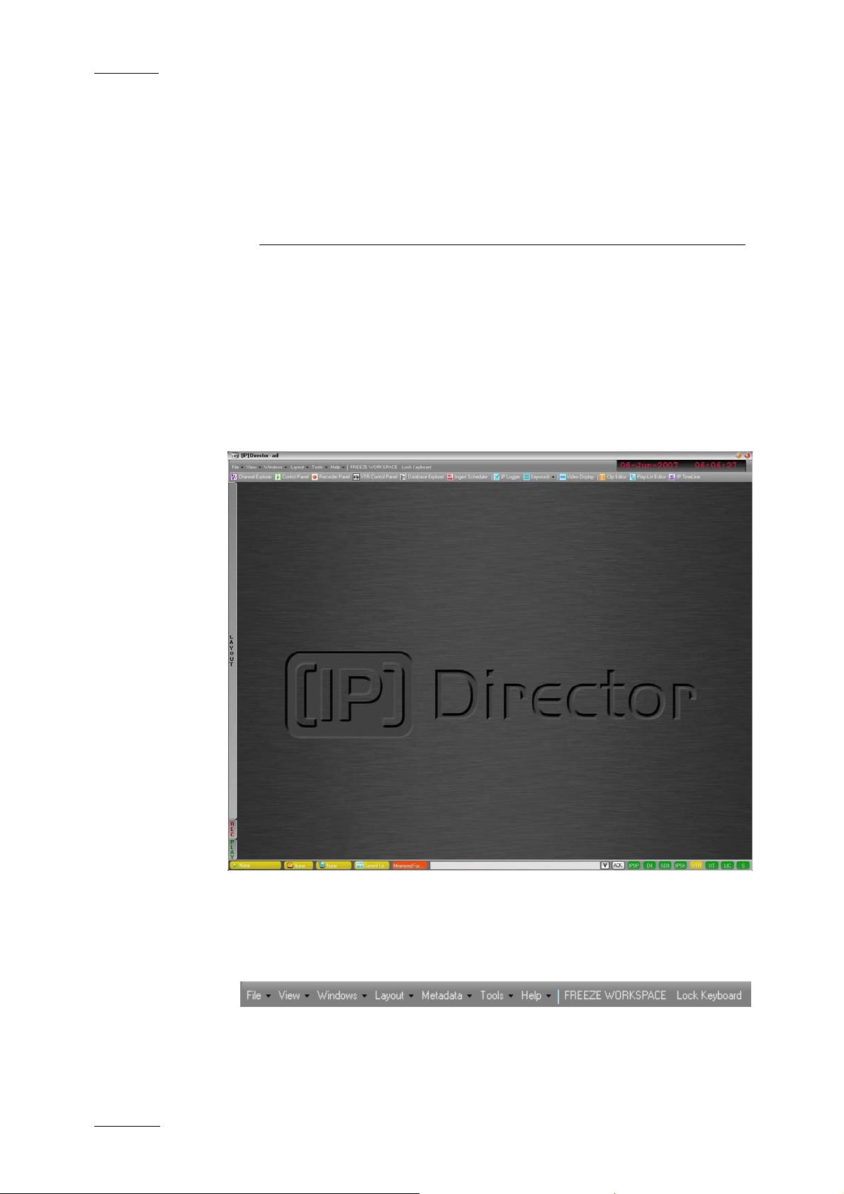
2.1 INTRODUCTION
The IP Director main wi ndow is the window which opens when IP
Director is started. By default the IP Director main window opens
without any application window opened. From this window, the
user can open one or several instances of the various IP Director
applications.
EVS Broadcast Equipment
From the IP Director main window, the user can access the
following elements:
MENU BAR
The menu bar gives acce ss to the following menu commands:
• The File, View, Windows and Layout menu commands, as
well as the Freeze Workspace and Lock Keyboard options
12
Page 24
IP Director Version 4.3 – User Manual – Part 1: Introduction
EVS Broadcast Equipment
allow the users to modify and customize the IP Director user
interface in which they are work ing.
• The Metadata menu gives access to the options for
managing, i.e. importing, exporting and updating, the
customer-defined data that can be associated with clips.
• The Tools menu gives access to the settings defined for the
various IP Director applications as well as some additional
options.
• The Help menu gives access to the user manual, licence
information, etc.
For more information on the menu commands, refer to section
2.2 “Menu Bar”, on page 15.
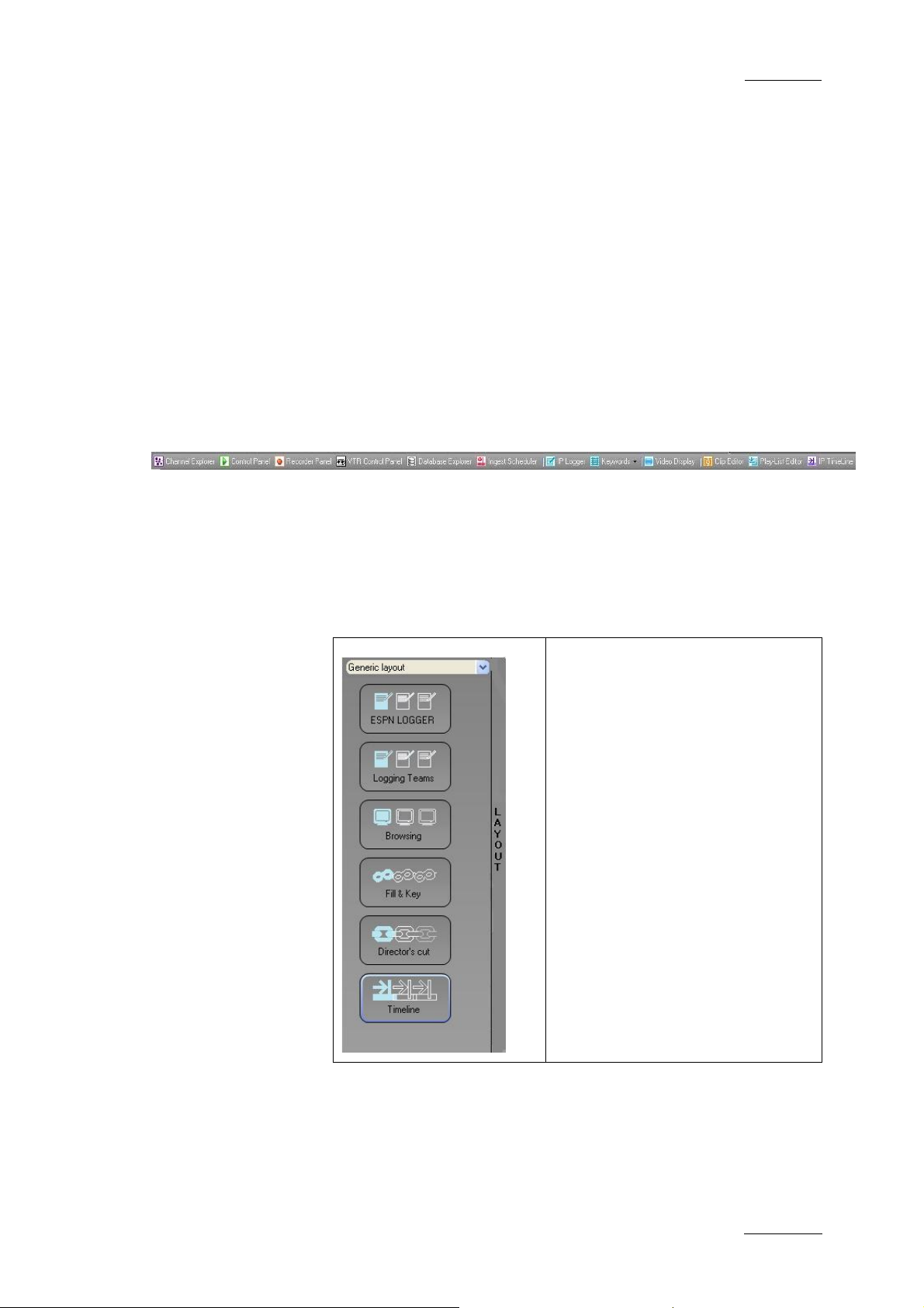
APPLICATION TOOLBAR
The application bar allows the user to access to the IP Director
applications.
Issue 4.3.C
For more information on the application bar, refer to section 2.3
“Application Toolbar”, on page 21.
LAYOUT PANEL
The Layout panel provides a quick
access to defined layout toolbars
and to the layouts included in
these toolbars. It allows the user
to easily load the existing layouts
into their workspace.
For more information on the
Layout tab, refer to section 2.4
“Layout Panel”, on page 22.
13
Page 25

Issue 4.3.C
IP Director Version 4.3 – User Manual – Part 1: Introduction
EVS Broadcast Equipment
CHANNEL STATUS PANEL
The Channel Status panel contains the Recorder Status and
Player Status tabs. They make it possible to view the recorder
and player channels connected to the XNet network, as well as
status information.
For more information on the Channel Status panel, refer to
section 2.5 “Channel Status Panel”, on page 24.
STATUS BAR
The Status bar contains icons that provide information on the
following elements:
• default channel, bin and play-list
• loaded layout icon
• minimised applica tions icon
• message panel
• connection status of IP Director processes and external
components
• license icon
• shortcut icon
In addition, the Status bar gives access to the Copy/Move
Manager via the Message panel.
For more information on the elements available from the Status
bar, refer to section 2.6 “Status Bar”, on page 27.
WORKSPACE
The central area, i.e. the workspace, is used to display the IP
Director applications that the current user opens. Application
windows can be freely resized and organised in the workspace.
14
Page 26

IP Director Version 4.3 – User Manual – Part 1: Introduction
EVS Broadcast Equipment
2.2 MENU BAR
2.2.1 FILE MENU
The File menu includes menu commands to log off and exit IP
Director:
Menu command Description
Log Off User Logs off the current user and displays the
Exit Exits IP Director.
Issue 4.3.C
Log In window.
Note
Prior to log off or exit, the user is invited to save the
current layout. The saved layout will automatically be
displayed the next time the user logs on again to IP
Director.
2.2.2 VIEW MENU
The View menu includes items corresponding to various elements
of the IP Director main window. Each item can be selected to be
displayed or deselected to the hidden on the main window.
Menu command Description
Application Toolbar Displays or hides the Application
Layout Panel Displays or hides the Layout Shortcut
Status Panel Displays or hides the Status bar
toolbar
panel
(excluded the Channel Status panel)
Green Information
on VGA
Message Box Displays or hides the message boxes.
Enables or disables the display of the
green messages on the IP Director
main window when a specific action
has been performed, e.g. CLIP
CREATED, CLIP DELETED…etc.
If the option is not selected, no
message box will be displayed on the
workspace. They will only be added in
15
Page 27

Issue 4.3.C
Menu command Description
2.2.3 WINDOWS MENU
The Windows menu makes it possible to bring to the front or
close the various IP Director applications opened in the current
session.
Menu command Description
Close All Closes all the IP Director applications
IP Director Version 4.3 – User Manual – Part 1: Introduction
the Message panel.
The message boxes are disabled when
robots are used for logging when the IP
Director configuration is tested before
important events.
opened in the current session.
EVS Broadcast Equipment
<Name of open IP
Director
Application>
2.2.4 LAYOUT MENU
The Layout menu is described in details in section 2.8 “Layouts”,
on page 40.
2.2.5 METADATA MENU
The Metadata menu gives access to the options for managing,
i.e. importing, exporting and updating, the metadata on clips.
The Metadata Menu is described in details in section 2.7
“Metadata”, on page 34.
2.2.6 TOOLS MENU
Gives the focus on the application
corresponding to the selected item and
brings it to the front.
The Tools menu gives access to user settings, refresh options
and keyword management for the IP Director user logged on.
SETTINGS
The Setting menu item gives access to a window with eight tabs
to define settings in the following fields:
• general settings
• transport
16
Page 28

IP Director Version 4.3 – User Manual – Part 1: Introduction
EVS Broadcast Equipment
• clip creation
• take effect
• play-list
o default transition
o predefined values for audio swap and effect duration
• GPI and Auxiliary track
Some tabs contain a short description of the settings. However,
you can refer to the sections specified below for more
information on the settings in a tab.
General Settings
The general settings apply to the whole IP Director system.
Display XT Structure
Issue 4.3.C
The Display XT Structure setting ma kes it possible to display the
XT structure in different ways in the various applications where i t
is available, e.g. in the Database Explorer, in the contextual
menu of the Control Panel.
Three possible displays are available:
Display option Description
Do not display All elements are listed without
displaying the XT structure or the page
and bank organisation.
Display XTs but not
Page/Bank
Display XTs, Page
and Bank
All elements are listed on the level
down the XT they belong to.
All elements are listed on the level
down of the page/bank they belong to.
Language
The language setting makes it possible to change the interface
language to the selected language. This is not fully available on
this version.
Key Default Output
The Key Default Output buttons make it possible to define the
forced key channel colour when the user loads a Fill clip that is
not associated with a Key clip:
• A black key channel will be forced if the Black option is
selected.
17
Page 29

Issue 4.3.C
IP Director Version 4.3 – User Manual – Part 1: Introduction
• A white key channel will be forced if the White option is
selected.
EVS Broadcast Equipment
Transport Settings
The Transport settings are applied to all Control Panels on the
workstation; they are not specific to active control panels.
For more information on Transport settings, refer to the Player
Control Panel chapter, in part 3 of the User manual.
Clip Creation Settings
The same remark as for Transport settings is valid for Clip
Creation settings.
For more information on Clip Creation settings, refer to the
Player Control Panel chapter, in part 3 of the User Manual.
Take Effect Settings
The same remark as for Transport settings is valid for Clip
Creation settings.
For more information on Clip Creation settings, refer to the
Player Control Panel chapter, in part 3 of the User Manual.
Play-List Settings (3 tabs)
The Play-List settings are explained in details in the Play-list
Editor chapter, in part 3 of the User Manual.
GPI and Auxiliary Track Settings
The GPI and Auxiliary track settings are explained in details the
Play-list Editor chapter, in part 3 of the User Manual.
LOGGING MANAGER
The Logging Manager provides options to manage the links
between the clips and the log sheet.
18
Page 30

IP Director Version 4.3 – User Manual – Part 1: Introduction
EVS Broadcast Equipment
Refresh all associations between logs and clips
Selecting this option and clicking on start refreshes all links for
all logged events and clips present in the IP Director and XNet
networks
Issue 4.3.C
Refresh the keywords associated with the clip for a log sheet
Selecting this option, choosing a Log Sheet from the list
available and clicking on start refreshes any Keywords that
should be associated with a clip within the specified Log Sheet
Refresh the association between logs and clips for a log sheet
Selecting this option, choosing a Log Sheet from the list
available and clicking on start refreshes any clip associations
between logged events an d clips within the specified Log Sheet
Associate a clip to a log sheet
Selecting this option, choosing a Log Sheet from the list
available and then a clip enables an association to be made if
the clip date and timecode properties appear within the selected
Log Sheet.
Delete a logging profile
Selecting this option, choosing a Logging profile from the list
available and clicking on the ‘Delete’ button deletes the logging
profile from the database. Only logging profiles which are not
currently used in a log sheet can be deleted.
19
Page 31

Issue 4.3.C
IP Director Version 4.3 – User Manual – Part 1: Introduction
EVS Broadcast Equipment
RECREATE ALL THUMBNAILS
This setting enables the creation of thumbnails from a particular
XT when there is an XFile in the XNet network set to create
thumbnails. Normally this process will function as a b
process. If a system needs to have its clips thumbnails recreated,
this window allows a manually initiation of that process.
The Recreate button will send XML files to the XFile on the network
that will create thumbna
ils for the IP Director system.
ackground
DEFINE SHORTCUTS
The Shortcut definition is explained in details in the System
Management chapter, in part 4 of the Us er Manual.
ALL CLIPS STATUS AND HIST ORY
Selecting this menu item will display the Status and History
window for all clips. This window provides detailed information
on the clip transfers that have been performed, whether they
succeeded or not.
OWN CLIPS STATUS AND HISTORY
Selecting this menu item will display the Status and History
window for the clips that the current user created. This window
provides detailed information on the clip transfers that have
been performed, whether they succeeded or not.
TRANSFER INFORMATION
Selecting this menu item will display the Transfer Information
window that provides inform ation on the pending clip transfers.
The following information is displayed on the window:
• clip name
• estimated transfer duration
• transfer type
The window displays additional information on the number of
clips that the logged on user has already created and the
maximum number of clips that this us er can create.
20
Page 32

IP Director Version 4.3 – User Manual – Part 1: Introduction
EVS Broadcast Equipment
For more information on the Transfer Information window, refer
to the Database Explorer chapter, in part 2 of this User Manual.
CHANGE PASSWORD
This setting allows the currently logged on user to change their
password.
2.2.7 HELP MENU
The Help menu from the Main Toolbar gives access to version
and License checking features, together with Monitoring
applications for the use of EVS Staff.
The OSD settings refers to the on-screen display when using the
ShuttlePRO controller and also gives a message when a clip has
been created.
Issue 4.3.C
2.2.8 FREEZE WORKSPACE
Selecting this option on the menu bar locks the IP Director
workspace to prevent from moving windows, resizing windows or
opening a new IP Director application. The option is selected
again to unfreeze the workspace.
The option on the menu bar changes to Red as a warning of this
action. The operator can still open the layout shortcut panel and
click a shortcut to c hange the layout.
2.2.9 LOCK KEYBOARD
Selecting this option on the menu bar locks the Keyboard from
use on the workstation. The option is selected again to unlock
the keyboard.
The option on the menu bar changes to Red as a warning of this
action. The control of the workstation is still possible with a
mouse or touch screen.
2.3 APPLICATION TOOLBAR
The application toolbar provides direct access to the various IP
Director applications. When the user clicks the icon
corresponding to a given application, the application opens in
the workspace.
For the Keyword Management application, the user needs to
select in the sub-menu whether to open the Keyword grid,
dictionary, list or the three of them.
21
Page 33
Issue 4.3.C
IP Director Version 4.3 – User Manual – Part 1: Introduction
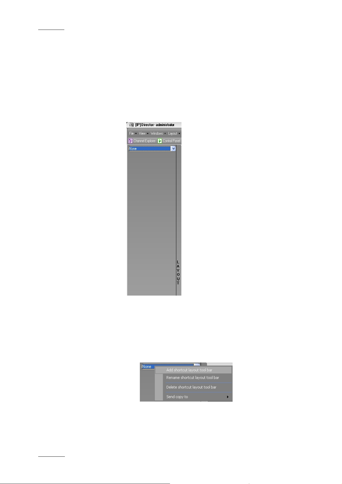
2.4 LAYOUT PANEL
2.4.1 INTRODUCTION
The Layout panel allows single-click access to your saved
Layouts.
It opens when you click the Layout tab on the left screen border.
The Layout panel is empty when you
first open it.
Several Layout toolbars can be defined
and loaded from the drop-down list box
at the top of the Layout panel.
Each toolbar can contain a number of
layouts. These layouts are called from
the shortcuts displayed in the Layout
panel.
EVS Broadcast Equipment
The procedures for creating Layout
toolbars and adding items to the
toolbars are explained in detail below.
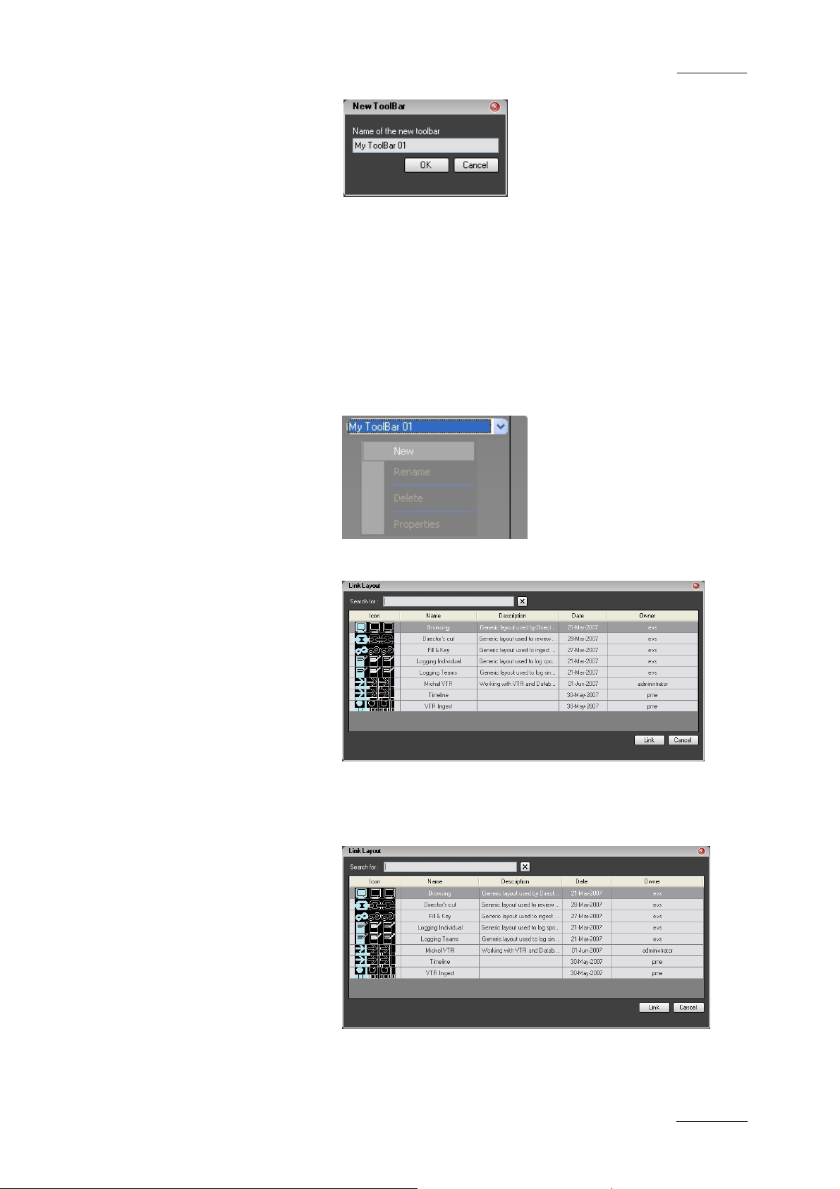
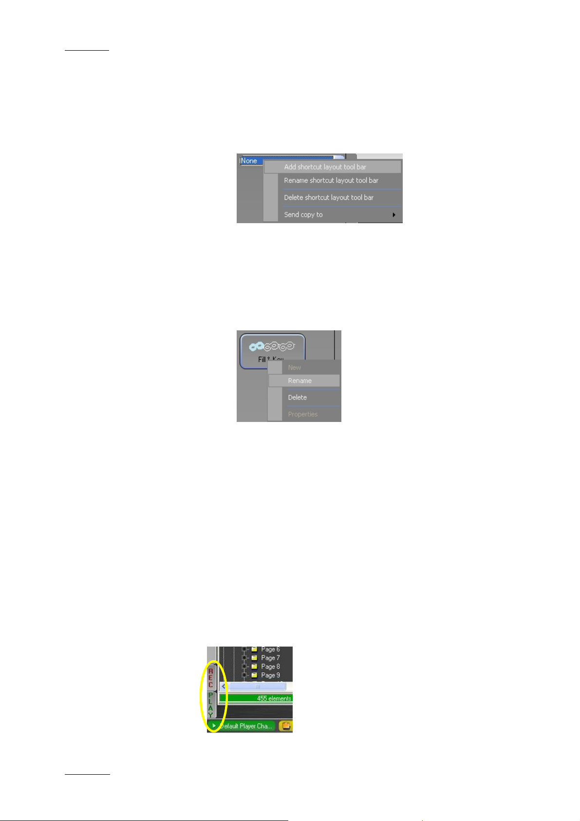
2.4.2 HOW TO CREATE A LAYOUT TOOLBAR
To create a Layout toolbar, proceed as follows:
1. Right-click the blue drop-down combo box and select Add
shortcut layout toolbar.
2. Enter a name for the new toolbar:
22
Page 34
IP Director Version 4.3 – User Manual – Part 1: Introduction
EVS Broadcast Equipment
2.4.3 HOW TO ADD A LAYOUT TO A LAYOUT TOOLBAR
To add a Layout to a Layout toolbar, pr oceed as follows:
1. Right-click the grey empty region under the blue drop-
Issue 4.3.C
and click OK.
down combo box and select New.
2. S elect a Layout from the Link Layout window:
and click Link.
3. If required, repeat steps 1 and 2 to add more Layouts to
the toolbar.
23
Page 35
Issue 4.3.C
IP Director Version 4.3 – User Manual – Part 1: Introduction
2.4.4 OTHER LAYOUT TOOLBAR COMMANDS
To perform other Layout toolbar operations, more commands are
available:
1. Right-click the blue drop-down combo box:
2. Select one of the commands to:
• rename a shortcut layout toolbar
• delete a shortcut layout toolbar
• send a copy to another user
3. Right-click a button in the layout toolbar:
EVS Broadcast Equipment
4. Select one of the commands to:
• rename a button
• delete a button
2.5 CHANNEL STATUS PANEL
The Channel Status panel is made up of the Recorder Status
panel and the Player Status panel. These panels allow the user
to monitor the statuses of request ed recorder or player channels.
By default, the panels are minimised to small REC and PLAY
tabs on the bottom left side of the workspace as shown in the
screenshot below.
24
Page 36
IP Director Version 4.3 – User Manual – Part 1: Introduction
EVS Broadcast Equipment
OPENING AND CLOSING THE CHANNEL STATUS PANELS
To open the Recorder Status panel or Player Status panel for the
first time in a session, right-click the tab and select the View
Recorder/Player Panel opt ion.
To open Recorder Status panel or Player Status panel again in
the session, simply clic k the REC or PLAY tab.
To close the Recorder Status panel or Player Status panel, click
again on the REC or PLAY tab.
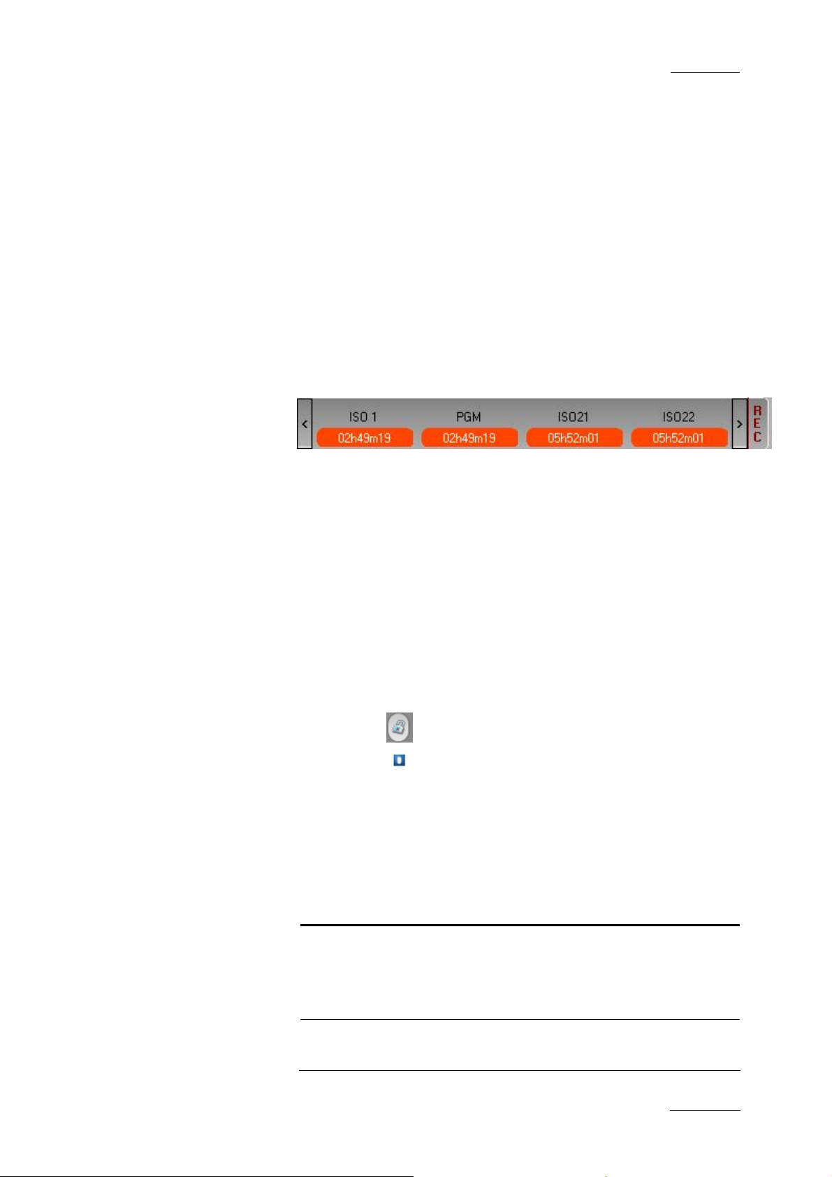
2.5.1 RECORDER STATUS PANEL
Issue 4.3.C
DISPLAYED STATUS INFORMATION
The Recorder Status panel provides the following status
information on the recorder displayed on the panel:
• recorder channel name
• remaining capacity on the recorder
• recording status
o capacity information on a red background if the channel
is recording
o capacity information on a green background if the
channel is not recording
• lock icon
• gang icon
if the channel is locked
if the channel is ganged
POSSIBLE ACTIONS
From the contextual menus available in this panel, you can
perform the following actions:
Contextual menu
item
View Recorder
Panel
Add or Remove
Recorders
Description
Displays or minimizes the recorder
panel.
This menu item is available when rightclicking on the panel edges.
Allows the user to add recorders to or
remove recorders from the Recorder
25
Page 37

Issue 4.3.C
IP Director Version 4.3 – User Manual – Part 1: Introduction
EVS Broadcast Equipment
Contextual menu
item
View All Recorders Displays all recorder channels
Remove Removes a given recorder from the
Description
panel.
This menu item is available when right-
clicking on the panel edges.
Selecting this item opens the Define
the Recorder Channels window from
where you can select the recorders to
be added to or removed from the
Recorder panel.
available on the XNet network.
This menu item is available when right-
clicking on the panel edges.
recorder panel.
This menu item is available when right-
clicking on the data related to a given
recorder.
2.5.2 PLAYER STATUS PANEL
DISPLAYED STATUS INFORMATION
The Player Status panel provides the following status information
on the players displayed on the panel:
• player channel name
• player status
o on Air red button if the player channel is on air
o off Air grey button if the player channel is off air
• lock icon if the channel is locked
• gang icons
POSSIBLE ACTIONS
if the channel is ganged
From the contextual menus available in this panel, you can
perform the following actions:
26
Page 38

IP Director Version 4.3 – User Manual – Part 1: Introduction
EVS Broadcast Equipment
Issue 4.3.C
Contextual menu
Description
item
View Players Displays or minimizes the player panel.
This menu item is available when rightclicking on the panel edges.
Add or Remove
Players
Allows the user to add players to or
remove players from the Player pa nel.
This menu item is available when rightclicking on the panel edges.
Selecting this item opens the Define
the Player Channels window from
where you can select the players to be
added to or removed from the Player
panel.
View All Players Displays all player channels available
on the XNet network.
This menu item is available when right-
clicking on the panel edges.
Remove Removes a given player from the
Player panel.
This menu item is available when right-
clicking on the data related to a given
player.
2.6 STATUS BAR
The Status bar contains icons that provide information on the
following elements:
• default channel, bin and play-list
• loaded layout icon
• minimised applica tions icon
• message panel
• connection status of IP Director processes and external
components
• license icon
• shortcut icon
In addition, the Status bar gives access to the Copy/Move
Manager via the Message panel.
The following elements in the status bar are explained in the
sections below.
27
Page 39

Issue 4.3.C
2.6.1 DEFAULT ICONS
The default icons info rm whether a default player channel, bin or
play-list has been defined. If this is the case, the name of the
default channel, bin or play-li st will be displayed.
DEFAULT CHANNEL ICON
If a default channel has been defined, the Default Channel icon
displays the name of t he default channel on a green ba ckground.
If no default channel is defined, the ‘None’ value will be
displayed on a yellow background.
The icon is for informative purpo se.
You can define a default channel in the Channel Explorer, via
the Set as Default Player option available from the contextual
menu.
IP Director Version 4.3 – User Manual – Part 1: Introduction
EVS Broadcast Equipment
You can clear the default by double-clicking the Default Channel
icon.
DEFAULT BIN ICON
If a default bin has been defined, the Default Bin icon displays
the name of the default bin on a green background.
If no default bin is defined, the ‘None’ value will be displayed on
a yellow background.
The icon is for informative purpose. However, the option to send
an element to the default bin is available from the contextual
menu of the various applications when this is relevant.
You can define a default bin in the Database Explorer, via the
Set as Default Bin option available from the contextual menu.
You can clear the default by double-clicking the Default Bin icon.
DEFAULT PLAY-LIST ICON
If a default play-list has been defined, the Default Pay-List icon
displays the name of the default pl ay-list on a green background.
If no default play-list is defined, the ‘None’ value will be
displayed on a yellow background.
28
Page 40
IP Director Version 4.3 – User Manual – Part 1: Introduction
EVS Broadcast Equipment
The icon is for informative purpose. However, the option to send
an element to the default play-list is available from the
contextual menu of the various applications when this is
relevant.
You can define a default play-list in the Database Explorer, via
the Set as Default Play-List option available from the contextual
menu.
You can clear the default by double-clicking the Default Play-List
icon.
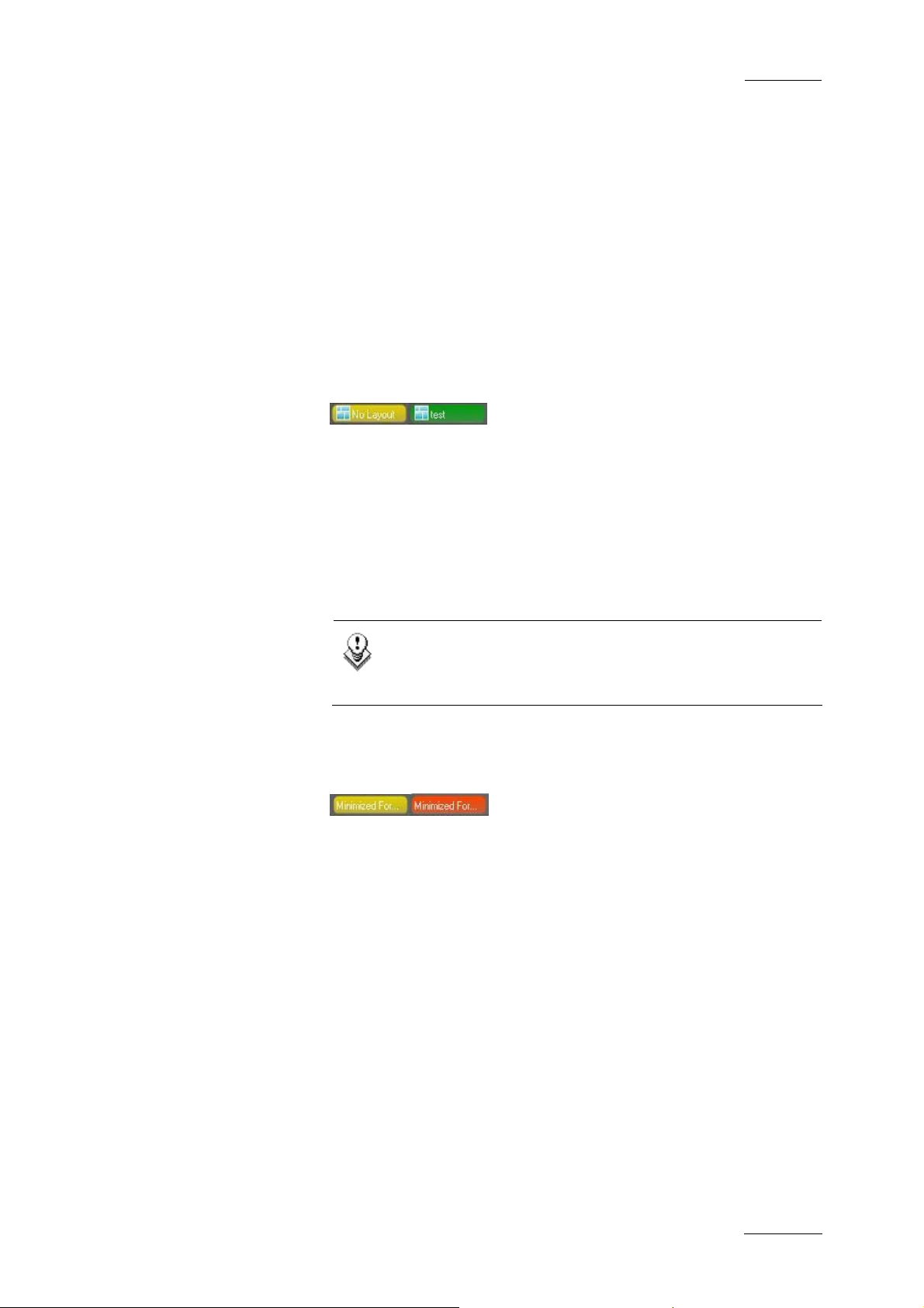
2.6.2 LOADED LAYOUT ICON
The Loaded Layout icon displays the name of the layout that is
currently loaded in IP Director on a green background.
The Loaded Layout icon displays the ‘No Layout’ value on a
yellow background when no layout is currently loaded in IP
Director.
Issue 4.3.C
You can clear the layout by double-clicking the Loaded Layout
icon.
Note
Clearing the current layout will clear the entire user
interface of all open windows! Use this with caution .
2.6.3 MINIMISED ICON
The Minimised icon tells the user whether windows are minimised
and allows the user to restore the minimised windows.
When no window is minimised, the Minimised icon will have a
yellow background.
When one or more windows are minimised, the Minimised icon
will have a red backgr ound.
To restore a minimised window, click the Minimize button and
select the minimised display of the window you want to restore.
29
Page 41

Issue 4.3.C
2.6.4 MESSAGE PANEL
The message panel provides a quick display of the information,
warning and error messages generated in the current session. It
is minimised by default in a message field which displays only
the most recent message in the Stat us bar.
ACCESSING AND CLOSING THE MESSAGE PANEL
You will open the Message panel by clicking the V sign on the
right of the Message bar.
The Message panel is minimised back to the Message field when
you click outside the panel or click the V sign again.
IP Director Version 4.3 – User Manual – Part 1: Introduction
EVS Broadcast Equipment
INFORMATION AVAILABLE IN THE MESSAGE BAR
The messages include the followi ng information:
• the date and time when the message was generated
• the message itsel f
• the type of message
MESSAGE COLOUR
The messages are highlighted in a different colour depending on
the type of message:
• An information message is highlighted in green.
• A warning message is highlighted in yellow.
• An error message is highlighted in red.
• The selected message has a darker background than the
normal background.
MESSAGE FILTER
The user can perform a filter on the message type by clicking the
message type icons displayed on the top left corner of the
expanded Message bar:
• When the message type icon has a pink background, the
messages that belong to that typ e are displayed, if any.
• When the message type icon has a blue background, the
messages that belong to that type are not displayed.
30
Page 42

IP Director Version 4.3 – User Manual – Part 1: Introduction
EVS Broadcast Equipment
2.6.5 COPY/MOVE STATUS PANEL
The Copy/Move Status panel provides information on the clips
that are being or have been copied or moved to another location.
It will only display the moves or copies to another XT server than
the one where the cli p was initially stored.
ACCESSING AND CLOSING THE COPY/MOVE STATUS PANEL
You will access the Copy/Move Status panel via the Message
panel, by selecting Copy/Move Status from the drop-down list on
the top right corner of the Message panel, as shown in the
screenshot below.
Issue 4.3.C
The Copy/Move Status panel will remain open even when you
click outside the panel. To close the Copy/Move Status panel,
double-click the V sig n on the right of the Message bar.
COPY/MOVE COMMANDS
To copy, i.e. duplicate or move clips to another location on the
same or another XT server, you ne ed to use the Duplicate / Copy
options available from the contextual menu in the Database
Explorer or the Mini Database Explorer. The Copy/Move Status
panel is for informative purpos e only.
For more information on the Copy/Move function, refer to the
section “How to Copy or Move a Clip within the Database
Explorer”, in the Database Explorer chapter, in part 2 of this
User Manual.
COPY/MOVE STATUS DISPLAYS
The Copy/Move Status panel provides different displays that the
user can select in the upper right corner of the panel:
31
Page 43

Issue 4.3.C
IP Director Version 4.3 – User Manual – Part 1: Introduction
EVS Broadcast Equipment
Display Type Description
My Copy/Move Displays the clips that the current user
is duplicating or moving to another XT
server.
It provides a progress bar to monitor
the copy/move operation.
All Copy/Move Displays the clips that all logged on
users are duplicating or moving to
another XT server.
It provides a progress bar on each clip
to monitor the copy/move operation.
My History Displays the clips that the current user
has duplicated or moved to another XT
server in the current session.
All History Displays the clips that all logged on
users have duplicated or moved to
another XT server in the current
session.
Note
The All Copy/Move and All History displays will display
the clips to which the user has visibility rights.
INFORMATION IN COPY/MOVE AND HISTORY DISPLAYS
The following information is available in the Copy/Move and
History displays:
• clip name
• initial clip locatio n
• action type, i.e. copy or move
• final clip location
• progress bar indicating how many percents of the move or
copy has been performed
• date and time when the copy/move started
• date and time w hen the copy/move ended
32
Page 44

IP Director Version 4.3 – User Manual – Part 1: Introduction
EVS Broadcast Equipment
• process status: “in progress” or “finished”
• user who performed the copy/move.
ACKNOWLEDGE BUTTON
When the users have read a message, they can acknowledge it
by clicking the ACK button. The Acknowledge button changes the
background of the selected message to grey. This helps the user
distinguish the messages that have been dealt with from the
ones that have not.
2.6.6 PROCESS STATUS ICONS
The background colour of the Status icons provides information
on the status of the processes that run in the background:
Issue 4.3.C
• When the background colour is green, the process is running
or the connection is established.
• When the background colour is yellow, the process is not
running or the connection is not established.
For more information on these processes, refer to the Technical
Reference manual.
Icon Description
IPDP Status icon for the IP Director Routing process
DB Status icon for the database connection
SDB Status icon for the SynchroDB pro cess
IPSH Status icon for the IP Scheduler process
VTR Status icon for the VTR Engine process
XT Status icon for the XT connection
33
Page 45

Issue 4.3.C
2.6.7 LICENCE ICON
The background colour of the License icon turns yellow when one
of the IP Director licen ses is expiring within two weeks .
2.6.8 SHORTCUTS ICON
The background colour of the Shortcut icon turns yellow when
the Shortcut function is deactivated. Double-clicking the icon will
reactivate the shortcut function in IP Director. For technical
reasons, the Shortcut function is deactivated when the user edits
a text field.
IP Director Version 4.3 – User Manual – Part 1: Introduction
EVS Broadcast Equipment
2.7 METADATA
2.7.1 METADATA, PROFILES AND FIELDS
Metadata is customer-defined data which can be associated with
clips in IP Director.
The metadata is available in IP Director via profiles, i.e. sets of
fields which are managed together. Lists of possible values are
provided with each of the fields in the form of the drop-down
lists. Other fields are text fields in which the user types a value.
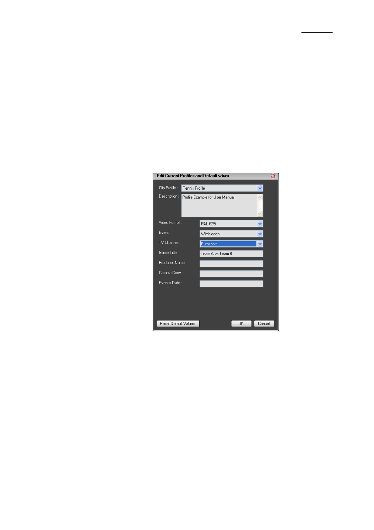
The user can also specify a default value for a field.
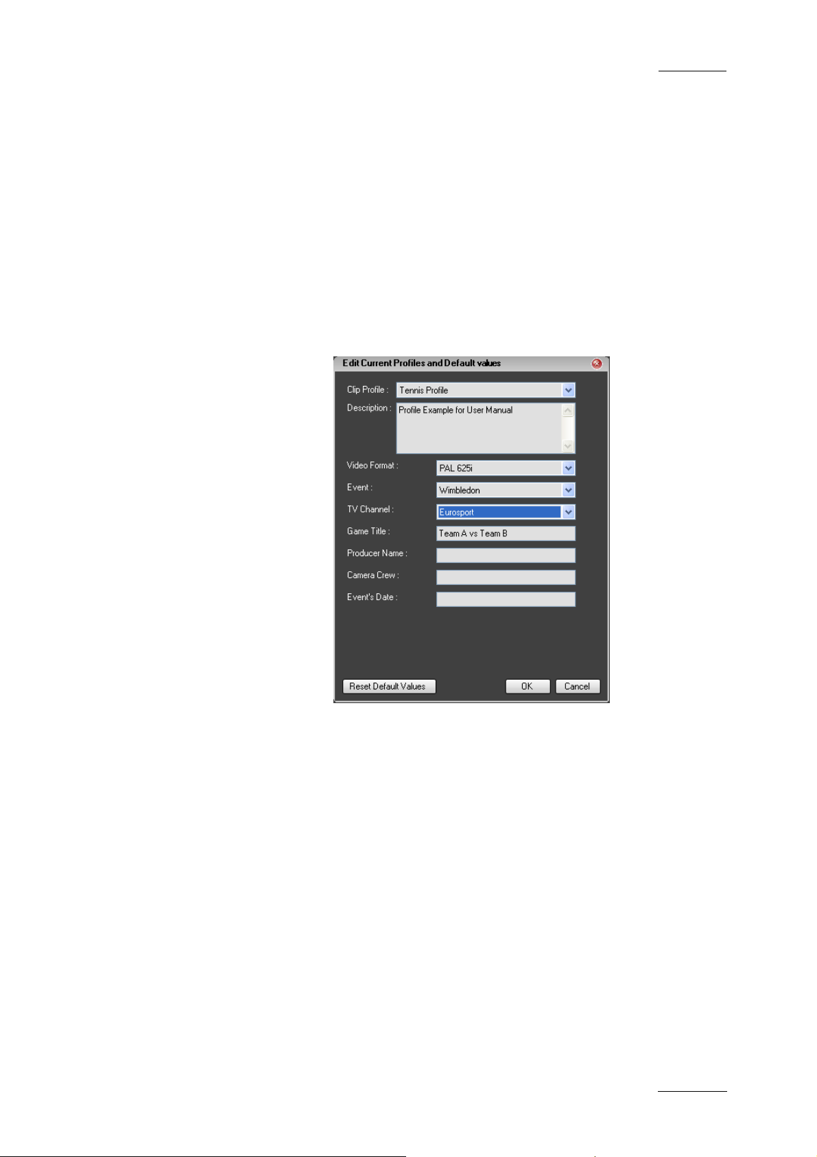
These metadata profiles and related fields are defined in
dedicated .xml files which can be imported into IP Director. The
following screenshot shows an example of a profile for a tennis
event.
34
Page 46

IP Director Version 4.3 – User Manual – Part 1: Introduction
EVS Broadcast Equipment
Issue 4.3.C
Once a profile has been imported in IP director, its related
metadata can be associated with clips loaded in the Control
Panel or in the Database Explorer. Later on, it can be used in
searches for clips.
For more information on how to use the metadata in the IP
Director applications, refer to the following chapters and
sections:
• Control Panel chapter: sections “Metadata tab” and “How to
Add or Modify Metadata of a Clip”.
• Database Explorer chapter: section “Edit Clip Window”
2.7.2 CURRENT PROFILE
Only one metadata profile at a time can be defined as the
current profile in IP Director.
The fields of the current profile and the possible default values
for these fields will be applied by default to the new clips when
they are saved.
35
Page 47

Issue 4.3.C
2.7.3 METADATA MENU
The following menu items are available from the Metadata menu,
in the menu bar of the main IP Director window.
Menu command Description
IP Director Version 4.3 – User Manual – Part 1: Introduction
EVS Broadcast Equipment
Edit Current Default
Metadata
Opens the Edit Current Profiles and
Default Values window from which you
can perform the foll owing actions:
• change the current profile applied
by default to new clips
• modify the default values in the
current profile or in any other
profile available in IP Director.
For more information on how to
perform these actions, refer to the
sections below.
Import Profile Opens the Import a Profile window from
which you can select the metadata .xml
file to import into IP Director.
Export Profile Opens the Choose Clip Profile window
from which you can select the profile to
export into an .xml file.
36
Page 48
IP Director Version 4.3 – User Manual – Part 1: Introduction
EVS Broadcast Equipment
2.7.4 HOW TO CHANGE THE CURRENT PROFILE
You can change the current metadata profile, i.e. the profile that
will be associated by default to the new clips when they are
saved.
To change the current profile , proceed as follows:
1. In the main IP Director window, select the menu Metadata
Issue 4.3.C
> Edit Current Default Metadata.
The Edit Current Profile and Default Values window
opens:
2. In the Clip Profile field, select the profile to be used as
current profile.
All the fields of the profile are displayed below the Clip
Profile field.
3. Click OK.
The new current profile is loaded and will now be associated by
default to all new created clips.
37
Page 49

Issue 4.3.C
IP Director Version 4.3 – User Manual – Part 1: Introduction
EVS Broadcast Equipment
2.7.5 HOW TO MODIFY THE DEFAULT VALUES OF A PROFILE
When a metadata profile is imported into IP Director, the default
values specified in the .xml file are imported. It is possible to
modify the default values of a prof ile.
To modify the default values of a profile, proceed as follows
1. In the main IP Director window, select the menu Metadata
> Edit Current Default Metadata.
The Edit Current Profile and Default Values window
opens:
38
2. In the Clip Profile field, select the profile to be managed.
All the fields of the profile are displayed below the Clip
Profile field.
3. Select or enter the desired default values in the profile
fields.
4. Click OK.
The new specified values will now be used as default values for
the new created clips.
Page 50
IP Director Version 4.3 – User Manual – Part 1: Introduction
EVS Broadcast Equipment
2.7.6 HOW TO RESET THE DEFAULT VALUES IN A PROFILE
If you have modified the default values of a metadata profile in
IP Director, you can reset the initial default values at any time,
as they were defined when the .xml file was im ported.
To reset the default values of a pr ofile, proceed as follows
1. In the main IP Director window, select the menu Metadata
Issue 4.3.C
> Edit Current Default Metadata.
The Edit Current Profile and Default Values window
opens:
2. In the Clip Profile field, select the profile to be managed.
All the fields of the profile are displayed below the Clip
Profile field.
3. Select the Reset Default Values button on the bottom left
part of the window.
4. Click OK.
The default values have been reset to the initial ones.
39
Page 51

Issue 4.3.C
2.8 LAYOUTS
2.8.1 OVERVIEW
Depending on job content and personal preferences, most users
have a preferred screen layout (open windows and window
positions).
The purpose of the Layout features in IP Director is to present a
user his personalised screen layout every time he logs on to IP
Director.
A number of Layout definitions can be saved and retrieved with a
single mouse click.
Through the Layout menu, the user can create, save, open and
publish a layout.
The Layout Toolbar allows one-click access to saved layouts.
IP Director Version 4.3 – User Manual – Part 1: Introduction
EVS Broadcast Equipment
2.8.2 LAYOUT MENU
The Layout menu contains the following options:
• New: create a new Layout
• Open: open an existing Layo ut
• Save Layout: save the current La yout
• Save current layout as: save the current Layout with a new
name
• Delete: delete an existing Layout
• Publish: publish a Layout to a user group
• Properties: view or change the Layout properties
These features are explaine d in detail below.
40
Page 52
IP Director Version 4.3 – User Manual – Part 1: Introduction
EVS Broadcast Equipment
HOW TO CREATE A NEW LAYOUT
To create a new Layout, proceed as follows:
1
2
Issue 4.3.C
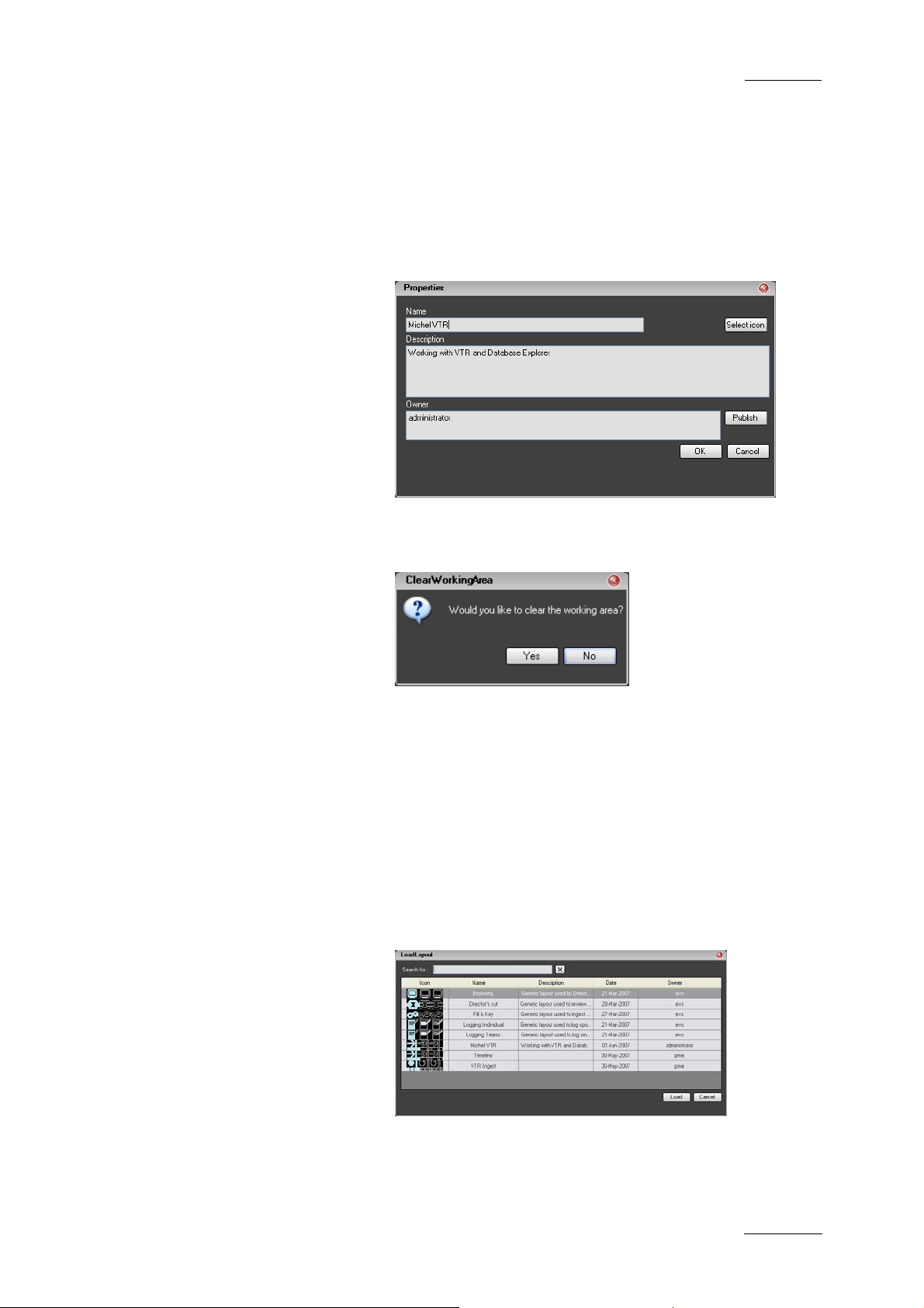
Click Layout > New
Enter the appropriate information in the Properties
window that appears:
and click OK.
The following option window appears:
3
Click Yes if you want to start from a clean working area
or No if you want to create a new Layout based on your
current working area.
HOW TO OPEN AN EXISTING LAYOUT
To open an existing La yout, proceed as follows:
Click Layout > Open
1
Select a Layout in the Load Layout window and click
2
Load.
41
Page 53

Issue 4.3.C
IP Director Version 4.3 – User Manual – Part 1: Introduction
EVS Broadcast Equipment
HOW TO SAVE A LAYOUT
To save the current Layout, proceed as follows:
Click Layout > Save
1
The current work area is saved with the current Layout
2
name.
HOW TO SAVE A LAYOUT WITH A NEW NAME
To save the current Layout with a new name, proceed as follows:
Click Layout > Save current layout as
1
Enter the appropriate information in the Save Current
2
Layout As window that appear s:
and click OK.
HOW TO DELETE AN EXISTING LAYOUT
To delete an existing Layout, proceed as follows:
Click Layout > Delete
1
Select the Layout you wish to delete:
2
and click Delete.
42
Page 54
IP Director Version 4.3 – User Manual – Part 1: Introduction
EVS Broadcast Equipment
HOW TO PUBLISH A LAYOUT
To publish a Layout, proceed as fol lows:
1
2
Issue 4.3.C
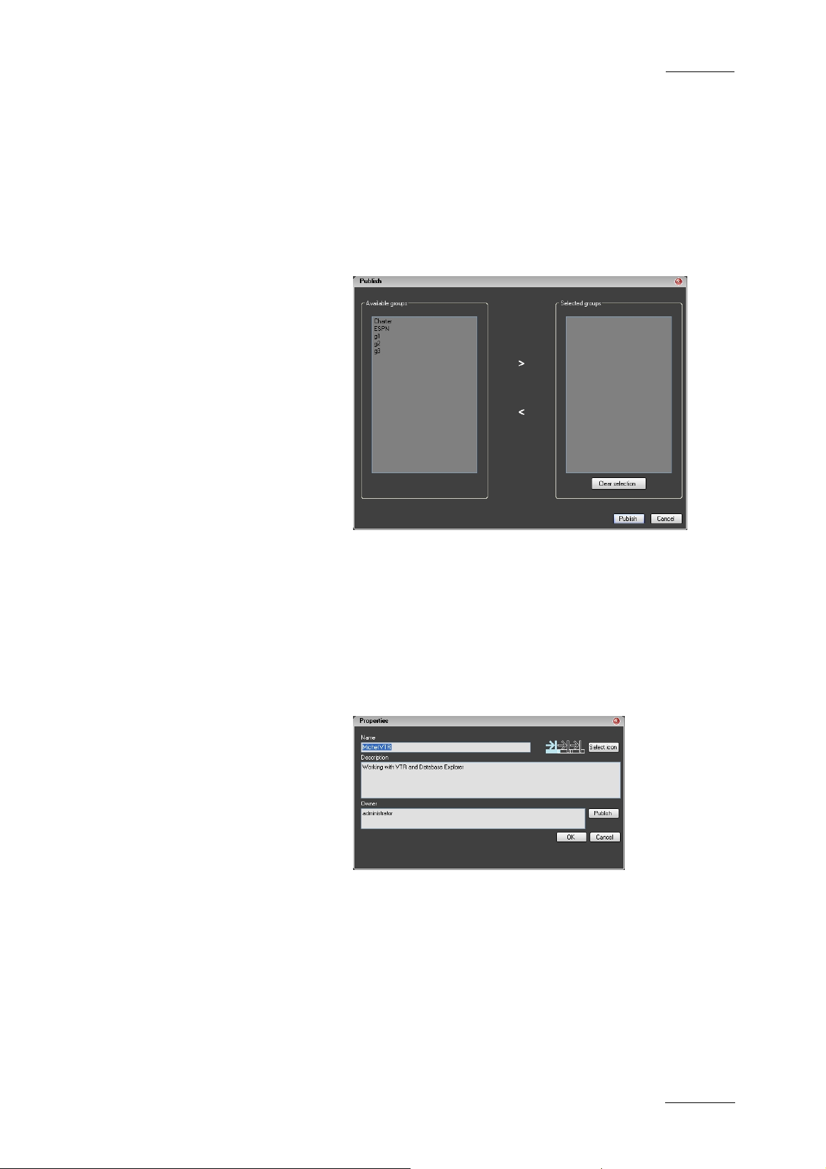
Click Layout > Publish
Select the user groups to which you wish to publish
your current Layout and click the > button to move the
group from Available groups to Selected groups.
and click Publish.
HOW TO VIEW OR CHANGE LAYOUT PROPERTIES
To view or change the Layout Prope rties, proceed as follows:
Click Layout > Properties
1
Make any required changes in the Properties window:
2
and click OK.
43
Page 55
Issue 4.3.C
IP Director Version 4.3 – User Manual – Part 1: Introduction
3. Channel Explorer
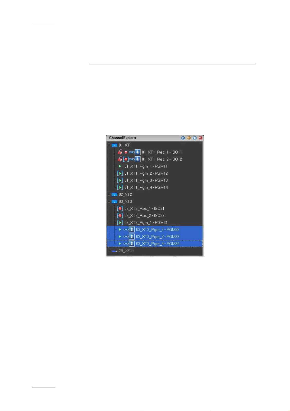
3.1 INTRODUCTION
Channel Explorer gives a comprehensive overview of all XT
servers with their respective channel configurations (number of
inputs and outputs). It also shows any XFile and XStore devices
on the XNet SDTI network, and VTRs being controlled by an IP
Director workstation.
EVS Broadcast Equipment
44
.
From within the Channel Explorer application any IP Director
workstation can take control of one or several channels from
different XT servers connected on the XNet. When control has
been taken the selected channels can then be locked.
The flexibility of IP Director allows multiple channels to be
ganged together, either for simple ganged playback of several
different sources, or specialised playback modes such as Key
and Fill and a Program/Preview mode to play clips sequentially
with a transition either manually or from a play-list.
These multiple playback modes can be used both on clips or
play-lists to offer a comprehensive range of operational playback
modes using a conventional computer interface with Keyboard,
mouse, and VGA which is familiar to any computer user.
Page 56
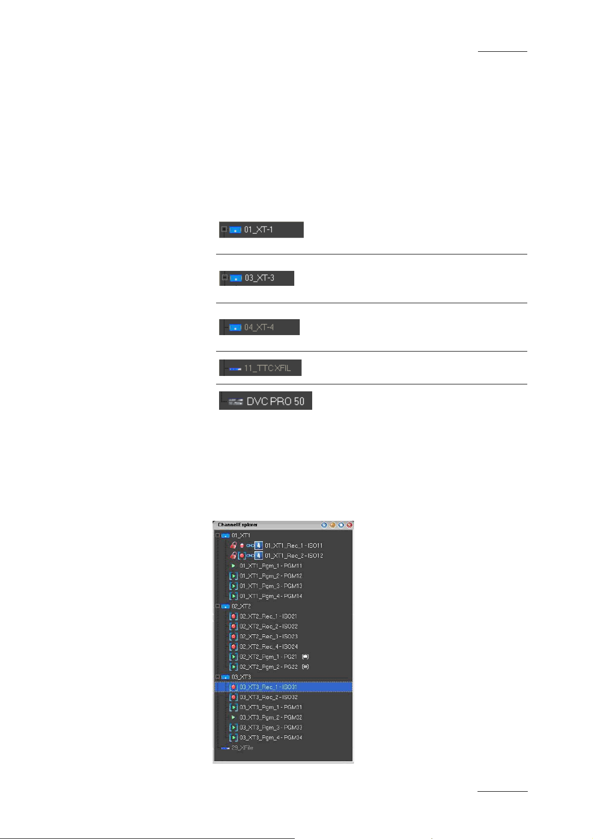
IP Director Version 4.3 – User Manual – Part 1: Introduction
EVS Broadcast Equipment
3.2 STATUS DISPLAYS
3.2.1 XT SERVER STATUS
The primary line for each device in the Channel Explorer shows
the machine status, its name and an icon representing the device
type
Issue 4.3.C
XT server connected on the XNet and
channels available for use with IP
Director
XT server connected on the XNet and
available channels displayed in its
sub menu
XT server connected on the XNet but
has no RS-422 link to a workstation
for channel control by IP Director
XFile connected on the XNet
VTR connected on the XNet
3.2.2 XT SERVER CONFIGURATION
By expanding the tree on each machine its channel configuration
can be seen together with its control status, name, lock status
and gang status
45
Page 57

Issue 4.3.C
IP Director Version 4.3 – User Manual – Part 1: Introduction
3.2.3 CHANNEL STATUS ICONS
EVS Broadcast Equipment
Player channel with no associated control
Player channel with associated control
panel open
Record channel with no associated control
Record channel with associated control
panel open
Controlled by ShuttlePRO
Channel locked to other users by this
workstation
Channel locked to users by another
workstation
Channel is ganged with another channel as
part of group 4
Channel is ganged as a Fill channel as part
of group 5
Channel is ganged as a Key channel as
part of group 5
Channel has been assigned as a PGM
Channel has been assigned as a PRV
3.3 CHANNEL EXPLORER SHORTCUTS
In the IP Director main window, the menu Tools > Define
Shortcut in the menu bar allows the users to define shortcuts for
most of the common oper ations with the IP Director.
Shown in the screenshots below are all items that are available
in the Channel Explorer with shortcuts, the default values are
shown. These can be modified and saved by the system user if
desired.
46
Page 58

IP Director Version 4.3 – User Manual – Part 1: Introduction
EVS Broadcast Equipment
3.4 OPERATION
3.4.1 HOW TO ASSIGN A PLAYER CHANNEL TO A CONTROL PANEL
By double-clicking on a channel, a control panel is opened and
assigned to that channel; the blue brackets are removed from
around the channel icon in the Channel Explorer window.
Alternatively, a control panel can be opened from the main
menu; it will appear inactive until a player channel is dragged
from the channel explorer onto the open panel to assign it. The
last option is to open a control panel, and choose an available
channel directly from the control panel drop-down select ion.
Issue 4.3.C
3.4.2 HOW TO ASSIGN A DEFAULT RECORDER FOR A PLAYER CHANNEL
By right-clicking on a player channel, a contextual menu
appears. If the user selects ‘Default Recorder’ a pop up window
will allow the user to choose which record channel the player
opens with the first time it is placed into ‘EE’ mode.
47
Page 59

Issue 4.3.C
IP Director Version 4.3 – User Manual – Part 1: Introduction
If a default recorder is not set, then:
• PGM 1 takes Rec 1 as its default
• PGM 2 takes Rec 2 as its default, etc…
EVS Broadcast Equipment
If there are more play channels than record channels then every
additional channel takes Rec 1 as its default
3.4.3 HOW TO SET UP THE DEFAULT PLAYER CHANNEL FOR THE USER INTERFACE
By right-clicking on a playback channel, a contextual menu
appears. If the user selects ‘Set as Default Player’ the user
interface displays the name of this selected channel in an icon in
the IP Director status bar.
This selection allows the user to open a new Database Explorer,
IPLogger, Play-list Editor or IP Timeline window and
automatically have the default player be selected as the linked
channel for those windows.
Note
If the default channel is a channel only accessible to
the workstation the user is logged into, the default
player assignment may not be accessible when the user
moves to another workstation. This is due to a user
rights restriction and is intentional.
48
Page 60

IP Director Version 4.3 – User Manual – Part 1: Introduction
EVS Broadcast Equipment
3.4.4 HOW TO LOCK A CHANNEL
By right-clicking on a channel, a contextual menu appears. If
lock is selected the channel will be locked from use by other
users.
Issue 4.3.C
If the
workstation being operated.
If the
locked its use
symbol appears the channel has been locked by the
Symbol appears in red then another workstation has
3.4.5 HOW TO UNLOCK A CHANNEL
If a channel has been locked on the local workstation, rightclicking on a channel, shows a contextual menu. If Unlock is
selected the channel will be unloc ked.
If a channel has been locked on another workstation rightclicking on a channel, shows a contextual menu. If Unlock is
selected a confirmation message has to be answered to unlock
the channel.
3.4.6 HOW TO GANG THE PLAYBACK OF CHANNELS
To gang 2 or more channels together, use the standard
command of shift + click or ctrl + click to select the channels
required, then use right-click to see the contextual menu, and
select the gang command from the menu.
The ganged channels will now have a
signify their new status.
To add further channels to a group select all channels of the
group and the new channel required and then press gang again.
It is not possible to gang record and play channels together. It is
also not possible to gang chann els of different groups.
next to them to
49
Page 61

Issue 4.3.C
IP Director Version 4.3 – User Manual – Part 1: Introduction
EVS Broadcast Equipment
Note
It is possible to have as many different groups with any
number of channels per group ganged together
performing different tasks on a production. Each of the
linking icons will have a number
next to it on the
channel explorer to indicate which group it is part of.
When multiple player channels are ganged together in the same
group, they can all be controlled from the same interface: the
ganged control panel. It can be opened by double-clicking on
one channel of the group. Refer to ‘Control panels’ chapter for
more information.
50
3.4.7 HOW TO UNGANG THE PLAYBACK OF CHANNELS
To ungang channels, use the standard command of shift + click
or CTRL + click to select the channels required, then use rightclick to see the contextual menu, and select the ungang
command from the menu.
Channels can be selected even if there are a part of different
groups, each selected channel will be removed from the ganged
group of channels it was part of and no gang symbol will appear
in the display.
Page 62

IP Director Version 4.3 – User Manual – Part 1: Introduction
EVS Broadcast Equipment
3.4.8 HOW TO ASSOCIATE CHANNELS TO PROVIDE A PGM/PRV MODE
At least 2 player channels must be available to run this
configuration. To initialize this mode, use the standard command
of SHIFT + click or CTRL + click to select the channels required,
then use right-click to see the contextual menu, and select the
PGM/PRV command from the menu.
Issue 4.3.C
For each XT server it is only possible to make a PGM/PRV pair
of channels from PGM1/PGM2 or from PGM3/PGM4 of the
server. PGM1 or PGM3 are always the PGM channels and PGM2
or PGM4 will always be the PRV channels. This mode allows the
operator to play several clips ‘back to back’ with transition
effects.
When playing single clips, the next clip can be selected on the
PRV channel and a TAKE button is present and active on the
designated PGM control panel in this mode to allow the clip
selected on PRV to be transitioned to manually.
When running a play-list this mode provides the PRV channel
necessary for using transitions.
Please refer to the section on PGM-PRV settings in the Control
Panel Chapter for a detailed description of the settings available
for this mode.
51
Page 63

Issue 4.3.C
IP Director Version 4.3 – User Manual – Part 1: Introduction
EVS Broadcast Equipment
3.4.9 HOW TO ASSOCIATE CHANNELS TO PROVIDE A KEY AND FILL MODE
To associate 2 channels together for use with Key and Fill
operations, use the standard command of SHIFT + click or CTRL
+ click to select the channels required in Channel Explorer, then
use a right-click to see the contextual menu, and select the Fill
Key command from the menu.
The association will be shown in the Channel Explorer by an
icon on the Fill channel and an icon on the Key
channel and also be reflected in the title bar of the Control
panels. The first channel selected will become the Fill and the
second the Key.
52
Page 64
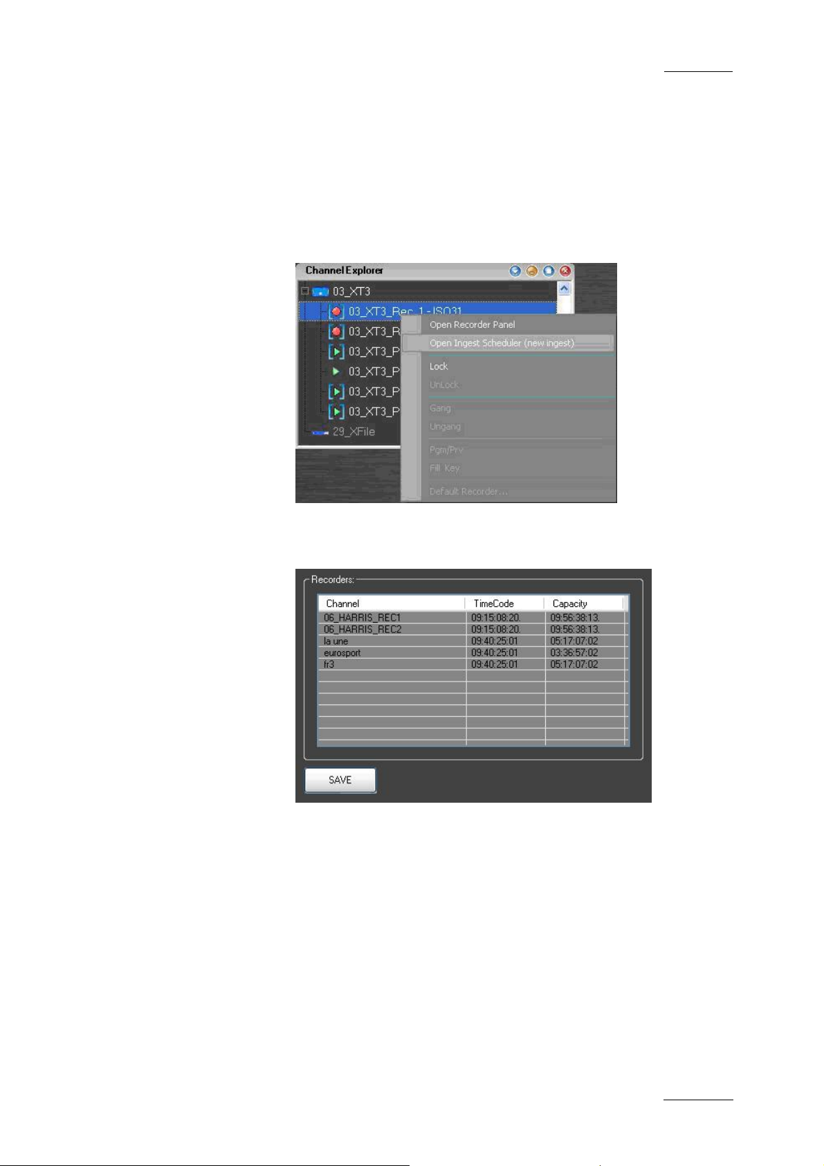
IP Director Version 4.3 – User Manual – Part 1: Introduction
EVS Broadcast Equipment
3.4.10 HOW TO ASSIGN A RECORD CHANNEL FOR USE WITH IP SCHEDULER
To assign a record channel for use with the IP Scheduler
application right-click on a channel to open the contextual menu
and select the ‘Open Ingest Scheduler (new ingest)’ command.
Issue 4.3.C
An Ingest Scheduler window will open and show the selected
channel in the list of recorders.
If the contextual men u is used when record channels are gang ed
together all ganged channels will be added to the list.
If you wish to add multiple recorders to the list, simply drag the
individual channel from the Channel Explorer to this list.
53
Page 65

Issue 4.3.C
IP Director Version 4.3 – User Manual – Part 1: Introduction
EVS Broadcast Equipment
ASSIGNING SHUTTLEPRO FOR USE WITH A
CHANNEL
Pressing the ‘Select Player’ key on the ShuttlePRO controller at
any time calls up a list of channels available to be controlled, by
moving the jog dial you can move through the list to highlight the
required channel and press ‘Select Player’ again to select and
exit the menu
The
icon is displayed on the same line as the
corresponding channel in the channel explorer, meaning the
Shuttle pro will control that channel.
Please see the ShuttlePRO section of the Manual for more
information on the operation of the controller
54
Page 66

IP Director Version 4.3 – User Manual – Part 1: Introduction
EVS Broadcast Equipment
A
add
layout to layout toolbar · 23
application toolbar · 21
main window · 13
assign
default recorder to player channel · 47
player channel to control panel · 47
recorder channel · 53
associate
channels in Fill and Key mode · 52
channels in PGM/PRV mode · 51
clip to log sheet · 19
auxiliary track
settings · 18
B
bar
menu in main window · 12
Issue 4.3.C
default player
set up in Channel Explorer · 48
default play-list
status bar · 28
default recorder
assign to player channel · 47
define
shortcuts · 20
delete
layout · 42
logging profile · 19
display
XT stucture · 17
F
file menu · 15
Fill and Key mode
associate channels · 52
freeze
workspace · 21
G
C
change
password · 21
channel
lock in Channel Explorer · 49
unlock in Channel Explorer · 49
Channel Explorer · 44
gang player channels · 49
lock channel · 49
shortcuts · 46
ungang player channels · 50
unlock channel · 49
XT server status · 45
channel status · 46
main window · 14
panel · 24
channel status panel
close · 25
open · 25
clip
all status and history · 20
status and history · 20
close
all windows · 16
channel status panel · 25
create
layout toolbar · 22
new layout · 41
gang
player channel · 49
GPI
settings · 18
green information · 15
H
help
menu · 21
history
all clips · 20
own clips · 20
I
IP Director
main window · 12
K
key default output
setting · 17
keyboard
lock · 21
D
default bin
status bar · 28
default channel
status bar · 28
L
language
setting · 17
layout
add to layout toolbar · 23
55
Page 67

Issue 4.3.C
IP Director Version 4.3 – User Manual – Part 1: Introduction
EVS Broadcast Equipment
create · 41
delete · 42
menu · 16, 40
open · 41
panel · 22
publish · 43
save · 42
save as · 42
view properties · 43
layout panel
main window · 13
layout toolbar
commands · 24
create · 22
loaded layout
status bar · 29
lock
channel in Channel Explorer · 49
keyboard · 21
log off · 15
logging
associate clip to log sheet · 19
delete profile · 19
refresh assocations · 19
refresh keywords · 19
logging manager · 18
M
main window
channel status · 14
IP Director · 12
layout panel · 13
menu bar · 12, 13
status bar · 14
workspace · 14
menu
file · 15
help · 21
layout · 16, 40
metadata · 16
metatadata · 36
tools · 16
view · 15
windows · 16
menu bar
main window · 12
message box · 15
message panel · 30
metadata
menu · 16
metatadata · 34
change current profile · 37
current profile · 35
menu · 36
modify profile default values · 38
reset profile default values · 39
minimised icon
status bar · 29
modify
metadata default values · 38
move status panel · 31
O
open
channel status panel · 25
existing layout · 41
P
panel
layout · 22
password
change · 21
PGM/PRV mode
associate channels · 51
player
channel status · 14
set up default in Channel Explorer · 48
player channel
assign to control panel · 47
gange · 49
ungang · 50
player status panel
displayed information · 26
possible actions · 26
play-list
settings · 18
process status icons · 33
profile
change current metatadata profile · 37
current metadata profile · 35
metadata · 34
modify metadata default values · 38
reset metadata default values · 39
publish
layout · 43
R
recorder
assign default to player channel · 47
channel status · 14
recorder channel
assign · 53
recorder status panel · 25
displayed information · 25
possible actions · 25
recreate
all thumbnails · 20
refresh
assocations between logs and clips for log sheet · 19
associations between logs and clips · 19
keywords associated with clip in log sheet · 19
reset
metadata default values · 39
S
save
layout · 42
save as
layout · 42
server configuration · 45
56
Page 68

IP Director Version 4.3 – User Manual – Part 1: Introduction
EVS Broadcast Equipment
Issue 4.3.C
server status · 45
set up
default player in Channel Explorer · 48
setting
key default output · 17
language · 17
settings · 16
auxiliary track · 18
clip creation · 18
general · 17
GPI · 18
play-list · 18
take effect · 18
transport · 18
shortcuts
Channel Explorer · 46
define · 20
status
all clips · 20
channel · 46
channel status panel · 24
own clips · 20
process icons · 33
status bar · 27
default bin · 28
default channel · 28
default play-list · 28
loaded layout · 29
main window · 14
minimised icon · 29
status panel
copy/move · 31
T
tools
menu · 16
transfer
information · 20
transport
settings · 18
U
ungang
player channel · 50
unlock
channel in Channel Explorer · 49
V
VGA
green information · 15
view
layout properties · 43
view menu · 15
W
windows
close all · 16
menu · 16
workspace
freeze · 21
main window · 14
take effect
settings · 18
thumbnails
recreate all · 20
toolbar
application · 21
X
XT structure
display · 17
57
 Loading...