

EVERLIGHT ELECTRONICS CO.,LTD.
Technical Data Sheet
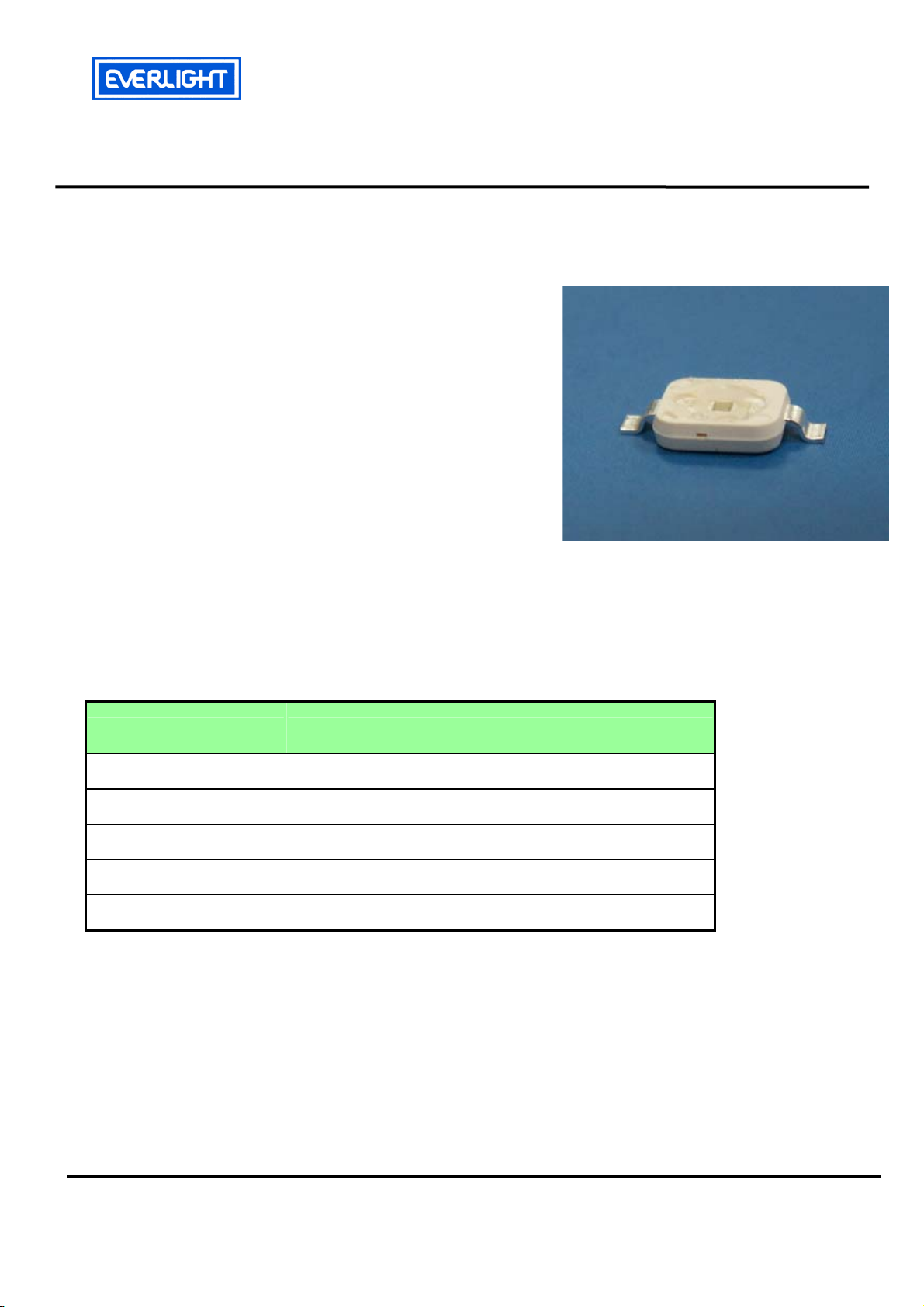
High Power LED – 1W
Features
z feature of the device: small package with high efficiency
z View angle: 120°.
z high luminous flux output: more than 45lm@350mA.
z ESD protection.
z soldering methods: SMT.
z grouping parameter: total luminous flux, dominant
wavelength.
z optical efficiency: 34 lm/W.
z Thermal resistance (junction to lead): 17 K/W.
z RoHS: The product itself will remain within RoHS
compliant version
Applications
z TFT LCD display backlight
z Decorative and entertainment illumination
z Signal and symbol luminaries for orientation marker
lights (e.g. steps, exit ways, etc.)
z Exterior and interior automotive illumination
EHP-A07/SUG01-P01
Materials
Items Description
Housing Heat resistant polymer
Encapsulating Resin Clear silicone resin
Electrodes Ag plating copper alloy
Die attach Silver paste
Chip InGaN
Everlight Electronics Co., Ltd. http://www.everlight.com Rev. 2.0 Page: 1 of 10
Device No. : DSE-7N1-001 Prepared date: Sep 10, 2006 Prepared by: Peggy Chen
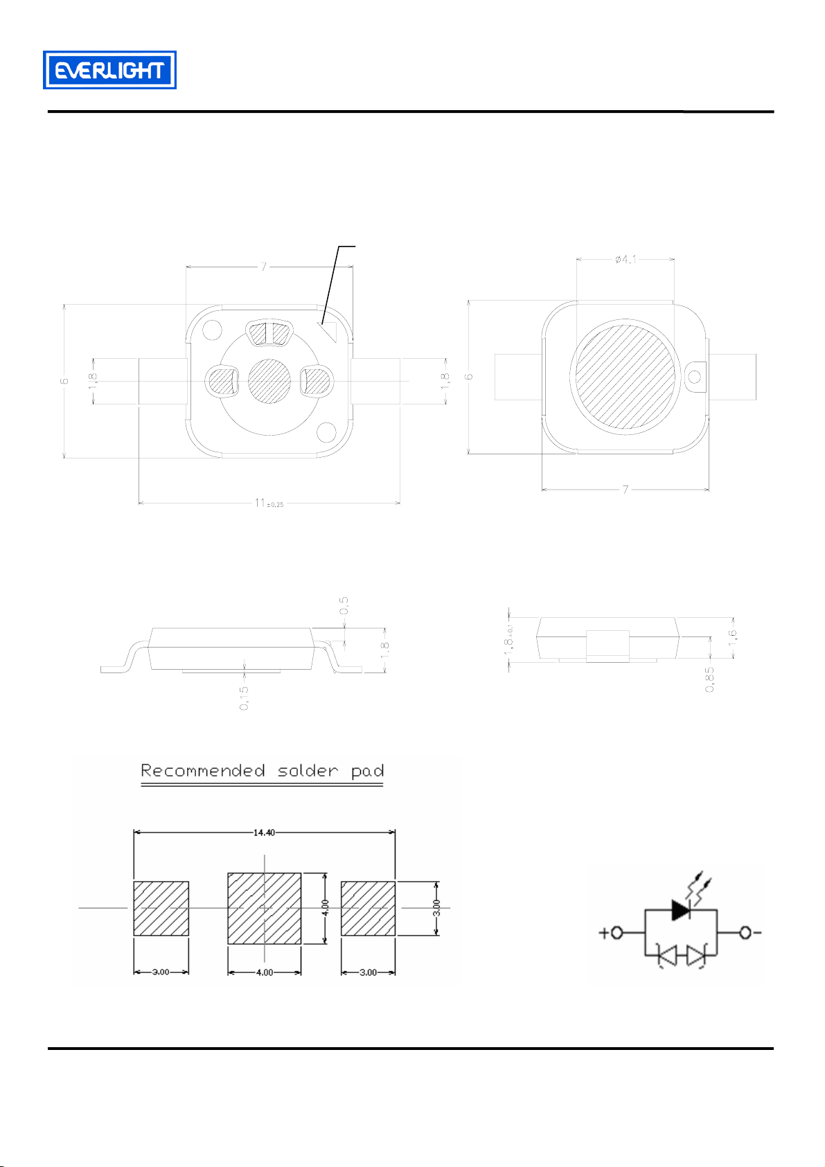
Dimensions
EVERLIGHT ELECTRONICS CO.,LTD.
EHP-A07/SUG01-P01
Cathode mark
Notes: 1. Dimensions are in millimeters
2. Tolerances unless dimensions ±0.25mm
Everlight Electronics Co., Ltd. http://www.everlight.com Rev. 2.0 Page: 2 of10
Device No. : DSE-7N1-001 Prepared date: Sep 10, 2006 Prepared by: Peggy Chen
EVERLIGHT ELECTRONICS CO.,LTD.
EHP-A07/SUG01-P01
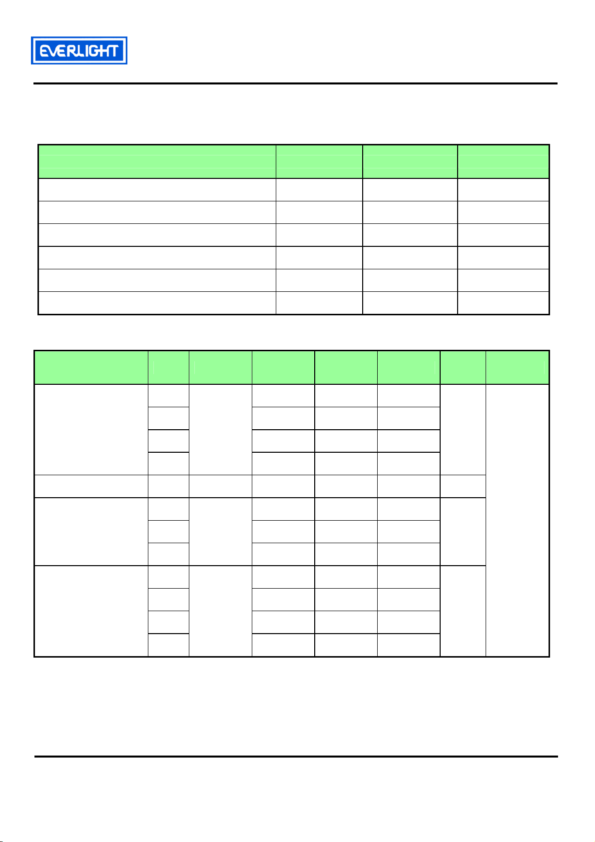
Maximum Ratings (T
Ambient
=25ºC)
Parameter Symbol Rating Unit
Operating Temperature
Storage Temperature
Junction temperature
Forward Current
Power Dissipation
Junction to heat-sink thermal resistance
T
opr
T
stg
T
j
I
F
P
d
R
th
-40 ~ +100 ºC
-40 ~ +100 ºC
125 ºC
500 mA
2.0 W
17 K/W
Electro-Optical Characteristics (T
Parameter Bin Symbol Min Typ. Max Unit Condition
J3 33
J4 39
Luminous Flux
(1)
J5 45
Ф
Ambient
v
=25ºC)
----
----
----
39
45
lm
52
Viewing Angle
(2)
Forward Voltage
(3)
K1
---V2
V3
V4
2θ
1/2
V
F
52
---- 120 ---- deg
3.25
3.55
3.85
C6 515 ---- 520
G1 520 ---- 525
Wavelength
(4)
λ
d
G2 525 ---- 530
G3
Note. 1. Luminous flux measurement tolerance : ±10%
2. 2θ
3. Forward Voltage measurement tolerance : ±0.1V
4. Wavelength measurement tolerance : ±1nm
is the off axis angle from lamp centerline where the luminous intensity is 1/2 of the peak value.
1/2
530 ---- 535
----
----
----
----
60
3.55
3.85
4.15
V
nm
=350mA
I
F
Everlight Electronics Co., Ltd. http://www.everlight.com Rev. 2.0 Page: 3 of10
Device No. : DSE-7N1-001 Prepared date: Sep 10, 2006 Prepared by: Peggy Chen

EVERLIGHT ELECTRONICS CO.,LTD.
A
A
g
EHP-A07/SUG01-P01
Typical Electro-Optical Characteristics Curves
100
80
60
40
20
Relative Luminous Intensity (%)
0
1.2
1.0
0.8
0.6
0.4
Relative Luminous Intensity
0.2
Relative Spectral Distribution,
=350mA, T
I
F
400 500 600 700 800
Wavelength (nm)
Ambient
=25ºC
Relative Luminous Intensity vs Forward
Current, T
0 100 200 300 400 500
=25ºC
mbient
Forward Current (mA)
Forward Voltage vs Forward Current,
mbient
=25ºC
Forward Current (mA)
T
3.8
3.6
3.4
3.2
Forward Voltage (Volt)
3.0
2.8
0 100 200 300 400 500
Forward Current Derating Curve,
Deratin
400
350
300
250
200
Forward Current (mA)
150
100
020406080100
based on T
Ambient Temperature (οC)
JMAX
=125°C
Everlight Electronics Co., Ltd. http://www.everlight.com Rev. 2.0 Page: 4 of10
Device No. : DSE-7N1-001 Prepared date: Sep 10, 2006 Prepared by: Peggy Chen

EVERLIGHT ELECTRONICS CO.,LTD.
Typical Representative Spatial Radiation Pattern
0
1.0
1.0
0.9
0.9
0.8
0.8
0.7
0.7
0.6
0.6
0.5
0.5
0.4
0.4
0.3
0.3
Relative In te n s ity
Relative In te n s ity
0.2
0.2
0.1
0.1
0.0
0.0
-90-80-70-60-50-40-30-20-10 0
-90-80-70-60-50-40-30-20-10 0
Angle (Degree)
Angle (Degree)
0
10
10
20
20
EHP-A07/SUG01-P01
30
30
40
40
50
50
60
60
70
70
80
80
90
90
Everlight Electronics Co., Ltd. http://www.everlight.com Rev. 2.0 Page: 5 of10
Device No. : DSE-7N1-001 Prepared date: Sep 10, 2006 Prepared by: Peggy Chen

EVERLIGHT ELECTRONICS CO.,LTD.
EHP-A07/SUG01-P01
Label explanation
CPN: Customer’s Production Number
P/N : Production Number
QTY: Packing Quantity
CAT: Ranks
HUE: Peak Wavelength
REF: Reference
LOT No: Lot Number
MADE IN TAIWAN: Production Place
Reel Dimensions
Note: 1. Dimensions are in millimeters
2. The tolerances unless mentioned is ±0.1mm
Everlight Electronics Co., Ltd. http://www.everlight.com Rev. 2.0 Page: 6 of10
Device No. : DSE-7N1-001 Prepared date: Sep 10, 2006 Prepared by: Peggy Chen

EVERLIGHT ELECTRONICS CO.,LTD.
Carrier Tape Dimensions: Loaded quantity 800 PCS per reel.
EHP-A07/SUG01-P01
Note: 1. Dimensions are in millimeters
2.The tolerances unless mentioned is ±0.1mm
Moisture Resistant Packaging
Label
Everlight Electronics Co., Ltd. http://www.everlight.com Rev. 2.0 Page: 7 of10
Device No. : DSE-7N1-001 Prepared date: Sep 10, 2006 Prepared by: Peggy Chen
Aluminum moistue-proof bag
LabelDesiccant

EVERLIGHT ELECTRONICS CO.,LTD.
EHP-A07/SUG01-P01
Reliability Test Items and Results
Stress Test Stress Condition Stress Duration
Solderability
Reflow
Thermal Shock
Temperature Cycle
High Temperature/Humidity
Reverse Bias
High Temperature Storage Ta=110℃ 1000hours
Low Temperature Storage Ta=-40℃ 1000hours
Intermittent operational Life
High Temperature Operation
Life #1
Tsol=230℃, 5sec
Tsol=260℃, 10sec, 6min
H:+110℃ 20min.
'∫ 10sec.
'L:- 40℃ 20min.
H:+100℃ 30min.
'∫ 5min.
'L:- 40℃ 30min.
Ta=85℃ , RH=85%
Ta=25℃, IF=1000mA
30mS on/ 2500mS off
Ta=55℃, IF=350mA 1000hours
1 times
3 times
500 Cycles
1000 Cycles
1000hours
1000hours
High Temperature Operation
Life #2
High Temperature Operation
Life #3
Low Temperature Operation
Life
Power Temperature Cycle
ESD Human Body Model 2000V, Interval:0.5sec 3 times
ESD Machine Model 200V, Interval:0.5sec 3 times
*lm: BRIGHTNESS ATTENUATE DIFFERENCE(1000hrs)<50%
*VF: FORWARD VOLTAGE DIFFERENCE<20%
Ta=85℃, IF=225mA 1000hours
Ta=100℃, IF=150mA 1000hours
Ta=-40℃, IF=350mA 1000hours
H:+85℃ 15min.
'∫ 5min.
'L:- 40℃ 15min.
IF=225mA,2min on/off
1000cycles
Everlight Electronics Co., Ltd. http://www.everlight.com Rev. 2.0 Page: 8 of10
Device No. : DSE-7N1-001 Prepared date: Sep 10, 2006 Prepared by: Peggy Chen

EVERLIGHT ELECTRONICS CO.,LTD.
EHP-A07/SUG01-P01
Precautions For Use
1. Over-current-proof
Though EHP-A07 has conducted ESD protection mechanism, customer must not use the device in
reverse and should apply resistors for extra protection. Otherwise slight voltage shift may cause
enormous current change and burn out failure would happen.
2. Storage
i. Do not open moisture proof bag before the products are ready to use.
ii. Before opening the package, the LEDs should be kept at 30℃ or less and 90%RH or less.
iii. The LEDs should be used within a year.
iv. After opening the package, the LEDs should be kept at 30℃ or less and 70%RH or less.
v. The LEDs should be used within 168 hours (7 days) after opening the package.
vi. If the moisture absorbent material (silicone gel) has faded away or the LEDs have exceeded the
storage time, baking treatment should be performed using the following conditions.
vii. Pre-curing treatment : 60±5℃ for 24 hours.
3. Thermal Management
i. Because EHP-A07 LED is a high power dissipation device, special and sufficient consideration in
thermal management design must be made to optimize the thermal performance.
ii. Heat sink design is implemented in the device for an additional thermal connection. Since the device
is capable of SMT process, tin must be spread both heat sink and solder pads areas to dissipate the
heat.
iii. A high thermal conductivity substrate, such as Aluminum or Copper plate etc, must be applied for
external thermal management. It is strongly recommended that the outer heat sink or PCB
dimension per LED can not be less than 25 x 25 x 1 (L x W x H) mm. The materials for outer heat
sink can be FR4 on Aluminum, MCPCB, or FPC on Aluminum.
iv. Sspecial thermal designs are also recommended to take in outer heat sink design, such as FR4 PCB
on Aluminum with thermal vias or FPC on Aluminum with thermal conductive adhesive, etc.
v. Sufficient thermal management must be conducted, or the die junction temperature will be over the
limit under large electronic driving and LED lifetime will decrease critically.
Everlight Electronics Co., Ltd. http://www.everlight.com Rev. 2.0 Page: 9 of10
Device No. : DSE-7N1-001 Prepared date: Sep 10, 2006 Prepared by: Peggy Chen

EVERLIGHT ELECTRONICS CO.,LTD.
4. Soldering Condition
i. Lead reflow soldering temperature profile
ii. Reflow soldering should not be done more than two times.
iii. While soldering, do not put stress on the LEDs during heating.
iv. After soldering, do not warp the circuit board
EHP-A07/SUG01-P01
5. Soldering Iron
i. For prototype builds or small series production runs it is possible to place and solder the LED by
hand.
ii. Dispensing thermal conductive glue or grease on the substrates and follow its curing spec. Press
LED housing to closely connect LED and substrate.
iii. It is recommended to hand solder the leads with a solder tip temperature of 280°C for less than 3
seconds within once in less than the soldering iron capacity 25W. Leave two seconds and more
intervals, and do soldering of each terminal.
iv. Be careful because the damage of the product is often started at the time of the hand solder.
6. Handling Indications
During processing, mechanical stress on the surface should be minimized as much as possible. Sharp
objects of all types should not be used to pierce the sealing compound.
Everlight Electronics Co., Ltd. http://www.everlight.com Rev. 2.0 Page: 10 of10
Device No. : DSE-7N1-001 Prepared date: Sep 10, 2006 Prepared by: Peggy Chen
 Loading...