

Page 1
EVCO S.p.A. Vcolor 338 S | Installer manual ver. 1.2 | Code 144VC338SE124
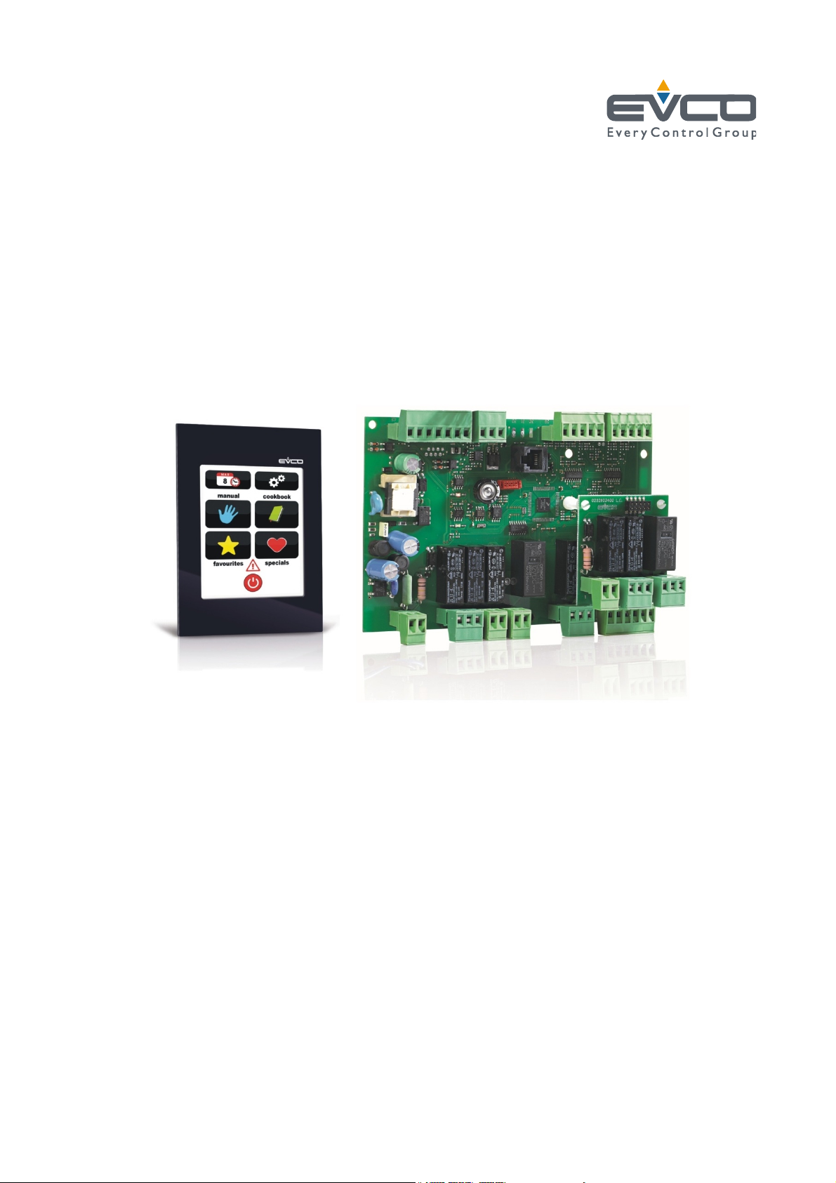
Vcolor 338 S
Controller for "top-class" electric ovens for
gastronomy and confectionery, with TFT
graphic display colour touch-screen, in split
version and can be integrated into the unit
Installer manual | ENGLISH
Code 144VC338SE124
page 1 of 50
Page 2

EVCO S.p.A. Vcolor 338 S | Installer manual ver. 1.2 | Code 144VC338SE124
Important
Read th is document thoroughly b efore installation and before
use of the device and follow all recommendations; keep this
document with the device for future consultation.
Only use the device in the way described in this document; do
not use the same as a safety device.
Disposal
The device must be disposed of in compliance with local
Standards regarding the collection of electric and electronic
equipment.
page 2 of 50
Page 3

EVCO S.p.A. Vcolor 338 S | Installer manual ver. 1.2 | Code 144VC338SE124
Index
1 INTRODUCTION .............................................. 4
1.1 Introduction ................................................... 4
1.2 Summary table of the models available, the main
features and the purchase codes ....................... 5
2 DIMENSIONS AND INSTALLATION ..................... 7
2.1 User interface dimensions ................................ 7
2.2 Installation of user interface at rear of panel ...... 7
2.3 Panel installation (from front panel) ................... 8
2.4 Control module dimensions and installation ........ 8
2.5 Installation warnings ....................................... 9
3 ELECTRIC CONNECTION ................................. 10
3.1 Electric connection ........................................ 10
3.2 Warnings for the electric connection ................ 12
4 DESCRIPTION ............................................... 13
4.1 Description of the user interface...................... 13
4.2 Description of the control module .................... 14
5 COMMISSIONING .......................................... 15
5.1 Commissioning ............................................. 15
6 MANAGEMENT OF UTILITIES ........................... 17
6.1 Preliminary notes .......................................... 17
6.2 Temperature regulation ................................. 17
6.3 Steam injection ............................................. 17
6.4 Vents ........................................................... 17
6.5 Room light ................................................... 17
6.6 Technical compartment fan ............................ 17
6.7 Fan.............................................................. 17
6.8 Steam reduction ........................................... 18
7 USER INTERFACE .......................................... 19
7.1 Switching the device on/off ............................ 19
7.2 Silencing the buzzer ...................................... 19
8 COOKING CYCLE ........................................... 20
8.1 Preliminary notes .......................................... 20
8.2 Setting the cooking cycle ............................... 21
8.3 Starting the cooking cycle .............................. 23
8.4 Stopping the cooking cycle ............................. 23
9 “MY RECIPES” FUNCTION ............................... 24
9.1 Preliminary notes .......................................... 24
9.2 Memorising a recipe ...................................... 24
9.3 Starting a recipe ........................................... 25
9.4 Deleting a recipe ........................................... 25
10 “SPECIAL CYCLES” FUNCTION ......................... 26
10.1 Preliminary notes .......................................... 26
10.2 Starting a special cycle .................................. 27
11 “FAVOURITE CYCLES” FUNCTION .................... 28
11.1 Preliminary notes .......................................... 28
11.2 Starting a favourite cycle ............................... 28
12 "WEEKLY PROGRAMMED SWITCH-ON" FUNCTION
................................................................... 29
12.1 Preliminary notes .......................................... 29
12.2 Setting the "weekly programmed switch-on"
function ....................................................... 29
12.3 Enabling the "Weekly programmed switch-on"
function ....................................................... 30
13 OTHER FUNCTIONS ....................................... 31
13.1 Display of the alarms status ........................... 31
13.2 Display of the process variables value and of the
machine status .............................................. 31
13.3 Setting the language used for the screens ........ 31
14 CONFIGURATION ........................................... 32
14.1 Setting the time, date and day of the week ....... 32
14.2 Setting the configuration parameters ............... 33
14.3 List of configuration parameters ...................... 34
15 USE OF THE USB PORT ................................... 40
15.1 Preliminary information .................................. 40
15.2 Upload of the settings contained in the programs
................................................................... 40
15.3 Downloa d of the settings contained in the
programs...................................................... 40
15.4 Upload of the settings contained in the
configuration parameters ................................ 41
15.5 Downloa d of the settings contained in the
configuration parameters ................................ 41
16 ALARMS ....................................................... 42
16.1 Alarms ......................................................... 42
17 ACCESSORIES ............................................... 44
17.1 Optoisolated RS-485/USB serial interface ......... 44
17.2 USB cap for panel in stallation .......................... 44
17.3 Connection cables 0810500018/0810500020 .... 44
17.4 4 GB USB pen drive EVUSB4096M ................... 44
17.5 Frame for panel installation 0026700005 .......... 45
17.6 Gasket 1010VCOL00 ...................................... 45
18 TECHNICAL DATA .......................................... 46
18.1 Technical data ............................................... 46
page 3 of 50
Page 4

EVCO S.p.A. Vcolor 338 S | Installer manual ver. 1.2 | Code 144VC338SE124
1 INTRODUCTION
1.1 Introduction
Vcolor 338 S is a controller with elegant design for managing
“top-class” electric ovens for gastronomy and confectionery.
It is available in split version and can be integrated both
mechanically and aesthetically into the unit, the user interface
is composed of a TFT touch-screen colour graphic display and
guarantees an IP65 protection rating, for easy
cleaning.
It is able to manage ventilation in "on / off" and modulating
mode (in this case it is necessary to also use an external
speed regulator), with inversion of the direction of rotation of
the fan.
It also manages the steam (injection and vent), both in
automatic and manual mode, of the “weekly programmed
switch-on” and “programmes” functions (the latter to
memorise the cooking settings in a programme, with the
purpose of successively selecting and performing it).
The installation is envisioned behind the panel, with studs (in
this case it guarantees flatness) or in the panel (from the
front), with self-tapping screws and frame (in this case it
requires a reduced depth).
page 4 of 50
Page 5

EVCO S.p.A. Vcolor 338 S | Installer manual ver. 1.2 | Code 144VC338SE124
1.2 Summary table of the models available, the main features and the purchase
codes
The following table illustrates the models available.
Models available Vcolor 338 S
The following table illustrates the main features of the device.
“ / “ indicates the feature can be set via a configuration parameter.
Power supply Vcolor 338 S
115... 230 VAC •
Analogue inputs Vcolor 338 S
environment probe (J/K/Pt 100 2 wires) •
needle probe (J/K/Pt 100 2 wires) •
steam reduction probe (J/K/Pt 100 2 wires) •
Digital inputs (for NO/NC contact) Vcolor 338 S
door micro switch •
fan circuit breaker protection •
On/stand-by •
electric absorption •
fan circuit breaker protection (230 VAC) •
Analogue outputs Vcolor 338 S
0-10 V (fan) •
Digital outputs (electromechanical relays; A res. @ 250
VAC)
temperature adjustment 16 A
Vcolor 338 S
vent 8 A
steam injection 8 A
room light 8 A
technical compartment fan 8 A
load 6 (fan left rotation default) (1) 8 A
page 5 of 50
Page 6

EVCO S.p.A. Vcolor 338 S | Installer manual ver. 1.2 | Code 144VC338SE124
load 7 (fan right rotation default) (2) 8 A
load 8 (fan speed) (3) 16 A
Communication port Vcolor 338 S
RS-485 MODBUS •
USB •
Other features Vcolor 338 S
clock •
alarm buzzer •
management of ventilation both in "On/off" mode and
modulat ing mode, with inversion of fan rotation direction
•
"weekly programmed switch-on" function •
“programs” function •
Notes
(1) can be configured for fan left rotation or fan enabling
(2) can be configured for fan right rotation or fan right/left rotation
(3) can be configured for fan speed or steam reduction.
Options available
None
For further information, see chapter 18 “TECHNICAL DATA”.
The following table illustrates the purchase codes.
Purchase codes EVCSR338J9
For further models, contact the EVCO sales network.
page 6 of 50
Page 7
EVCO S.p.A. Vcolor 338 S | Installer manual ver. 1.2 | Code 144VC338SE124
2 DIMENSIONS AND INSTALLATION
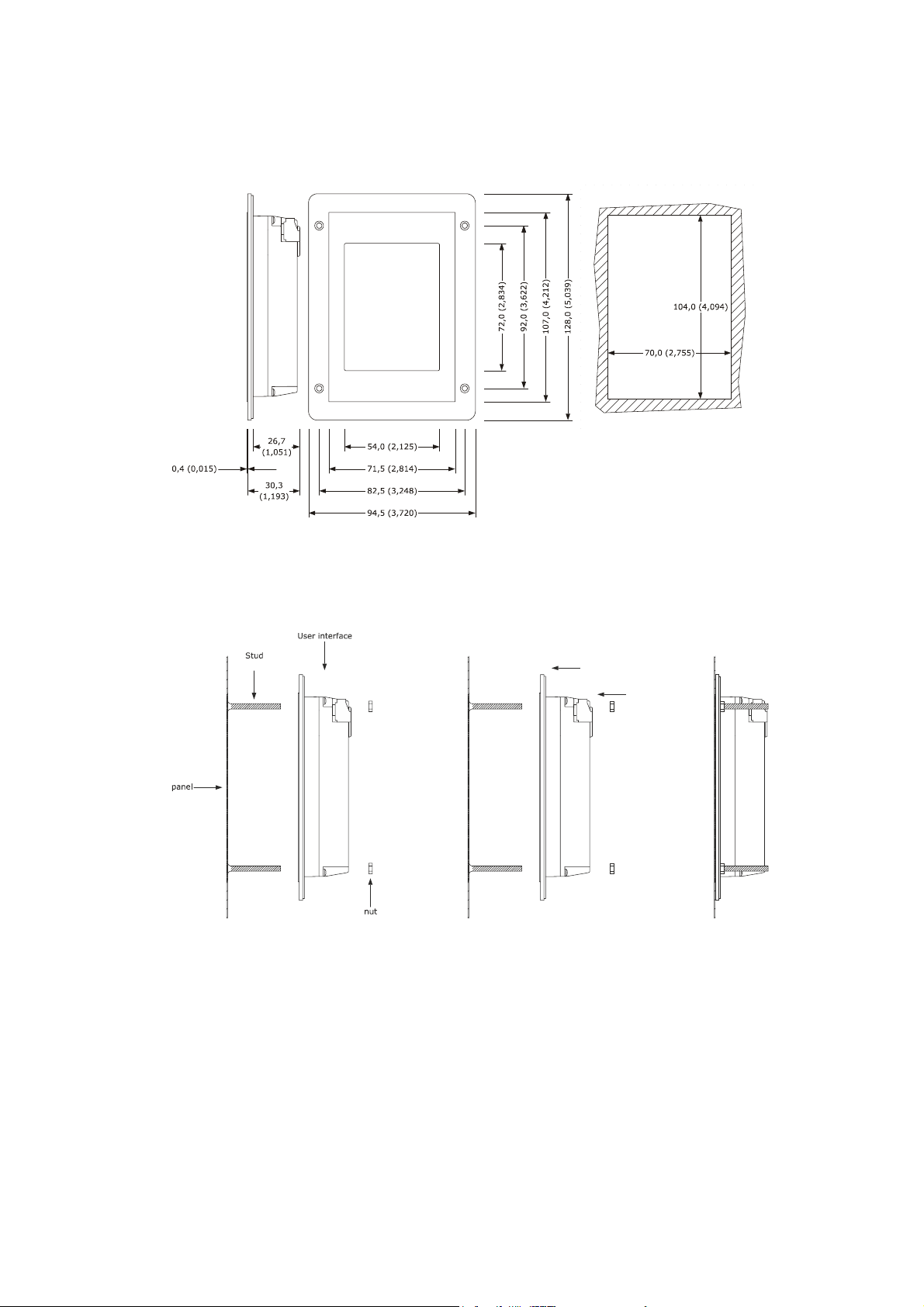
2.1 User interface dimensions
The following drawing illustrates the device's user interface dimensions; these are expressed in mm (in).
2.2 Installation of user interface at rear of panel
The following drawing illustrates the installation behind the panel of the device user interface (with studs)
This type of installat ion is flat.
page 7 of 50
Page 8

EVCO S.p.A. Vcolor 338 S | Installer manual ver. 1.2 | Code 144VC338SE124
2.3 Panel installation (from front panel)
The following drawing illustrates the installation on the panel (from front) of the device user interface (with self-tapping screws and
frame).
Through the gasket 1010VCOL00 (to be ordered separately) it is possible to guarantee the device user interface a protection rating of
IP65; through the frame 0026700005 (to be ordered separately) it is also possible to integrate it aesthetically.
This type of installation requires reduced depth.
2.4 Control module dimensions and installation
The following drawing illustrates the device's control module dimensions; these are expressed in mm (in).
Installation is envisioned on a flat surface, with shims.
page 8 of 50
Page 9

EVCO S.p.A. Vcolor 338 S | Installer manual ver. 1.2 | Code 144VC338SE124
2.5 Installation warnings
- make sure that the device work conditions (temperature of use, humidity, etc.) lie within the limits indicated; see chapter
18 “TECHNICAL DATA”
- do not install the device near to any heat sources (heating elements, hot air ducts etc.), equipment containing powerful
magnets (large diffusers, etc.), areas affected by direct sunlight, rain, humidity, excessive dust, mechanical vibrations or
shocks.
- any metal parts in proximity of the control module must be at a distance such that they do not compromise the safety
distances.
- in compliance with Safety Standards, the device must be installed correctly and in a way to protect against any contact with
electric parts; all parts that ensure protection must be fixed in a way that they cannot be removed without the use of tools.
page 9 of 50
Page 10
EVCO S.p.A. Vcolor 338 S | Installer manual ver. 1.2 | Code 144VC338SE124
3 ELECTRIC CONNECTION
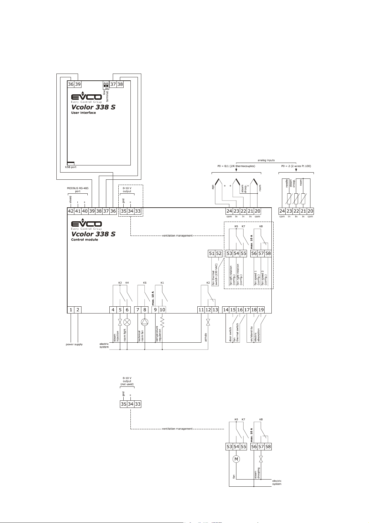
3.1 Electric connection
The following drawing illustrates the device's electric connection.
Management of the ventilation in "on/off" mode and with single speed (parameter F0 = 0).
page 10 of 50
Page 11

EVCO S.p.A. Vcolor 338 S | Installer manual ver. 1.2 | Code 144VC338SE124
Management of the ventilation in "on/off" mode and with single speed and inversion of the fan rotation direction (parameter
F0 = 1).
Management of the ventilation in "on/off" mode and with dual speed and inversion of the fan rotation direction (parameter
F0 = 2).
Management of the ventilation in modulating mode and with inversion of the fan rotation direction (parameter
F0 = 3).
page 11 of 50
Page 12

EVCO S.p.A. Vcolor 338 S | Installer manual ver. 1.2 | Code 144VC338SE124
The RS-485 MODBUS port is the communication port with the following EVCO products:
- parameters Manager set-up software system
- CloudEvolution plants monitoring and surveillance systems (via Web)
The USB communication port that allows the upload and download of the device settings, through a common USB pen drive.
3.2 Warnings for the electric connection
- do not use electric or pneumatic screwdrivers on the device terminal board
- if the device has been taken from a cold to hot place, humidity could condense inside; wait about 1 hour before powering it
- make sure that the power supply voltage, the frequency and the device electric power, correspond with those of the local
power supply; see chapter 18 “TECHNICAL DATA”
- disconnect the device power supply before proceeding with any type of maintenance
- position the power cables as far away as possible from the signal cables
- the terminating resistor must be connected in order to reduce the reflections on the signal transmitted along the cables that
connect the user interface to the control model.
- for repairs and information regarding the device, contact the EVCO sales network.
page 12 of 50
Page 13
EVCO S.p.A. Vcolor 338 S | Installer manual ver. 1.2 | Code 144VC338SE124
4 DESCRIPTION
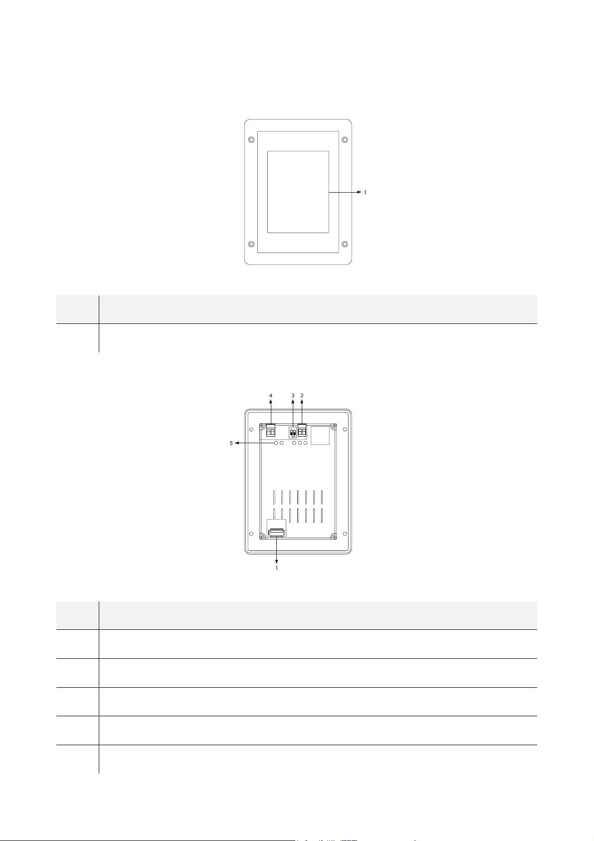
4.1 Description of the user interface
The following drawing illustrates the aspect of the device's user interface front panel.
The following table illustrates the meaning of the front parts of the device user interface parts.
PART MEANING
1 display
The following drawing illustrates the aspect of the device's user interface rear panel.
The following table illustrates the meaning of the rear parts of the device user interface parts.
PART MEANING
1 USB port
2 communication port with the user interface (signal)
3 dip switch for the introduction of the termination resistance
4 communication port with the user interface (power supply)
5 Signal LED
page 13 of 50
Page 14
EVCO S.p.A. Vcolor 338 S | Installer manual ver. 1.2 | Code 144VC338SE124
For further information, see the next chapters.
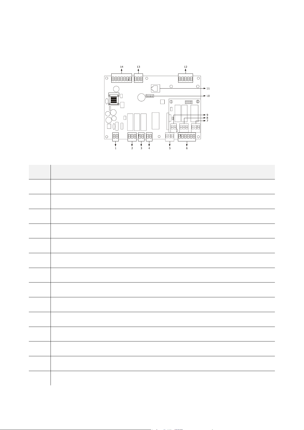
4.2 Description of the control module
The following drawing illustrates the aspect of the device's control module.
The following table illustrates the meaning of device's control module parts.
PART MEANING
1 power supply
2 digital outputs K3 and K4
3 digital output K5
4 digital output K1
5 digital output K2
6 digital inputs for potential-free contact
7 K8 digital output
8 digital inputs K6 and K7
9 digital input for high voltage contact
10 reserved
11 reserved
12 analogue inputs
13 analogue output
14 RS-485 MODBUS port and communication port with user interface
For further information, see the next chapters.
page 14 of 50
Page 15

EVCO S.p.A. Vcolor 338 S | Installer manual ver. 1.2 | Code 144VC338SE124
5 COMMISSIONING
5.1 Commissioning
Operate as indicated:
1. Install the device using the methods illustrated in the 2 “DIMENSIONS AND INSTALLATION” chapter, following all warnings
given in the 2.5 “Installation warnings” paragraph.
2. Connect the device electrically using the methods illustrated in the 3 “ELECTRIC CONNECTION” chapter, following all
warnings given in the 3.2 “Warnings for the electric connection” paragraph, without connecting the power supply and the
mains electricity.
3. Connect the device power supply: a splash screen will be displayed for a few seconds.
4. Set the time, the date and the day of the week; see paragraph 14.1 “Setting the time, date and day of the week”.
5. Configure the device with the procedure illustrated in the paragraph 14.2 “Setting the configuration parameters”.
The following table illustrates the meaning of the configuration parameters; the parameters are listed with the order,
according to which, it is appropriate that the device is configured.
PARAM. MEANING FACTORY SETTING
probe type
P0
0 = thermocouple J
1 = thermocouple K
2 = Pt 100 2 wires
0
P1
P2
F0
t0
unit of measurement
0 = °C
1 = °F
enabling the needle probe
1 = YES
type of fan management
0 = in “on/off” mode and at single speed
1 = in “on/off” mode, with single speed and with inversion of the direct ion of
rotation of the fan
2 = in “on/off” mode, with dual speed and with inversion of the direction o f
rotation of the fan
3 = in modulating mode and with inversion of the direction of rotation of the
fan
steam generation mode
0 = direct
1 = with an external humidifier
2 = combined (i.e. direct and with external humidifier)
0
0
0
0
type of vent output contact
u0
u1
0 = normally open (vent open with closed contact)
1 = normally closed (vent open with open contact)
utility managed by the vent output
0 = ELECTROVALVE ON/OFF
1 = MOTORISED ELECTROVALVE
will assume significance
- in this case the u2, u3 and u4 parameters
page 15 of 50
0
0
Page 16

EVCO S.p.A. Vcolor 338 S | Installer manual ver. 1.2 | Code 144VC338SE124
Successively, check that the remaining settings are appropriate; see paragraph 14.3 “List of configuration parameters”
6. Connect to the electric mains.
7. Switch the device on; see the paragraph 7.1 “Switching the device on/off”.
For further information, see the next paragraphs.
page 16 of 50
Page 17

EVCO S.p.A. Vcolor 338 S | Installer manual ver. 1.2 | Code 144VC338SE124
6 MANAGEMENT OF UTILITIES
6.1 Preliminary notes
This paragraph illustrates the activity of the utilities during
normal operation.
To know the main consequences of an alarm, see chapter 16
“ALARMS”.
6.2 Temperature regulation
The output is switched on until the environment temperature
reaches the work set-point and is turned back on when the
temperature drops below that established with the parameter
r0 (i.e. "working set-point - r0").
To set the work set-point, see paragraph 8.2 “Setting the
cooking cycle”; to set the configuration parameters, see
paragraph 14.2 “Setting the configuration parameters”.
6.3 Steam injection
The steam generation mode depends on parameter t0, as
follows:
- if the parameter t0 is set at 0, the steam will be
generated in direct load
- if the parameter t0 is set at 1, the steam will be
generated with an external humidifier
- if the parameter t0 is set at 2, the steam will be
generated in combined mode (i.e. direct and with
external humidifier); in this case the temperature
established with parameter t12 establishes the
temperature above which the injection of the
steam generated directly will be activated and
below which the injection of steam generated with
external humidifier will be activated (referring to
the temperature detected by the environment
probe).
The parameter t1 establishes the cycle time for the injection of
the steam generated in direct mode and the parameter t2 the
duration of the injection of the steam generated with the same
mode corresponding to the maximum humidification.
The parameter t6 establishes the cycle time for the injection of
the steam generated with external humidifier and the
parameter t7 the duration of the injection of the steam
generated with the same mode corresponding to the maximum
humidification.
To set the humidification, see paragraph 8.2 “Setting the
cooking cycle”; to set the configuration parameters, see
paragraph 14.2 “Setting the configuration parameters”.
6.4 Vents
The utility managed by the vent output, depends on parameter
u0, as follows:
- if the parameter u0 is set at 0, the utility will be
an on/off electrovalve
- if the parameter u0 is set at 1, the utility will be a
motorised electrovalve
The vent is opened automatically on conclusion of each phase
of a cooking cycle.
To set the duration of the automatic vent opening, see the
paragraph 8.2 “Setting the cooking cycle”.
The vent is also opened/closed by touching the area .
6.5 Room light
The environment light is switched on/off by touching the area
.
6.6 Technical compartment fan
The technical compartment fan is on until the temperature of
use of the control module reaches the temperature established
with parameter F6 and is switched back on when the
temperature rises above that established with parameter F7
(i.e. “F6 + F7”).
To set the configuration parameters, see paragraph 14.2
“Setting the configuration parameters”.
6.7 Fan
The type of ventilation management depends on parameter
F0, in the following way:
- if the parameter F0 is set at 0, ventilation will be
managed in “on/off” mode and at single speed
- if the parameter F0 is set at 1, ventilation will be
managed in “on/off” mode and at single speed and
with inversion of the fan rotation direction
- if the parameter F0 is set at 2, ventilation will be
managed in “on/off” mode and at dual speed and
with inversion of the fan rotation direction
- if the parameter F0 is set at 3, ventilation will be
managed in modulating mode and with inversion
of the fan rotation direction
If parameter F0 is set at 0, 1 or 2, parameter F1 will establish
the duration of fan switch off due to the inversion of the
direction of rotation of the same and parameter F2 that of fan
switch-on for every direction of rotation.
If parameter F0 is set at 3, parameter F4 will establish
minimum fan speed and parameter F5 the maximum (intended
as a percentage of maximum speed).
To set the fan speed, see paragraph 8.2 “Setting the cooking
cycle”; to set the configuration parameters, see paragraph
14.2 “Setting the configuration parameters”.
page 17 of 50
Page 18

EVCO S.p.A. Vcolor 338 S | Installer manual ver. 1.2 | Code 144VC338SE124
6.8 Steam reduction
The steam reduction is activated until the temperature
detected by the steam reduction probe reaches the
temperature established with parameter t13 and is turned
back on when the temperature rises above the established
with the parameter t14 (i.e. "t13 + t14", only if the steam
reduction probe is enabled, i.e.if parameter P3 is set at 1).
To set the configuration parameters, see paragraph 15.2
“Setting the configuration parameters”.
page 18 of 50
Page 19

EVCO S.p.A. Vcolor 338 S | Installer manual ver. 1.2 | Code 144VC338SE124
7 USER INTERFACE
7.1 Switching the device on/off
Operate as follows to switch the device on:
1. Touch for 1 s.
Operate as follows to switch the device off:
2. Make sure no procedures are in progress.
3. Touch for 1 s.
If there is a power cut when the device is on or off, when the
power supply is restored, the device will switch-off
If there is a power cut during the cooking cycle and the
duration of said interruption is lower than the time established
with parameter r12, when the power supply is restored, the
cycle will be re-proposed from the start of the phase during
which the power cut occurred (if vice versa the duration of the
interruption is longer than the time established with parameter
r12, when the power supply is restored, the cycle will be
interrupted).
7.2 Silencing the buzzer
Operate as follows to silence the buzzer:
1. Make sure no procedures are in progress.
2. Touch a sensitive area of the display.
Device switch-on.
Device switch-off.
page 19 of 50
Page 20

EVCO S.p.A. Vcolor 338 S | Installer manual ver. 1.2 | Code 144VC338SE124
8 COOKING CYCLE
8.1 Preliminary notes
Every cooking cycle is preceded by preheating (on condition
that Delta T cooking has not been set; the work set-point is
relative to the work set-point during the first phase of the
cooking cycle, i.e. "work set-point during the first phase of the
cooking cycle + work set-point during preheating").
During pre-heat the fan is switched-on at maximum speed.
When the temperature detected by the environment probe
reaches the work set-point, the buzzer is activated for 3 s.
The opening and closing of the door causes the passage to the
first phase of the cooking cycle.
Every cooking cycle is made up from a minimum of one to a
maximum of six phases; on conclusion of a phase, the device
passes automatically to the next.
For every phase, the device can manage the following
settings:
- the type of cooking:
- timed (in this case, the phase has
duration for the time set and the work
set-point is an absolute value)
- with Delta T (only if the needle probe
is enab led, i.e. if parameter P2 is set
at 1; in this case, the phase has
duration until the temperature
detected by the needle probe reaches
the core set-point and the work set-
point is relative to the temperature
detected by the needle probe, i.e.
“temperature detected by the needle
probe + Delta T set-point)
- core (only if the needle probe is
enabled, i.e. if the parameter P2 is set
at 1; in this case, the phase has
duration until the temperature
detected by the needle probe reaches
the core set-point and the work set-
point is an absolute value )
- the work set-point (only if timed or core cooking
has been set)
- the Delta T set-point (only if Delta T cooking has
been set)
- the humidification
- the duration of the phase (only if timed cooking
has been set)
- the core set-point (only if Delta T or core cooking
has been set)
- the fan speed (only if fan management has been
set in “on/off” mode with dual speed or in
modulat ing mode, i.e. if the parameter F0 is set at
2 or 3)
- the duration of the vent automatic opening,
intended as an advance on the conclusion of the
phase (only if timed cooking has been set).
page 20 of 50
Page 21

EVCO S.p.A. Vcolor 338 S | Installer manual ver. 1.2 | Code 144VC338SE124
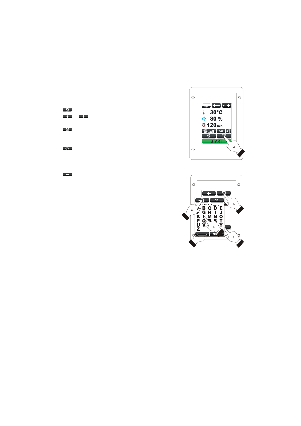
8.2 Setting the cooking cycle
Operate as follows to set the cooking type:
1. Ensure that the device is switched on and that no
other procedure is in progress.
2. Touch .
3. Touch to set:
- the cooking time (2a)
- the cooking at Delta T (2b)
- the core cooking (2c).
Operate as follows to set the work set-point:
4. Touch .
5. Touch or within 15 s; see also parameters r1
and r2.
6. Touch the middle of the display.
Operate as follows to set the Delta T set-point:
7. Touch .
8. Repeat points 5. and 6.; see also parameters r7
and r8.
Operate as follows to set the humidification:
9. Touch .
10. Repeat points 5 and 6.
Operate as follows to set the duration of the phase:
11. Touch .
12. Repeat points 5 and 6.
Operate as follows to set the core set-point:
13. Touch .
14. Repeat points 5. and 6.; see also parameters r4
and r5.
Operate as follows to set the fan speed:
15. Touch .
16. Repeat points 5 and 6.
Operate as follows to set the duration of the automatic vent
opening:
17. Touch .
18. Repeat points 5 and 6.
Operate as follows to add a phase to the cooking cycle:
19. Touch .
20. Repeat the 3 points... 18.
Setting the cooking cycle.
Setting the cooking type.
Setting the work set-point.
Addition of a phase to the cooking cycle.
page 21 of 50
Page 22

EVCO S.p.A. Vcolor 338 S | Installer manual ver. 1.2 | Code 144VC338SE124
Operate as follows to select a phase of the cooking cycle:
21. Touch or .
Operate as follows to eliminate a phase from the cooking
cycle:
22. Select the phase.
23. Touch for 1 s.
Selection of a phase of the cooking cycle.
Elimination of a phase from the cooking cycle.
page 22 of 50
Page 23

EVCO S.p.A. Vcolor 338 S | Installer manual ver. 1.2 | Code 144VC338SE124
8.3 Starting the cooking cycle
Operate as follows to start the cooking cycle:
1. Set the cooking cycle; see the paragraph 8.2
“Setting the cooking cycle”.
2. Touch : pre-heating will be started.
The opening and closing of the door causes the
passage to the first phase of the cooking cycle.
During preheat and during the cooking cycle, the display
shows the value of the variables affected by the process and
the relative setting.
To modify the settings; see the paragraph 8.2 “Setting the
cooking cycle”.
Touch:
- to open/close the vent
- to switch the environment light on/off
- to display the value of the process variables
and machine status.
On conclusion of the cooking cycle, the buzzer is activated for
the time established with parameter c0.
Operate as follows to extend the cooking cycle:
3. Touch .
4. Touch or within 15 s
5. Touch the middle of the display.
8.4 Stopping the cooking cycle
Operate as follows to stop the cooking cycle:
1. Make sure no procedures are in progress.
2. Touch for 1 s.
Starting the cooking cycle.
Pre-heat.
Extension of the cooking cycle.
Stopping the cooking cycle.
page 23 of 50
Page 24
EVCO S.p.A. Vcolor 338 S | Installer manual ver. 1.2 | Code 144VC338SE124
9 “MY RECIPES” FUNCTION
9.1 Preliminary notes
"The My Recipes" function allows to memorise the settings of a
cooking cycle in a recipe; on start-up of the recipe the device
will function with the settings memorised within itself.
It is possible to memorise up to max. 99 recipes.
9.2 Memorising a recipe
Operate as follows to memorise a recipe:
1. Set the cooking cycle; see the paragraph 8.2
“Setting the cooking cycle”.
2. Touch .
3. Touch or to select the position of the
recipe.
4. Touch .
5. Touch the display to associate a name to the
recipe.
6. Touch : the device will leave the procedure.
Operate as follows to exit the procedure before the operation
is complete:
7. Touch before point 4.
Memorising a recipe.
Memorising a recipe.
page 24 of 50
Page 25

EVCO S.p.A. Vcolor 338 S | Installer manual ver. 1.2 | Code 144VC338SE124
9.3 Starting a recipe
Operate as follows to start a recipe:
1. Ensure that the device is switched on and that no
other procedure is in progress.
2. Touch .
3. Touch .
4. Touch or to select the recipe.
5. Touch the middle of the display.
6. Touch the middle of the display again.
7. Touch : the recipe will be activated.
9.4 Deleting a recipe
Operate as follows to delete a recipe:
1. From point 4. of the paragraph 9.3 “Starting a
recipe”, touch for 1 s.
Operate as follows to exit the procedure:
2. Touch .
Access to a recipe.
Starting a recipe.
Deleting a recipe.
page 25 of 50
Page 26

EVCO S.p.A. Vcolor 338 S | Installer manual ver. 1.2 | Code 144VC338SE124
10 “SPECIAL CYCLES” FUNCTION
10.1 Preliminary notes
The “Special cycles” function allows to use the work cycles
made available by EVCO.
One of the following work cycles can be started:
- core regeneration cycle (only if the needle probe is
enabled, i.e. if parameter P2 is set at 1)
- timed regeneration cycle
- timed proving cycle
- environment cooling cycle.
The following table illustrates the factory settings of the core
regeneration cycle.
SETTING DEFAULT
work set-point 110 °C 20... 180 °C
humidification 70 % 40... 100 %
core set-point 70 °C 20... 100 °C
MINIMUM...
MAXIMUM
The following table illustrates the factory settings of the timed
proving cycle.
SETTING DEFAULT
work set-point 30 °C 20... 50 °C
humidification 80 % 40... 100 %
duration of the
phase
fan speed minimum
vent opening on conclusion of the cycle
The following table illustrates the factory settings of the
environment cooling cycle; the opening and closing of the door
does not cause any consequence.
SETTING DEFAULT
120 min 1... 300 min
MINIMUM...
MAXIMUM
MINIMUM...
MAXIMUM
fan speed minimum
vent opening on conclusion of the cycle
The following table illustrates the factory settings of the timed
regeneration cycle.
SETTING DEFAULT
work set-point 110 °C 20... 180 °C
humidification 70 % 40... 100 %
duration of the
phase
fan speed minimum
vent opening on conclusion of the cycle
25 min 1... 90 min
MINIMUM...
MAXIMUM
work set-point
fan speed
vent opening
50 °C
(param. r11)
maximum, without inversion of
rotation direction (if envisioned)
at the start of the cycle, for the
entire duration of the same
0... 500 °C
page 26 of 50
Page 27

EVCO S.p.A. Vcolor 338 S | Installer manual ver. 1.2 | Code 144VC338SE124
10.2 Starting a special cycle
Operate as follows to start a special cycle:
1. Ensure that the device is switched on and that no
other procedure is in progress.
2. Touch .
3. Touch the identification icon of the special cycle.
4. Touch : the special cycle will be
started.
Access to a special cycle.
Starting a special cycle.
page 27 of 50
Page 28

EVCO S.p.A. Vcolor 338 S | Installer manual ver. 1.2 | Code 144VC338SE124
11 “FAVOURITE CYCLES”
FUNCTION
11.1 Preliminary notes
The “Favourite cycles” function allows to start one of the last
10 work cycles performed.
One of the following types of work cycle can be started:
- cooking cycles set with the procedure illustrated in
the paragraph 8.2 “Setting the cooking cycle” (in
this case, the last cycle performed can be started)
- recipes from the “my recipes” function
- “Special cycles” function work cycles.
11.2 Starting a favourite cycle
Operate as follows to start a favourite cycle:
1. Ensure that the device is switched on and that no
other procedure is in progress.
2. Touch .
3. Touch or to select the favourite cycle.
4. Touch the middle of the display.
5. Touch the middle of the display again.
6. Touch : the favourite cycle will be
started.
Access to a favourite cycle.
Starting a favourite cycle.
page 28 of 50
Page 29
EVCO S.p.A. Vcolor 338 S | Installer manual ver. 1.2 | Code 144VC338SE124
12 "WEEKLY PROGRAMMED
SWITCH-ON" FUNCTION
12.1 Preliminary notes
The “Weekly programmed switch-on” function allows to
programme up to a maximum of 9 weekly switch-ons of the
device and simultaneously start a recipe; see chapter 9 ““MY
RECIPES” FUNCTION”.
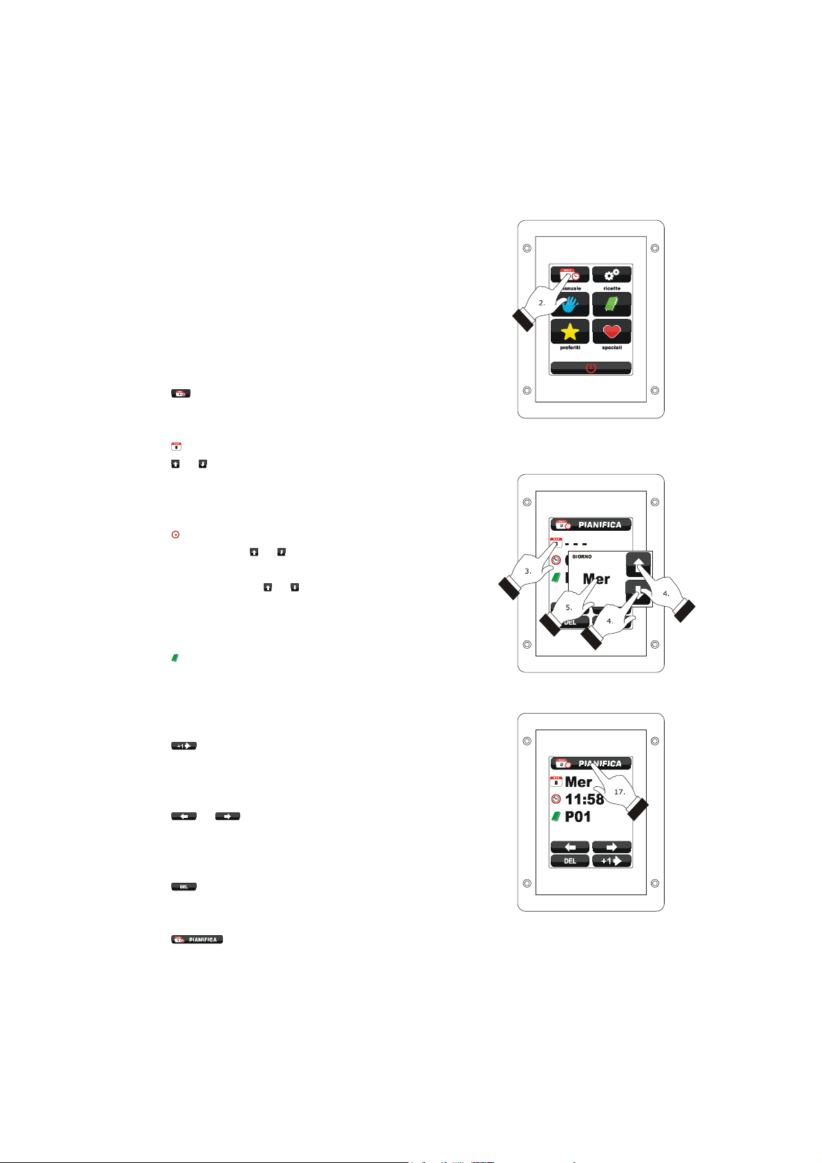
12.2 Setting the "weekly
programmed switch-on"
function
Operate as follows to access the procedure:
1. Ensure that at least one recipe is memorised, that
the device is on and that no other procedure is in
progress.
2. Touch .
Operate as follows to set the switch-on day:
3. Touch .
4. Touch or within 15 s.
5. Touch the middle of the display.
Operate as follows to set the switch-on time:
6. Touch .
7. To set the time, touch or within 15 s.
8. To set the minutes, touch the display in proximity
of the centre, then touch or within 15 s.
9. Touch the middle of the display.
Operate as follows to set the recipe to start-up:
10. Touch .
11. Repeat the 3 points... 5. of paragraph 9.3
“Starting a recipe”.
Operate as follows to programme another switch-on:
12. Touch .
13. Repeat the 3 points... 11.
Operate as follows to select a switch-on:
14. Touch or .
Operate as follows to eliminate a switch-on:
15. Select the switch-on.
16. Touch for 1 s.
Operate as follows to exit the procedure:
17. Touch .
Access to the setting procedure of the
“Weekly programmed switch-on” function.
Setting the switch-on time.
Exit from the settin g procedure of the
“Weekly programmed switch-on” function.
page 29 of 50
Page 30

EVCO S.p.A. Vcolor 338 S | Installer manual ver. 1.2 | Code 144VC338SE124
12.3 Enabling the "Weekly
programmed switch-on"
function
Operate as follows to access the procedure:
1. Ensure that at least one switch-on is set, that the
device is on and that no other procedure is in
progress.
2. Touch for 1 s.
Operate as follows to select a switch-on:
3. Touch or .
Operate as follows to modify a switch-on:
4. Repeat the 3 points... 11. of the paragraph 12.2
“Setting the "weekly programmed switch-on"
function”.
Operate as follows to activate the function:
5. Touch .
Operate as follows to deactivate the function:
6. Touch before point 4.
Access to the function activation procedure
“Weekly programmed switch-on”.
Selection of a switch-on and activation of the function
“Weekly programmed switch-on”.
page 30 of 50
Page 31

EVCO S.p.A. Vcolor 338 S | Installer manual ver. 1.2 | Code 144VC338SE124
13 OTHER FUNCTIONS
13.1 Display of the alarms status
Operate as follows to access the procedure:
1. Ensure that the device is switched on and that no
other procedure is in progress.
2. Touch .
3. Touch to select “LIST OF ALARMS”.
4. Touch the middle of the display.
5. Touch or .
Operate as follows to exit the procedure:
6. Touch .
13.2 Display of the process variables
value and of the machine status
Operate as follows to access the procedure:
1. Ensure that the device is switched on and that no
other procedure is in progress.
2. Touch .
3. Touch to select “INTERNAL VALUES”.
4. Touch the middle of the display.
5. Touch or .
Operate as follows to exit the procedure:
6. Touch .
13.3 Setting the language used for
the screens
Operate as follows to access the procedure:
1. Ensure that the device is switched on and that no
other procedure is in progress.
2. Touch .
3. Touch to select “LANGUAGES” to select the
language.
4. Touch the middle of the display.
5. Touch the middle of the display again.
Operate as follows to exit the procedure:
6. Touch .
page 31 of 50
Page 32

EVCO S.p.A. Vcolor 338 S | Installer manual ver. 1.2 | Code 144VC338SE124
14 CONFIGURATION
14.1 Setting the time, date and day
of the week
Operate as follows to access the procedure:
1. Ensure that the device is switched on and that no
other procedure is in progress.
2. Touch .
3. Touch the middle of the display.
Operate as follows to select a value:
4. Touch .
Operate as follows to set a value:
5. Touch or within 15 s.
6. Touch .
Operate as follows to exit the procedure:
7. Touch .
Operate as follows to exit the procedure before the operation
is complete:
6. Touch before point 6.
Access to the time, date and day of the week setting procedure.
Setting the time, date and day of the week.
page 32 of 50
Page 33

EVCO S.p.A. Vcolor 338 S | Installer manual ver. 1.2 | Code 144VC338SE124
14.2 Setting the configuration
parameters
Operate as follows to access the procedure:
1. Ensure that the device is switched on and that no
other procedure is in progress.
2. Touch .
3. Touch to select “SERVICE”.
4. Touch the middle of the display.
5. Touch within 15 s to set “-19”.
6. Touch the middle of the display.
Operate as follows to select a parameter:
7. Touch or .
Operate as follows to set a parameter:
8. Touch the middle of the display.
9. Touch or within 15 s.
10. Touch the middle of the display.
Operate as follows to exit the procedure:
11. Touch .
Access to the configuration parameters setting procedure.
Access to the configuration parameters setting procedure.
Selection and setting of a configuration parameter.
page 33 of 50
Page 34

EVCO S.p.A. Vcolor 338 S | Installer manual ver. 1.2 | Code 144VC338SE124
14.3 List of configuration parameters
The following table illustrates the meaning of the device configuration parameters.
PARAM. MIN. MAX. U.M. DEF. ANALOGUE INPUTS
probe type
P0 0 2 - - - 0
P1 0 1 - - - 0
0 = thermocouple J
1 = thermocouple K
2 = Pt 100 2 wires
temperature unit of measurement (1)
0 = °C
1 = °F
P2 0 1 - - - 0
P3 0 1 - - - 0
CA1 -25/-50 25/50 °C/°F (2) 0 environment probe alarm
CA2 -25/-50 25/50 °C/°F (2) 0 needle probe offset
CA3 -25/-50 25/50 °C/°F (2) 0 steam reduction probe offset
PARAM. MIN. MAX. U.M. DEF. MAIN REGULATOR
r0 1 99 °C/°F (2) 5
r1 0 r2 °C/°F (2) 0
r2 r1 999 °C/°F (2) 300
enabling the needle probe
1 = YES
enabling of the steam reduction probe
1 = YES
work set-point differential (referring to the temperature detected by
the environment probe)
work set-point minimum (referring to the temperature detected by
the environment probe)
work set-point maximum (referring to the temperature detected by
the environment probe)
r3 r1 r2 °C/°F (2) 130
r4 0 r5 °C/°F (2) 0
r5 r4 999 °C/°F (2) 100
r6 r4 r5 °C/°F (2) 30
work set-point for factory setting (referring to the temperature
detected by the environment probe); see also r0
minimum set-point at the core (referring to the temperature
detected by the needle probe)
maximum set-point at the core (referring to the temperature
detected by the needle probe)
work set-point at the core for factory setting (referring to the
temperature detected by the needle probe)
page 34 of 50
Page 35

EVCO S.p.A. Vcolor 338 S | Installer manual ver. 1.2 | Code 144VC338SE124
r7 0 r8 °C/°F (2) 0
r8 r7 150 °C/°F (2) 30
r9 r7 r8 °C/°F (2) 5
Delta T set-point minimum (referring to the temperature detected by
the needle probe)
Delta T set-point maximum (referring to the temperature detected
by the needle probe)
Delta T set-point for factory setting (referring to the temperature
detected by the needle probe)
work set-point during preheat (relative to the work set-point during
r10 -199 199 °C/°F (2) 10
the first phase of the cooking cycle, i.e. “work set-point during the
first phase of the cooking cycle + r10”; referring to the temperature
detected by the environment probe); see also parameter r0
r11 0 500 °C/°F (2) 50
work set-point during cooling (referring to the temperature detected
by the environment probe)
r12 0 240 min 240 duration of a power supply cut-off (3)
PARAM. MIN. MAX. U.M. DEF. VARIOUS
c0 -1 120 s 10
c1 0 1 - - - 0
duration of buzzer activation on conclusion of the cooking cycle
-1 = as long as it is silenced by hand
activation of the buzzer (for 1 s) on conclusion of a cooking cycle
phase
time that must pass without operations on the device (from
c2 0 240 min 60
activation of the “Weekly programmed switch-on”) until this
switches off
temperature over which the display of the temperature detected by
c3 0 99 °C/°F (2) 10
the environment probe is blocked (relative to the work set-point, i.e.
“work set-point + c3”)
0 = function absent
temperature above which the display of the temperature detected by
c4 0 99 °C/°F (2) 10
the environment probe is blocked (relative to the work set-point, i.e.
“work set-point - c4”)
0 = function absent
PARAM. MIN. MAX. U.M. DEF. FAN
page 35 of 50
Page 36

EVCO S.p.A. Vcolor 338 S | Installer manual ver. 1.2 | Code 144VC338SE124
type of fan management
0 = in “on/off” mode and at single speed
1 = in “on/off” mode, with single speed and with inversion of the
F0 0 3 - - - 0
direction of rotation of the fan
2 = in “on/off” mode, with dual speed and with inversion of the
direction of rotation of the fan
3 = in modulating mode and with inversion of the direction of
rotation of the fan
F1 1 120 s 15
F2 1 600 s 120
duration of the fan switch-off due to the inversion of the direction of
rotation of the same (only if F0 = 0, 1 or 2); see also F2
duration of the fan switch-on for every direction (only if F0 = 0, 1 or
2); see also F1
output switch-off for regulation of the temperature during fan
F3 0 1 - - - 0
switch-off due to the effect of the inversion of direction of rotation of
the same (only if F0 = 1, 2 or 3)
0 = YES
F4 0 F5 % 0
F5 F4 100 % 100
minimum fan speed (intended as a percentage of the maximum
speed; only if F0 = 3)
maximum fan speed (intended as a percentage of the maximum
speed; only if F0 = 3)
temperature above which the technical compartment fan is
F6 20/65 65/150 °C/°F (2) 60
switched-on (referring to the temperature used by the control
module); see also F7
F7 1 99 °C/°F (2) 10 differential of F6
PARAM. MIN. MAX. U.M. DEF. STEAM INJECTION
steam generation mode
t0 0 2 - - - 0
0 = direct
1 = with an external humidifier
2 = combined (i.e. direct and with external humidifier)
t1 t2 999 s 60 cycle time for injection of the steam generated in direct mode
t2 0 t1 s 30
t3 0 999 s 60
duration of the injection of the steam generated in direct mode
corresponding to the maximum humidification
injection delay of the steam generated in direct mode from start of a
cooking cycle phase
page 36 of 50
Page 37

EVCO S.p.A. Vcolor 338 S | Installer manual ver. 1.2 | Code 144VC338SE124
enabling of the restriction between the injection of the steam
generated in direct mode and the fan
t4 0 1 - - - 0
1 = YES
- if the fan is off when the steam is injected, the
injection will be made on successive fan switch-on and if the
fan must switch-off during steam injection, it will be
switched-off on conclusion of the injection
enabling of the restriction between the injection of the steam
generated in direct mode and the output for temperature regulation.
t5 0 1 - - - 0
1 = YES
- if the output is off when the steam is injected, the
injection will be made on successive output switch-on and if
the output must switch-off during steam injection, it will be
switched-off on conclusion of the injection
t6 t7 999 s 60
t7 0 t6 s 30
t8 0 999 s 60
cycle time for injection of the steam generated with an external
humidifier
duration of the injection of the steam generated with external
humidifier corresponding to the maximum humidification
injection delay of the steam generated with external humidifier from
start of a cooking cycle phase
enabling of the restriction between the injection of the steam
generated with external humidifier and the fan
t9 0 1 - - - 0
1 = YES
enabling of the restriction between the injection of the steam
generated with external humidifier and the output for temperature
regulation.
t10 0 1 - - - 0
1 = YES - if the output is off when the steam is injected, the
- if the fan is off when the steam is injected, the
injection will be made on successive fan switch-on and if the
fan must switch-off during steam injection, it will be
switched-off on conclusion of the injection
injection will be made on successive output switch-on and if
the output must switch-off during steam injection, it will be
switched-off on conclusion of the injection
t11 0 240 s 5
delay of injection of the steam from output switch -on for the
regulation of the temperature or from fan switch-on
temperature above which the injection of steam generated in direct
mode is activated and below which the injection of steam generated
t12 0 999 °C/°F (2) 120
with external humidifier is activated (referring to the temperature
detected by the environment probe; only if
t0 = 2)
page 37 of 50
Page 38

EVCO S.p.A. Vcolor 338 S | Installer manual ver. 1.2 | Code 144VC338SE124
temperature above which steam reduction is activated (referring to
t13 0 999 °C/°F (2) 90
the temperature detected by the steam reduction probe); see also
t14
t14 1 99 °C/°F (2) 5 differential of t13
PARAM. MIN. MAX. U.M. DEF. TEMPERATURE ALARMS
A0 1 99 °C/°F (2) 10 differential of A1
temperature higher than that at which the maximum temperature
A1 0 999 °C/°F (2) 0
alarm is activated (referring to the temperature detected by the
environment probe); see also A0 and A3
A2 0 240 min 0 maximum temperature alarm delay
maximum temperature alarm type
A3 0 2 - - - 0
0 = no alarm
1 = absolute (i.e. A1)
2 = relative to the work set-point (i.e. “work set-point + A1”)
temperature above which the temperature of use alarm is activated
A4 0 80/175 °C/°F (2) 70
(referring to the temperature of use of the control module)
0 = no alarm
PARAM. MIN. MAX. U.M. DEF. DIGITAL INPUTS
type of door micro switch input contact
i0 0 1 - - - 0
0 = normally open (input active with closed contact)
1 = normally closed (input active with open contact)
type of fan circuit breaker protection input contact
i1 0 1 - - - 0
0 = normally open (input active with closed contact)
1 = normally closed (input active with open contact)
fan circuit breaker protection input type
i2 0 1 - - - 0
0 = for potential free contact (clamps 14 and 16)
1 = for high voltage contact (clamps 51 and 52)
type of contact of the on/stand-by input
i3 0 1 - - - 0
0 = normally open (input active with closed contact)
1 = normally closed (input active with open contact)
i4 0 1 - - - 0
type of electric absorption input contact
0 = normally open (input active with closed contact)
1 = normally closed (input active with open contact)
page 38 of 50
Page 39

EVCO S.p.A. Vcolor 338 S | Installer manual ver. 1.2 | Code 144VC338SE124
PARAM. MIN. MAX. U.M. DEF. DIGITAL OUTPUTS
type of vent output contact
u0 0 1 - - - 0
0 = normally open (vent open with closed contact)
1 = normally closed (vent open with open contact)
utility managed by the vent output
u1 0 1 - - - 0
0 = ELECTROVALVE ON/OFF
1 = MOTORISED ELECTROVALVE
- in this case the u2, u3 and u4
parameters will assume significance
duration of the inhibition of vent output from the conclusion of the
u2 0 600 ds (s/10) 120
brief impulse for vent opening and from the conclusion of the long
impulse for vent closure (only if u1 = 1); see also u3 and u4
u3 0 600 ds (s/10) 10
u4 0 600 ds (s/10) 30
duration of the brief impu lse for vent opening (only if u1 = 1); see
also u2 and u4
duration of the long impulse for vent closure (only if
u1 = 1); see also u2 and u3
PARAM. MIN. MAX. U.M. DEF. SERIAL NETWORK
LA 1 247 - - - 247 device address
baud rate
0 = 2.400 baud
Lb 0 3 - - - 2
1 = 4.800 baud
2 = 9.600 baud
3 = 19.200 baud
parity
LP 0 2 - - - 2
0 = none (no parity)
1 = odd
2 = even
Notes
(1) Properly set the parameters corresponding to the regulators after setting parameter P1
(2) the unit of measurement depends on P1
(3) if the duration of the power cur is shorter that the time established with parameter r12, when the power supply is restored,
the cycle will be re-proposed from the start of the phase during which the power cut occurred.
page 39 of 50
Page 40

EVCO S.p.A. Vcolor 338 S | Installer manual ver. 1.2 | Code 144VC338SE124
15 USE OF THE USB PORT
15.1 Preliminary information
Through the USB port it is possible to make the following
operations:
- upload and download of the settings contained in
the recipes from the “My recipes” function and
from the “Special cycles” function work cycles
(hereinafter called “programs”)
- upload and download of the settings contained in
the configuration parameters.
The operations are guaranteed with the use of the USB flash
drive EVUSB4096M.
The upload operations are allowed on condition that the
firmware of the device of origin is the same as that of the
device of destination.
15.2 Upload of the settings
contained in the programs
To make the upload of the settings contained in the programs,
operate as follows:
1. Ensure that the device is switched off and that no
other procedure is in progress.
2. Plug in a USB flash drive containing a proper text
document called “prog.txt” in the USB port of the
device and wait a few seconds.
3. Touch to select “Upload programs”.
4. Touch the middle of the display: the upload of the
settings will be started.
5. To the end of the upload remove the USB flash
drive from the USB port of the device.
Operate as follows to exit the procedure before the operation
is complete:
6. Touch before point 4.
15.3 Download of the settings
contained in the programs
To make the download of the settings contained in the
programs, operate as follows:
1. Ensure that the device is switched off and that no
other procedure is in progress.
2. Plug in a USB flash drive in the USB port of the
device and wait a few seconds.
3. Touch the middle of the display: the download of
the settings will be started.
4. To the end of the download remove the USB flash
drive from the USB port of the device.
Operate as follows to exit the procedure before the operation
is complete:
5. Touch before point 3.
Upload of the settings contained in the programs.
Download of the settings contained in the programs.
page 40 of 50
Page 41

EVCO S.p.A. Vcolor 338 S | Installer manual ver. 1.2 | Code 144VC338SE124
15.4 Upload of the settings
contained in the configuration
parameters
To make the upload of the settings contained in the
configuration parameters, operate as follows:
1. Ensure that the device is switched off and that no
other procedure is in progress.
2. Plug in a USB flash drive containing a proper text
document called “param.txt” in the USB port of
the device and wait a few seconds.
3. Touch to select “Upload parameters”.
4. Touch the middle of the display: the upload of the
settings will be started.
5. To the end of the upload remove the USB flash
drive from the USB port of the device.
Operate as follows to exit the procedure before the operation
is complete:
6. Touch before point 4.
15.5 Download of the settings
contained in the configuration
parameters
To make the download of the settings contained in the
configuration parameters, operate as follows:
1. Ensure that the device is switched off and that no
other procedure is in progress.
2. Plug in a USB flash drive in the USB port of the
device and wait a few seconds.
3. Touch to select “Download parameters”.
4. Touch the middle of the display: the download of
the settings will be started.
5. To the end of the download remove the USB flash
drive from the USB port of the device.
Operate as follows to exit the procedure before the operation
is complete:
6. Touch before point 4.
Upload of the settings contained in the configuration parameters.
Download of the settings contained in the configuration parameters.
page 41 of 50
Page 42

EVCO S.p.A. Vcolor 338 S | Installer manual ver. 1.2 | Code 144VC338SE124
16 ALARMS
16.1 Alarms
A buzzer is activated if an alarm occurs, the display shows the icon and an alarm code; touch the display in the centre to silence the
buzzer and restore normal display.
The following table illustrates the meaning of the device alarm codes.
ALARM CODE MEANING
chamber probe alarm
solutions:
- check the type of probe; see parameter P0
Chamber probe
ALARM
- check the device-probe connection
- check the temperature of the chamber
main consequences:
- if the alarm occurs when the device is on, a cooking cycle cannot be started
- if the alarm occurs during an cooking cycle, the cycle will be interrupted
- the output for temperature regulation will be switched-off
Core probe
ALARM
Steam reduction
probe offset
alarm
No voltage
ALARM
core probe alarm
solutions:
- the same as the preceding case but with respect to the core probe
main consequences:
- if the alarm occurs when the device is on, a Delta T and a core cooking cycle cannot be allowed
- if the alarm occurs during a Delta T or core cooking cycle, the cycle will be interrupted
steam reduction probe alarm
solutions:
- the same as the preceding case but with respect to the steam reduction probe
main consequences:
- the output for management of steam reduction will be switched off
power supply cut-off alarm
solutions:
- check the device-power supply connection
main consequences:
- if the alarm occurs when the device is on or off, when the power supply is restores, the device
will switch-off
- if the alarm occurs during the cooking cycle and the duration of said interruption is lower than
the time established with parameter r12, when the power supply is restored, the cycle will be re-
proposed from the start of the phase during which the power cut occurred (if vice versa the
duration of the interruption is longer than the time established with parameter r12, when the
power supply is restored, the cycle will be interrupted).
page 42 of 50
Page 43

EVCO S.p.A. Vcolor 338 S | Installer manual ver. 1.2 | Code 144VC338SE124
user interface-control module communication alarm
solutions:
No connection
ALARM
- check user interface-control module control module
main consequences:
- if the alarm occurs when the device is on, a cooking cycle cannot be started
- if the alarm occurs during an cooking cycle, no consequence
maximum temperature alarm
Temperature
ALARM
solutions:
- check the temperature detected by the environment probe; see parameters A0, A1 and A3
main consequences:
- no consequence
Use temperature alarm.
solutions:
Board
temperature
alarm
ALARM
- check the use temperature of the control module; see parameter A4
main consequences:
- if the alarm occurs when the device is on, a cooking cycle cannot be started
- if the alarm occurs during an cooking cycle, the cycle will be interrupted
- the vent will be open, the technical compartment fan will be on and the remaining outputs will
be off
door micro switch input alarm
solutions:
- check the causes of the activation of the input; see parameter i0
main consequences:
- if the alarm occurs during a cooking cycle, the temperature regulation output, the fan and the
steam injection output will be switched off and the vent will be open
fan circuit breaker protection input alarm
solutions:
Circuit breaker
protection ALARM
- check the causes of the activation of the input; see parameters i1 and i2
main consequences:
- if the alarm occurs during a cooking cycle, the temperature regulation output and the fan will be
switched off
electric absorption input alarm
Peak absor.
ALARM
solutions:
- check the causes of the activation of the input; see parameter i4
main consequences:
- if the alarm occurs during an cooking cycle, the outputs will be off
When the problem that caused the error disappears, the device is restored to normal operation.
page 43 of 50
Page 44
EVCO S.p.A. Vcolor 338 S | Installer manual ver. 1.2 | Code 144VC338SE124
17 ACCESSORIES
17.1 Optoisolated RS-485/USB serial interface
The interface can be used to connect the device to the Parameters Manager set-up software system.
17.2 USB cap for panel installation
The cap can be used to make the device USB communication port more accessible.
To connect the cap to the device, connection cable 0810500018 or 0810500020 must be used (to be ordered separately).
17.3 Connection cables 0810500018/0810500020
The cables can be used to connect the USB cap for panel installation 0812000002 to the device.
The cable 0810500018 measures 2.0 m; the cable 0810500020 measures 0.5 m.
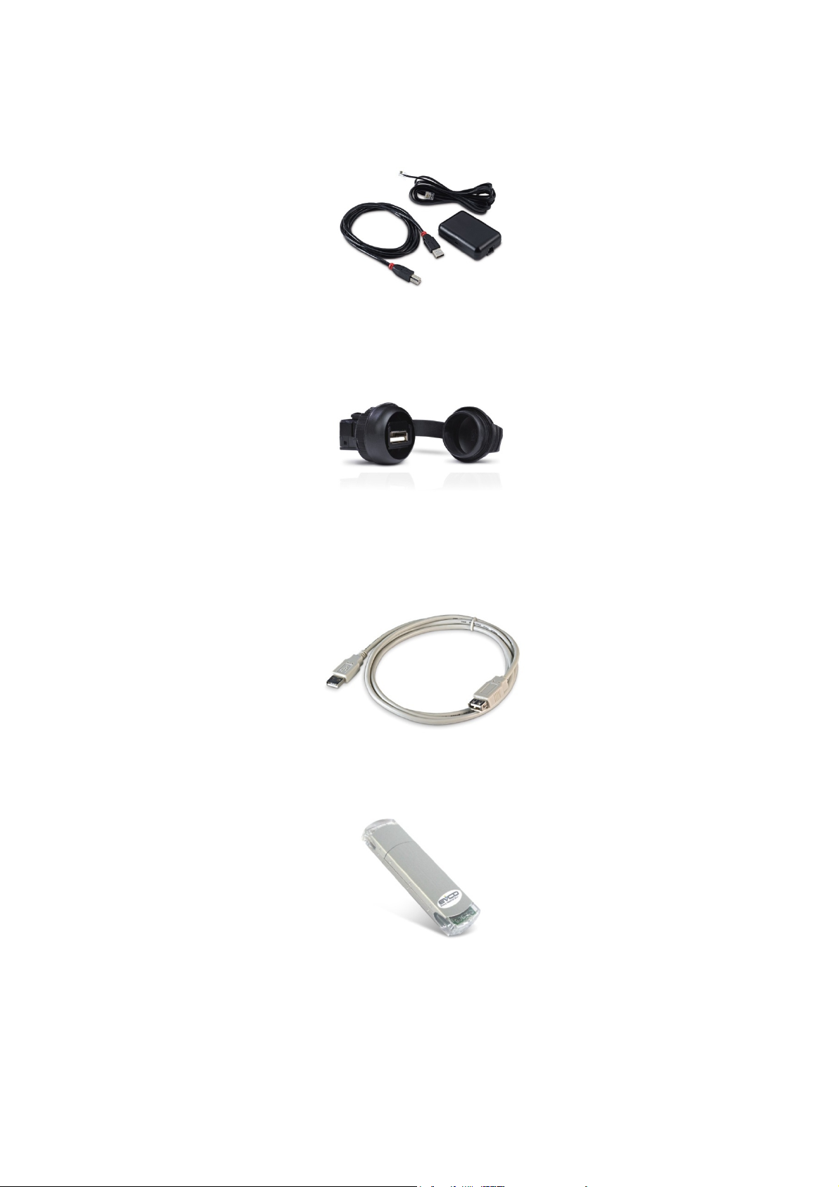
17.4 4 GB USB pen drive EVUSB4096M
Using the pen drive it is possible to upload and download the settings and data recorded by the device.
page 44 of 50
Page 45

EVCO S.p.A. Vcolor 338 S | Installer manual ver. 1.2 | Code 144VC338SE124
17.5 Frame for panel installation 0026700005
Using the frame it is possible to aesthetically integrate the user interface when this is installed on the panel.
17.6 Gasket 1010VCOL00
Using the gasket it is possible to guarantee the user interface a protection rating of IP 65 when it is installed on the panel.
page 45 of 50
Page 46

EVCO S.p.A. Vcolor 338 S | Installer manual ver. 1.2 | Code 144VC338SE124
18 TECHNICAL DATA
18.1 Technical data
Purpose of the command device: operating command device.
Construction of the command device: built-in electronic device.
user interface control module
Case:
black self-extinguishing. board without cover.
user interface control module
Dimensions:
Method of mounting the command device:
Protection rating:
Connections:
94.5 x 128.0 x 30.7 mm (3.720 x
5.039 x 3.068 cm; L x H x D).
user interface control module
behind panel, with studs or on the
panel (front), with self-tapping screws
and frame.
user interface control module
IP40; IP65 in the case of installation
on panel with gasket 1010VCOL00 (to
be ordered separately).
user interface control module
removable screw terminal board
(control module), USB type A
connector (USB port).
166.0 x 116.0 x 44.0 mm (6.535 x
4.566 x 4.399 cm; L x H x D).
on flat surface, with spacers.
IP00.
removable screw terminal board (user
interface, power supply, inputs,
outputs and RS-485 MODBUS port).
The maximum length of the analogue inputs and analogue output connection
cables must be less than 10 m (32,808 ft).
The maximum length of the user interface-control module connection cables
must be less than 10 m (32,808 ft).
Operating temperature: from 0 to 55 °C (from 32 to 131 °F).
Storage temperature: from -10 to 70 °C (from 14 to 158 °F).
Humidity for use: from 10% to 90 % relative humidity without condensate.
Command device pollution situation: 2.
page 46 of 50
Page 47

EVCO S.p.A. Vcolor 338 S | Installer manual ver. 1.2 | Code 144VC338SE124
user interface control module
Power:
supplied from the control module.
Rated impulse voltage: 4 KV.
Overvoltage category: III.
Class and structure of software: A.
incorporated.
Clock:
Autonomy in the event of a power-cut: 24 h with fully charged.
Battery charging time: 2 min (the battery is charged by the device power
supply).
3 inputs (environment probe, needle probe and steam reduction probe), can be
set via configuration parameter for J/K thermocouples or
Pt 100 2 wire probes.
115... 230 VAC (±15%), 50/60 Hz
(±3 Hz), 10 VA max.
Analogue inputs:
Digital inputs:
thermocouple J type analogue inputs
Type of sensor: iron/constantan.
Field of measurement: from -50 to 700°C (from -58 to 1,292 °C).
Resolution: 1 °C (1 °F).
Protection: none.
thermocouple K type analogue inputs
Type of sensor: chromel/alumel.
Field of measurement: from -50 to 1,100°C (from -58 to 2,012 °C).
Resolution: 1 °C (1 °F).
Protection: none.
Pt 100 analogue inputs
Type of sensor: Pt 100 class A.
Field of measurement: from -50 to 550°C (from -58 to 1,022 °C).
Resolution: 1 °C (1 °F).
Protection: none.
5 inputs:
4 inputs (door micro switch, fan circuit breaker protection on/stand-by and
electric absorption protection), which can be set via configuration
parameter due to normally open contact/normally closed contact
(potential-free contact, 5 VDC, 0.5 mA)
- 1 (fan circuit breaker protection) which can be set via configuration
parameter due to normally open contact/normally closed contact
(live contact, 115... 230 VAC)
page 47 of 50
Page 48

EVCO S.p.A. Vcolor 338 S | Installer manual ver. 1.2 | Code 144VC338SE124
Digital inputs for potential-free contact
Power supply: none.
Protection: none.
Digital inputs for high voltage contact
Power supply: 115... 230 VAC.
Protection: none.
Analogue outputs:
Digital outputs:
1 0-10 V output for fan management (in this case, an external speed regulator
must be used).
8 outputs (electromechanical relays):
- 1 x 16 A res. output @ 250 VAC SPST type (K1) for temperature
regulation management
- 1 x 8 A res. output @ 250 VAC SPDT type (K2) for vent
management
- 1 x 8 A res. output @ 250 VAC SPST type (K3) for steam injection
management
- 1 x 8 A res. output @ 250 VAC type SPST (K4) or environment
light management.
- 1 x 8 A res. output @ 250 VAC type SPST (K5) for management of
the technical compartment fan
- 1 x 8 A res. output @ 250 VAC SPST type (K6) for management of
left fan rotation or fan enabling
- 1 x 8 A res. output @ 250 VAC SPST type (K7) for management of
right fan rotation or fan left/right rotation
- 1 x 16 A res. output @ 250 VAC SPDT type (K8) for fan speed or
steam reduction management.
The maximum current allowed on the loads is 10 A.
Displays:
3.5 inch, 16 colour TFT touch-screen graphical display with
320 x 240 pixel resolution.
Type 1 or Type 2 actions: Type 1.
Complementary features of Type 1 or Type 2
actions:
C.
2 ports:
Communication port:
- 1x RS-485 MODBUS port
- 1 x USB port.
Signal buzzer and alarm: incorporated.
page 48 of 50
Page 49

EVCO S.p.A. Vcolor 338 S | Installer manual ver. 1.2 | Code 144VC338SE124
Vcolor 338 S
Controller for "top-class" electric ovens for gastronomy and
confectionery, with TFT graphic display colour touch-screen, in
split version and can be integrated into the unit.
Installer manual ver. 1.2
PT - 20/14
Code 144VC338SE124
This document is exclusive property of EVCO. EVCO does not
assume any liability regarding possible errors stated.
The customer (manufacturer, installer or final user) assumes
all liability regarding configuration of the device.
EVCO does not take any responsibility about damages coming
by the non-observance of additional information.
EVCO reserves the right to make any change without prejudice
the basic safety and operating features.
page 49 of 50
Page 50

EVCO S.p.A. Vcolor 338 S | Installer manual ver. 1.2 | Code 144VC338SE124
EVCO S.p.A.
Via Feltre 81, 32036 Sedico Belluno ITALY
Phone +39/0437/8422 | Fax +39/0437/83648
info@evco.it | www.evco. it
page 50 of 50
 Loading...