


EVCO S.p.A. EVBOX1 | Installation guide ver. 1.2 | Code 144BOX1E124
EVBOX1
Front mounted electrical boards for cold rooms with single-phase compressor
Installation guide| ENGLISH
Code 144BOX1E124
page 1 of 88

EVCO S.p.A.
Important
Read this document thoroughly before installation and before use of the device and follow all recommendations; keep this document with the device for future consultation.
Only use the device in the way described in this document; do not use the same as a safety device.
Disposal
The device must be disposed of in compliance with local standards regarding the collection of electric and electronic equipment.
page 2 of 88
EVBOX1 | Installation guide ver. 1.2 | Code 144BOX1E124
EVCO S.p.A. |
|
|
Index |
|
|
1 |
INTRODUCTION .............................................. |
4 |
1.1 |
Introduction ................................................... |
4 |
1.2Summary table of available models, their main
|
characteristics and purchase codes |
.................... 5 |
2 |
DESCRIPTION................................................. |
8 |
2.1 |
Outward appearance description ....................... |
8 |
2.2 |
Interior description........................................ |
10 |
3 |
DIMENSIONS AND INSTALLATION................... |
13 |
3.1 |
Dimensions .................................................. |
13 |
3.2 |
Installation ................................................... |
13 |
3.3 |
Installation warnings ..................................... |
14 |
4 |
ELECTRIC CONNECTION................................. |
15 |
4.1 |
Preliminary notes .......................................... |
15 |
4.2Electric connection for models EVB1204N9 and
EVB1214N9 .................................................. |
16 |
4.3Electric connection for models EVB1206N9 and
EVB1216N9 .................................................. |
17 |
4.4Electric connection for models EVB1226N9 and
EVB1236N9 .................................................. |
18 |
4.5Electric connection for models EVB1246N9 and
EVB1256N9 .................................................. |
19 |
4.6Electric connection for models with magnetothermal switch or differential magneto-thermal
circuit breaker (example for EVB1256N9D)....... |
20 |
4.7Insertion of the RS-485 MODBUS port termination
resistor ........................................................ |
21 |
4.8Connection of the RS-485 network cable screen to
|
GND ............................................................ |
21 |
4.9 |
Warnings for the electric connection ................ |
21 |
5 |
FIRST USE.................................................... |
22 |
5.1 |
First use....................................................... |
22 |
6 |
USER INTERFACE .......................................... |
24 |
6.1 |
Preliminary notes .......................................... |
24 |
6.2 |
Device switch-on/off in manual mode .............. |
24 |
6.3 |
The display................................................... |
24 |
6.4Displaying the magnitude detected by an analogue
|
input ........................................................... |
24 |
6.5 |
"Rapid cooling" function enabling/disabling....... |
25 |
6.6 |
Defrosting manual activation .......................... |
26 |
6.7Turning on/off of room lights manually (only if the parameter u1 and/or parameter u11 is set at 0) 26
6.8Turning the demister heating elements on/off
manually (only if the parameter u1 and/or |
|
parameter u11 is set at 1).............................. |
26 |
6.9Turning on/off of the auxiliary output manually
|
(only if the parameter u1 and/or parameter u11 is |
|
|
set at 2)....................................................... |
27 |
6.10 |
Keyboard locking/unlocking ............................ |
27 |
6.11 |
Silencing the buzzer ...................................... |
28 |
7OPERATION WITH LOW OR HIGH RELATIVE HUMIDITY PERCENTAGES (ONLY IF THE F0
|
PARAMETER IS SET TO 5) .............................. |
29 |
7.1 |
Preliminary notes .......................................... |
29 |
7.2Manual activation of the low and high relative
humidity percentages operating mode ............. |
29 |
EVBOX1 | Installation guide ver. 1.2 | Code 144BOX1E124
7.3 |
Learning the current operating mode ............... |
29 |
8 |
“ENERGY SAVING” FUNCTION ......................... |
30 |
8.1 |
Preliminary notes .......................................... |
30 |
9 |
“CPT” FUNCTION (CALCULATED PRODUCT |
|
|
TEMPERATURE) ............................................. |
30 |
9.1 |
Preliminary notes .......................................... |
30 |
10 |
“HACCP” FUNCTION ....................................... |
30 |
10.1 |
Preliminary notes .......................................... |
30 |
10.2 |
Display of HACCP alarm information................. |
31 |
10.3 |
Cancelling the HACCP alarm list....................... |
32 |
11 |
COMPRESSOR OPERATING HOURS COUNT........ |
33 |
11.1 |
Preliminary notes .......................................... |
33 |
11.2 |
Display of Compressor Operation Hours............ |
33 |
11.3 |
Cancelling the compressor operation hours ....... |
34 |
12 |
SETTINGS .................................................... |
35 |
12.1Setting the date, time and day of the week (only
|
in the models with clock)................................ |
35 |
12.2 |
Setting the working set point .......................... |
36 |
12.3 |
Setting the configuration parameters ............... |
36 |
12.4 |
Restoring the Manufacturer’s Settings .............. |
37 |
12.5 |
List of configuration parameters ...................... |
38 |
13 |
WARNING LIGHTS AND DIRECTIONS ............... |
73 |
13.1 |
Signals......................................................... |
73 |
13.2 |
Signal Descriptions/Explanations ..................... |
75 |
14 |
ALARMS ....................................................... |
76 |
14.1 |
Alarms ......................................................... |
76 |
15 |
ERRORS ....................................................... |
79 |
15.1 |
Errors .......................................................... |
79 |
16 |
ACCESSORIES............................................... |
81 |
16.1Non opto-isolated RS-485/USB serial interface
|
AVIF20SUXI.................................................. |
81 |
16.2 |
Data recorder EVUSBREC01 ............................ |
81 |
16.3 |
USB cover for panel installation 0812000002 .... |
81 |
16.4 |
0810500018/0810500020 connection cable ...... |
82 |
17 |
TECHNICAL DATA .......................................... |
83 |
17.1 |
Technical data............................................... |
83 |
page 3 of 88
EVCO S.p.A.
1 INTRODUCTION
1.1Introduction
EVBOX1 is a line of front mounted electrical boards for the management of cold rooms with single-phase compressor. The user interface comprises a large custom display (with decimal point and function icons), six keys, and has a guaranteed IP65 protection grade front part.
The boards are equipped with two 30A res. @ 250 VAC relays for the direct control of high power compressors and defrosting elements, with no need for remote control switches. They can operate in conditions of both low and high relative humidity percentages, have an adaptive management of the defrost function, and can implement energy-saving strategies. Some models are also equipped with a magneto-thermal switch or differential magneto-thermal circuit breaker, a clock (to save the HACCP alarms), management of defrosting elements and have an integrated driver for unipolar stepper electronic expansion valves.
The unit is designed to be wall mounted, with bolts and fastening screws.
page 4 of 88
EVBOX1 | Installation guide ver. 1.2 | Code 144BOX1E124

EVCO S.p.A. |
EVBOX1 | Installation guide ver. 1.2 | Code 144BOX1E124 |
1.2Summary table of available models, their main characteristics and purchase
codes
The following table contains a description of the available models.
Available models
EVB1204N9 |
EVB1214N9 |
EVB1206N9 |
EVB1216N9 |
EVB1226N9 |
EVB1236N9 |
EVB1246N9 |
EVB1256N9 |
|
|
|
|
|
|
|
|
The following table shows the main characteristics of the devices. |
|
|
|
|
|
|
|
|
|
|
|
|
|
|
|
|
|
EVB1204N9 |
|
EVB1214N9 |
|
EVB1206N9 |
|
EVB1216N9 |
|
EVB1226N9 |
|
EVB1236N9 |
|
EVB1246N9 |
|
EVB1256N9 |
|
|
|
|
|
|
|
|
|
|
||||||||
|
|
|
|
|
|
|
|
|
|
|
|
|
|
|
|
|
Power supply |
|
|
|
|
|
|
|
|
|
|
|
|
|
|
|
|
|
|
|
|
|
|
|
|
|
|
|
|
|
|
|
|
|
115... 230 VAC |
• |
|
• |
|
• |
|
• |
• |
• |
|
• |
|
• |
|||
|
|
|
|
|
|
|
|
|
|
|
|
|
|
|
|
|
Analogue inputs |
|
|
|
|
|
|
|
|
|
|
|
|
|
|
|
|
|
|
|
|
|
|
|
|
|
|
|
|
|
|
|
|
|
room temperature (PTC/NTC) |
• |
|
• |
|
• |
|
• |
• |
• |
|
• |
|
• |
|||
|
|
|
|
|
|
|
|
|
|
|
|
|
|
|||
evaporator temperature (PTC/NTC) |
• |
|
• |
|
• |
|
• |
• |
• |
|
• |
|
• |
|||
|
|
|
|
|
|
|
|
|
|
|
|
|
|
|||
auxiliary temperature (PTC/NTC) (1) |
• |
|
• |
|
• |
|
• |
• |
• |
|
• |
|
• |
|||
|
|
|
|
|
|
|
|
|
|
|
|
|
|
|
|
|
Vapour pressure (4-20 mA) |
|
|
|
|
|
|
|
|
|
|
|
|
• |
|
• |
|
|
|
|
|
|
|
|
|
|
|
|
|
|
|
|
|
|
evaporation temperature (PTC/NTC) |
|
|
|
|
|
|
|
|
|
|
|
|
• |
|
• |
|
|
|
|
|
|
|
|
|
|
|
|
|
|
|
|
|
|
Digital inputs (for NA/NC contact) |
|
|
|
|
|
|
|
|
|
|
|
|
|
|
|
|
|
|
|
|
|
|
|
|
|
|
|
|
|
|
|
|
|
door micro switch |
• |
|
• |
|
• |
|
• |
• |
• |
|
• |
|
• |
|||
|
|
|
|
|
|
|
|
|
|
|
|
|
|
|||
multifunction |
• |
|
• |
|
• |
|
• |
• |
• |
|
• |
|
• |
|||
|
|
|
|
|
|
|
|
|
|
|
|
|
|
|||
multifunction 2 |
• |
|
• |
|
• |
|
• |
• |
• |
|
• |
|
• |
|||
|
|
|
|
|
|
|
|
|
|
|
|
|
|
|
|
|
Digital inputs (electromechanical relays; A res. @ 250 VAC) |
|
|
|
|
|
|
|
|
|
|
|
|
|
|
|
|
|
|
|
|
|
|
|
|
|
|
|
|
|
|
|
|
|
compressor |
30 A |
|
30 A |
|
30 A |
|
30 |
A |
30 |
A |
30 A |
|
30 A |
|
30 |
A |
|
|
|
|
|
|
|
|
|
|
|
|
|
|
|
|
|
defrosting |
30 A |
|
30 A |
|
30 A |
|
30 |
A |
30 |
A |
30 A |
|
30 A |
|
30 |
A |
|
|
|
|
|
|
|
|
|
|
|
|
|
|
|
|
|
evaporator fan |
16 A |
|
16 A |
|
16 A |
|
16 |
A |
16 |
A |
16 A |
|
16 A |
|
16 |
A |
|
|
|
|
|
|
|
|
|
|
|
|
|
|
|
|
|
room light |
|
|
|
|
16 A |
|
16 |
A |
16 |
A |
16 A |
|
16 A |
|
16 |
A |
|
|
|
|
|
|
|
|
|
|
|
|
|
|
|
|
|
load 4 (default to room light) (2) |
8 A |
|
8 A |
|
|
|
|
|
|
|
|
|
|
|
|
|
|
|
|
|
|
|
|
|
|
|
|
|
|
|
|
|
|
page 5 of 88
EVCO S.p.A. EVBOX1 | Installation guide ver. 1.2 | Code 144BOX1E124
load 5 (default to condenser fan) (3) |
|
|
8 A |
8 A |
8 A |
8 A |
8 A |
8 A |
|
|
|
|
|
|
|
|
|
load 6 (default to alarm ) (3) |
|
|
8 A |
8 A |
8 A |
8 A |
8 A |
8 A |
|
|
|
|
|
|
|
|
|
Communication ports |
|
|
|
|
|
|
|
|
|
|
|
|
|
|
|
|
|
RS-485 MODBUS for other EVCO products |
• |
• |
• |
• |
• |
• |
• |
• |
|
|
|
|
|
|
|
|
|
Other characteristics |
|
|
|
|
|
|
|
|
|
|
|
|
|
|
|
|
|
clock |
|
• |
|
• |
|
• |
|
• |
|
|
|
|
|
|
|
|
|
alarm buzzer |
• |
• |
• |
• |
• |
• |
• |
• |
|
|
|
|
|
|
|
|
|
three-phase defrost elements management |
|
|
|
|
• |
• |
|
|
|
|
|
|
|
|
|
|
|
integrated driver for unipolar stepper electronic expansion valves. |
|
|
|
|
|
|
• |
• |
|
|
|
|
|
|
|
|
|
operation at low and high relative humidity percentages |
• |
• |
• |
• |
• |
• |
• |
• |
|
|
|
|
|
|
|
|
|
overheated condenser alarm management |
• |
• |
• |
• |
• |
• |
• |
• |
|
|
|
|
|
|
|
|
|
defrosting adaptive management |
• |
• |
• |
• |
• |
• |
• |
• |
|
|
|
|
|
|
|
|
|
"HACCP" function |
|
• |
|
• |
|
• |
|
• |
|
|
|
|
|
|
|
|
|
"energy saving" function |
• |
• |
• |
• |
• |
• |
• |
• |
|
|
|
|
|
|
|
|
|
"rapid cooling" function |
• |
• |
• |
• |
• |
• |
• |
• |
|
|
|
|
|
|
|
|
|
Notes
(1)can be set through a configuration parameter to condenser temperature, critical temperature, evaporator 2 temperature or CPT temperature parameter.
(2)can be set through a configuration parameter to room light, demister heating elements, auxiliary, alarms, door resistors, neutral area operation resistors, condenser fan, compressor 2, defrosting 2 evaporator fan 2, pump down valve, on/standby or man in cold room
(3)can be set through a configuration parameter to demister heating elements, auxiliary, alarms, door resistors, neutral area operation resistors, condenser fan, compressor 2, defrosting 2 evaporator fan 2, pump down valve, on/stand-by or man in cold room
Available options
In some models, there is a magneto-thermal switch or differential magneto-thermal circuit breaker.
Check that the switch is available for the device; contact the EVCO distribution network.
For additional information, please read chapter "TECHNICAL DATA",
page 6 of 88

EVCO S.p.A.
The following table shows the purchase codes.
Available models
EVBOX1 | Installation guide ver. 1.2 | Code 144BOX1E124
EVB1204N9 |
EVB1214N9 |
EVB1206N9 |
EVB1216N9 |
EVB1226N9 |
EVB1236N9 |
EVB1246N9 |
EVB1256N9 |
|
|
|
|
|
|
|
|
Add "M" for the magneto-thermal switch or "D" for the differential magneto-thermal circuit breaker. For additional models, please contact the EVCO distribution network
page 7 of 88

EVCO S.p.A. |
EVBOX1 | Installation guide ver. 1.2 | Code 144BOX1E124 |
2 DESCRIPTION
2.1Outward appearance description
The following drawing shows the outward appearance of the devices.
The following table shows the meaning of the parts of the front of the devices
PART MEANING
1access door to the magneto-thermal switch or differential magneto-thermal circuit breaker
2screws fastening the front shell to the back shell
3tab fastening the front shell to the back shell
4handle of the access door to the magneto-thermal switch or differential magneto-thermal circuit breaker
5handle to remove the cover of the screws fastening the front shell to the back shell
6cover of the screws fastening the front shell to the back shell
7on/off key, hereinafter also "ON/STAND-BY" key
8manual defrosting key, hereinafter also "DEFROSTING" key
9auxiliary functions key, hereinafter also "AUXILIARY" key
10display
11increase key, hereinafter also "UP" key
page 8 of 88

EVCO S.p.A. |
EVBOX1 | Installation guide ver. 1.2 | Code 144BOX1E124 |
12settings key, hereinafter also "SET" key
13decrease key, hereinafter also "DOWN" key
14seal
15if present, magneto-thermal switch or differential magneto-thermal circuit breaker
16front shell
17back shell
For additional information, please refer to the following chapters.
page 9 of 88

EVCO S.p.A. |
EVBOX1 | Installation guide ver. 1.2 | Code 144BOX1E124 |
2.2Interior description
To access the interior of the devices, proceed as follows (numbers in parentheses refer to the part number shown in the tables in paragraph 2.1 “Outward appearance description"):
1.Open the access door of the magneto-thermal switch or differential magneto-thermal circuit breaker (1) using the relevant handle (4) and loosen the two screws fastening the front shell to the back shell (2) with a screwdriver.
2.Remove the cover of the two screws fastening the front shell to the back shell (6) using the relevant handle (5) and loosen the two screws fastening the front shell to the back shell (2) with a screwdriver.
3.Lift the front shell (16) using the assembly tabs fastening the front shell to the back shell (3) as a pivot.
The following drawing shows the inner appearance of the devices.
page 10 of 88
EVCO S.p.A. |
EVBOX1 | Installation guide ver. 1.2 | Code 144BOX1E124 |
The following table shows the meaning of the parts inside the devices
PART MEANING
3tab fastening the front shell to the back shell
4handle of the access door to the magneto-thermal switch or differential magneto-thermal circuit breaker
5handle to remove the cover of the screws fastening the front shell to the back shell
15 if present, magneto-thermal switch or differential magneto-thermal circuit breaker
18K3 digital output (evaporator fan)
19K2 digital output (defrosting)
20K1 digital output (compressor)
21device power supply
22if present, driver for unipolar stepper electronic expansion valves connected to a removable male only screw terminal board
23if present, driver for unipolar stepper electronic expansion valves connected with male only JST connector
24BUS RS-485 polarisation jumper
25RS-485 MODBUS port
26RS-485 MODBUS port termination resistor insertion jumper
27digital inputs (micro port, multifunction 1 and multifunction 2)
28
analogue inputs 1 and 2 (room temperature and evaporator temperature) and analogue input 3 (can be set through a configuration parameter to condenser temperature, critical temperature, evaporator 2 temperature or CPT temperature)
29if present, analogue inputs 4 and 5 (evaporation temperature and vapour pressure)
in the EVB1204N9 and EVB1214N9 models, K4 digital output (can be set through a configuration parameter to room light, demister heating elements, auxiliary, alarms, door resistors, neutral area operation resistors, condenser fan, compressor 2,
30
defrosting 2, evaporator fan 2, pump down valve, on/stand-by or man in cold room; manufacturer default is room light).
in the remaining models, K6 digital output (can be set through a configuration parameter to demister heating elements, auxiliary, alarms, door resistors, neutral area operation resistors, condenser fan, compressor 2, defrosting 2, evaporator fan 2, pump down valve, on/stand-by or man in cold room; manufacturer default is alarm).
page 11 of 88

EVCO S.p.A. |
EVBOX1 | Installation guide ver. 1.2 | Code 144BOX1E124 |
if present, K5 digital output (can be set through a configuration parameter to demister heating elements, auxiliary, alarms,
31door resistors, neutral area operation resistors, condenser fan, compressor 2, defrosting 2, evaporator fan 2, pump down valve, on/stand-by or man in cold room; manufacturer default is condenser fan).
32if present, digital output 4 (room light)
33seal
34drilling lead for wall installation
35ground terminal
36raised profile
37seal
For additional information, please refer to the following chapters.
page 12 of 88

EVCO S.p.A. |
EVBOX1 | Installation guide ver. 1.2 | Code 144BOX1E124 |
3 DIMENSIONS AND INSTALLATION
3.1Dimensions
The following drawing shows the measurements of the devices, in mm (in).
3.2Installation
The unit is designed to be wall mounted, with bolts and fastening screws (not supplied).
To install the devices, proceed as follows (numbers in parentheses refer to the part number shown in the tables in chapter 2 "DESCRIPTION"):
1.Open the access door of the magneto-thermal switch or differential magneto-thermal circuit breaker (1) using the relevant handle (4) and loosen the two screws fastening the front shell to the back shell (2) with a screwdriver.
2.remove the cover of the two screws fastening the front shell to the back shell (6) using the relevant handle (5) and loosen the two screws fastening the front shell to the back shell (2) with a screwdriver.
3.Lift the front shell (16) using the assembly tabs fastening the front shell to the back shell (3) as a pivot.
4.Drill a hole with a diameter of 5.0 mm (0.196 in) in each of the three drilling leads for wall installation (34).
5.Drill three 6.0 mm (0.236 in) holes in the wall where the device is to be installed, using the three previously perforated drilling leads (34) as template.
6.Insert three bolts in the three holes drilled into the wall.
7.Insert three seals (37) in three fastening screws.
8.1If the connection wires are to be threaded from the top or the bottom, drill a hole in a flat surface of the back shell (17), whose dimensions are adequate for a cable tray (not supplied; the cable tray dimensions must be appropriate to the number of cables to be laid) and assemble the cable tray.
8.2If the connection cables are to be installed from the back, drill a hole with dimensions appropriate to the number of cables to be laid in the raised profile (36) on the back wall of the back shell (17) and apply some silicone on the whole profile.
9.Fasten the back shell (17) with the three screws and the seals (37) previously inserted in the screws.
10.make the necessary electric connections; please refer to chapter "ELECTRIC CONNECTION".
11.Place the front shell (16) on the back shell (17) using the assembly tabs fastening the front shell to the back shell (3) as a pivot.
12.Tighten the four screws fastening the front shell to the back shell (2) with a screwdriver, put the fastening screws cover (6) back on and close the access door to the magneto-thermal switch or differential magneto-thermal circuit breaker (1) with the handle (4).
page 13 of 88
EVCO S.p.A. |
EVBOX1 | Installation guide ver. 1.2 | Code 144BOX1E124 |
3.3Installation warnings
-make sure that the device work conditions (temperature of use, humidity, etc.) lie within the limits indicated; see chapter “TECHNICAL DATA”
-do not install the device near to any heat sources (heating elements, hot air ducts etc.), equipment containing powerful magnets (large diffusers, etc.), areas affected by direct sunlight, rain, humidity, excessive dust, mechanical vibrations or shocks
-in compliance with Safety Standards, the device must be installed correctly and in a way to protect against any contact with electric parts; all parts that ensure protection must be fixed in a way that they cannot be removed without the use of tools.
page 14 of 88
EVCO S.p.A. |
EVBOX1 | Installation guide ver. 1.2 | Code 144BOX1E124 |
4 ELECTRIC CONNECTION
4.1Preliminary notes
The magnitude detected by the auxiliary sensor (terminals 5 and 8) can be set through the P4 configuration parameter as follows:
-no magnitude (parameter P4 = 0)
-condenser temperature (parameter P4 = 1)
-critical temperature (parameter P4 = 2)
-evaporator temperature 2 (parameter P4 = 3)
-outgoing air temperature (parameter P4 = 4); in this case, the temperature associated with the setting shall be the CPT (Calculated Product Temperature) one
In the EVB1204N9 and EVB1214N9 models the application managed by the K4 digital output (terminals 13, 14 and 15) can be set by the u11 configuration parameter as follows:
-room light (parameter u1 = 0, default setting)
-demister heating elements (parameter u1 = 1)
-auxiliary output (parameter u1 = 2)
-alarm output (parameter u1 = 3)
-door heating elements (parameter u1 = 4)
-neutral area operating heating elements(parameter u1 = 5)
-condenser fan (parameter u1 = 6)
-compressor 2 (parameter u1 = 7)
-defrosting 2 (parameter u1 = 8)
-evaporator fan 2 (parameter u1 = 9)
-pump down valve (parameter u1 = 10)
-on/stand-by (parameter u1 = 11)
-man in cold room exit (parameter u1 = 12).
In the remaining models, the application managed by the K5 digital output (terminals 16 and 17) can be set through the u1 configuration parameter and that managed by the K6 digital output (terminals 13, 14 and 15) through the u11 configuration parameter as follows:
-demister heating elements (parameter u1 = 1)
-auxiliary output (parameter u1 and/or u11 = 2)
-alarm output (parameter u1 and/or u11 = 3, default setting for the K6 digital output
-door heating elements (parameter u1 and/or u11 = 4)
-neutral area operating heating elements(parameter u1 and/or u11 = 5)
-condenser fan (parameter u1 and/or u11 = 6, default setting for the K5 digital output)
-compressor 2 (parameter u1 and/or u11 = 7)
-defrosting2 (parameter u1 and/or u11 = 8)
-evaporator fan 2 (parameter u1 and/or u11 = 9)
-pump down valve (parameter u1 and/or u11 = 10)
-on/stand-by (parameter u1 and/or u11 = 11)
-man in cold room exit (parameter u1 and/or u11 = 12).
Through the RS-485 MODBUS port it is possible to carry out on eof the following actions:
-device configuration, through the Parameters Manager set-up software system
-device data recording, through the EVUSBREC01 data recording device
-device supervision, through the CloudEvolution system monitoring and supervision (via Web) system
-use of the MODBUS slave function through third party devices.
The port must not be used for more than one of these purposes at the same time.
Please see paragraph “Setting the configuration parameters” for the settings of the configuration parameters.
For additional information, please refer to the following paragraphs.
page 15 of 88
EVCO S.p.A. |
EVBOX1 | Installation guide ver. 1.2 | Code 144BOX1E124 |
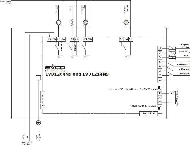
4.2Electric connection for models EVB1204N9 and EVB1214N9
The following drawing shows the electric connections for the EVB1204N9 and EVB1214N9 models.
page 16 of 88

EVCO S.p.A. |
EVBOX1 | Installation guide ver. 1.2 | Code 144BOX1E124 |
4.3Electric connection for models EVB1206N9 and EVB1216N9
The following drawing shows the electric connections for the EVB1206N9 and EVB1216N9 models.
page 17 of 88

EVCO S.p.A. |
EVBOX1 | Installation guide ver. 1.2 | Code 144BOX1E124 |
4.4Electric connection for models EVB1226N9 and EVB1236N9
The following drawing shows the electric connections for the EVB1226N9 and EVB1236N9 models.
page 18 of 88
EVCO S.p.A. |
EVBOX1 | Installation guide ver. 1.2 | Code 144BOX1E124 |
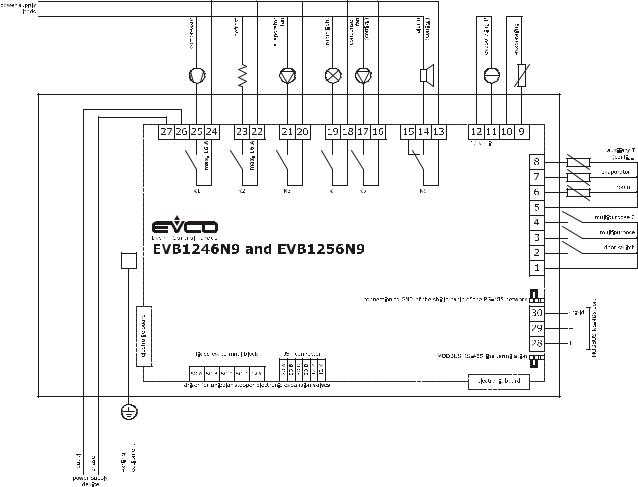
4.5Electric connection for models EVB1246N9 and EVB1256N9
The following drawing shows the electric connections for the EVB1246N9 and EVB1256N9 models.
page 19 of 88

EVCO S.p.A. |
EVBOX1 | Installation guide ver. 1.2 | Code 144BOX1E124 |
4.6Electric connection for models with magneto-thermal switch or differential
magneto-thermal circuit breaker (example for EVB1256N9D)
The following drawing shows the electric connections for models with magneto-thermal switch or differential magneto-thermal circuit breaker (example EVB1256N9D).
page 20 of 88
EVCO S.p.A. |
EVBOX1 | Installation guide ver. 1.2 | Code 144BOX1E124 |
4.7Insertion of the RS-485 MODBUS port termination resistor
To reduce reflections on the signal transmitted through the cables connecting the devices to a RS-485 network it is necessary to insert the termination resistor of the first and last elements of the network.
To insert the termination resistor place the jumper as shown in the following drawing.
4.8Connection of the RS-485 network cable screen to GND
To prevent external disturbances from being interpreted as signals by the RS-485 network, it might be necessary to connect the cable screen of the RS-485 network to GND
To connect the cable screen to GND, place the jumper as shown in the following drawing.
4.9Warnings for the electric connection
-do not use electric or pneumatic screwdrivers on the device terminal board
-if the device has been taken from a cold to hot place, humidity could condense inside; wait about 1 hour before powering it
-make sure that the power supply voltage, the frequency and the operational electric power of the device, correspond with those of the local power supply; see chapter “TECHNICAL DATA”
-disconnect the device power supply before proceeding with any type of maintenance
-connect the device to a RS-485 MODBUS network using a twisted pair
-position the power cables as far away as possible from the signal cables
-for repairs and information regarding the device, contact the EVCO sales network.
page 21 of 88
EVCO S.p.A. |
EVBOX1 | Installation guide ver. 1.2 | Code 144BOX1E124 |
5 FIRST USE
5.1First use
Operate as follows:
1.Install the device as described in chapter "DIMENSIONS AND INSTALLATION" , following in particular the instructions of paragraph “Installation warnings”.
2.Make the relevant electric connections for the device as shown in chapter "ELECTRIC CONNECTION", following in particular the instructions of paragraph “Warning for the electric connection", without connecting the device or the loads power supply.
3.Connect the device power supply: this shall launch an internal test.
The test typically takes a few seconds to complete; at the end of the test, the display turns off.
4.If, at the end of the test, the letters "rtc" flash on the screen and the buzzer sounds intermittently, it will be necessary to set the date, time and day of the week; please refer to paragraph 12.1 “Setting the date, time and day of the week (only in the models with clock)”.
5.Configure the device using the procedure described in paragraph “Setting the configuration parameters”,
The following table shows the meaning of the main configuration parameters; the parameters are shown in the order with which it is best to configure the device.
|
PARAM. |
MEANING |
DEFAULT SETTINGS |
|
||
|
|
|
|
|
|
|
|
|
temperature probe type |
|
|
||
|
P0 |
0 |
= |
PTC |
1 |
|
|
|
1 |
= |
NTC |
|
|
|
|
|
|
|
||
|
|
temperature unit of measurement |
|
|
||
|
P2 |
0 |
= |
°C |
0 |
|
|
|
1 |
= |
°F |
|
|
|
|
|
|
|
||
|
P9 |
pressure transducer minimum setting |
5 |
|
||
|
|
|
|
|
||
|
P10 |
pressure transducer maximum setting |
80 |
|
||
|
|
|
|
|
||
|
|
position of the pressure decimal point |
|
|
||
|
P11 |
0 |
= |
no decimal points |
1 |
|
|
|
1 |
= on the tens digit |
|
|
|
|
|
|
|
|||
|
SP |
work set-point |
-18,0 °C |
|||
|
|
|
|
|||
|
r0 |
working set-point differential |
2.0 °C |
|||
|
|
|
|
|
||
|
|
type of defrosting |
|
|
||
|
d0 |
0 |
= |
electric |
0 |
|
|
1 |
= |
by hot gas |
|
||
|
|
|
|
|||
|
|
2 |
= via stopping of compressor |
|
|
|
|
|
|
|
|||
|
d3 |
maximum defrosting duration |
30 min |
|||
|
|
|
|
|
|
|
page 22 of 88

EVCO S.p.A. EVBOX1 | Installation guide ver. 1.2 | Code 144BOX1E124
|
in the EVB1204N9 and EVB1214N9 models, the application is managed through |
|
|||
|
the K4 digital output |
|
|||
|
0 |
= man in cold room exit |
|
||
|
1 |
= |
demister heating elements |
|
|
|
2 |
= |
auxiliary output |
|
|
|
3 |
= |
alarm output |
|
|
|
4 |
= |
door heating elements |
|
|
u1 |
5 |
= |
neutral area operating heating elements |
0 |
|
|
6 |
= |
condenser fan |
|
|
|
7 |
= |
compressor 2 |
|
|
|
8 |
= |
defrosting2 |
|
|
|
9 |
= |
evaporator fan 2 |
|
|
|
10 |
= |
pump down valve |
|
|
|
11 |
= |
on/stand-by |
|
|
|
12 |
= man in cold room exit |
|
||
|
|
|
|||
|
in the remaining models, the application is managed by the K5 digital output |
|
|||
|
0 |
= |
reserved |
|
|
|
1 |
= |
demister heating elements |
|
|
|
2 |
= |
auxiliary output |
|
|
|
3 |
= |
alarm output |
|
|
|
4 |
= |
door heating elements |
|
|
u1 |
5 |
= neutral area operating heating elements |
5 |
||
6 |
= |
condenser fan |
|||
|
|
||||
|
7 |
= |
compressor 2 |
|
|
|
8 |
= |
defrosting2 |
|
|
|
9 |
= |
evaporator fan 2 |
|
|
|
10 |
= |
pump down valve |
|
|
|
11 |
= |
on/stand-by |
|
|
|
12 |
= man in cold room exit |
|
||
|
|
|
|||
|
if present, the application is managed by the K6 digital output |
|
|||
|
0 |
= |
reserved |
|
|
|
1 |
= |
demister heating elements |
|
|
|
2 |
= |
auxiliary output |
|
|
|
3 |
= |
alarm output |
|
|
|
4 |
= |
door heating elements |
|
|
u11 |
5 |
= neutral area operating heating elements |
2 |
||
6 |
= |
condenser fan |
|||
|
|
||||
|
7 |
= |
compressor 2 |
|
|
|
8 |
= |
defrosting2 |
|
|
9= evaporator fan 2
10= pump down valve
11= on/stand-by
12= man in cold room exit
Then, check that the remaining settings are appropriate; refer to paragraph 12.5 “List of configuration parameters”.
6.Connect the loads power supply
7.Turn the device on; refer to paragraph "Device switch-on/off in manual mode".
For additional information, please refer to the following paragraphs.
page 23 of 88

EVCO S.p.A. |
EVBOX1 | Installation guide ver. 1.2 | Code 144BOX1E124 |
6 USER INTERFACE
6.1Preliminary notes
Operating Statuses:
-“on” state (the device is powered and is on: the regulators can be switched on)
-“stand-by” status (the device is powered but is switched off via software: the regulators are switched off; the possibility to turn the room light or the auxiliary output on/off manually depends on parameter u2)
-the “off” status (the device is not powered).
Hereafter, with the word “start-up” means the passage from “stand-by” status to “on” status; the word “shutdown” means the passage from “on” status to “stand-by” status.
When the power is switched back on, the device displays the status that it was in at the time it was disconnected.
6.2Device switch-on/off in manual
mode
To turn the device on/off in manual mode, proceed as follows: 1. Make sure that the keyboard is not locked and that
no procedure is in progress.
2. Hold the key “ON/STAND-BY” for 2 s.
Using the digital inputs it is also possible to remotely switch on/off the device.
Device switch-on/off in manual mode
6.3The display
If the device is switched on, during normal operation, the display will show the magnitude established with P5, except during defrosting, when the device will show the temperature established with parameter d6.
If the device is switched off, the display will be switched off.
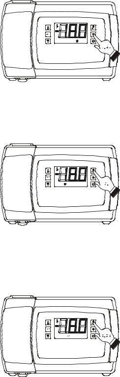
6.4 Displaying the magnitude detected by an analogue input
To display the magnitude detected by an analogue input, proceed as follows: 1. Make sure that the keyboard is not locked and that
no procedure is in progress.
2. Hold the key “DOWN” for 1 s: the display will show the first label available.
3. Press and release the key “UP” or “DOWN” to
select a label.
Access the procedure to display the quantity detected by an analogue input
page 24 of 88

EVCO S.p.A.
The following table shows the correspondence between the labels and the magnitudes displayed.
|
LABEL |
MAGNITUDE |
|
|
|
|
Pb1 |
room/inflowing air temperature; see also |
|
parameter P4 |
|
|
|
|
|
|
|
|
Pb2 |
evaporator temperature |
|
|
|
|
Pb3 |
auxiliary temperature; see also parameter P4 |
|
|
|
|
Pb4 |
CPT temperature; see also parameter P4 |
|
|
|
|
Pb5 |
if present, vapour pressure |
|
|
|
|
Pb6 |
if present, evaporation temperature |
|
|
|
4.Press and release the key “SET”.
To exit the procedure:
5.Press and release the key “SET” or do not operate for 60 sec.
6.Press and release the “UP” or “DOWN” key until the display shows the magnitude established with parameter P5 or do not operate for 60 sec.
Alternatively:
7.Press and release the “ON/STAND-BY” key.
If the evaporator temperature sensor is not present (or if the P3 parameter is set to 0), the "Pb2" label shall not be displayed.
If the auxiliary temperature sensor is not present (or if the P4 parameter is set to 0), the "Pb3" label shall not be displayed. If the magnitude recorded by the auxiliary sensor is not the outgoing air temperature (or if the P4 parameter is not set to 4) the "Pb4" label shall not be displayed.
EVBOX1 | Installation guide ver. 1.2 | Code 144BOX1E124
Displaying the magnitude detected by an analogue input
6.5 "Rapid cooling" function enabling/disabling
To enable/disable the "rapid cooling" function, proceed as follows:
1. |
Check that the device is turned on, that the |
|
|
keypad is not locked, that no procedures are in |
|
|
progress and that there are no defrosting, dripping |
|
|
or evaporator fan stop operations in progress. |
|
2. |
Keep the "UP" key |
pressed for 4 s: the |
"Rapid cooling" function enabling/disabling
"temperature" LED light shall start flashing.
page 25 of 88
EVCO S.p.A.
During the "rapid cooling" function the work set point is decreased by the temperature set with the r5 parameter; the function runs for the span of time set with the r6 parameter.
During the "rapid cooling" function the defrosting function is never activated; if the defrosting interval expires while the rapid cooling function is in progress, the defrosting shall be activated at the end of the cooling.
6.6Defrosting manual activation
To activate the defrosting in manual mode, proceed as follows:
1.Check that the device is turned on, that the keypad is not locked, that no procedures are in progress and that the "rapid cooling" function is not in progress.
2.Keep the "DEFROSTING" key pressed for 4 s.
If the evaporator temperature sensor functions as a defrosting sensor (that is to say,if the P3 parameter is set to 1) and when the defrosting starts the evaporator temperature exceeds the value set with the d2 parameter, the defrosting shall not be activated.
6.7 Turning on/off of room lights manually (only if the parameter u1 and/or parameter u11 is set at 0)
To turn the room light on/off in manual mode, proceed as follows:
1.Make sure no procedures are in progress.
2.Press and release the "AUXILIARY" key: the "room light" LED shall turn on/off.
Through the digital ports it is also possible to turn the room light on/off from remote; see parameter u2.
If parameter u1 and/or parameter u11 are set to 2 (that is to say, if the application managed by the K5 and/or K6 outputs is the auxiliary output), pressing the "AUXILIARY" key for 2 s shall make the "auxiliary 1" and/or "auxiliary 2" and the auxiliary output LEDs turn on/off.
EVBOX1 | Installation guide ver. 1.2 | Code 144BOX1E124
Defrosting manual activation
Turning on/off of room lights in manual mode
6.8 Turning the demister heating elements on/off manually (only if the parameter u1 and/or parameter u11 is set at 1)
To turn the demister heating elements on, proceed as follows: |
|
|
1. |
Check that the device is turned on and no |
|
|
procedures are in progress. |
Demister heating elements manual activation |
|
|
|
page 26 of 88
EVCO S.p.A.
2.Keep the "AUXILIARY" key pressed for 2 s: the "AUX1" and/or "AUX2" LEDs shall light up and the heating elements be turned turned on, both for the length of time set with the parameter u6.
The demister heating elements cannot be turned off in manual mode (that is to say, before the time set with the parameter u6 has expired).
6.9 Turning on/off of the auxiliary output manually (only if the parameter u1 and/or parameter u11 is set at 2)
To turn the auxiliary output on/off in manual mode, proceed as follows:
1.Make sure that the keyboard is not locked and that no procedure is in progress.
2.Keep the "AUXILIARY" key pressed for 2 s: the "AUX1" and/or "AUX2" LEDs shall turn on/off.
Through the digital ports it is also possible to turn the auxiliary output on/off from remote; see parameter u2.
If the auxiliary output has been turned on manually, it shall be possible to turn it off only in the same mode (similarly, if it was turned on from renote, it shall be possible to turn it off only from remote); see also parameter u2.
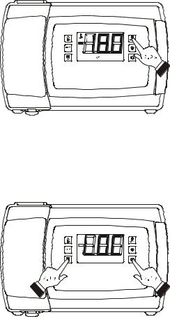
6.10Keyboard locking/unlocking
To lock the keyboard proceed as follows:
1.Check that the device is turned on and no procedures are in progress.
2.Keep the "DOWN" and "ON/STAND-BY" keys pressed for 1 s: the word "Loc" shall be displayed on screen for 1 s.
If the keyboard is locked, the following are not permitted:
-device switch-on/off in manual mode
-display of a magnitude recorded by an analogue input (with the procedure described in paragraph 6.4 “Displaying the magnitude detected by an analogue input”)
-activation/deactivation of “rapid cooling” function
-manual activation of defrosting
-manual switch on/off of the auxiliary output
-activation of the low or high relative humidity percentage operation mode to learn how it works
page 27 of 88
EVBOX1 | Installation guide ver. 1.2 | Code 144BOX1E124
Turning on/off of the auxiliary output manually
Keyboard locking
 Loading...