


EVCO S.p.A. |
VCOLOR 818 | Installer manual ver. 1.1 | Code 144VC818E114 |
VCOLOR 818
Controller for “top-class” blast chillers, with colour touch-screen TFT graphic display, in split version and which can be integrated into the unit
ENGLISH
INSTALLER MANUAL ver. 1.1
CODE 144VC818E114
page 1 of 94
EVCO S.p.A. VCOLOR 818 | Installer manual ver. 1.1 | Code 144VC818E114
Important
Important
Read this document thoroughly before installation and before use of the device and follow all recommendations; keep this document with the device for future consultation.
The following symbols support reading of the document:
indicates a suggestion
indicates a warning.
The device must be disposed of in compliance with local Standards regarding the collection of electric and electronic equipment.
page 2 of 94
EVCO S.p.A. VCOLOR 818 | Installer manual ver. 1.1 | Code 144VC818E114
Index
1 |
INTRODUCTION................................................................................................................................... |
5 |
|
1.1 |
Introduction ........................................................................................................................................ |
5 |
|
1.2 |
Summary table of the main features and the models available................................................................... |
6 |
|
2 |
DESCRIPTION...................................................................................................................................... |
8 |
|
2.1 |
Description of the user interface ............................................................................................................ |
8 |
|
2.2 |
Description of the control module........................................................................................................... |
9 |
|
3 |
DIMENSIONS AND INSTALLATION........................................................................................................ |
11 |
|
3.1 |
User interface dimensions ................................................................................................................... |
11 |
|
3.2 |
Control module dimensions ................................................................................................................. |
11 |
|
3.3 |
User interface installation.................................................................................................................... |
11 |
|
3.4 |
Control module installation.................................................................................................................. |
11 |
|
3.5 |
Installation warnings .......................................................................................................................... |
12 |
|
4 |
ELECTRIC CONNECTION...................................................................................................................... |
13 |
|
4.1 |
Electric connection ............................................................................................................................. |
13 |
|
4.2 |
Warnings for the electric connection..................................................................................................... |
14 |
|
5 |
USER INTERFACE............................................................................................................................... |
15 |
|
5.1 |
Foreword .......................................................................................................................................... |
15 |
|
5.2 |
Device commissioning ........................................................................................................................ |
15 |
|
5.3 |
Switching the device on/off ................................................................................................................. |
16 |
|
5.4 |
The display........................................................................................................................................ |
16 |
|
5.5 |
Display of inputs and outputs status..................................................................................................... |
18 |
|
5.6 |
Defrosting activation in manual mode................................................................................................... |
19 |
|
5.7 |
Locking/unlocking of the keyboard ....................................................................................................... |
19 |
|
5.8 |
Silencing the buzzer ........................................................................................................................... |
20 |
|
6 |
OPERATION....................................................................................................................................... |
21 |
|
6.1 |
Foreword .......................................................................................................................................... |
21 |
|
6.1.1 |
Foreword regarding needle probe ................................................................................................. |
21 |
|
6.2 |
Temperature-controlled blast chilling and storage .................................................................................. |
22 |
|
6.3 Temperature-controlled hard blast chilling and storage............................................................................... |
24 |
||
6.4 |
Time-controlled blast chilling and storage.............................................................................................. |
26 |
|
6.5 |
Time-controlled hard blast chilling and storage ...................................................................................... |
28 |
|
6.6 |
Continuous blast chilling ..................................................................................................................... |
30 |
|
6.7 |
Temperature-controlled deep freezing and storage................................................................................. |
31 |
|
6.8 |
Temperature-controlled soft deep freezing and storage........................................................................... |
34 |
|
6.9 |
Time-controlled deep freezing and storage............................................................................................ |
36 |
|
6.10 |
|
Time-controlled soft deep freezing and storage.................................................................................. |
38 |
6.11 |
|
Continuous deep freezing................................................................................................................ |
40 |
6.12 |
|
Blast chilling/deep freezing intensity................................................................................................. |
42 |
6.12.1 Selecting the evaporator fan speed............................................................................................... |
44 |
||
6.13 |
|
Pre-cooling start-up........................................................................................................................ |
45 |
6.14 |
|
Test for verification of the correct insertion of the needle probe ........................................................... |
46 |
6.15 |
|
Switching on UV light for sterilisation cycle........................................................................................ |
46 |
6.16 |
|
Heating the needle probe ................................................................................................................ |
47 |
6.17 |
|
Fish sanification ............................................................................................................................. |
48 |
6.18 |
|
Data print-out................................................................................................................................ |
50 |
7 |
“PROGRAMS” FUNCTION..................................................................................................................... |
51 |
|
7.1 |
Foreword .......................................................................................................................................... |
51 |
|
page 3 of 94
EVCO S.p.A. VCOLOR 818 | Installer manual ver. 1.1 | Code 144VC818E114
7.2 |
Memorisation of a program ................................................................................................................. |
51 |
|
7.3 |
Execution of a program....................................................................................................................... |
52 |
|
8 |
“FAVOURITES” FUNCTION................................................................................................................... |
53 |
|
8.1 |
Foreword .......................................................................................................................................... |
53 |
|
8.2 |
Execution of a program....................................................................................................................... |
53 |
|
9 |
“HACCP” FUNCTION............................................................................................................................ |
54 |
|
9.1 |
Foreword .......................................................................................................................................... |
54 |
|
9.2 |
Display of information relative to the HACCP alarms............................................................................... |
55 |
|
9.3 |
Deleting the information relative to the HACCP alarms............................................................................ |
56 |
|
10 |
COMPRESSOR OPERATING HOURS COUNT............................................................................................ |
57 |
|
10.1 |
|
Display of compressor operating hours.............................................................................................. |
57 |
11 |
CONFIGURATION ............................................................................................................................... |
58 |
|
11.1 |
|
Setting the real day and time .......................................................................................................... |
58 |
11.2 |
|
Setting the configuration parameters................................................................................................ |
59 |
11.3 |
|
Restoring the factory settings .......................................................................................................... |
60 |
11.3.1 Access to the procedure .............................................................................................................. |
60 |
||
11.3.2 Restoring the configuration parameters......................................................................................... |
60 |
||
11.3.3 |
Deleting programs...................................................................................................................... |
61 |
|
11.3.4 |
Deleting favourites ..................................................................................................................... |
61 |
|
11.3.5 Deleting the compressor operating hours....................................................................................... |
62 |
||
11.4 |
|
List of configuration parameters....................................................................................................... |
63 |
12 |
USE OF THE USB PORT....................................................................................................................... |
76 |
|
12.1 |
|
Foreword....................................................................................................................................... |
76 |
12.2 |
|
Upload and download of the configuration parameters ........................................................................ |
76 |
12.3 |
|
Upload and download of the programs .............................................................................................. |
77 |
12.4 |
|
Download of the information relative to the HACCP alarms .................................................................. |
79 |
13 |
ALARMS............................................................................................................................................ |
81 |
|
13.1 |
|
Alarms.......................................................................................................................................... |
81 |
14 |
ERRORS............................................................................................................................................ |
83 |
|
14.1 |
|
Errors ........................................................................................................................................... |
83 |
15 |
ACCESSORIES ................................................................................................................................... |
85 |
|
15.1 |
|
Phase cut speed regulator for single phase fans EVDFAN1 ................................................................... |
85 |
15.1.1 |
Introduction............................................................................................................................... |
85 |
|
15.1.2 |
Description................................................................................................................................ |
85 |
|
15.1.3 |
Dimensions................................................................................................................................ |
86 |
|
15.1.4 Connection to the device ............................................................................................................. |
86 |
||
15.2 |
|
Print module PM 100A X9S001......................................................................................................... |
86 |
15.2.1 |
Introduction............................................................................................................................... |
86 |
|
15.2.2 |
Description................................................................................................................................ |
86 |
|
15.2.3 |
Dimensions................................................................................................................................ |
87 |
|
15.2.4 Connection to the device ............................................................................................................. |
88 |
||
16 |
TECHNICAL DATA............................................................................................................................... |
89 |
|
16.1 |
|
Technical data ............................................................................................................................... |
89 |
page 4 of 94
EVCO S.p.A. |
VCOLOR 818 | Installer manual ver. 1.1 | Code 144VC818E114 |
1INTRODUCTION
1.1Introduction
VCOLOR 818 is a controller with elegant design for the management of “top-class” blast chillers.
It is available in split version and can be integrated both mechanically and aesthetically in the unit; the user interface consists of a colour touch-screen TFT graphic display and guarantees an IP65 protection rating, for easy cleaning.
The controller is able to manage positive and negative blast chilling cycles (with intensity management), both temperature and time controlled (with “hard/soft” function); the temperature controlled cycles can be preceded by a test to verify the proper insertion of the needle probe (with management of “multipoint” probes).
It also has the real time clock (to store the HACCP alarms), the “programs” function (to store the blast chilling settings in a program to be selected and run later on) and a USB communication port (to allow the upload and the download of the settings and the data recorded by the controller, through a common USB flash drive).
Installation is by back-panel, with threaded studs (in this case it guarantees no thickness) or by panel (from the front), with self-threading screws and frame (in this case it needs less depth).
page 5 of 94
EVCO S.p.A. |
VCOLOR 818 | Installer manual ver. 1.1 | Code 144VC818E114 |
1.2Summary table of the main features and the models
available
The following table illustrates the main features of the device.
“ / “ indicates the feature can be set via a configuration parameter.
|
User interface (open frame) |
|
VCOLOR 818 |
|
|
|
|
|
128.0 x 94.5 mm (5.039 x 3.720 in; L x H) |
|
• |
|
|
|
|
|
TFT graphic display 3.5 (inch) touch-screen with 16 colors |
|
• |
|
and 240 x 320 pixel resolution |
|
|
|
|
|
|
|
|
|
|
|
Control module (open frame) |
|
VCOLOR 818 |
|
|
|
|
|
166.0 x 116.0 mm (6.535 x 4.566 in; L x H) |
|
• |
|
|
|
|
|
Connections |
|
VCOLOR 818 |
|
|
|
|
|
removable screws terminal board |
|
• |
|
|
|
|
|
Power supply |
|
VCOLOR 818 |
|
|
|
|
|
115... 230 VAC |
|
• |
|
|
|
|
|
Analogue inputs |
|
VCOLOR 818 |
|
|
|
|
|
cabinet probe |
|
PTC/NTC |
|
|
|
|
|
needle probe 1 |
|
PTC/NTC |
|
|
|
|
|
needle probe 2 |
|
PTC/NTC |
|
|
|
|
|
needle probe 3 |
|
PTC/NTC |
|
|
|
|
|
evaporator probe |
|
PTC/NTC |
|
|
|
|
|
condenser probe |
|
PTC/NTC |
|
|
|
|
|
Digital inputs (for NO/NC contact) |
|
VCOLOR 818 |
|
|
|
|
|
door micro switch |
|
• |
|
|
|
|
|
compressor circuit breaker protection |
|
• |
|
|
|
|
|
low pressure |
|
• |
|
|
|
|
|
high pressure |
|
• |
|
|
|
|
|
page 6 of 94 |
|
|
EVCO S.p.A. VCOLOR 818 | Installer manual ver. 1.1 | Code 144VC818E114
Analogue outputs (PWM) |
|
VCOLOR 818 |
|
|
|
|
|
evaporator fan |
(1) |
|
|
|
|
|
|
Digital outputs (electromechanical relays; A res. @ |
|
VCOLOR 818 |
|
|
|
|
|
250 VAC) |
|
|
|
|
|
|
|
compressor |
|
16 A |
|
|
|
|
|
defrosting |
|
8 A |
|
|
|
|
|
evaporator fan |
|
8 A |
|
|
|
|
|
condenser fan |
|
8 A |
|
|
|
|
|
door heating elements |
|
8 A |
|
|
|
|
|
needle probe heating |
|
16 A |
|
|
|
|
|
load 7 (default room light) (1) |
|
8 A |
|
|
|
|
|
load 8 (default pump down valve) (2) |
|
8 A |
|
|
|
|
|
Communication port |
|
VCOLOR 818 |
|
|
|
|
|
RS-485 serial port with MODBUS communication protocol |
|
• |
|
|
|
|
|
USB serial port |
|
• |
|
|
|
|
|
Other features |
|
VCOLOR 818 |
|
|
|
|
|
protection rating of the user interface |
|
IP65 |
|
|
|
|
|
clock |
|
• |
|
|
|
|
|
alarm buzzer |
|
• |
|
|
|
|
|
hard / soft function |
|
• |
|
|
|
|
|
“programs” function |
|
• |
|
|
|
|
|
“HACCP” function |
|
• |
|
|
|
|
|
Notes:
(1)Configurable for dehumidifier or condenser fan.
(2)Configurable for pump down valve or evaporator fan.
For further information, see chapter "TECHNICAL DATA"; for other models contact the EVCO sales network.
page 7 of 94

EVCO S.p.A. |
VCOLOR 818 | Installer manual ver. 1.1 | Code 144VC818E114 |
2DESCRIPTION
2.1Description of the user interface
The following drawing illustrates the aspect of the VCOLOR 818 user interface.
The following table illustrates the meaning of VCOLOR 818 user interface parts.
Part Meaning
1 Interactive keys and display
2USB serial port
For further information, see the next chapters.
page 8 of 94
EVCO S.p.A. |
VCOLOR 818 | Installer manual ver. 1.1 | Code 144VC818E114 |
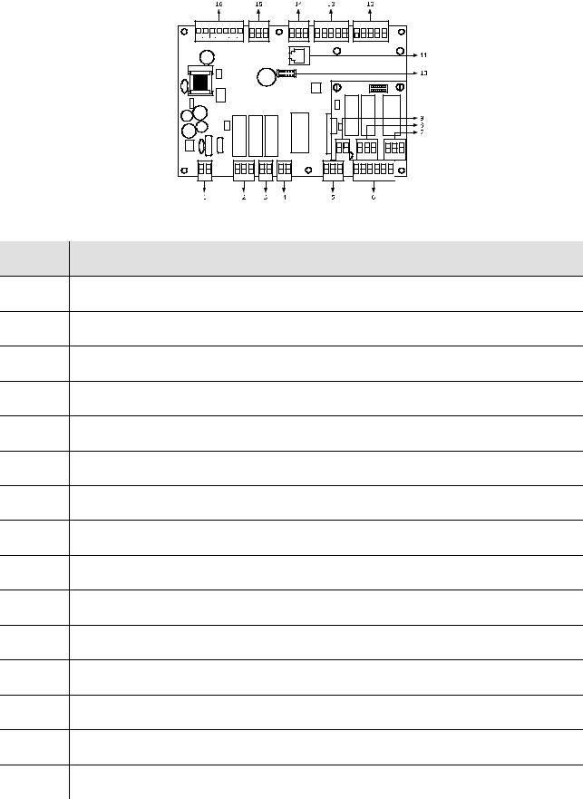
2.2Description of the control module
The following drawing illustrates the aspect of the VCOLOR 818 control module.
The following table illustrates the meaning of the VCOLOR 818 control module parts.
Part Meaning
1power supply
2 digital outputs K3 and K4
3 digital output K2
4 digital output K1
5 digital output K5
6digital inputs
7digital output K6
8digital outputs K7 and K8
9reserved
10reserved
11reserved
12analog inputs (cabinet probe, evaporator probe and condenser probe)
13analog inputs (needle probe 1, needle probe 2 and needle probe 3)
14reserved
15PWM analogue output
page 9 of 94

EVCO S.p.A. |
VCOLOR 818 | Installer manual ver. 1.1 | Code 144VC818E114 |
16 communication port with the user interface (signal and power supply)
For further information, see the next chapters.
page 10 of 94

EVCO S.p.A. |
VCOLOR 818 | Installer manual ver. 1.1 | Code 144VC818E114 |
3DIMENSIONS AND INSTALLATION
3.1User interface dimensions
The following drawing illustrates the VCOLOR 818 user interface dimensions; these are expressed in mm (in).
3.2Control module dimensions
The following drawing illustrates the VCOLOR 818 control module dimensions; these are expressed in mm (in).
3.3User interface installation
Back panel, with threaded studs (in this case it guarantees no thickness) or by panel (from the front), with selfthreading screws and frame (in this case it needs less depth).
3.4Control module installation
On flat surface, with spacers.
page 11 of 94
EVCO S.p.A. |
VCOLOR 818 | Installer manual ver. 1.1 | Code 144VC818E114 |
3.5Installation warnings
-make sure that the device work conditions (temperature of use, humidity, etc.) lie within the limits indicated; see chapter 16 "TECHNICAL DATA"
-do not install the device near to any heat sources (heating elements, hot air ducts etc.), equipment containing powerful magnets (large diffusers, etc), areas affected by direct sunlight, rain, humidity, excessive dust, mechanical vibrations or shocks.
-any metal parts in proximity of the control module must be at a distance such that they do not compromise the safety distances; possible wirings must be located at 2 cm (0.787 in) at least
-in compliance with Safety Standards, the device must be installed correctly and in a way to protect against any contact with electric parts; all parts that ensure protection must be fixed in a way that they cannot be removed without the use of tools.
page 12 of 94

EVCO S.p.A. |
VCOLOR 818 | Installer manual ver. 1.1 | Code 144VC818E114 |
4ELECTRIC CONNECTION
4.1Electric connection
The following drawing illustrates the VCOLOR 818 electric connection.
The utility managed by the K7 output, depends on parameter u11, as follows:
-cabinet light (u11 = 0, pre-defined setting)
-UV light (u11 = 1).
For the settings relative to the parameters, see chapter 11 “CONFIGURATION”.
The utility managed by the K8 output, depends on parameter u1, as follows:
-pump down valve (u1 = 0, pre-defined setting)
-alarm (u1 = 1).
For the settings relative to the parameters, see chapter 11 “CONFIGURATION”.
page 13 of 94

EVCO S.p.A. |
VCOLOR 818 | Installer manual ver. 1.1 | Code 144VC818E114 |
The RS-485 port is for the connection of the controller to the following additional products:
-Parameters Manager set-up software system
-Plant monitoring and supervision system via Internet: CLOUDEVOLUTION
-printing module PM 100A X9S001.
The port must not be used simultaneously with more than one of these products.
4.2Warnings for the electric connection
-do not use electric or pneumatic screwdrivers on the device terminal board
-if the device has been taken from a cold to hot place, humidity could condense inside; wait about 1 hour before powering it
-make sure that the power supply voltage, the frequency and the operational electric power of the device, correspond with those of the local power supply; see chapter 16 "TECHNICAL DATA"
-disconnect the device power supply before proceeding with any type of maintenance
-do not use this device as a safety device
-for repairs and information regarding the device, contact the EVCO sales network.
page 14 of 94

EVCO S.p.A. |
VCOLOR 818 | Installer manual ver. 1.1 | Code 144VC818E114 |
5USER INTERFACE
5.1Foreword
The following operating status exist:
-the “off” status (the device is not powered)
-the “stand-by” status (the device is powered and is off)
-the “on” status (the device is powered, is on and is in stand-by for the start-up of an operating cycle)
-the “run” status (the device is powered, is on and an operating cycle is in progress).
Hereon, the term "device switch-on" means the passage from the "stand-by" status to the "on" status. the term "switch-off" means passage from the "on" status to the "stand-by" status.
If a power cut occurs during the "stand-by" status or during the "on" status, the device will re-propose the same status when the power supply is restored.
If a power cut occurs during the "run" status, the device will operate as follows when this is restored:
-if a temperature-controlled blast chilling or deep freezing operation was in progress, these will be started again from the beginning
-if a timed-controlled blast chilling or deep freezing operation was in progress, these will be started again from the moment the power supply was cut-off
-if storage was in progress, this will be re-proposed.
5.2Device commissioning
Operate as follows:
1.Connect the device power supply. if parameter E9 is set at 1, the device will display the EVCO splash screen for 10 s;
2.After which it will go to the “stand-by” status.
page 15 of 94

EVCO S.p.A. |
VCOLOR 818 | Installer manual ver. 1.1 | Code 144VC818E114 |
3. Press and release the ON/STAND-BY key (1) and then press the highest interactive key on the left (2) to unlock the keyboard.
4.Press and release the ON/STAND-BY (1) key.
If the duration of the power cut has been such to cause the clock error (“rtc” code), the real day and time will have to be reset; see paragraph 11.1 “Setting the real day and time”.
5.3Switching the device on/off
Operate as follows:
1.Make sure that the keyboard is not locked and that no procedure is in progress.
2.Press and release the ON/STAND-BY key.
5.4The display
During the “stand-by” status the display show the real day and time.
During the “on” status, the device will display the real day and time and the temperature of the cabinet.
page 16 of 94

EVCO S.p.A. |
|
VCOLOR 818 | Installer manual ver. 1.1 | Code 144VC818E114 |
|||
|
|
|
|
|
|
|
|
|
|
|
|
|
|
|
|
|
|
|
|
|
|
|
|
|
|
|
|
|
|
During the "run" state the device will display:
-if a temperature-controlled blast chilling or deep freezing operation is in progress, the temperature detected by the needle probe, the temperature of the cabinet, the name of the program, (if envisioned) and the time passed from the start of blast chilling or deep freezing.
-if a time-controlled blast chilling or deep freezing operation is in progress, the residual duration of the blast chilling or deep freezing, the temperature of the cabinet, the name of the program, (if envisioned) and the time passed from the start of blast chilling or deep freezing
page 17 of 94
EVCO S.p.A. |
VCOLOR 818 | Installer manual ver. 1.1 | Code 144VC818E114 |
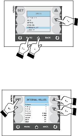
5.5Display of inputs and outputs status
Operate as follows:
1.Make sure that the instrument is in the “on” status.
2.Make sure that the keyboard is not locked and that no procedure is in progress.
3.Press and release the HOME key (1), press and release the MENU key (2) and then press and release the key repeatedly (3) in order to select the “INTERNAL VALUES”.
4.Press and release the SET key (4) and then repeatedly press and release the key (5) or the key (6) to select the input or the output.
Operate as follows to exit the procedure:
5.Press and release the ESCAPE key or do not operate for 60 s.
page 18 of 94

EVCO S.p.A. |
VCOLOR 818 | Installer manual ver. 1.1 | Code 144VC818E114 |
5.6Defrosting activation in manual mode
Operate as follows:
1.Make sure the device is in the "on" status, that pre-cooling or storage cycle is in progress.
2.Make sure that the keyboard is not locked and that no procedure is in progress.
3.Press and release the key (1), press and release the key (2) and then press and release the START/STOP (3) key.
If the evaporator probe is enabled, i.e. the parameter P4 is set at 1 and on activation of defrosting the evaporator temperature is above that established with parameter d2, defrosting will not be activated.
5.7Locking/unlocking of the keyboard
Operate as follows to lock the keyboard:
1.Make sure parameter E8 is set to 1 and no procedures are in progress.
2.Press and release the ON/STAND-BY key (1) and then press the highest interactive key on the left (2).
If parameter E8 is set to 2, on expiry of 60 s the keybord will automatically lock.
Operate as follows to unlock the keyboard:
1.Make sure no procedures are in progress
2.Press and release the ON/STAND-BY key (1) and then press the highest interactive key on the left (2).
page 19 of 94

EVCO S.p.A. |
|
|
|
|
VCOLOR 818 | Installer manual ver. 1.1 | Code 144VC818E114 |
||
|
|
|
|
|
|
|
|
|
|
|
|
|
|
|
|
|
|
|
|
|
|
|
|
|
|
|
|
|
|
|
|
|
|
|
|
|
|
|
|
|
|
|
|
|
|
|
|
|
|
|
|
|
|
|
|
|
|
|
|
|
|
|
|
|
|
|
|
|
|
|
|
5.8Silencing the buzzer
Operate as follows:
1.Make sure no procedures are in progress
2.Press and release the key.
page 20 of 94
EVCO S.p.A. |
VCOLOR 818 | Installer manual ver. 1.1 | Code 144VC818E114 |
6OPERATION
6.1Foreword
The device can manage the following operating cycles:
-temperature-controlled blast chilling and storage
-temperature-controlled hard blast chilling and storage
-time-controlled blast chilling and storage
-time-controlled hard blast chilling and storage
-continuous blast chilling
-temperature-controlled deep freezing and storage
-temperature-controlled soft deep freezing and storage
-time-controlled deep freezing and storage
-time-controlled soft deep freezing and storage
-continuous deep freezing
For further information, see the next paragraphs
Every operating cycle can be preceded by pre-cooling; see paragraph 6.13 "Pre-cooling start-up".
The temperature-controlled cycles are preceded by a test to verify the correct insertion of the needle probe; see paragraph 6.14 " Management of the test regarding correct insertion of the needle probe".
If the needle probe is not enabled, i.e. if parameter P3 is set at 0, the temperature-controlled cycles will be started with time-control.
The following functions can also be used:
-switching on sterilisation cycle UV light
-heating the needle probe.
For further information, see the next paragraphs
6.1.1Foreword regarding needle probe
The device can manage "multipoint" needle probes (with up to three sensors".
Parameter P3 establishes the number of needle probe sensors as indicated:
-if parameter P3 is set at 0, the needle probe will not be enabled
-if parameter P3 is set at 1, there will be one sensor (needle probe 1)
-if parameter P3 is set at 2, there will be 2 sensors (needle probe 1 and needle probe 2)
-if parameter P3 is set at 3, there will be 3 sensors (needle probe 1 and needle probe 2 and needle probe 3).
If parameter P3 is set at values different to 0, the temperature-controlled cycles will be preceded by a test to verify the correct insertion of the needle probe; see paragraph 6.14 " Management of the test regarding correct insertion of the needle probe".
On conclusion of the test, the device will operate as indicated:
-the sensor that has detected the lowest temperature is then used as the reference temperature for heating the needle probe.
-the sensor that has detected the highest temperature is then used as the reference for the temperaturecontrolled cycles
-the sensors for which the test is not completed successfully are not used successively.
page 21 of 94
EVCO S.p.A. |
VCOLOR 818 | Installer manual ver. 1.1 | Code 144VC818E114 |
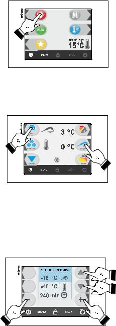
6.2Temperature-controlled blast chilling and storage
The temperature-controlled blast chilling and storage cycle is divided into the following two phases:
-blast chilling
-storage.
On conclusion of a phase, the device passes automatically to the next.
Operate as indicated to start the cycle:
1.Make sure the device is in the "on" status.
2.Make sure that the keyboard is not locked and that no procedure is in progress.
3.Press and release the key (1);
4.Press and release the key (2) and then press and release the key (3). the device will display the blast chilling end temperature and the work set-point during blast chilling.
4.1Press and release the MENU key and then press and release the key (4) or the key (5) to select the blast chilling end temperature and the work set-point during blast chilling.
4.2Press and release the key + (6) or the key – (7) to modify these values and then the ESCAPE key to memorise them; these values can also be memorised through parameters r3 and r7.
5.Press and release the START/STOP key (1): the test to verify the correct insertion of the needle probe will be started; see paragraph 6.14 " Test for verification of the correct insertion of the needle probe".
page 22 of 94

EVCO S.p.A. |
VCOLOR 818 | Installer manual ver. 1.1 | Code 144VC818E114 |
5.1If the test is completed successfully, the cycle will be started.
The maximum blast chilling duration count is started on condition that the temperature detected by the needle probe is below that established with parameter r15.
5.2If the test is not completed successfully, the buzzer will be activated for 5 s every 60 s and the cycle will
be started with timed-control; see paragraph 6.4 "Time-controlled blast chilling and storage".
During blast chilling the device displays the temperature detected by the needle probe, the cabinet temperature, the program name (if envisioned) and the time passed since the start of blast chilling.
Operate as indicated to stop the cycle:
6.Press and hold the START/STOP key 3 s.
The successive parameters establish the following values:
-parameter r3 establishes the blast chilling end temperature
-parameter r5 establishes the maximum blast chilling duration
-parameter r7 establishes the work set-point during blast chilling.
If the temperature detected by the needle probe reaches the blast chilling end temperature within the maximum blast chilling duration, it means that blast chilling has been completed successfully, the device will automatically pass to storage and the buzzer will be activated for the period of time established with parameter AA.
Press and release a key to silence the buzzer.
During storage the device displays the temperature of the cabinet, the program name (if envisioned) and the time taken to complete blast chilling successfully.
Parameter r10 establishes the work set-point during storage.
If the temperature detected by the needle probe does not reach the blast chilling end temperature within the maximum blast chilling duration, blast chilling will not be completed successfully but will continue and the buzzer will be activated. Press and release a key to restore normal display and to silence the buzzer.
When the temperature detected by the needle probe reaches the blast chilling end temperature, the device automatically passes to storage in the same way as illustrated previously.
page 23 of 94

EVCO S.p.A. |
|
VCOLOR 818 | Installer manual ver. 1.1 | Code 144VC818E114 |
|||
|
|
|
|
|
|
|
|
|
|
|
|
|
|
|
|
|
|
|
|
|
|
|
|
|
|
|
|
|
|
|
|
|
|
|
|
6.3Temperature-controlled hard blast chilling and storage
The temperature-controlled hard blast chilling and storage cycle is divided into the following three phases:
-blast chilling hard phase
-blast chilling
-storage.
On conclusion of a phase, the device passes automatically to the next.
Operate as indicated to start the cycle:
1.Make sure the device is in the "on" status.
2.Make sure that the keyboard is not locked and that no procedure is in progress.
3.Press and release the key (1), press and release the key (2) and then press and release the key (3) and finally press and release the key (4): the device will display the blast chilling end temperature and the work set-point during blast chilling.
4.1Press and release the MENU key and then press and release the key (4) or the key (5) to select the blast chilling end temperature and the work set-point during blast chilling.
4.2Press and release the key + (6) or the key – (7) to modify these values and then the ESCAPE key to memorise them; these values can also be memorised through parameters r3 and r7.
page 24 of 94

EVCO S.p.A. |
|
VCOLOR 818 | Installer manual ver. 1.1 | Code 144VC818E114 |
||
|
|
|
|
|
|
|
|
|
|
|
|
|
|
|
|
|
|
|
|
|
|
|
|
|
5.Press and release the START/STOP key (1): the test to verify the correct insertion of the needle probe will be started; see paragraph 6.14 " Test for verification of the correct insertion of the needle probe".
5.1If the test is completed successfully, the cycle will be started.
The maximum blast chilling duration count is started on condition that the temperature detected by the needle probe is below that established with parameter r15.
5.2If the test is not completed successfully, the buzzer will be activated for 5 s every 60 s and the cycle will be started with timed-control; see paragraph 6.4 "Time-controlled hard blast chilling and storage".
During hard blast chilling phase the device displays the temperature detected by the needle probe, the cabinet temperature, the program name (if envisioned) and the time passed since the start of blast chilling .
Operate as indicated to stop the cycle:
6.Press and hold the START/STOP key 3 s.
The successive parameters establish the following values:
-parameter r5 establishes the maximum blast chilling duration
-parameter r9 establishes the work set-point during the blast chilling hard phase
-parameter r13 establishes blast chilling hard phase end temperature.
When the temperature detected by the needle probe reaches the hard blast chilling phase end temperature, the device automatically passes to blast chilling mode.
During blast chilling the device displays the temperature detected by the needle probe, the cabinet temperature, the program name (if envisioned) and the time passed since the start of blast chilling.
The successive parameters establish the following values:
-parameter r3 establishes the blast chilling end temperature
-parameter r5 establishes the maximum blast chilling duration
-parameter r7 establishes the work set-point during blast chilling.
If the temperature detected by the needle probe reaches the blast chilling end temperature within the maximum blast chilling duration, it means that blast chilling has been completed successfully, the device will automatically pass to storage and the buzzer will be activated for the period of time established with parameter AA.
Press and release a key to silence the buzzer.
During storage the device displays the temperature of the cabinet, the program name (if envisioned) and the time taken to complete blast chilling successfully.
page 25 of 94

EVCO S.p.A. |
|
VCOLOR 818 | Installer manual ver. 1.1 | Code 144VC818E114 |
|||
|
|
|
|
|
|
|
|
|
|
|
|
|
|
|
|
|
|
|
|
|
|
|
|
|
|
|
|
|
|
|
|
|
|
|
|
Parameter r10 establishes the work set-point during storage.
If the temperature detected by the needle probe does not reach the blast chilling end temperature within the maximum blast chilling duration, blast chilling will not be completed successfully but will continue and the buzzer will be activated.
Press and release a key to restore normal display and to silence the buzzer.
When the temperature detected by the needle probe reaches the blast chilling end temperature, the device automatically passes to storage in the same way as illustrated previously.
6.4Time-controlled blast chilling and storage
The time-controlled blast chilling and storage cycle is divided into the following two phases:
-blast chilling
-storage.
On conclusion of a phase, the device passes automatically to the next.
Operate as indicated to start the cycle:
1.Make sure the device is in the "on" status.
2.Make sure that the keyboard is not locked and that no procedure is in progress.
3.Press and release the key (1) and then press and release the key (2): the device will display the blast chilling duration and the work set-point during blast chilling.
page 26 of 94

EVCO S.p.A. |
|
VCOLOR 818 | Installer manual ver. 1.1 | Code 144VC818E114 |
||
|
|
|
|
|
|
|
|
|
|
|
|
|
|
|
|
|
|
|
|
4.1Press and release the MENU key and then press and release the key (4) or the key (5) to select the blast chilling duration and the work set-point during blast chilling.
4.2Press and release the key + (6) or the key – (7) to modify these values and then the ESCAPE key to memorise them; these values can also be memorised through parameters r1 and r7.
5.Press and release the START/STOP key (1): the cycle will be started.
During blast chilling the device displays the residual blast chilling time, the temperature of the cabinet, the name of the program (if envisioned) and the time passed from the start of blast chilling.
Operate as indicated to stop the cycle:
6.Press and hold the START/STOP key 3 s.
The successive parameters establish the following values:
-parameter r1 establishes blast chilling duration
-parameter r7 establishes the work set-point during blast chilling.
On expiry of the blast chilling duration, the device automatically passes to storage mode and the buzzer is activated for the time period established with parameter AA.
Press and release a key to silence the buzzer.
page 27 of 94

EVCO S.p.A. |
VCOLOR 818 | Installer manual ver. 1.1 | Code 144VC818E114 |
During storage the device displays the temperature of the cabinet, the program name (if envisioned) and the duration of blast chilling.
Parameter r10 establishes the work set-point during storage.
6.5Time-controlled hard blast chilling and storage
The time-controlled hard blast chilling and storage cycle is divided into the following three phases:
-blast chilling hard phase
-blast chilling
-storage.
On conclusion of a phase, the device passes automatically to the next.
Operate as indicated to start the cycle:
1.Make sure the device is in the "on" status.
2.Make sure that the keyboard is not locked and that no procedure is in progress.
3.Press and release the key (1), press and release the key (2) and then press and release the key (3). the device will display the blast chilling duration and the work set-point during blast chilling.
4.1Press and release the MENU key and then press and release th key (4) or the key (5) to select the blast chilling duration and the work set-point during blast chilling.
page 28 of 94

EVCO S.p.A. |
VCOLOR 818 | Installer manual ver. 1.1 | Code 144VC818E114 |
4.2Press and release the key + (6) or the key – (7) to modify these values and then the ESCAPE key to memorise them; these values can also be memorised through parameters r1 and r7.
5.Press and release the START/STOP key (1): the cycle will be started.
During hard blast chilling the device displays the residual blast chilling time, the temperature of the cabinet, the name of the program (if envisioned) and the time passed from the start of blast chilling.
Operate as indicated to stop the cycle:
6.Press and hold the START/STOP key 3 s.
The successive parameters establish the following values:
-parameter r9 establishes the work set-point during the blast chilling hard phase
-parameter r14 establishes blast chilling hard phase duration.
On expiry of the hard blast chilling phase duration, the device automatically passes to blast chilling.
During blast chilling the device displays the residual blast chilling time, the temperature of the cabinet, the name of the program (if envisioned) and the time passed from the start of blast chilling.
The successive parameters establish the following values:
-parameter r1 establishes blast chilling duration
-parameter r7 establishes the work set-point during blast chilling.
On expiry of the blast chilling duration, the device automatically passes to storage mode and the buzzer is activated for the time period established with parameter AA.
Press and release a key to silence the buzzer.
During storage the device displays the temperature of the cabinet, the program name (if envisioned) and the duration of blast chilling.
page 29 of 94
 Loading...